Femtosecond Laser-Inscripted Direct Ultrafast Fabrication of a DNA Distributor Using Microfluidics

1
Department of Mechanical Engineering and Mechanics, College of Engineering, Drexel University, Philadelphia, PA 19104, USA
2
Department of Bionanosystem Engineering, College of Engineering, Chonbuk National University, Jeonju 54896, Korea
3
Department of Mechanical Design Engineering, College of Engineering, Chonbuk National University, Jeonju 54896, Korea
4
Department of Nano-bio Mechanical System Engineering, College of Engineering, Chonbuk National University, Jeonju 54896, Korea
*
Authors to whom correspondence should be addressed.
†
Two authors were equally contributed to this article.
‡
Present address: Mechanical Development Group, Samsung SDI Co., LTD., Yongin 17084, Korea.
Appl. Sci. 2017, 7(10), 1083; https://doi.org/10.3390/app7101083
Submission received: 25 September 2017
/
Accepted: 17 October 2017
/
Published: 19 October 2017
(This article belongs to the Special Issue Microsystems for Bio Applications)
Abstract
:A femtosecond laser can be used for single or multiple writing processes to create sub 10-μm lines or holes directly without the use of masks. In this study, we characterized the depth and width of micro-channels created by femtosecond laser micro-scribing in polydimethylsiloxane (PDMS) under various energy doses (1%, 5%, 10%, 15% and 20%) and laser beam passes (5, 10 and 15). Based on a microfluidic simulation in a bio-application, a DNA distributor was designed and fabricated based on an energy dose of 5% and a laser beam pass of 5. The simulated depth and width of the micro-channels was 3.58 and 5.27 μm, respectively. The depth and width of the micro-channels were linearly proportional to the energy dose and the number of laser beam passes. In a DNA distribution experiment, a brighter fluorescent intensity for YOYO-1 Iodide with DNA was observed in the middle channels with longer DNA. In addition, the velocity was the lowest as estimated in the computational simulation. The polymer processability of the femtosecond laser and the bio-applicability of the DNA distributor were successfully confirmed. Therefore, a promising technique for the maskless fabrication of sub 10-μm bio-microfluidic channels was demonstrated.

1. Introduction
A femtosecond laser, which emits optical pulses with a femtosecond duration, has been used as a versatile tool for single or multiple writing processes to create lines or holes directly [1]. This laser capability has enabled the expansion of its applications to a wide range of bioengineering and biomedicine applications, such as surgery, treatment, drug screening, detection, diagnostics, drug delivery, and analysis [2,3,4,5,6,7,8,9,10,11,12,13]. There are several other advantages as follows. A femtosecond laser can be used to process a variety of materials, including glasses, semiconductor materials, and polymers [14,15]. Complicated patterns can be generated for a micro-scale to nano-scale without using a mask [16]. An ultrafast laser process can be performed regardless of the clean room classification.
In the 2010s, the femtosecond laser system has become more reliable, robust, and practical. As the heat transfer from bulk thermal conduction becomes longer than the electron–phonon interaction time, damages from laser ablation occur due to heat diffusion into the surroundings. This has been reduced significantly with the increased stability of the high speed (femtosecond) laser process [17]. In addition, the storage of multi-photon absorption inside transparent materials has enabled it to generate three-dimensional internal micro-patterns in transparent materials [18]. The improved features of the femtosecond laser system have facilitated three-dimensional (3D) pattern-embedded micro-fabrication of soft materials as well as high quality surface micromachining. Therefore, the femtosecond laser system is suitable for use in bio-applications.
Polydimethylsiloxane (PDMS) is a soft and transparent material suitable for ultrafast laser machining. PDMS is one of the most popular polymers in microfluidics and bio-applications due to its high thermal stability, low cost, and excellent biocompatibility. This has generated a lot of interest in PDMS-based laser micromachining [4]. Wolfe et al. described the use of a Ti: sapphire laser to create a topographical structure on a flat surface of PDMS [19]. This application has extended the use of soft-lithography to rapid prototyping of the devices. Darvish et al. characterized the key parameters (sample speed, number of passes, and laser power) for ultrafast laser machining of micro-channels fabricated in PDMS [20]. Yong et al. fabricated a low-cost, high-quality, concave PDMS micro-lens array using high-speed line-scanning of femtosecond laser pulses [21]. Lu et al. reported the fabrication of solvent-tunable PDMS micro-lenses using a femtosecond laser direct writing technique through a multi-photon absorption process [22]. Stankova et al. presented an experimental investigation on the effects of process parameters on a medical grade PDMS elastomer processed by a laser source [23]. Surdo et al. presented a direct single-step process to address the challenges encountered in laser nano-patterning of transparent elastomeric membranes with and without tension [24]. Farshchian et al. demonstrated a facile single step laser treatment process to create a superhydrophobic PDMS surface [25]. Selimovic et al. suggested the laser-based fabrication of arrays of conical micro-wells for cell culture applications [26]. Piraino et al. introduced simple-to-use polyester micro-assay microfluidic platform for 3D stem cell research using laser ablation [27]. Kim et al. performed the customization of femtosecond laser ablation at low energy to fabricate microfluidic channels less than 1-μm wide and 2-μm tall [28]. In order to generate and culture multiple 3D cell spheroids, Lopa et al. introduced laser-based rapid prototype techniques for PDMS multi-well chips [29].
In general, obtaining information on the size distribution of DNA in a sample solution has been challenging. Thus, in this study, we proposed a simple and quick method to evaluate the size distribution of DNA in a solution prior to performing the main experiment. A DNA distributor as a bio-application was micromachined using the direct femtosecond laser process. Micro-channels were fabricated on a PDMS block using various energy doses and number of laser beam passes. Then, the width and depth of the ablated micro-channels were characterized. Based on the computational simulation results, the DNA distributor was designed and fabricated with the selected beam conditions. The performance of DNA distribution in the laser-ablated DNA distributor was investigated under a fluorescent microscope.
2. Methods
2.1. PDMS Sample Preparation
This study focused on the fabrication of microfluidic channels for DNA distribution using femtosecond laser micro-scribing in PDMS (Sylgard 184 silicone elastomer kit; Dow Corning, Midland, MI, USA). To prepare a PDMS block (length × width × thickness of 75 mm × 25 mm × 5 mm) for femtosecond laser ablation, the silicone elastomer was mixed with the curing agent at a ratio of 10:1. The mixed silicone elastomer was poured into a glass petri dish, placed in a vacuum desiccator (DURAN Group GmbH, Mainz, Germany) to degas the PDMS for 20 min, and then cured in an oven at 80 °C for 1 h.
2.2. Micro-Scribing with a Femtosecond Laser
A femtosecond pulsed laser system was used to fabricate the microfluidic channels. A seed laser (PHAROS PH1-SP; Light Conversion, Vilnius, Lithuania) can deliver a maximum pulse energy of 1.5 mJ, maximum average power of 6.0 W, and full width at a half maximum (FWHM) of 8.2 nm at a wavelength of 1030 nm. The laser system selected the wavelength among the fundamental (1030 nm), second (515 nm), and third (343 nm) harmonic outputs. The resulting beam used for laser micro-scribing was Gaussian with a beam quality of M2 < 1.3 (TEM00) and a wavelength of λ = 343 nm. The laser wavelength in ultraviolet (UV) region (i.e., 343 nm) has a smaller divergence angle than that of near infrared (NIR) region (i.e., 1030 nm), leading to the increase of the absorption rate of the irradiated laser beam in a transparent material such as PDMS [23]. In addition, when PDMS is scribed with a shorter laser wavelength, ablation and thermal damage can be minimized. Considering these advantages, the wavelength of 343 nm was chosen for laser micro-machining of PDMS.
When using λ = 343 nm, maximum average power and maximum pulse energy were 1.8 W and 0.375 mJ, respectively. The laser micro-scribing was performed using a moving stage (ABG 10000, Aerotech, Inc., Pittsburgh, PA, USA) at a speed of 500 mm/s. The laser beam was focused on the sample using a microscopic objective lens (M Plan Apochromat NUV; Mitutoyo, Kawasaki, Japan) with a numerical aperture (NA) of 0.42. The focal length of lens and the beam spot size were 15 mm and 5 μm, respectively. The central peak of the beam was approximately 1 μm in diameter. The pulse repetition rate (PRR) and pulse duration were 600 kHz and 190 fs, respectively.
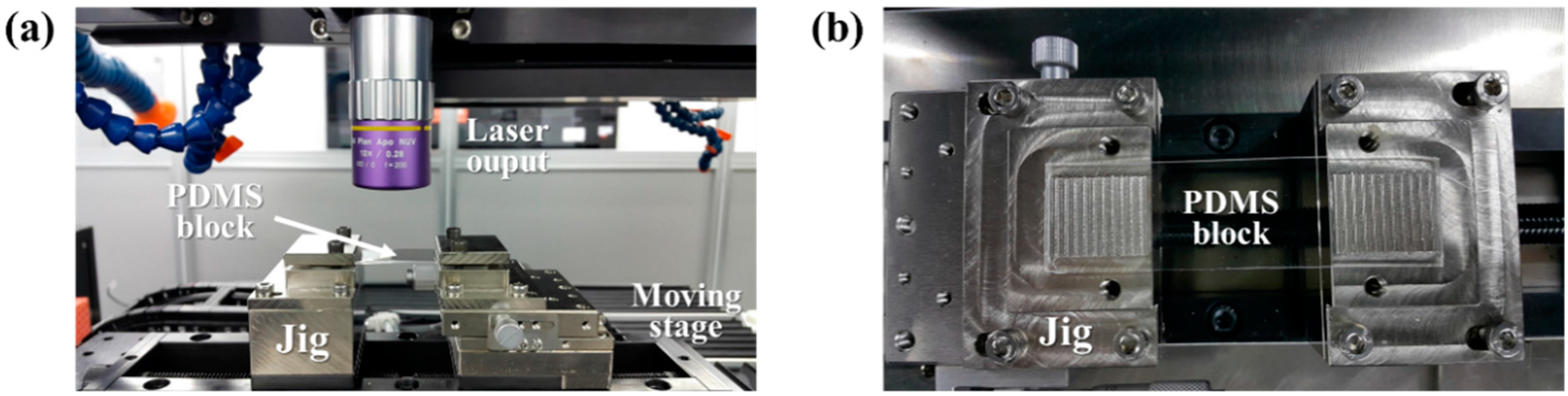
A 5-mm thick PDMS block was placed on the jig for micro-scribing in an unenclosed environment, as shown in Figure 1a. To find the exact location of the top surface, the sample was scanned using the focal distance of the attenuated beam in the z-direction. A two-dimensional channel drawing was loaded into the laser system, and laser micro-scribing was performed. To investigate the geometric characteristics of the micro-channels, the PDMS samples were ablated with various laser intensities according to the energy doses of 1%, 5%, 10%, 15% and 20% of the energy peak (Table 1). For each energy dose, the process was performed with 5, 10 and 15 laser beam passes. After the laser micro-scribing, the samples were cross-sectioned using a razor blade. The cross-sectioned surface was sputter-coated with Pt, and then the geometric features were observed using a field-emission scanning electron microscope (FE-SEM; SUPRA 40VP, Carl Zeiss AG, Oberkochen, Germany). The experiments were repeated three times to confirm reproducibility.
2.3. DNA Preparation
A volume of 100 μL of lambda DNA (concentration of 0.3 μg/μL) (SD0011, Thermo Scientific, Waltham, MA, USA) was stained with 7.5 μL of YOYO-1 dye (Y3601, Invitrogen, Carlsbad, CA, USA) and placed in an oven at 55 °C for 2 h. To remove the remaining dye, 100 μL of Tris-Borate-EDTA buffer (TBE) solution (T7527, Sigma-Aldrich, St. Louis, MO, USA) was added to the incubated solution, and then the stained lambda DNA solution was centrifuged with a centrifugal force (RCF) of 12,000 g for 2 min. The washing process was repeated three times. The washed DNA solution was filtered through a 0.2-μm syringe filter. Finally, the filtered DNA solution was diluted to 1:100 in TBE buffer.
2.4. Computer-Aided Simulation for Microfluidic Channel Optimization
A three-dimensional microfluidic simulation model was prepared to conduct the design optimization of the DNA distributor using Comsol Multiphysics Software (COMSOL, Inc., Burlington, MA, USA). Based on the geometrical characterization results of the laser-ablated micro-channels, the computer-aided simulation was performed on the triangular sections scribed at an energy dose of 5% with 5 laser beam passes. The geometry of the DNA distributor consisted of one inlet and one outlet. For the computational analysis, the incompressible Navier–Stokes equation was applied as follows.
The parameters and u are the density and velocity vector, respectively. The parameter F is the volume force vector, and p is the pressure. The dynamic viscosity, μ, was constant at 0.001 Pa s. The flow was laminar with no slip conditions on the wall. The computer-aided simulation was conducted with inlet flow rates of 1, 5 and 15 /min. To obtain smooth results, second-order Lagrangian mesh elements were applied, and a mesh optimization was conducted until the results converged to less than 0.1% error. After the numerical analysis was completed, the cross-section of the micro-channel was cut and the velocity distribution on the 2D surface was analyzed. In addition, the average velocity for each channel section was calculated at different flow rates.
2.5. Microfluidic Experiment
To prepare the microfluidic experiments, the PDMS block with the fabricated micro-channels from a femtosecond laser was cut to 25 mm × 25 mm. A 1-mm hole was created in the PDMS substrate with micro-channels to prepare the inlet and outlet for the DNA-based microfluidic experiments. To bond the prepared PDMS substrate to a glass slide (25 mm × 75 mm), the PDMS substrate was exposed to plasma discharge (Cute MP; FEMTO science, Yongin, Korea) at a power of 70 W for 40 s. The pressure of the plasma process was maintained at 0.5 torr. The inlet of the microfluidic system was connected to a syringe pump (Pump 11 Elite; Harvard apparatus, Holliston, MA, USA). The DNA solution was infused into the microfluidic channels at flow rates of 1, 5 and 15 μL/min. The DNA distribution in the micro-channels was observed using a fluorescent microscope. The experiments were conducted three times. The difference in fluorescence intensity for YOYO-1 DNA at each channel location was analyzed using Image J software (NIH, Bethesda, ML, USA) developed at the National Institute of Health (NIH).
3. Results and Discussions
3.1. Analysis of Cross-Sectional Images of the Micro-channel
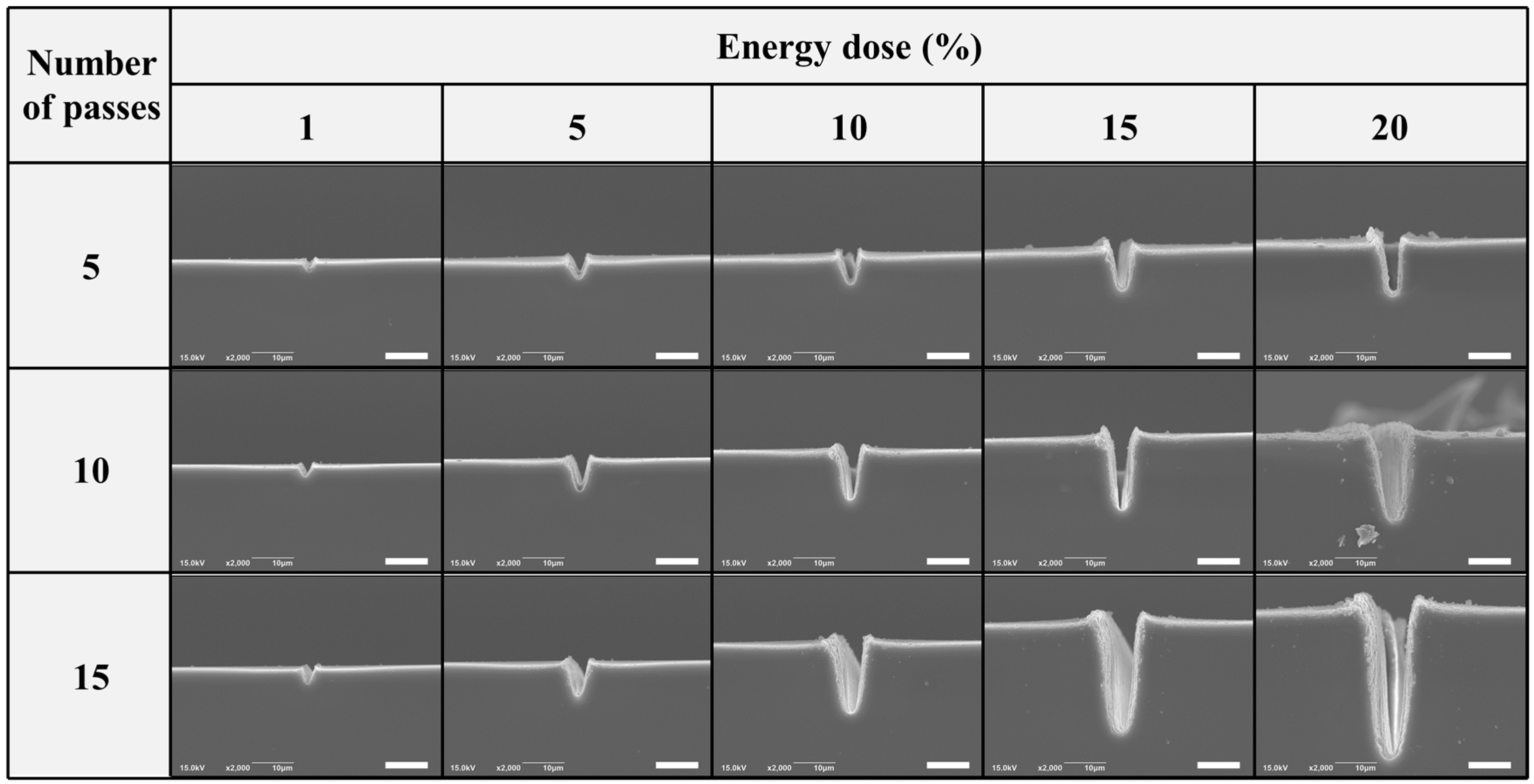
Figure 2 shows the cross-sectional images of the femtosecond laser micro-scribed micro-channels. As the energy doses increased, the width and depth of the micro-channels increased. Specifically, for a larger energy dose, a larger bulging area was observed near the micro-scribed surface due to thermal damage. In addition, the shape of the bottom changed from a sharp to blunt edge as the thermal energy from the laser beam accumulated. The number of laser beam passes was one of the major parameters that affected the micro-channel geometry. When the laser beam passes were repeated, the width and depth were wider and deeper, respectively. As the laser beam pass increased, the equilateral triangle was stretched in the depth direction to form an isosceles triangle. Similar to the energy dose, the sharpness of the bottom area was gradually changed from a sharp to a blunt edge. The repeated laser beam passes caused a larger bulging area because of thermal damage.
Increasing the energy dose and number of laser beam passes had a synergic effect on the generation of the micro-channel. A deeper ablation was observed when the energy dose was 15 laser beam passes than at 5 laser beam passes. This could occur because the accumulated energy from the repeated laser beam passes did not have time to dissipate to the surroundings, thus increasing the thermal damage.
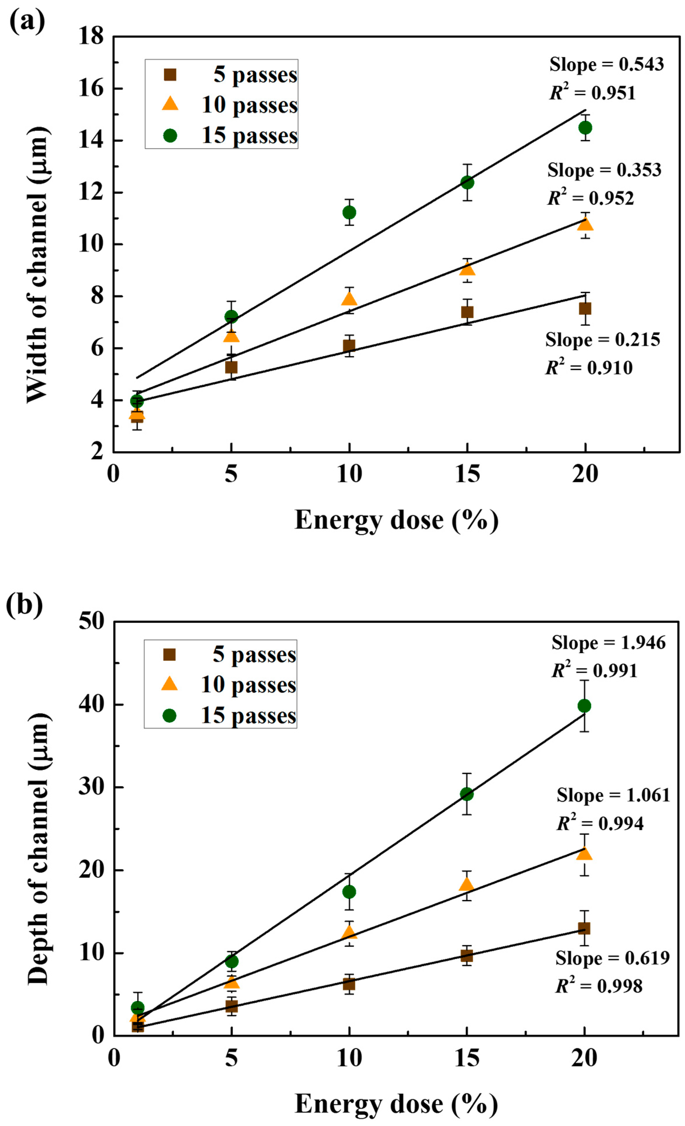
Figure 3a,b show the measured depth and width of the micro-channels using SEM images, respectively. Overall, the depth and width of the micro-channels were proportional to the energy dose and number of laser beam passes. In Figure 3a, the depth at five laser beam passes linearly increased from 1.20 ± 0.40 to 12.99 ± 2.12 μm when the energy dose changed from 1 to 20%. The slope, the ratio of the channel depth to the energy dose, at five laser beam passes was 0.619 (R2 = 0.998). The slopes at 10 and 15 laser beam passes were 1.7 and 3 times greater the slope at five laser beam passes, respectively. Even though the energy dose increased equally, a nonlinear accumulation of total thermal energy could occur as the laser beam passes were repeated.
In Figure 3b, the width at 5 laser beam passes linearly increased from 3.36 ± 0.51 to 7.52 ± 0.63 μm when the energy dose increased from 1 to 20%. The slope, the ratio of the channel width to the energy dose, at 5 laser beam passes was 0.215 (R2 = 0.910). The change in the channel width was smaller than that of the depth of the micro-channels due to the Gaussian distribution and straight laser beam. The slopes at 10 and 15 laser beam passes were 1.6 and 2.5 times greater than the slope at 5 laser beam passes, respectively, due to the analysis previously discussed for Figure 3a.
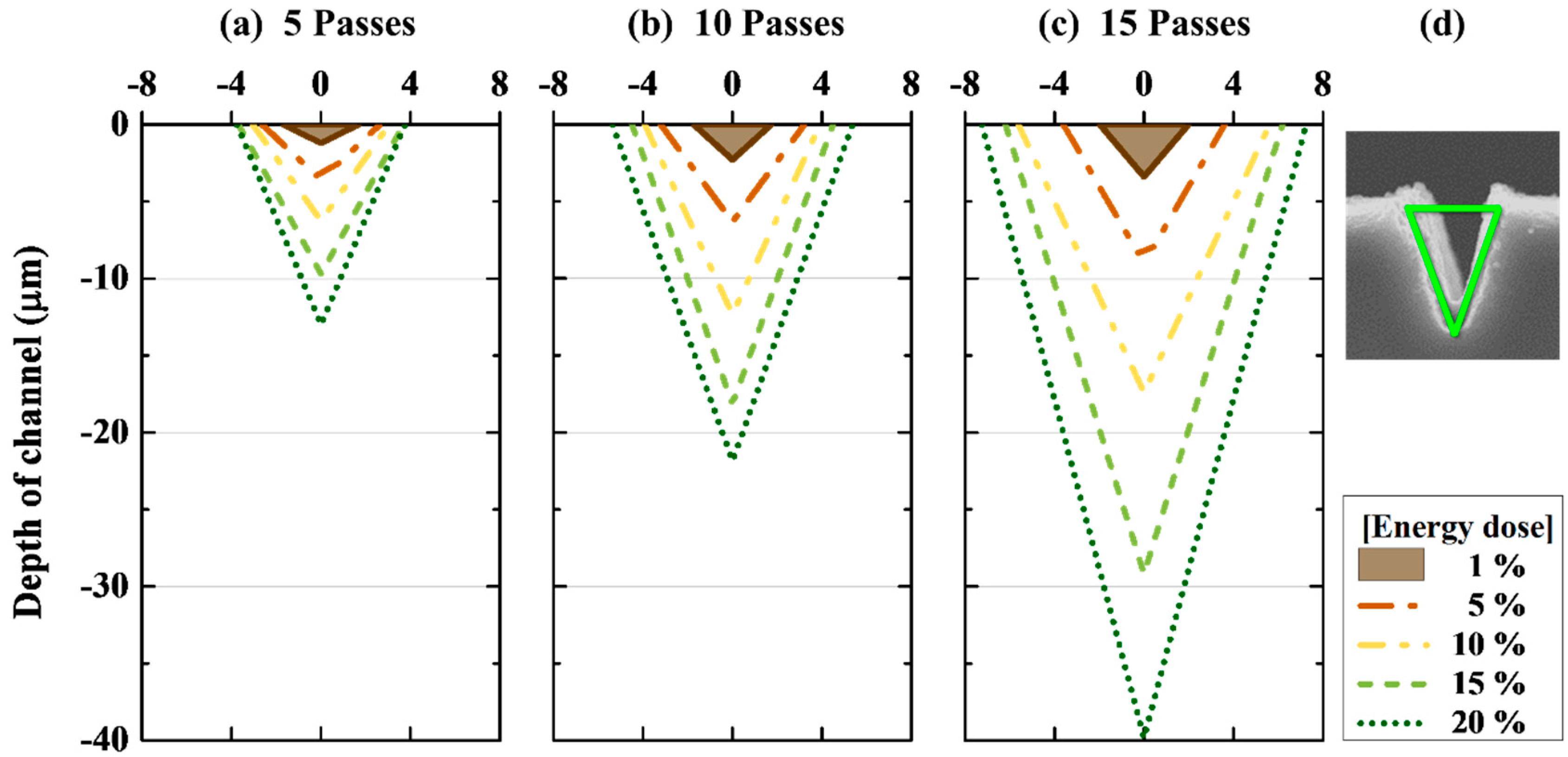
Figure 4 shows the cross-section of the micro-channel that was normalized to a triangle at 5, 10 and 15 laser beam passes. When comparing the shape of the triangles, the aspect ratios of the depth to width were proportionally increased with an increase in the laser beam passes.
In Figure 4a at a laser beam passes of 5, the aspect ratio changed from 0.71 ± 0.13 to 3.45 ± 0.28 when the energy dose was increased from 1 to 20%. Therefore, the larger energy dose generated a higher aspect ratio. In Figure 4b,c, as the laser beam passes increased to 15 passes, the aspect ratios were increased from 1.33 ± 0.29 to 4.07 ± 0.27 and 1.71 ± 0.79 to 5.50 ± 0.24 at 10 and 15 laser beam passes, respectively. The depth and width of the laser micro-scribed channels were 3 times greater with an increase of the laser beam passes; however, the aspect ratio was approximately 1.6 times greater.
3.2. Computational Analysis of a DNA Distributor
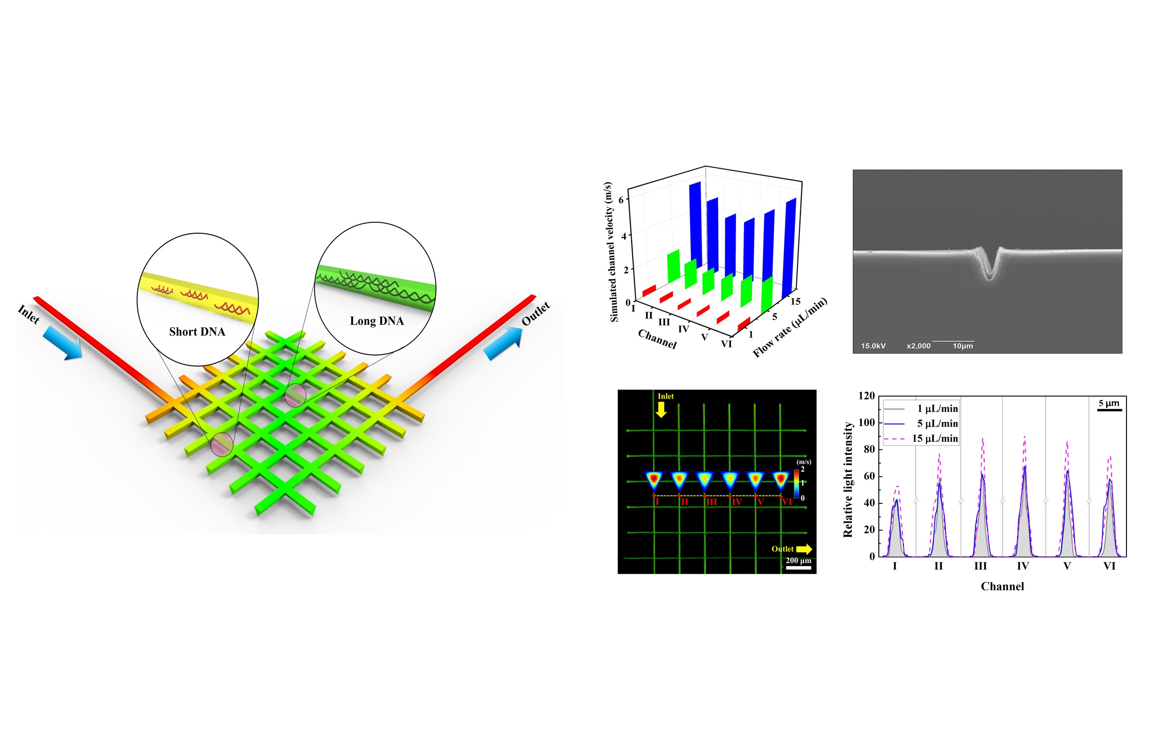
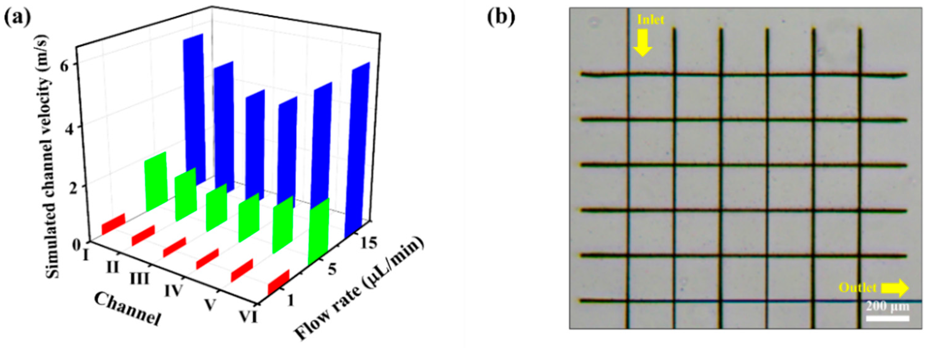
Figure 5a shows the simulated cross-sectional velocity profiles in the 3D modeled micro-channels at DNA solution flow rates of 1, 5 and 15 μL/min. At a flow rate of 1 μL/min, no significant difference in velocity was observed between the channels. As the flow rate of the DNA solution was increased, the velocity demonstrated a larger increase in the outer channel than in the middle channel. This trend became more pronounced when the flow rate increased to 15 μL/min. The peak average velocity in the outer channel was 5.72 m/s, while the minimum average velocity estimated in the middle channel was 4.05 m/s.
3.3. Microfluidic Distribution of the DNA
Figure 5b shows a microscopic image of the fabricated DNA distributor using femtosecond laser ablation (energy dose of 5% at a laser beam pass of 5) based on the computer simulation results. The channel width observed from the top view was uniform, and the bulging phenomenon was minimal around the channel profile. However, at the beginning and end of laser processing, the micro-channels were slightly larger as the laser beam remained longer at the tip. Thus, the channels were further extended over the intersection to prevent laser-machining errors at the beginning and end of laser processing. During fabrication, we found that the dimensions of the crossings between two perpendicular channels became about 1.5 times larger due to double irradiation of the laser beam. However, the double laser-irradiated region was very small compared to the grid spacing (200 μm). Thus, we assumed that the size effect of the double-irradiated crossings on microfluidic flow was negligible.
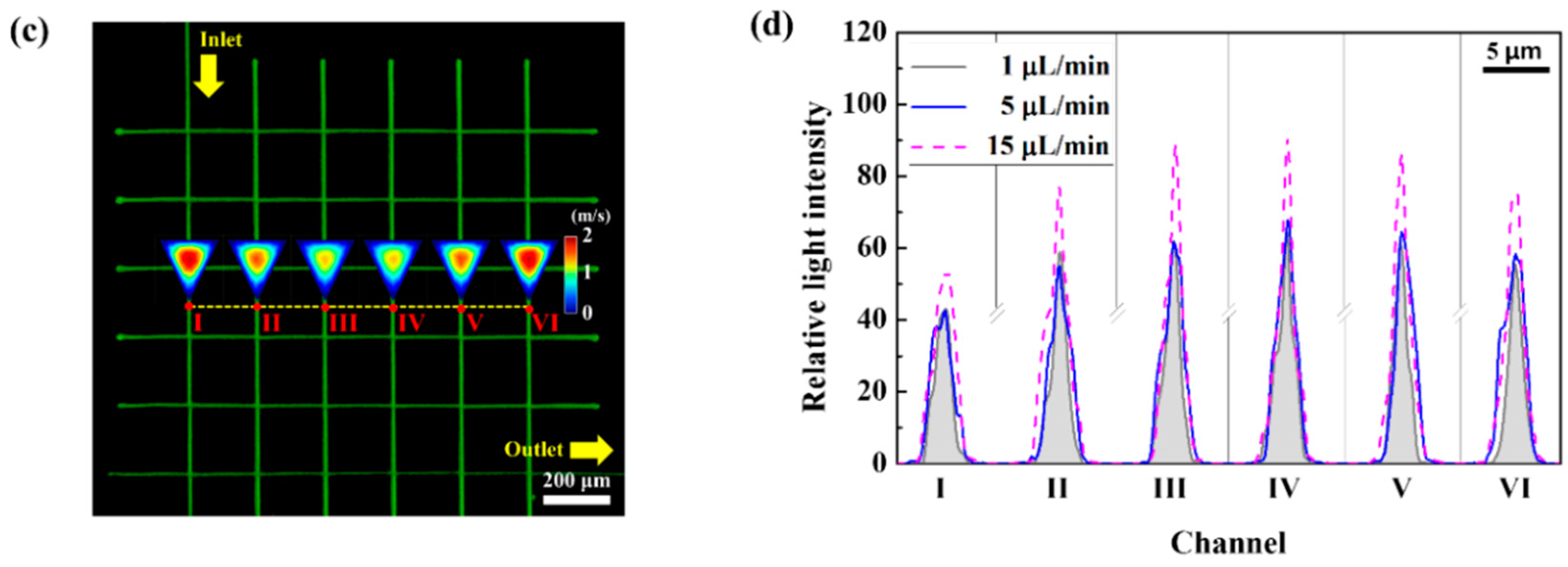
Figure 5c,d represent a fluorescent image and relative light intensity graph of the YOYO-1 DNA solution distributed using the microfluidics at a flow rate of 5 μL/min. For the microfluidics, the fluorescent intensities varied with the location due to various velocity gradients as the DNA solution passed through the micro-channels. When the fluorescence intensity was the lowest (Figure 5d), the fastest velocity profile was shown in the computational simulation (Figure 5c). Our assumption was that the longer DNA would show the higher fluorescent intensity based on the previously reported reference [30]. For a brighter fluorescent intensity, longer DNA would be distributed at a low flow velocity. The fluorescent intensity was analyzed using a line profile, as shown in Figure 5d. At the highest flow rate of 15 μL/min, the relative light intensity was the strongest at the middle channels (90.84 ± 15.56 at point IV) and the lowest at the outer channel (53.87 ± 5.69 at point I). In this study, we tried to show the feasibility of DNA distributor fabricated by femtosecond laser micro-scribing, which can lead to a novel technique to easily and simply determine how various lengths of DNA are mixed in a solution.
4. Conclusions
To confirm the polymer processability of the femtosecond laser, microfluidic channels of 10 μm or less were fabricated. The shape of the femtosecond laser-processed micro-channels was characterized by the energy dose and the number of laser beam passes. The depth and width of the micro-channels showed a linear proportion as a function of the energy dose and the number of laser beam passes. The DNA distributor was fabricated with an energy dose of 5% at a laser beam pass of 5 based on the optimized design using the computational simulation. In the simulation, a higher velocity in the outer channel than in the middle channel was estimated. From the DNA distribution experiment, a brighter fluorescent intensity for YOYO-1 DNA was observed at the middle channels, where the lowest velocity profile was expected in the computational simulation. Therefore, longer DNA can flow at a low velocity creating a brighter fluorescent intensity. Conversely, shorter DNA can be distributed in the outer channel, where the velocity was fast.
The fabricated DNA distributor was successfully applied to experimentally determine the distribution of DNA with various lengths. Ultrafast laser micro-scribing is a versatile processing technique for the maskless fabrication of various sub 10-μm microfluidic channels in polymer-based bio-applications.
Acknowledgments
This work was supported by a National Research Foundation of Korea (NRF) grant funded by the Korean government (MSIP) (NRF-2017R1A4A1015681).
Author Contributions
Jinmu Jung and Jonghyun Oh conceived and designed the experiments; Hojun Shin and Hyojae Kim performed the experiments and wrote the paper; Yeongseok Jang analyzed the data; Jinmu Jung and Jonghyun Oh revised the paper.
Conflicts of Interest
The authors declare no conflict of interest.
References
- Von der Linde, D.; Sokolowski-Tinten, K. The physical mechanisms of short-pulse laser ablation. Appl. Surf. Sci. 2000, 154, 1–10. [Google Scholar] [CrossRef]
- Hsieh, Y.K.; Chen, S.C.; Huang, W.L.; Hsu, K.P.; Gorday, K.A.V.; Wang, T.; Wang, J. Direct Micromachining of Microfluidic Channels on Biodegradable Materials Using Laser Ablation. Poymers 2017, 9, 242. [Google Scholar] [CrossRef]
- Sun, Y.L.; Dong, W.F.; Niu, L.G.; Jiang, T.; Liu, D.X.; Zhang, L.; Wang, Y.S.; Kim, D.P.; Sun, H.B. Protein-based soft micro-optics fabricated by femtosecond laser direct writing. Light Sci. Appl. 2014, 3, e129. [Google Scholar] [CrossRef]
- Malek, C.G.K. Laser processing for bio-microfluidics applications (part I). Anal. Bioanal. Chem. 2006, 385, 1351–1361. [Google Scholar] [CrossRef] [PubMed]
- Malek, C.G.K. Laser processing for bio-microfluidics applications (part II). Anal. Bioanal. Chem. 2006, 385, 1362–1369. [Google Scholar] [CrossRef] [PubMed]
- Xu, J.; Kawano, H.; Liu, W.; Hanada, Y.; Lu, P.; Miyawaki, A.; Midorikawa, K.; Sugioka, K. Controllable alignment of elongated microorganisms in 3D microspace using electrofluidic devices manufactured by hybrid femtosecond laser microfabrication. Microsyst. Nanoeng. 2017, 3, 16078. [Google Scholar] [CrossRef]
- Tavangar, A.; Tan, B.; Venkatakrishnan, K. Synthesis of bio-functionalized three-dimensional titania nanofibrous structures using femtosecond laser ablation. Acta Biomater. 2011, 7, 2726–2732. [Google Scholar] [CrossRef] [PubMed]
- Oraevsky, A.A.; Silva, L.B.D.; Rubenchik, A.M.; Feit, M.D.; Glinsky, M.E.; Perry, M.D.; Mammini, B.M.; Small, W.; Stuart, B.C. Plasma mediated ablation of biological tissues with nanosecond-to-femtosecond laser pulses: Relative role of linear and nonlinear absorption. IEEE J. Sel. Top. Quant. 1996, 2, 801–809. [Google Scholar] [CrossRef]
- Shah, R.; Shah, S.; Sengupta, S. Results of small incision lenticule extraction: All-in-one femtosecond laser refractive surgery. J. Cataract Refract. Surg. 2011, 37, 127–137. [Google Scholar] [CrossRef] [PubMed]
- Serbin, J.; Bauer, T.; Fallnich, C.; Kasenbacher, A.; Arnold, W.H. Femtosecond lasers as novel tool in dental surgery. Appl. Surf. Sci. 2002, 197, 737–740. [Google Scholar] [CrossRef]
- Gomez, C.; Costela, A.; García-Moreno, I.; Llanes, F.; Teijón, J.M.; Blanco, D. Laser treatments on skin enhancing and controlling transdermal delivery of 5-fluorouracil. Lasers Surg. Med. 2008, 40, 6–12. [Google Scholar] [CrossRef] [PubMed]
- Novoselov, K.S.; Fal, V.; Colombo, L.; Gellert, P.; Schwab, M.; Kim, K. A roadmap for graphene. Nature 2012, 490, 192–200. [Google Scholar] [CrossRef] [PubMed]
- Qian, W.; Murakami, M.; Ichikawa, Y.; Che, Y. Highly efficient and controllable PEGylation of gold nanoparticles prepared by femtosecond laser ablation in water. J. Phys. Chem. C 2011, 115, 23293–23298. [Google Scholar] [CrossRef]
- Knowles, M.; Rutterford, G.; Karnakis, D.; Ferguson, A. Micro-machining of metals, ceramics and polymers using nanosecond lasers. Int. J. Adv. Manuf. Technol. 2007, 33, 95–102. [Google Scholar] [CrossRef]
- Barberoglou, M.; Zorba, V.; Stratakis, E.; Spanakis, E.; Tzanetakis, P.; Anastasiadis, S.; Fotakis, C. Bio-inspired water repellent surfaces produced by ultrafast laser structuring of silicon. Appl. Surf. Sci. 2009, 255, 5425–5429. [Google Scholar] [CrossRef]
- Koch, J.; Fadeeva, E.; Engelbrecht, M.; Ruffert, C.; Gatzen, H.; Ostendorf, A.; Chichkov, B. Maskless nonlinear lithography with femtosecond laser pulses. Appl. Phys. A Mater. 2006, 82, 23–26. [Google Scholar] [CrossRef]
- Sugioka, K.; Cheng, Y. Ultrafast lasers—Reliable tools for advanced materials processing. Light Sci. Appl. 2014, 3, e149. [Google Scholar] [CrossRef]
- Vorobyev, A.Y.; Guo, C. Direct femtosecond laser surface nano/microstructuring and its applications. Laser Photonics Rev. 2013, 7, 385–407. [Google Scholar] [CrossRef]
- Wolfe, D.B.; Ashcom, J.B.; Hwang, J.C.; Schaffer, C.B.; Mazur, E.; Whitesides, G.M. Customization of Poly (dimethylsiloxane) Stamps by Micromachining Using a Femtosecond-Pulsed Laser. Adv. Mater. 2003, 15, 62–65. [Google Scholar] [CrossRef]
- Darvishi, S.; Cubaud, T.; Longtin, J.P. Ultrafast laser machining of tapered microchannels in glass and PDMS. Opt. Lasers Eng. 2012, 50, 210–214. [Google Scholar] [CrossRef]
- Yong, J.; Chen, F.; Yang, Q.; Du, G.; Bian, H.; Zhang, D.; Si, J.; Yun, F.; Hou, X. Rapid fabrication of large-area concave microlens arrays on PDMS by a femtosecond laser. ACS Appl. Mater. Interfaces 2013, 5, 9382–9385. [Google Scholar] [CrossRef] [PubMed]
- Lu, D.-X.; Zhang, Y.-L.; Han, D.-D.; Wang, H.; Xia, H.; Chen, Q.-D.; Ding, H.; Sun, H.-B. Solvent-tunable PDMS microlens fabricated by femtosecond laser direct writing. J. Mater. Chem. C 2015, 3, 1751–1756. [Google Scholar] [CrossRef]
- Stankova, N.; Atanasov, P.; Nikov, R.G.; Nikov, R.; Nedyalkov, N.; Stoyanchov, T.; Fukata, N.; Kolev, K.; Valova, E.; Georgieva, J. Optical properties of polydimethylsiloxane (PDMS) during nanosecond laser processing. Appl. Surf. Sci. 2016, 374, 96–103. [Google Scholar] [CrossRef]
- Surdo, S.; Piazza, S.; Ceseracciu, L.; Diaspro, A.; Duocastella, M. Towards nanopatterning by femtosecond laser ablation of pre-stretched elastomers. Appl. Surf. Sci. 2016, 374, 151–156. [Google Scholar] [CrossRef]
- Farshchian, B.; Gatabi, J.R.; Bernick, S.M.; Park, S.; Lee, G.-H.; Droopad, R.; Kim, N. Laser-induced superhydrophobic grid patterns on PDMS for droplet arrays formation. Appl. Surf. Sci. 2017, 396, 359–365. [Google Scholar] [CrossRef]
- Selimović, Š.; Piraino, F.; Bae, H.; Rasponi, M.; Redaelli, A.; Khademhosseini, A. Microfabricated polyester conical microwells for cell culture applications. Lab Chip 2011, 11, 2325–2332. [Google Scholar] [CrossRef] [PubMed] [Green Version]
- Piraino, F.; Selimović, Š.; Adamo, M.; Pero, A.; Manoucheri, S.; Bok Kim, S.; Demarchi, D.; Khademhosseini, A. Polyester μ-assay chip for stem cell studies. Biomicrofluidics 2012, 6, 044109. [Google Scholar] [CrossRef] [PubMed]
- Kim, T.M.; Groisman, A.; Kleinfeld, D.; Schaffer, C.B. Customization of microfluidic devices using femtosecond laser micromachining. In Ultrashort Laser Microprocessing of Materials III, Proceedings of Frontiers in Optics 2003, Tucson, AZ, USA, 5 October 2003; Optical Society of America: Washington, DC, USA, 2003. [Google Scholar]
- Lopa, S.; Piraino, F.; Kemp, R.J.; Di Caro, C.; Lovati, A.B.; Di Giancamillo, A.; Moroni, L.; Peretti, G.M.; Rasponi, M.; Moretti, M. Fabrication of multi-well chips for spheroid cultures and implantable constructs through rapid prototyping techniques. Biotechnol. Bioeng. 2015, 112, 1457–1471. [Google Scholar] [CrossRef] [PubMed] [Green Version]
- Laib, S.; Rankl, M.; Ruckstuhl, T.; Seeger, S. Sizing of single fluorescently stained DNA fragments by scanning microscopy. Nucleic Acids Res. 2003, 31, e138. [Google Scholar] [CrossRef] [PubMed]
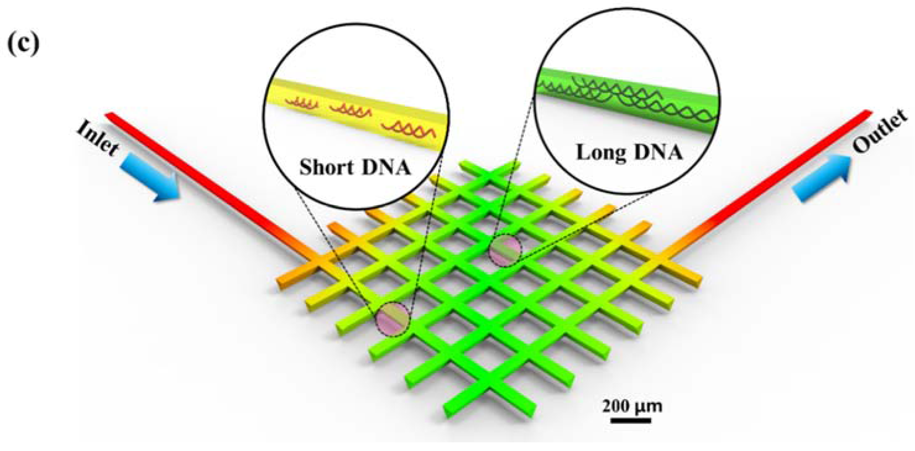
Figure 1.
Schematics of the femtosecond laser micro-scribing system and a microfluidic DNA distributor. Image (a) shows an overall view of the femtosecond laser system; Image (b) shows the jig used for polymer sample fixation; and (c) shows a schematic of the microfluidic DNA distributor (channel spacing 200 μm × 200 μm).


Figure 2.
Cross-sectional SEM images of the femtosecond laser micro-scribed channels according to the energy doses and number of laser beam passes. All scale bars are 10 μm.
Figure 2.
Cross-sectional SEM images of the femtosecond laser micro-scribed channels according to the energy doses and number of laser beam passes. All scale bars are 10 μm.

Figure 3.
Characterization of the (a) depth and (b) width of the femtosecond laser micro-scribed channels.
Figure 3.
Characterization of the (a) depth and (b) width of the femtosecond laser micro-scribed channels.

Figure 4.
Aspect ratio of the cross-section of the laser-scribed micro-channels at (a) 5 passes; (b) 10 passes; and (c) 15 passes, respectively; (d) a cross-sectional SEM image of micro-channel for aspect ratio measurement.
Figure 4.
Aspect ratio of the cross-section of the laser-scribed micro-channels at (a) 5 passes; (b) 10 passes; and (c) 15 passes, respectively; (d) a cross-sectional SEM image of micro-channel for aspect ratio measurement.

Figure 5.
Simulated and experimental results of a microfluidic DNA distributor. Image (a) shows the simulated channel velocity at various flow rates (1, 5 and 15 μL/min); Image (b) shows the DNA distributor fabricated at an energy dose of 5% and a laser beam pass of 5; Image (c) shows a fluorescent image of DNA flowing at various channels with the simulated cross-sectional velocity; and (d) shows the characterization of the relative light intensity for YOYO-1 DNA according to the dotted line profile in (c) with various flow rates in the micro-channels.


Table 1.
Summary of the laser micro-scribing parameter at various laser intensities in terms of energy doses.
Table 1.
Summary of the laser micro-scribing parameter at various laser intensities in terms of energy doses.
| Energy Dose (%) | Pulse Energy (μJ) | Laser Fluence (J/cm2) |
|---|---|---|
| 1 | 3.75 | 19.11 |
| 5 | 18.75 | 95.54 |
| 10 | 37.50 | 191.08 |
| 15 | 56.25 | 286.62 |
| 20 | 75.00 | 382.16 |
© 2017 by the authors. Licensee MDPI, Basel, Switzerland. This article is an open access article distributed under the terms and conditions of the Creative Commons Attribution (CC BY) license (http://creativecommons.org/licenses/by/4.0/).
Share and Cite
MDPI and ACS Style
Shin, H.; Kim, H.; Jang, Y.; Jung, J.; Oh, J. Femtosecond Laser-Inscripted Direct Ultrafast Fabrication of a DNA Distributor Using Microfluidics. Appl. Sci. 2017, 7, 1083. https://doi.org/10.3390/app7101083
AMA Style
Shin H, Kim H, Jang Y, Jung J, Oh J. Femtosecond Laser-Inscripted Direct Ultrafast Fabrication of a DNA Distributor Using Microfluidics. Applied Sciences. 2017; 7(10):1083. https://doi.org/10.3390/app7101083
Chicago/Turabian StyleShin, Hojun, Hyojae Kim, Yeongseok Jang, Jinmu Jung, and Jonghyun Oh. 2017. "Femtosecond Laser-Inscripted Direct Ultrafast Fabrication of a DNA Distributor Using Microfluidics" Applied Sciences 7, no. 10: 1083. https://doi.org/10.3390/app7101083
Note that from the first issue of 2016, this journal uses article numbers instead of page numbers. See further details here.