3D-Printed Super-Wideband Spidron Fractal Cube Antenna with Laminated Copper
by

Oh Heon Kwon
1, 
Won Bin Park
1,
Sungwoo Lee
1,
Jong Min Lee
1,
Young Mi Park
2 and
Keum Cheol Hwang
1,* 1
School of Electronic and Electrical Engineering, Sungkyunkwan University, Suwon 440-746, Korea
2
Electronic Warfare PMO, Agency for Defense Development, Daejeon 305-600, Korea
*
Author to whom correspondence should be addressed.
Appl. Sci. 2017, 7(10), 979; https://doi.org/10.3390/app7100979
Submission received: 3 August 2017
/
Revised: 4 September 2017
/
Accepted: 19 September 2017
/
Published: 22 September 2017
(This article belongs to the Special Issue 3D Printed Antennas)
Abstract
:In this paper, a 3D-printed super-wideband (SWB) Spidron fractal cube antenna is proposed. The Spidron fractal configuration is utilized as a self-complementary structure on each face of a 3D frame to attain SWB characteristics. The antenna is excited through a tapered microstrip balun for both mode transforming and impedance matching. A prototype of the proposed antenna, including the 3D frame fabricated with the help of a 3D printer and Spidron fractal patches made of copper tape, is experimentally verified. The measured −10 dB reflection ratio bandwidth is 34:1 (0.44–15.38 GHz). The peak gain varies from 3.42 to 9.29 dBi within the operating frequency bandwidth. The measured radiation patterns are nearly omnidirectional at all operating frequency bands.
1. Introduction
From the late 1950s to the early 1960s, antennas with a reflection ratio bandwidth of 10:1 or greater (e.g., log-periodic dipole and equiangular spiral types) started to be developed [1]. At that time, these antennas were known as frequency-independent antennas, but they are currently referred to as super-wideband (SWB) antennas. SWB antennas have received much attention in military and civilian systems because their broadband characteristics can provide high data-rate services [2]. For this reason, several 2D and 3D SWB antennas have been introduced [3,4,5,6,7]. The modified star-triangular fractal monopole antenna introduced by Waladi et al. [3] and the asymmetric coplanar strip fed hexagonal loop antenna from Trinh-Van et al. [4] have 2D geometries and compact sizes, meeting the −10 dB reflection ratio bandwidth requirement of 30:1 or greater. However, their performances can deteriorate with changes in the ground size or platform. In other work [5,6,7], 3D SWB antennas with a monopolar patch and dielectric resonator were proposed. It was found that these antennas are insensitive to the ground platform used; however, the fabrication of the 3D structure of these antennas remains a challenge. Moreover, their weight is increased due to the use of a dielectric resonator.
A self-complementary structure in which the geometries of the conductor and non-conductor parts are nearly identical was proposed by Yasuto Mushiake in 1948 to realize frequency-independent properties [8]. Owing to this feature, wide bandwidth characteristics are easily achieved. Accordingly, various wideband self-complementary antennas have been published [9,10]. Chun-Cheng suggested a bow-tie-shaped quasi-self-complementary antenna [9]. In another study [10], an arrow-shaped self-complementary antenna for WLAN/WiMAX applications was proposed. These antennas are small and have wide bandwidths but do not have SWB characteristics. On the other hand, antennas that demonstrate SWB characteristics using a self-complementary structure have also been proposed [11,12]. Cortes-Medellin proposed a non-planar log-periodic antenna with a quasi-self-complementary structure and analyzed the performance and characteristics of the antenna in detail [11]. However, the antenna was still heavy due to the thick metal used to make it. In another study [12], a spherical self-complementary antenna was introduced. This antenna was designed with a teardrop-shaped loop to maintain a self-complementary structure and was fabricated using a 3D printer. Although the antenna is light due to the 3D printing procedure, its measured result does not meet the 10:1 reflection ratio bandwidth requirement.
Previously, we introduced two-dimensional Spidron fractal configurations for various antenna applications—specifically, a Spidron fractal slot antenna with a grooved dielectric resonator [13] and a uniplanar electromagnetic bandgap employing a modified Spidron fractal geometry [14]. In the present paper, a novel 3D-printed SWB cube antenna with a Spidron fractal configuration is proposed. Each parameter of the Spidron fractal geometry is set to satisfy the requirement of the self-complementary condition, and the antenna is fed by a tapered microstrip balun [15]. As a result, the proposed antenna achieves SWB characteristics. ANSYS high-frequency structure simulator (HFSS) software is used to conduct all simulations in this paper. In addition, 3D printing technology is applied for the simple fabrication of a prototype of the antenna. The proposed antenna with its tapered balun is measured to verify simulated results. The designs of the antenna and the balun are introduced in Section 2. Section 3 presents a comparison between the measured and simulated results. Finally, the conclusion is given in Section 4.
2. Antenna Design
Figure 1a shows the concept of the Spidron fractal, depicting a planar figure that includes a series of contiguous right triangles which are scaled down and added to the hypotenuse of a larger triangle [16]. Each triangle has the identical angular factor of , with the down-scaling factor defined as follows:
Figure 1b illustrates the self-complementary geometry realized by combining Spidron fractal structures. To meet the self-complementary requirements, the side length of the largest triangle of the Spidron fractal is set to S/2, where the side length of the face is denoted as S and the common angular factor is 45.
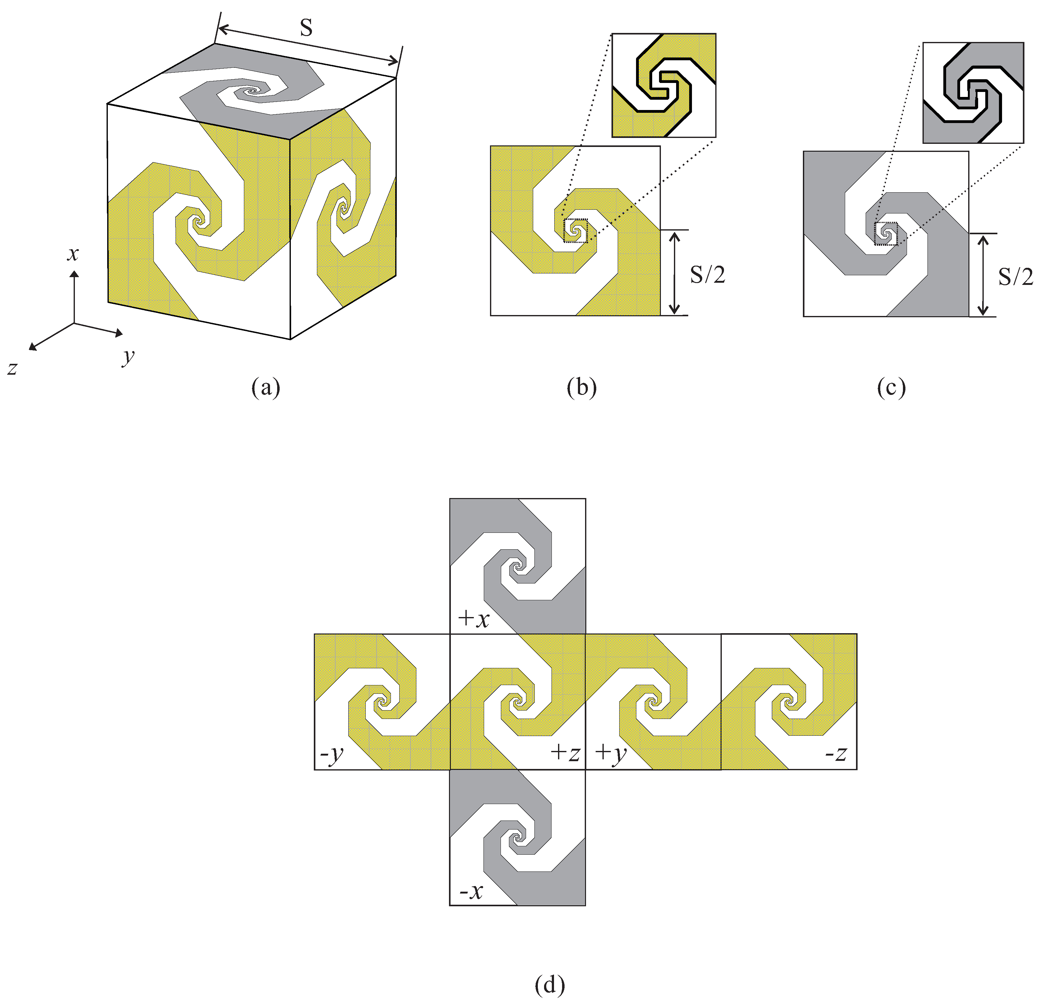
The geometry of the proposed 3D-printed SWB Spidron fractal antenna with coordinate systems is illustrated in Figure 2. Each face of the proposed antenna consists of a Spidron fractal structure which is composed of ten isosceles right triangles. Each edge has a length S of 170 mm considering the lowest operating frequency. A 3D view of the antenna is given in Figure 2a. As shown in this figure, two Spidron fractal patches on each of four faces along the x- and z-directions—referred to as open-state faces—are separated by a small gap (see Figure 2b). Meanwhile, the other two sides along the y-direction—referred to as short-state faces—are where the Spidron fractal patches are connected to each other through a narrow strip (see Figure 2c). Figure 2d shows an expanded planar view of the proposed antenna. Each Spidron fractal patch is attached onto the 3D frame. The frame is made of the 3D printer filament material of acrylonitrile butadiene styrene, which has a dielectric constant of 3.2 and a loss tangent of 0.02. Copper tape is used to realize the Spidron fractal patches.
Figure 3 shows the simulated input impedance of the proposed antenna as fed by a lumped port. As can be observed, the real part () and imaginary part () of the input impedance are around 145- and 0-, respectively. Hence, it is necessary to design a balun to match the impedance of the SMA connector (with the characteristic impedance of 50-) and the input impedance of the antenna. Moreover, the unbalanced mode is excited from the SMA connector, but a balanced mode is needed because the proposed antenna operates as a dipole antenna. Therefore, the balun is required not only for impedance matching but also for mode transforming.
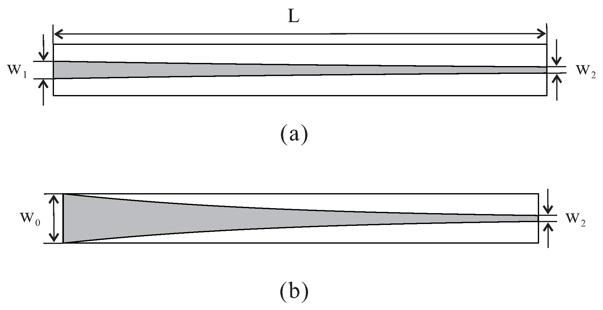
Figure 4a,b show the top and bottom sides of the proposed balun, respectively. According to the exponential function, the widths of the ends of the balun (, and ) are optimized smoothly to transform the impedance from 145- to 50- in broadband. The exponential function can be expressed as [13]:
where a and b are constants determined by the size of the balun. The constants a and b are calculated by , and , respectively. The strip lines on the top and bottom sides of the balun change the mode of excitation from the unbalanced to the balanced mode. In addition, the length L of the balun is determined according to the lowest operating frequency. The derived optimum parameters are as follows: = 10 mm, = 3.4 mm, = 1 mm and L = 150 mm. The proposed balun is printed onto a 1.52-mm-thick RF-35 substrate with a dielectric constant of 3.5 and a loss tangent of 0.0018. The balun is attached perpendicularly to the open-state face at the +z–direction in Figure 2d.
3. Experimental Results and Discussion
Based on design parameters in the pervious section, a prototype of the proposed antenna and balun were fabricated. The 3D frame of the proposed antenna was fabricated using a 3D printer (Cubicon Single Plus, Hyvision system) with acrylonitrile butadiene styrene. The thickness of the 3D frame was set to 2.5 mm in consideration of both the time required for printing as well as durability. The Spidron fractal patches—consisting of copper tape—were directly pasted onto the 3D frame and connected by soldering. To support the 3D frame, styrofoam was attached to the inner side of the Spidron fractal face. The interior of the Spidron fractal cube was empty except for the portion where the Styrofoam was located. Photographs of the fabricated balun and antenna are presented in Figure 5 and Figure 6, respectively.
An Agilent 8510C network analyzer was used to measure the reflection coefficients of the fabricated balun and antenna. Figure 7 depicts the simulated and measured reflection coefficients of the proposed balun. The reflection coefficient was measured by loading a 145- chip resistor at one side of the edge and an SMA connector at the opposite edge. As a result, it could be confirmed that the balun has wideband characteristics. The simulated and measured results of the reflection coefficients of the proposed antenna are illustrated in Figure 8. It was found that the simulated and measured −10 dB reflection ratio bandwidths are 36.7:1 (0.46–16.61 GHz) and 34.9:1 (0.44–15.38 GHz), respectively. These results show that the −10 dB reflection ratio bandwidth meets the SWB requirements.
To measure the radiation patterns and peak gain of the proposed antenna, a dual-polarized rectangular horn antenna in an RF anechoic chamber was utilized. The measured peak gain is illustrated in Figure 9. Note that the peak gain shown in the figure was extracted from the measured three-dimensional radiation pattern. At the operating frequency, the peak gain varies from 3.42 to 9.29 dBi.
Figure 10 plots the measured radiation patterns of two cutting planes (– and –planes) at 0.5 GHz, 8 GHz and 15 GHz. The antenna has nearly omnidirectional radiation patterns at every operating frequency.
All radiation patterns in Figure 10 were obtained from the power sum of the and patterns. As shown in Figure 9 and Figure 10, the peak gain and radiation pattern of the proposed antenna exhibit spiky responses with an increase in the frequency. This is due to the effects of higher order currents when the frequency is increased.
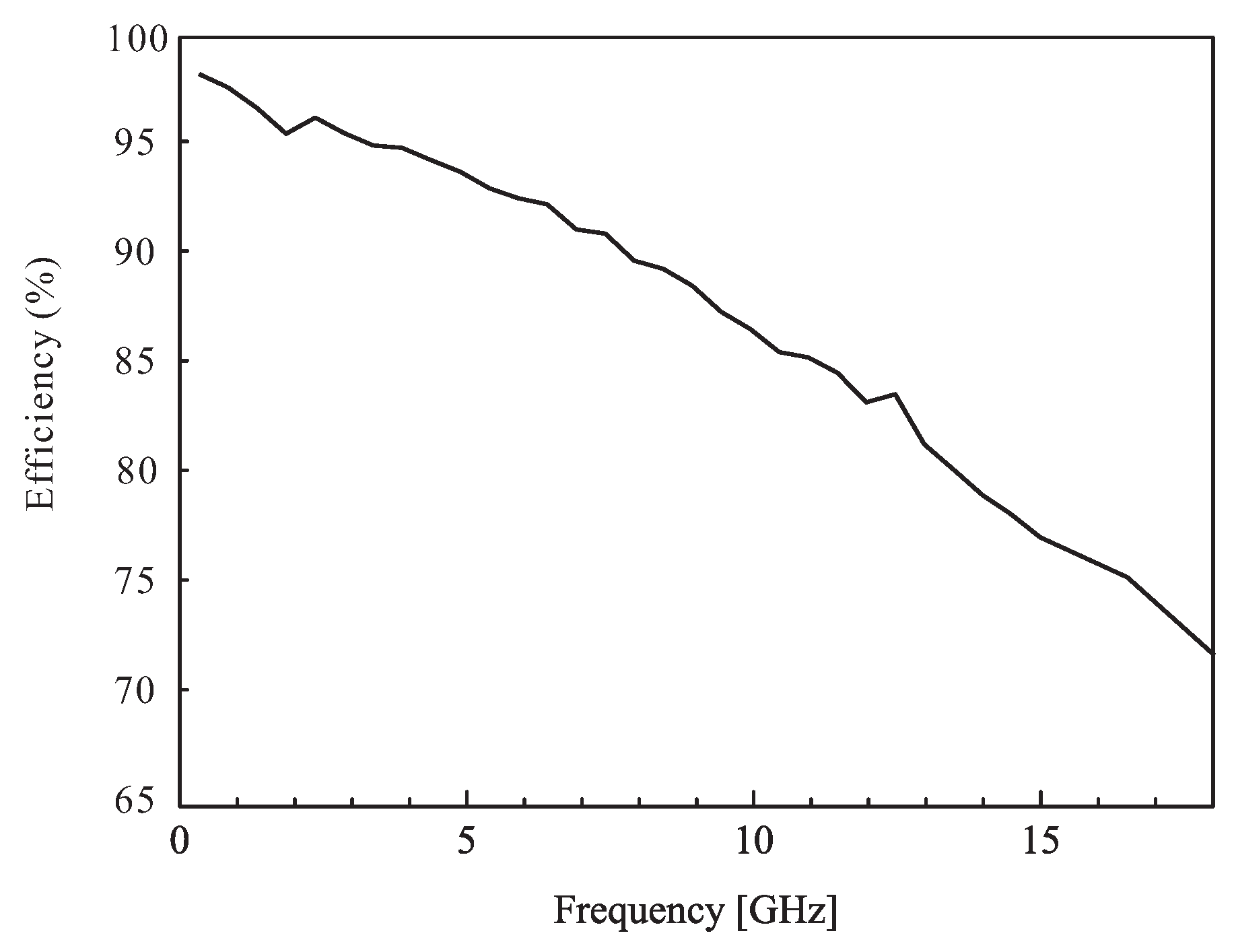
Figure 11 shows the simulated radiation efficiency of the proposed antenna. The radiation efficiency varies from 77% to 98%. As the frequency increases, the loss tangent of the 3D printer filament material increases, so the antenna efficiency decreases with increasing frequency.
To verify the performance, the proposed antenna was compared with previously proposed antennas [5,6,7,9,10,12]. Their bandwidths and sizes are illustrated in Table 1. It is evident that the proposed antenna exhibits a wider operating bandwidth ratio and a smaller size compared to those of previous antennas [5,6,12]. The other antennas [7,9,10] are smaller than the proposed antenna as well. However, the −10 dB reflection ratio bandwidths in the aforementioned studies [7,9,10] are narrower than that of the proposed antenna. From this comparison, it can be seen that the proposed antenna exhibits good performance capabilities in terms of the −10 dB reflection ratio bandwidth and given its small size.
4. Conclusions
A 3D-printed SWB Spidron fractal cube antenna is designed using 3D printing technology. To ensure the SWB characteristics, a self-complementary structure constructed using a Spidron fractal configuration is implemented on each face of a 3D frame, with the conductor part created using copper tape. The proposed antenna is excited by a tapered microstrip balun. The measured −10 dB reflection ratio bandwidth is 34.9:1 (0.44–15.38 GHz). The measured peak gain ranges from 3.42 to 9.29 dBi within the operating frequency band. In addition, the radiation patterns are nearly omnidirectional at every operating frequency. Therefore, the proposed antenna can be feasibly applied in areas which require SWB characteristics.
Acknowledgments
This work was supported by the research fund of Signal Intelligence Research Center supervised by Defense Acquisition Program Administration and Agency for Defense Development of Korea.
Author Contributions
The presented work was carried out in collaboration of all authors. Oh Heon Kwon performed the simulations. Won Bin Park, Sungwoo Lee, Jong Min Lee, Young Mi Park, and Keum Cheol Hwang participated to the conception, fabrication and experiment. Oh Heon Kwon wrote the paper which was edited by all co-authors.
Conflicts of Interest
The authors declare no conflict of interest.
References
- Zhong, S.; Liu, J.-J.; Du, C.-Z.; Xue, L.-L. SWB planar antenna technology. In Proceedings of the China-Japan Joint Microwave Conference, Shanghai, China, 10–12 September 2008; pp. 139–143. [Google Scholar]
- Cao, P.; Haung, Y.; Zhang, J.; Alrawashdeh, R. A compact super wideband monopole antenna. In Proceedings of the 2013 7th European Conference on Antennas and Propagation (EuCAP), Gothenburg, Sweden, 8–12 April 2013; pp. 3107–3110. [Google Scholar]
- Waladi, V.; Mohammadi, N.; Zehforoosh, Y.; Habashi, A.; Nourinia, J. A novel modified star-traingular fractal (MSTF) monopole antenna for super-wideband applications. IEEE Antennas Wirel. Propag. Lett. 2013, 12, 651–654. [Google Scholar] [CrossRef]
- Trinh-Van, S.; Kwon, G.; Hwang, K.C. Planar super-wideband loop antenna with asymmetric coplanar strip feed. Electron. Lett. 2016, 52, 96–98. [Google Scholar] [CrossRef]
- Lau, K.L.; Kong, K.C.; Luk, K.M. Super-wideband monopolar patch antenna. Electron. Lett. 2008, 44, 716–718. [Google Scholar] [CrossRef]
- Cao, M.; Xue, Z.H.; Ren, W.; Li, W.M. A dielectric embedded antenna for super wideband applications. In Proceedings of the 2015 7th Asia-Pacific Conference on Asia-Pacific Conference on Enviromental Electromagnetics (CEEM), Hangzhou, China, 4–7 November 2015; pp. 17–19. [Google Scholar]
- Azari, A.; Ismail, A.; Sali, A.; Hashim, F. A new super wideband fractal monopole-dielectric resonator antenna. IEEE Antennas Wirel. Propag. Lett. 2013, 12, 1014–1016. [Google Scholar] [CrossRef] [Green Version]
- Mushiake, Y. Self-complementary antennas. IEEE Antennas Propag. Mag. 1992, 34, 23–29. [Google Scholar] [CrossRef]
- Chun-Cheng, L. Compact bow-tie quasi-self-complementary antenna for UWB applications. IEEE Antennas Wirel. Propag. Lett. 2012, 11, 987–989. [Google Scholar] [CrossRef]
- Pan, C.-Y.; Chiu, K.-Y.; Jhong, J.-J.; Jan, J.-Y. Printed arrow-shaped self-complementary antenna for WLAN/WiMAX applications. J. Electromagn. Waves Appl. 2012, 26, 192–202. [Google Scholar] [CrossRef]
- Cortes-Medellin, G. Non-planar quasi-self-complementary ultra-wideband feed antenna. IEEE Trans. Antennas Propag. 2011, 59, 1935–1944. [Google Scholar] [CrossRef]
- Jeong, J.-Y.; Chung, J.-Y.; Kwon, J.H. 0.65–7 GHz ultra-wideband spherical self-complementary antenna. In Proceedings of the 2016 International Symposium on Antennas and Propagation (ISAP), Okinawa, Japan, 24–28 October 2016; pp. 790–791. [Google Scholar]
- Lee, J.M.; Kwon, G.; Song, C.M.; Lee, K.-Y.; Yang, Y.; Hwang, K.C. Wideband circularly polarized Spidron fractal slot antenna with a grooved dielectric resonator. J. Electromagn. Waves Appl. 2015, 29, 1942–1951. [Google Scholar] [CrossRef]
- Trinh-Van, S.; Kwon, G.; Hwang, K.C.; Park, Y.B. Uniplanar EBG structure based on a modified Spidron fractal and meander-line configuration. IEICE Electron. Express 2013, 10, 1–8. [Google Scholar] [CrossRef]
- Song, L.; Fang, Q. A conformal conical Archimedean spiral antenna for UWB communications. Chin. J. Electron. 2015, 24, 402–407. [Google Scholar]
- Hwang, K.C. Broadband circularly-polarised Spidron fractal slot antenna. Electron. Lett. 2009, 45, 3–4. [Google Scholar] [CrossRef]
Figure 1.
Geometry of (a) the Spidron fractal; (b) the self-complementary structure with the Spidron fractal.
Figure 1.
Geometry of (a) the Spidron fractal; (b) the self-complementary structure with the Spidron fractal.
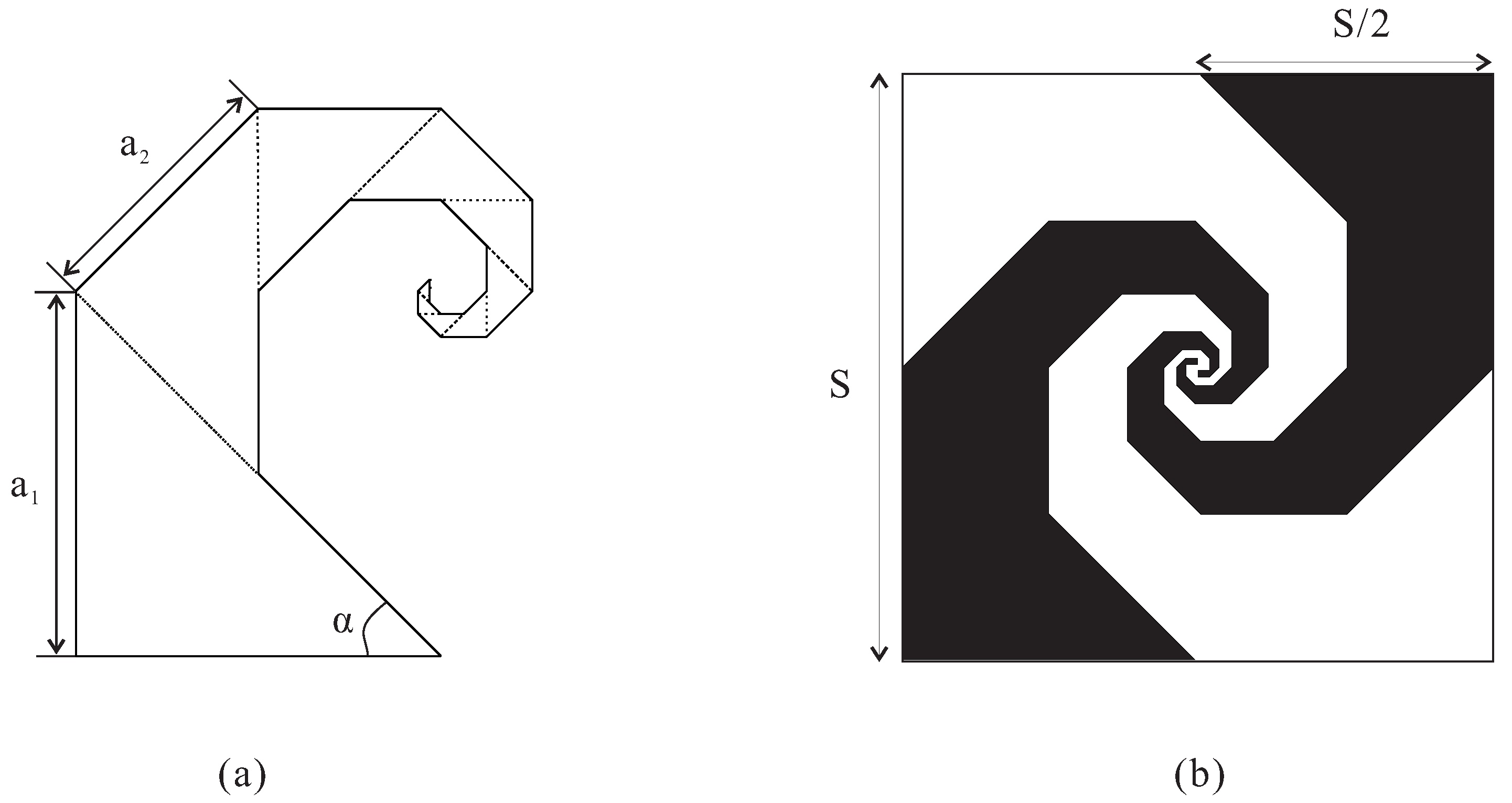
Figure 2.
Geometry of the proposed antenna: (a) 3-D view; (b) Open-state face; (c) Short-state face; (d) Expanded view.
Figure 2.
Geometry of the proposed antenna: (a) 3-D view; (b) Open-state face; (c) Short-state face; (d) Expanded view.

Figure 3.
Input impedance of the proposed antenna as simulated by a lumped port.
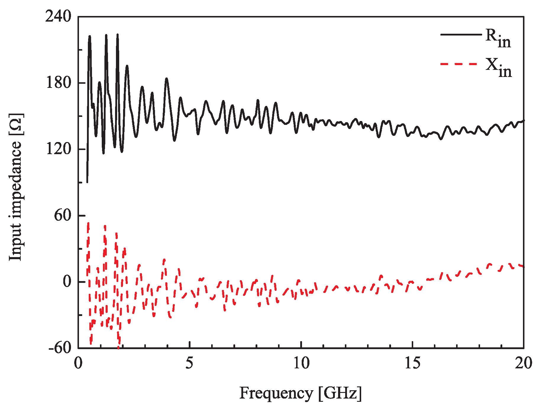
Figure 4.
Geometry of the proposed balun: (a) Top side; (b) Bottom side.

Figure 5.
Photographs of the proposed balun: (a) Top side; (b) Bottom side.
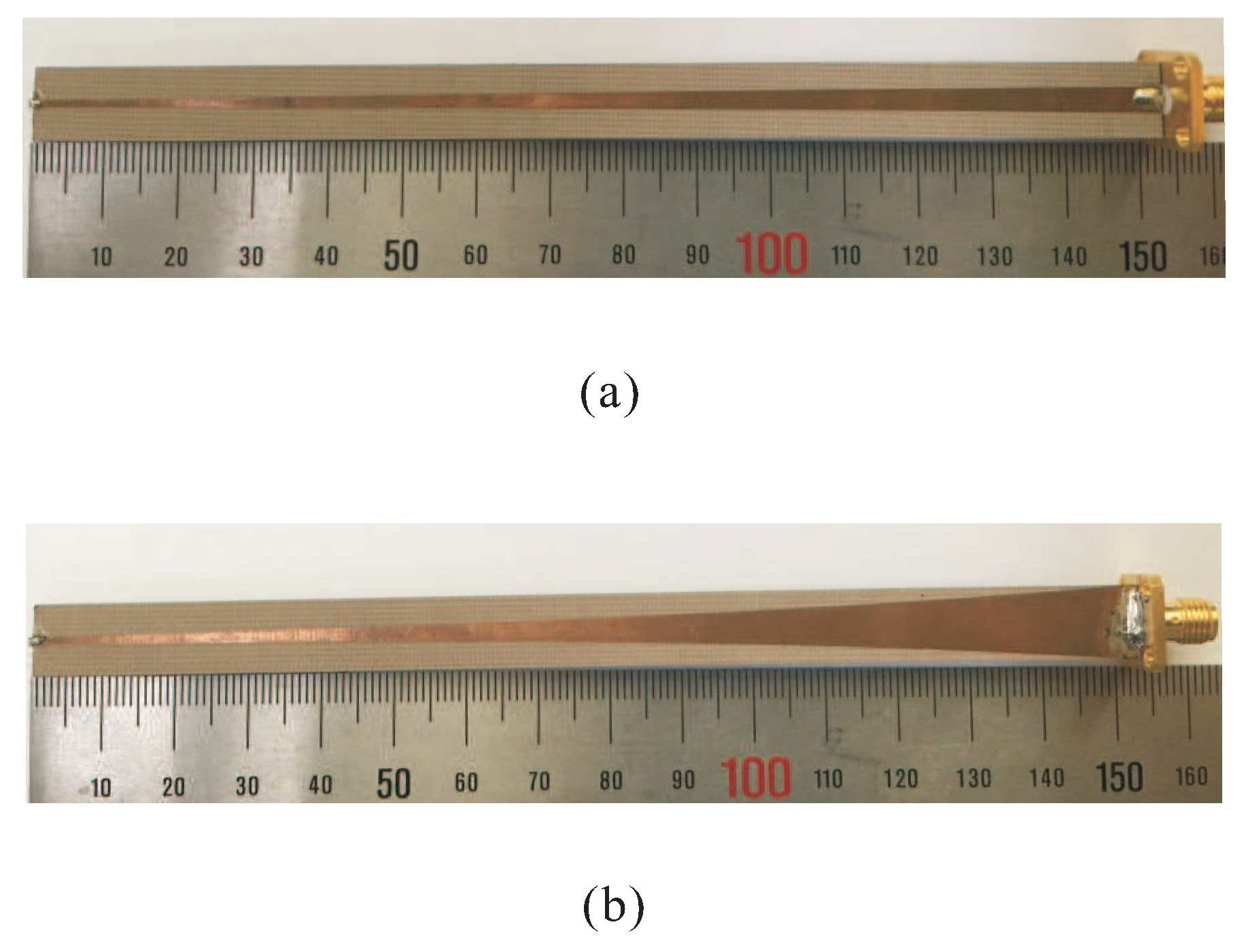
Figure 6.
Photograph of the proposed antenna.
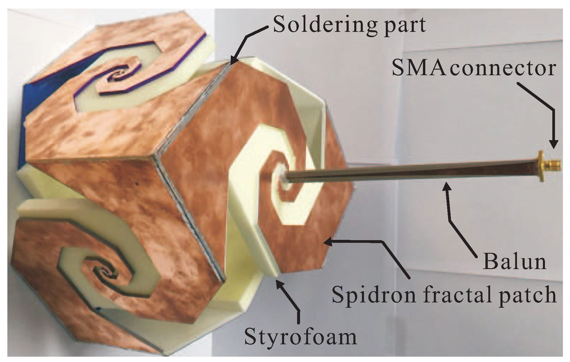
Figure 7.
Simulated and measured reflection coefficients of the proposed balun.
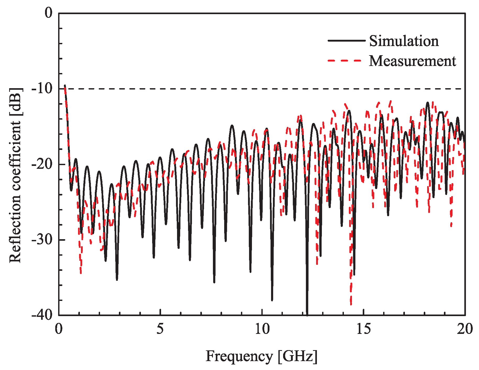
Figure 8.
Simulated and measured reflection coefficients of the proposed antenna.
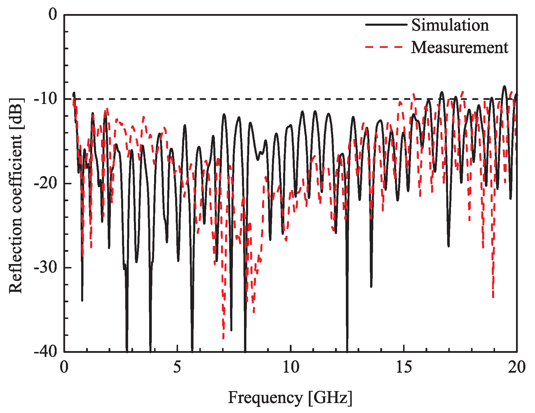
Figure 9.
Measured peak gain of the proposed antenna.
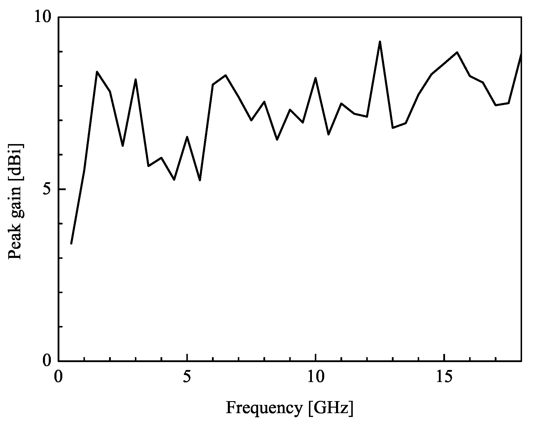
Figure 10.
Measured radiation patterns of the proposed antenna at (a) 0.5 GHz; (b) 8 GHz; (c) 15 GHz.
Figure 10.
Measured radiation patterns of the proposed antenna at (a) 0.5 GHz; (b) 8 GHz; (c) 15 GHz.
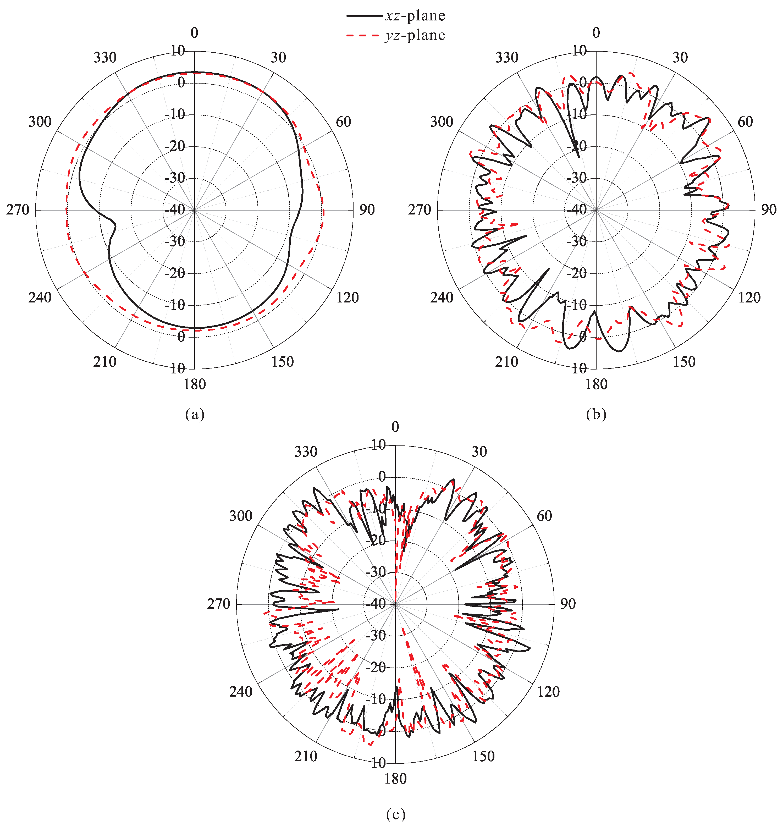
Figure 11.
Simulated radiation efficiency of the proposed antenna.


Table 1.
Comparison of the proposed antenna and 3D antennas in previous studies (note that is the wavelength corresponding to the lowest operating frequency).
Table 1.
Comparison of the proposed antenna and 3D antennas in previous studies (note that is the wavelength corresponding to the lowest operating frequency).
| Description | −10 dB Reflection Ratio Bandwidth (GHz) | Size () |
|---|---|---|
| Monopolar patch antenna [5] | 25.9:1 | |
| Dielectric embedded monopole antenna [6] | 10.7:1 | |
| Fractal monopole dielectric resonator antenna [7] | 20.1:1 | |
| Bow-tie-shaped antenna [9] | 3.77:1 | |
| Printed arrow-shaped antenna [10] | 2.83:1 | |
| Teardrop spherical antenna [12] | less than 10:1 | |
| Proposed antenna | 34.9:1 |
© 2017 by the authors. Licensee MDPI, Basel, Switzerland. This article is an open access article distributed under the terms and conditions of the Creative Commons Attribution (CC BY) license (http://creativecommons.org/licenses/by/4.0/).
Share and Cite
MDPI and ACS Style
Kwon, O.H.; Park, W.B.; Lee, S.; Lee, J.M.; Park, Y.M.; Hwang, K.C. 3D-Printed Super-Wideband Spidron Fractal Cube Antenna with Laminated Copper. Appl. Sci. 2017, 7, 979. https://doi.org/10.3390/app7100979
AMA Style
Kwon OH, Park WB, Lee S, Lee JM, Park YM, Hwang KC. 3D-Printed Super-Wideband Spidron Fractal Cube Antenna with Laminated Copper. Applied Sciences. 2017; 7(10):979. https://doi.org/10.3390/app7100979
Chicago/Turabian StyleKwon, Oh Heon, Won Bin Park, Sungwoo Lee, Jong Min Lee, Young Mi Park, and Keum Cheol Hwang. 2017. "3D-Printed Super-Wideband Spidron Fractal Cube Antenna with Laminated Copper" Applied Sciences 7, no. 10: 979. https://doi.org/10.3390/app7100979
Note that from the first issue of 2016, this journal uses article numbers instead of page numbers. See further details here.