Article

Residual Stress and Deformation Analysis in Butt Welding on 6 mm SUS304 Steel with Jig Constraints Using Gas Metal Arc Welding

1
Department of Mechanical Engineering, National Kaohsiung University of Applied Sciences, Kaohsiung 80778, Taiwan
2
Department of Electrical Engineering, Cheng Shiu University, Kaohsiung 83347, Taiwan
*
Authors to whom correspondence should be addressed.
Appl. Sci. 2017, 7(10), 982; https://doi.org/10.3390/app7100982
Submission received: 13 August 2017 / Revised: 20 September 2017 / Accepted: 20 September 2017 / Published: 23 September 2017
(This article belongs to the Special Issue Selected Papers from IEEE ICICE 2017)

Abstract

:
This article proposes a novel method for analyzing residual stress and deformation in butt welding on 6 mm SUS304 stainless steel plates, using MSC.MARC, a commercial finite element method software, to find the best location for jig fixtures that will minimize welding deformation. Simulation and experimental studies show that a distance of 100 mm between the jig center and the welding bead center is best for inhibiting welding deformation when the jigs experience downward displacement at 0 mm on the steel plate; the total displacement is only about 1.1 mm in the case of a 300 × 250 × 6 mm SUS304 steel plate. In addition, a numerical model shows that four jigs with pitches of 200 mm can better reduce welding deformation than six jigs with pitches of 100 mm. The largest residual stress after welding occurs around the weld bead center, and the residual stress away from the welding bead center increases gradually when jigs have been applied on the steel plate to prevent deformation. The reaction force of the jigs on the steel plate has no further effect in reducing deformation. We conclude that commercially available jigs can inhibit deformation during the welding process.

1. Introduction

The thermal energy produced during the welding process in the area around the welding beads is not equally distributed. Contraction is caused by the temperature of the heat affected zone (HAZ)—the area where the filler material is applied to the welding plates—in conjunction with the temperature of the surrounding areas. This internal tension arises from solidification of the filler metal and cooling of the material. When the welding workpiece cools to room temperature, the filler metal and the welding beads respond differently, leading to a problematic contraction on the welding plate. This results in high residual stress around the area where the heat affects the welding beads and the workpiece, causing a permanent deformation to offset the internal stress that the welding produces on the plate. If such deformation cannot be prevented, the strength of the workpiece will likely be compromised, at best reducing the lifespan of the material and at worst causing serious accidents.
Due to requirements regarding welding speed, welding quality, and plate thickness (3–100 mm or greater), gas metal arc welding (GMAW) is generally adopted in practical applications. A shielding gas is used to protect against melting pools during welding. When workpieces are melted and joined together, the welding beads are subjected to a high temperature from a highly concentrated heat source, causing deformation. The application of jig fixtures is the most common method to reduce such deformation of the workpiece. Many researchers have worked on finding solutions to reduce welding deformation. Ueda and Yamakawa [1] suggested using the finite element method (FEM) to simulate a thermoplastic phenomenon during welding. Ando et al. [2] studied pipe welding, and applied an outside heat source to the welding tube to reduce residual stress. They were able to reduce the residual stress distribution and thereby decrease workpiece deformation. Wang et al. [3] found that applying a linear heat source yields significant deformation, which is detrimental for large-scale structures. Ueda et al. [4] applied a linear heat source opposite the welding arc to reduce buckling and distortion. Guan et al. [5] studied the application of low stress and no distortion (LSND) surface-plate welding to prevent buckling distortion in thin-walled structures. A method called dynamically controlled LSND has been proposed to greatly reduce residual stress and buckling in flat-position welding by applying a cooling source (between a low temperature and a cold temperature) to the back of the welding arc [6]. Mochizuki et al. [7] applied a cooling source on T-butt welding workpieces, and thus significantly reduced deformation. Schenk et al. [8] applied jigs to T-butt welding as well as lap-joint welding and found that the jigs greatly reduced residual stress and deformation. Ziaee et al. [9] found that adding outside welding to sheet metal welding greatly reduced buckling, but it was impossible to eliminate buckling completely. Hajduk et al. [10] researched manual and machine-controlled spot welding in the automotive industry to investigate how jig attachments could control deformation. Park et al. [11] found that applying pressure to the four corners of a workpiece could inhibit welding deformation. Deng and Kiyoshima [12] used the FEM to predict welding residual stresses in a SUS304 girth-welded pipe induced by heating with a tungsten inert gas arc welding torch. Gua et al. [13] studied laser welding in 13 mm thick high-strength steel in the two-dimensional (2D) position to reduce welding defects in the flat welding position. The fluid dynamic simulation results showed that an appropriate balance between surface tension, hydrostatic pressure (gravity), and recoil pressure from the metal vapor could be achieved to assist the welding. Nezamdost et al. [14] investigated the temperature distribution and residual stress in submerged arc welding for pipeline steel by using the Goldak model and considering thermophysical material properties. The proposed 2D axis-symmetric model could be employed to simulate thermal cycles and welding residual stress in test steel. Using jigs to inhibit deformation is currently the most common method in mechanical welding. However, apart from Ma et al. [15] applying jigs to common flat steel plates of type SS400, not much research has been conducted using simulations to discuss the relationships between jig position and plate deformation.
In the present study, we used the finite element analysis software MSC.MARC to analyze, test, and discuss the residual stress and deformation on a workpiece when a jig fixture is or is not applied. We then propose the best position for applying a jig fixture to prevent welding deformation in a workpiece.

2. Methods

Welding is generally considered a complex mechanical, non-linear phenomenon. From the macroscopic perspective, welding problems are related to heat, heat transfer, and solid elastic–plastic mechanical issues. However, at the microscopic level, problems are also connected with the welding plate material, the filler material, and their solidification relationship. The present research focuses on the macroscopic level to analyze and discuss the welding process. Welding is a thermomechanical coupling problem. As it is very difficult to analyze a solid-bodied elastic–plastic energy problem with linear partial differential equations, it is highly unrealistic to seek analytical solutions in this way. Scientists and engineers therefore have found methods that chart a middle course between mathematical theory and applied science by developing numerical analysis that yields results close to analytical ones, including the finite difference method (FDM), the boundary element method (BEM), the boundary domain integral method (BDIM), the FEM, and the finite volume method (FVM).
In GMAW, an electric arc is produced between the consumable wire electrodes and the workpieces, heating the metal of the workpieces and thereby melting and joining them. The welding pool thus formed has a heat flux moment, which transposes heat to the welding workpieces, causing counteractive movement. The entire welding process is therefore strongly influenced by the movement of heat, and simulation using numerical analysis is crucial for obtaining accurate data. Krutz et al. [
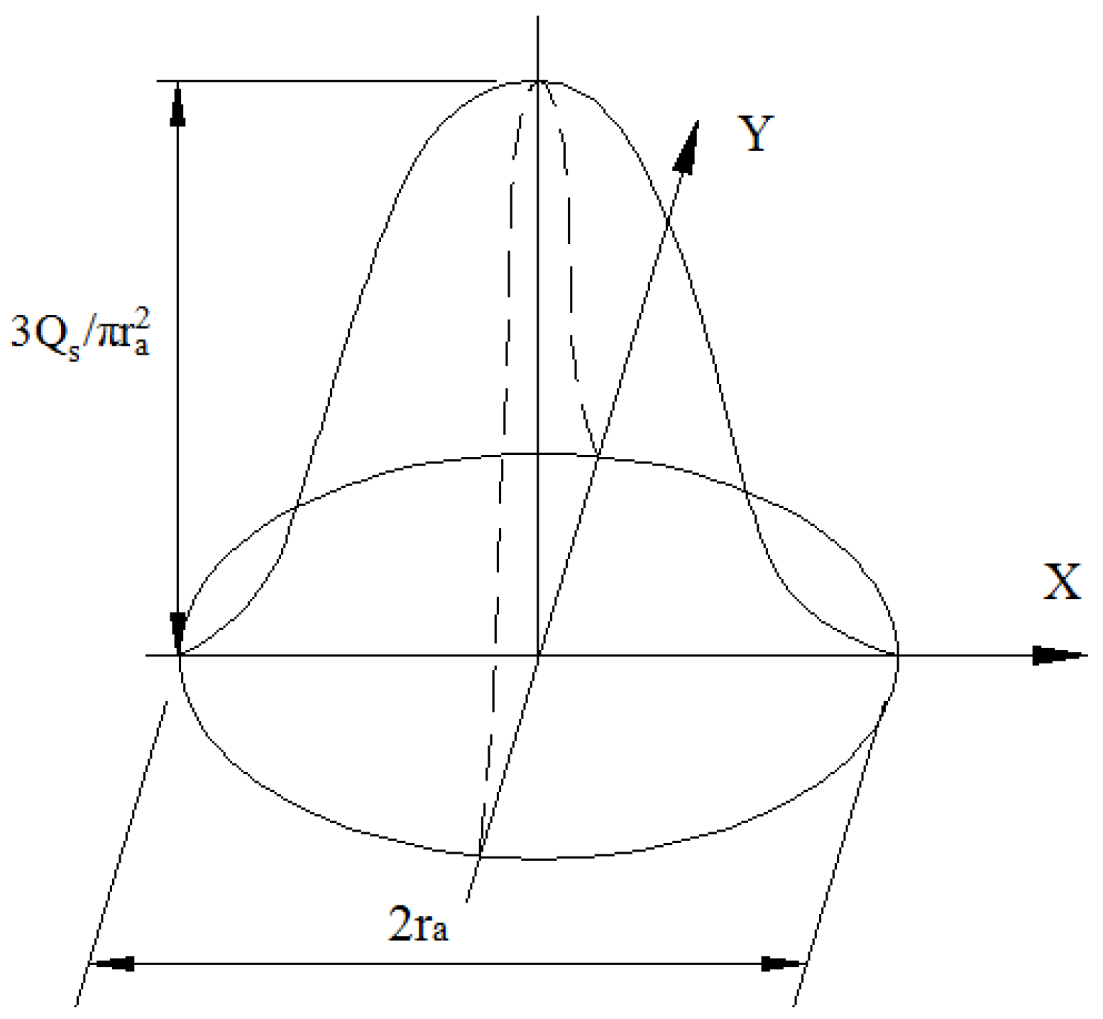
16] combined the Gaussian normal heat source distribution model with the finite element method to simulate the welding process. The Gaussian normal heat source distribution model is the most extensive application of heat source analysis for flat welding (Figure 1); its equations are:
Q s = η U I
q ( x , y ) = 3 Q s π r a 2 e ( 3 r 2 r a 2 )
where: ra is the radius of a heat spot and represents a heat strength of 95% for electronic arc welding applied to a workpiece; r is the radius of the welding heat source; q(x,y) stands for the heat density at a distance r from the heat center; Qs is the amount of heat distribution during welding; and η is the efficiency of the welding heat.
In 1983, Eagar and Tsai [17] were the first to study three-dimensional (3D) moving ellipsoid heat sources. This form of heat source model completely overcomes the weaknesses of the 2D Gaussian normal distribution heat source model, so even heat deep beneath the welding surface can be simulated. The result is similar to an actual electric arc welding outcome because it is not a simple surface analysis of the heat situation at the welding bead. The proposed equation is
q ( x ,   y ,   z ) = 6 3 Q s abc π π e ( 3 x 2 c 2 + 3 y 2 a 2 + 3 z 2 b 2 ) .
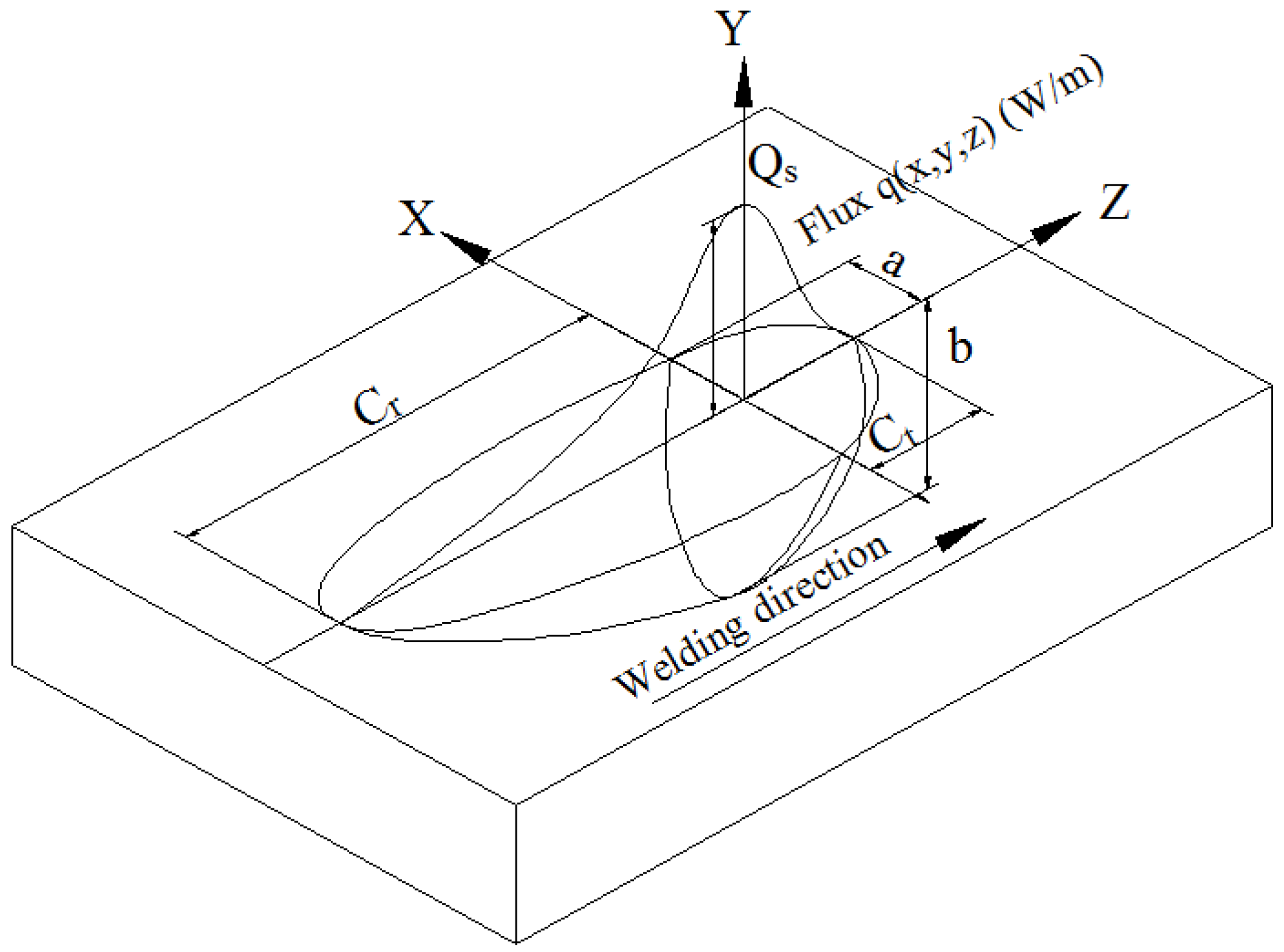
However, experimental results have shown that the temperature gradient is very steep for the first half of the welding pool but not for the second half. Goldak et al. [18] therefore made the welding heat source ellipsoid, combining two half ellipses into an ellipsoid of Gaussian heat source distribution, as shown in Figure 2. The modified equations are
q f ( x ,   y ,   z ) = 6 3 f f Q s a b C f π π e ( 3 x 2 c f 2 + 3 y 2 a 2 + 3 z 2 b 2 )
q r ( x ,   y ,   z ) = 6 3 f r Q s a b C r π π e ( 3 x 2 c r 2 + 3 y 2 a 2 + 3 z 2 b 2 )
f f + f r = 2 ,
f f = 2 1 + C r / C f ,   f r = 2 1 + C f / C r ,
where: Qs is the heat distribution of the welding heat source; qf(x, y, z) is the first half of the ellipsoid heat distribution amount at a point (x, y, z); qr(x, y, z) is the second half of the ellipsoid heat distribution amount at a point (x, y, z); a is the half width of the distributed heat source; b is the welding heat source depth; cf is the length of the first half of the ellipsoid; cr is the length of the other half of the ellipsoid; ff is the strength distribution on the first half of the ellipsoid; fr is the strength distribution on the other half of the ellipsoid; and x, y, and z are the moving coordinates of the heat source.
Since the welding heat source in MSC.MARC software adopts the ellipsoid Gaussian heat source distribution model depicted in Figure 2, the welding simulation for a moving straight line and for a heat source applied in a single direction can be directly used in a simulation study. However, if the heat source spreads in a non-linear pattern or does not conform to the ellipsoid Gaussian normal distribution, another subroutine should be designed and inserted in MSC.MARC to play the role of this heat source [
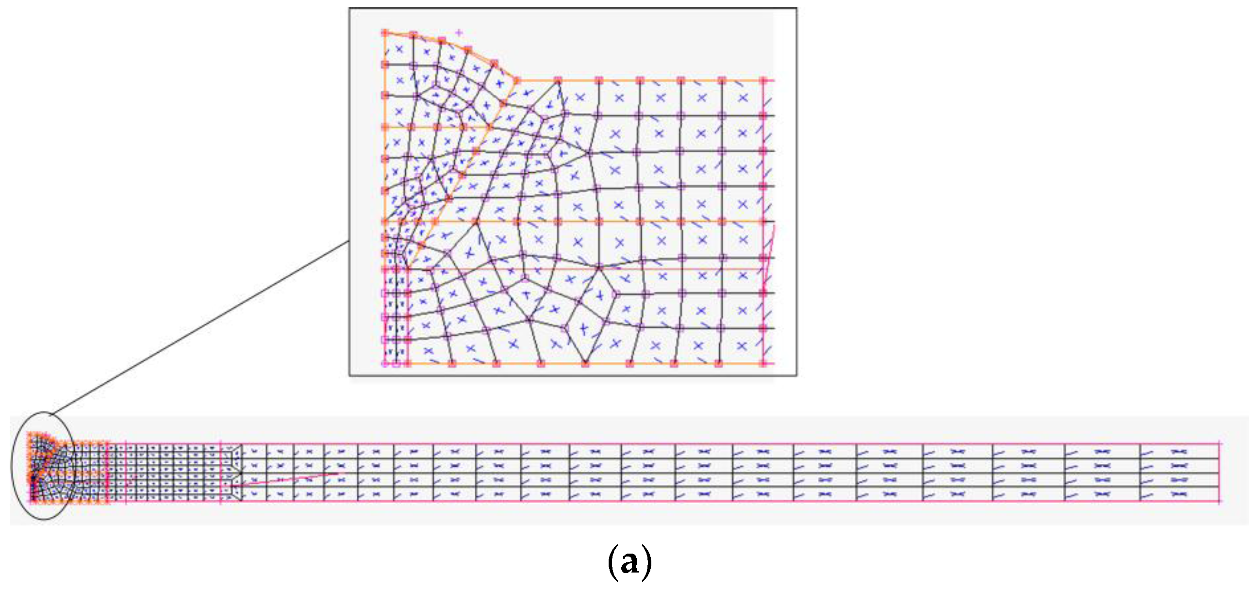
19]. Our research studies the simulation of single-V butt welding using two steel plates 300 × 125 × 6 mm of type SUS304 with a 60° groove angle. The dimensions of the plates follow the specifications in AWS D1.6:2007—Structural Welding Code—Stainless Steel for a horizontal sample plate welding simulation, as shown [20]. Since the geometric shape of the welding pieces is quite simple, inserting a 2D drafting frame designed by Solidwork into MSC.MARC was sufficient to build a grid plan. After a 2D grid was generated for all four sides, additional mesh density was added to the area of the welding bead, as shown in 
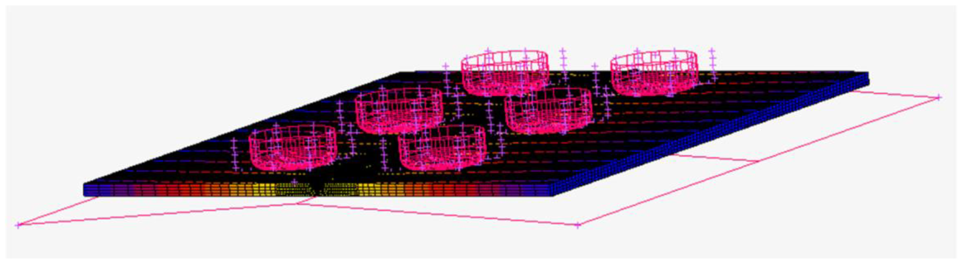
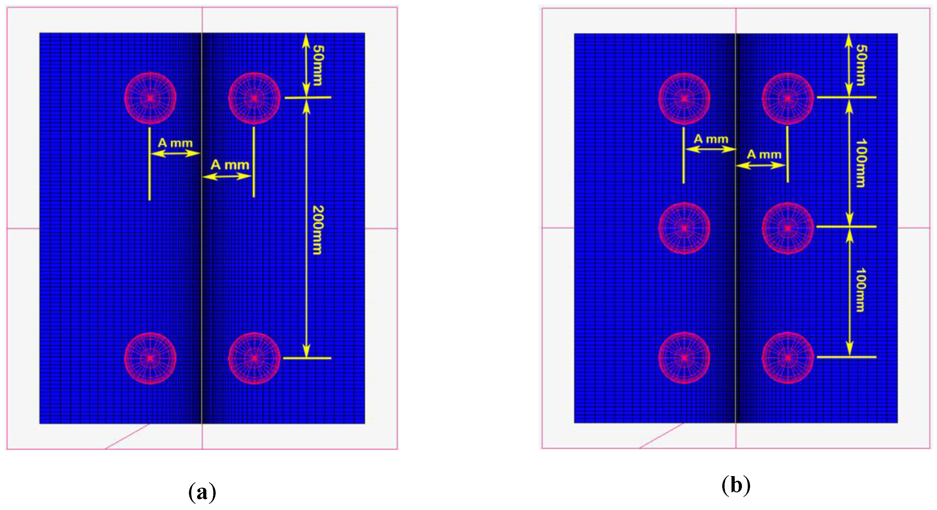
Figure 3a,b. Because welding deformation can be partially inhibited by adding jigs to the workpieces, this applied downward pressure is also incorporated into the simulation (Figure 4). Note that the jig model is considered a rigid body.
The simulation assumptions for this article are as follows: (1) the thermal and mechanical characteristics of the welding test pieces of type JIS SUS304 are equal in all directions [21]; (2) the welding filler material is of the same type as the test pieces [
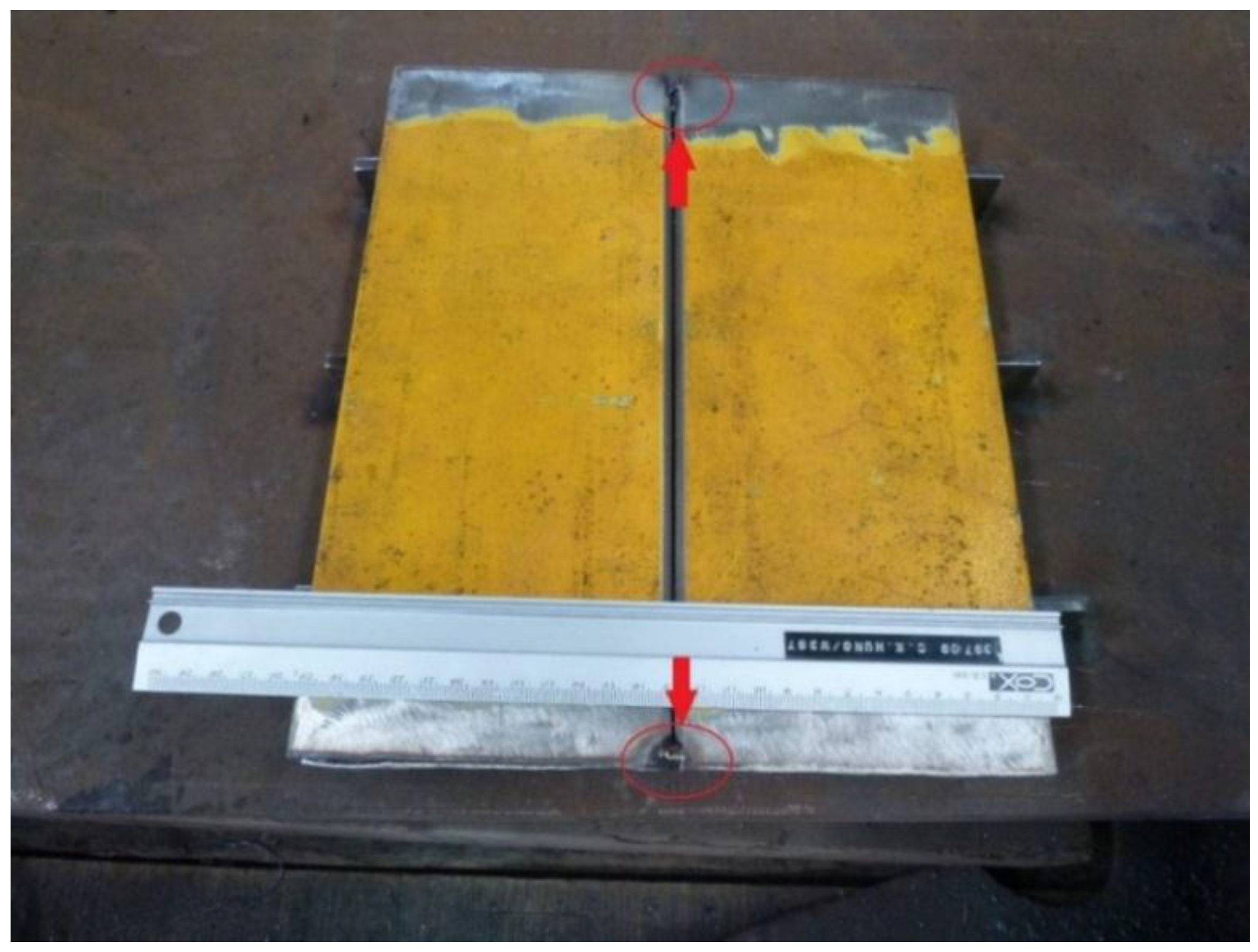
22]; (3) the jigs used to inhibit deformation are steel jigs; and (4) the influence of gravity is ignored. Note that two independent plates are used for the simulation analysis. When a high-calorie welding filler is directly applied to the workpieces, the working plates are easily separated due to thermal deformation problems and cause divergence in the simulation analysis. So, we use a pre-welding spot at both ends of the welding bead to stabilize the simulation analysis for the two separate test pieces, which is similar to the procedure during actual welding. 
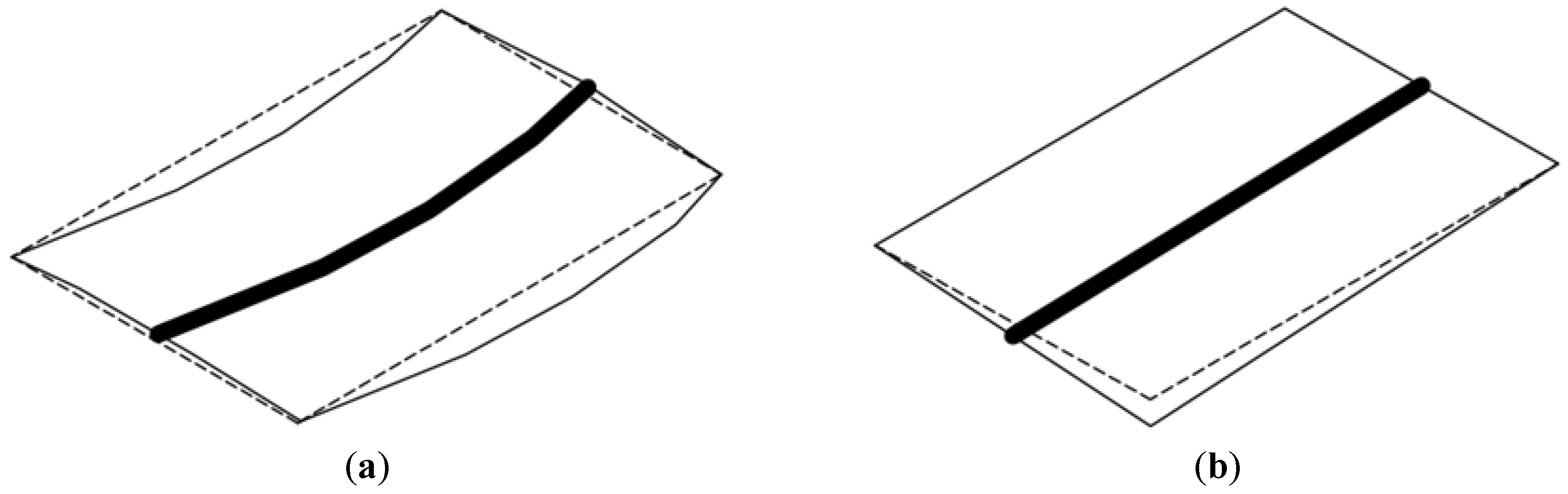
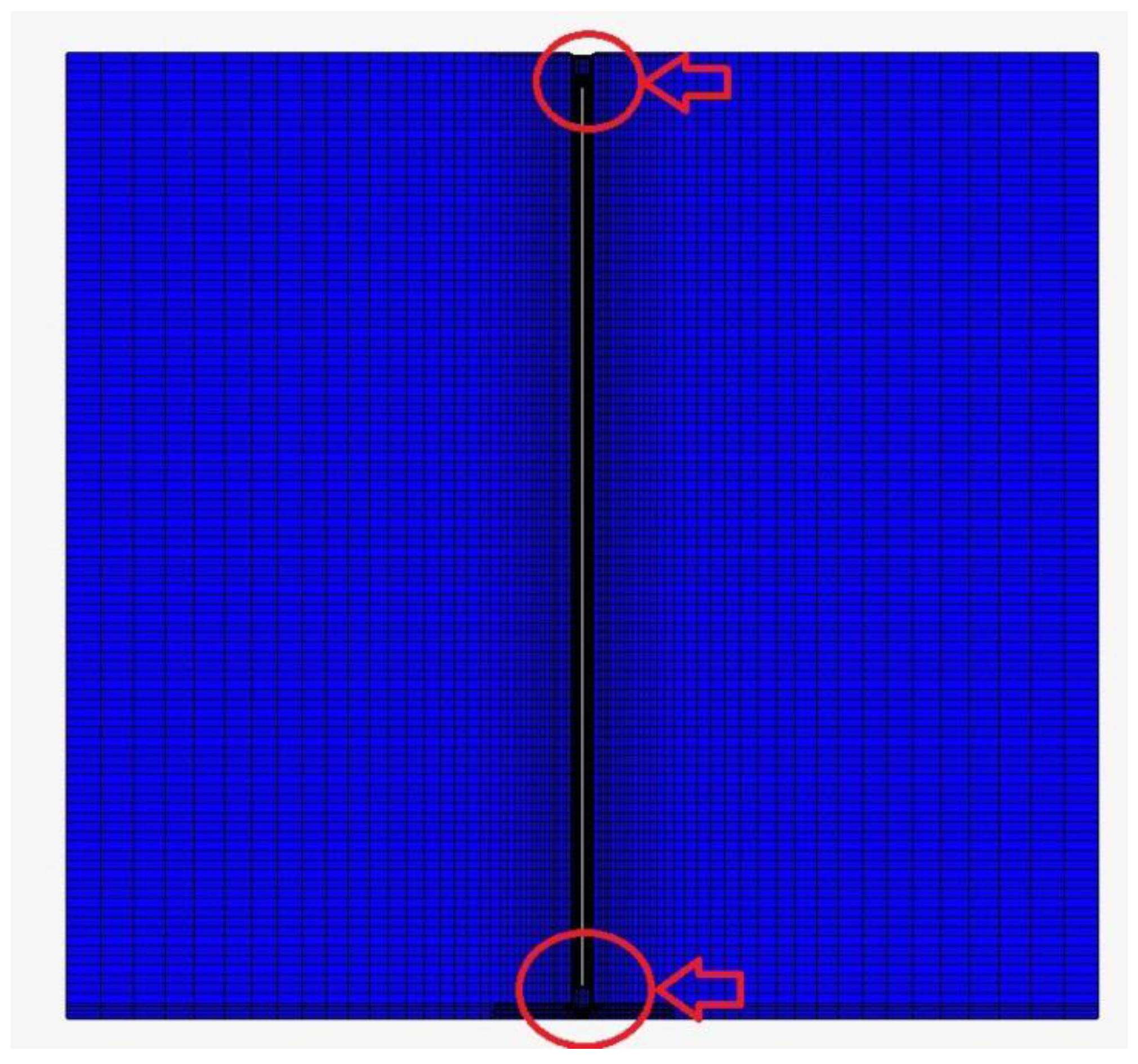
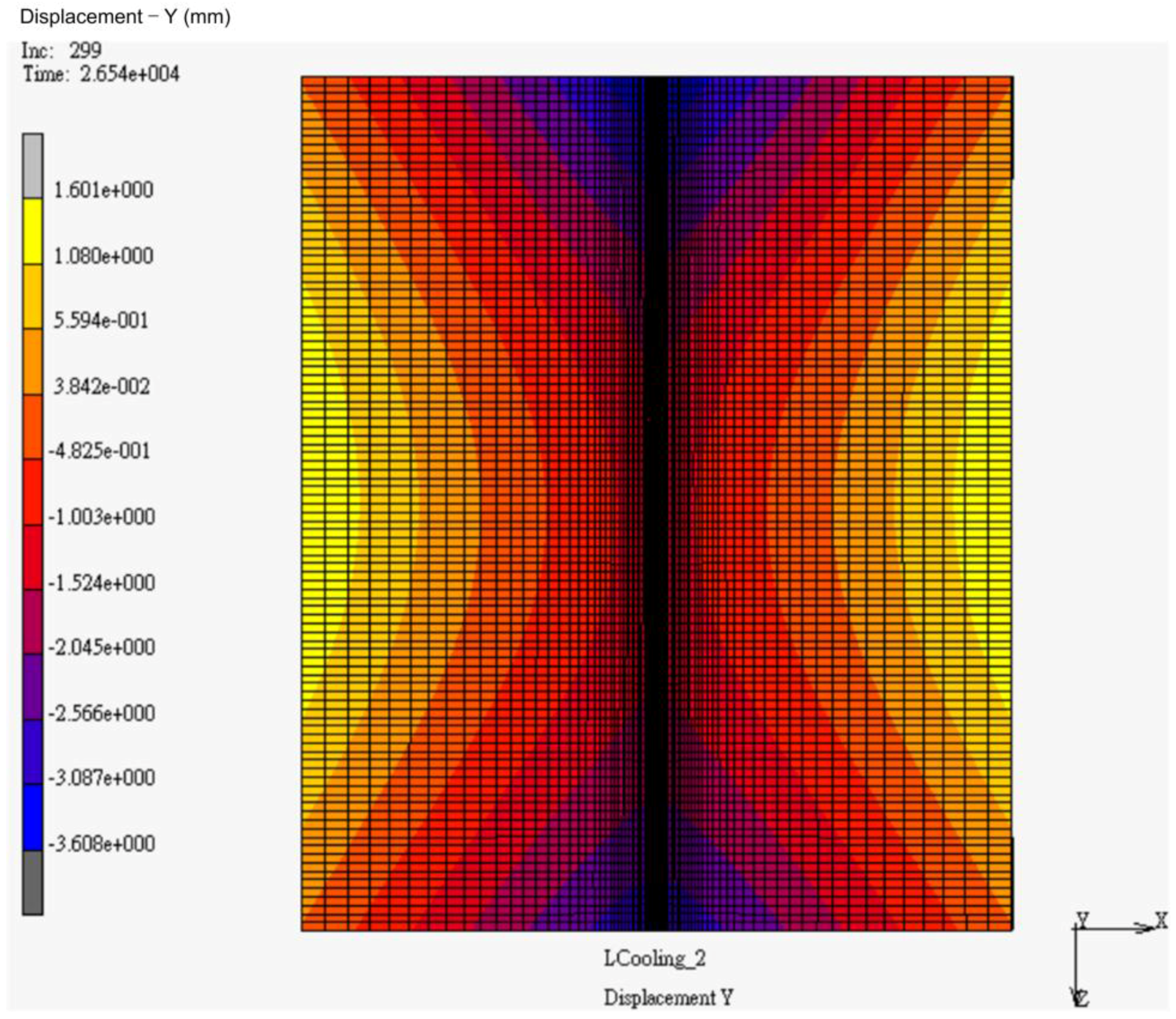
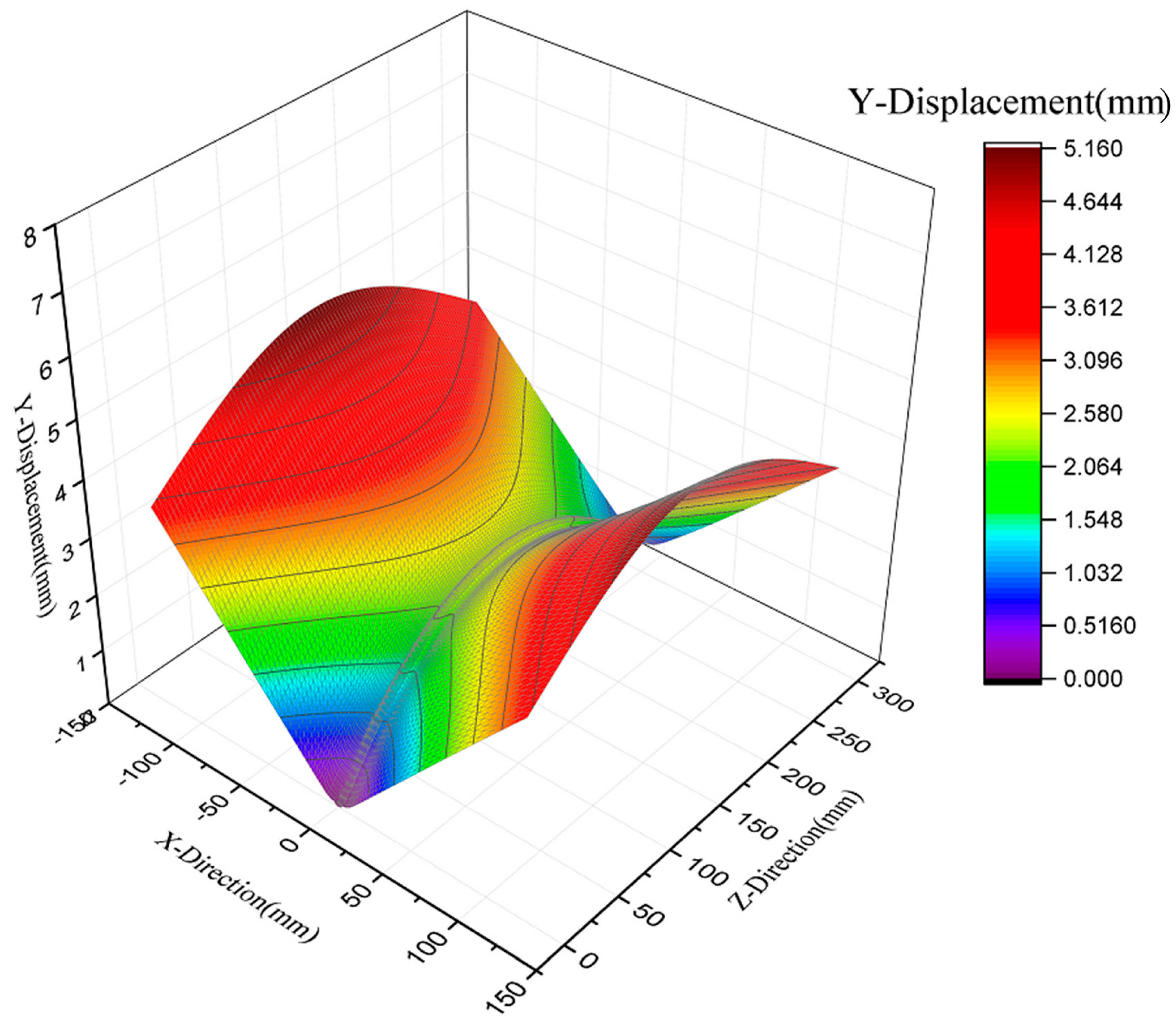
Figure 5 shows the pre-welding spots to attach the two pieces together, and 
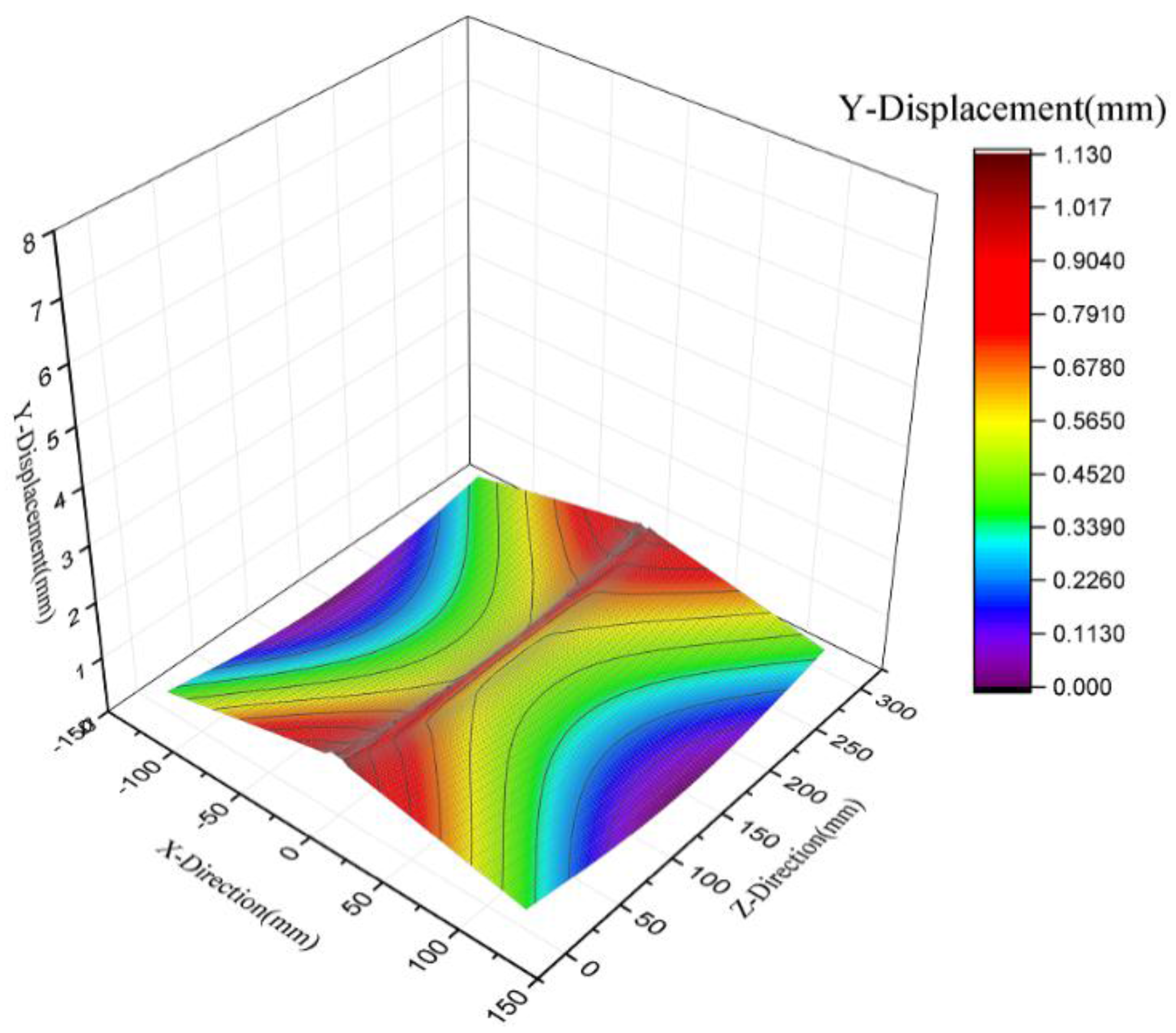
Figure 6 represents the stabilization welding spots inserted into the simulation model, which is a key point in the numerical analysis. In general, the deformation produced on the welded plates is in a saddle-bulge shape vertically and has a twisted formation horizontally, as shown in Figure 7. This study mainly implemented 6 mm thick SUS304 steel plates as realistic test pieces for CO2 GMAW. Table 1 presents the practical welding parameters for the test workpiece with and without jig constraints. Variation in the parameters is due to the manual nature of the welding process. 
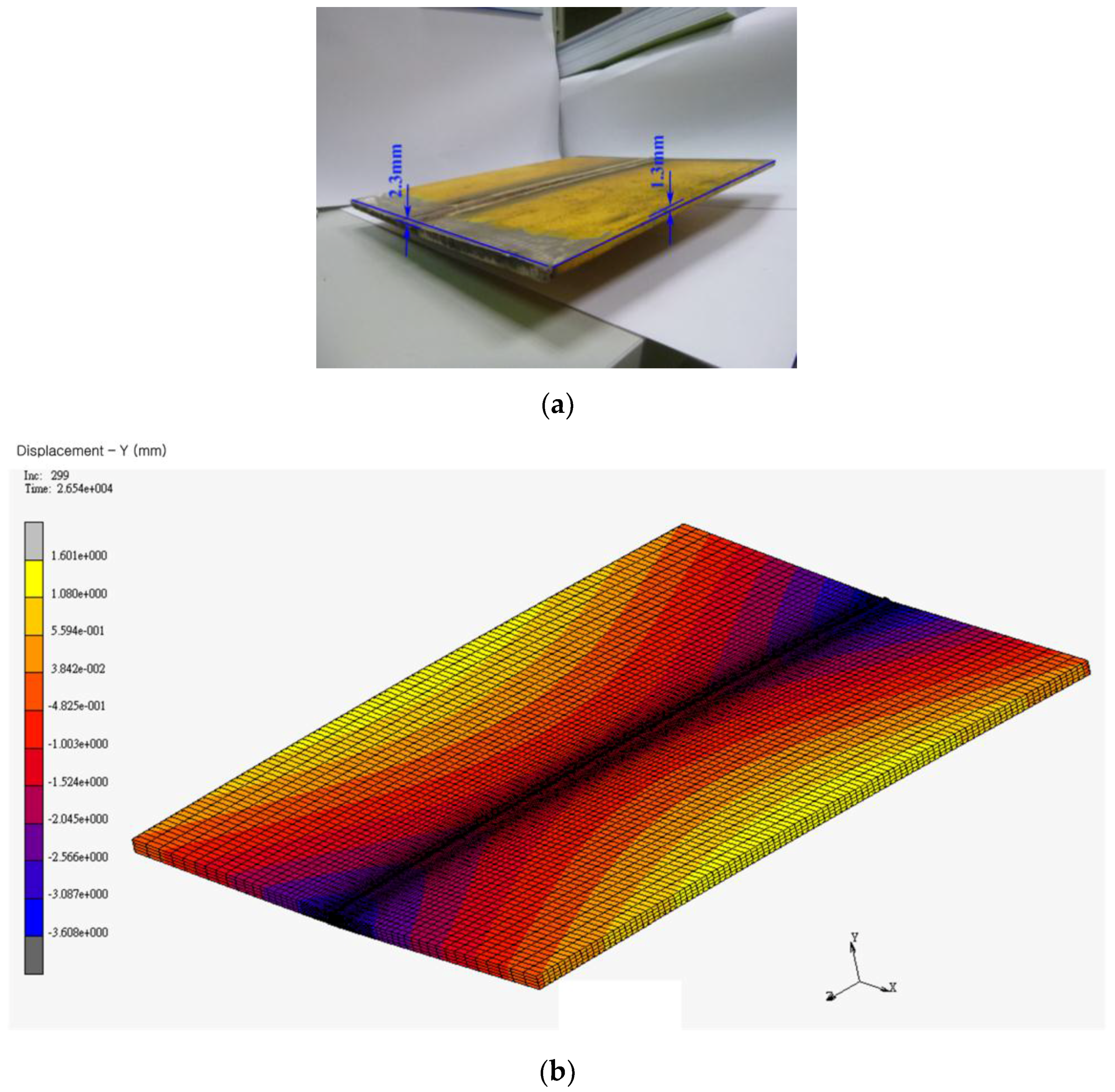
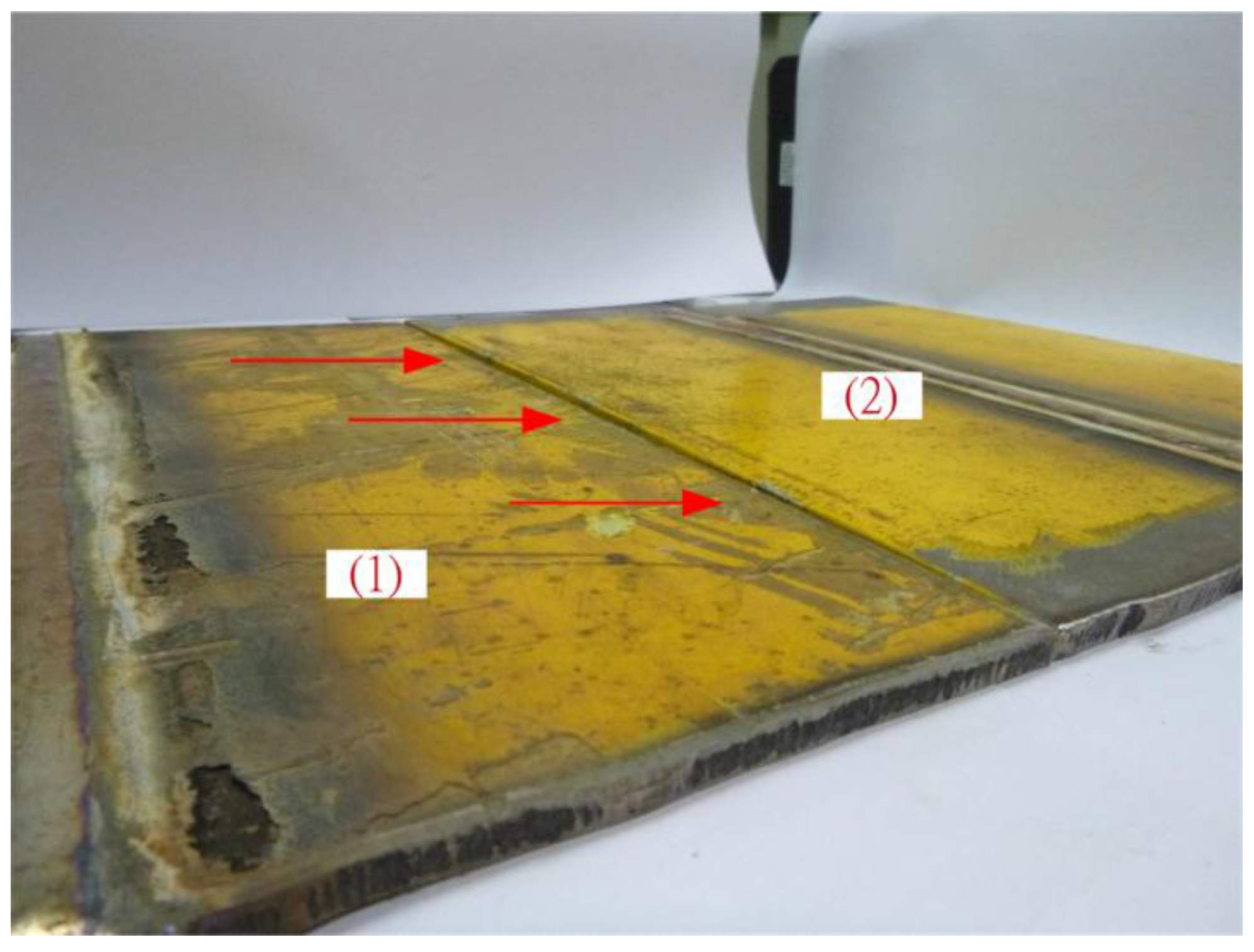
Table 2 shows the simulation parameters of the welding heat source for the test workpiece. Note that the welding process includes two welding passes, and the welding interval is about 30 s. Under the test conditions without jigs, the deformation after cooling to room temperature was identical to what resulted from the numerical simulation analysis, as shown in Figure 8a,b; both displayed a vertical saddle bulge. Figure 9 compares the results for the practical welding process with and without jig constraints, showing that the jig constraints effectively reduced deformation.
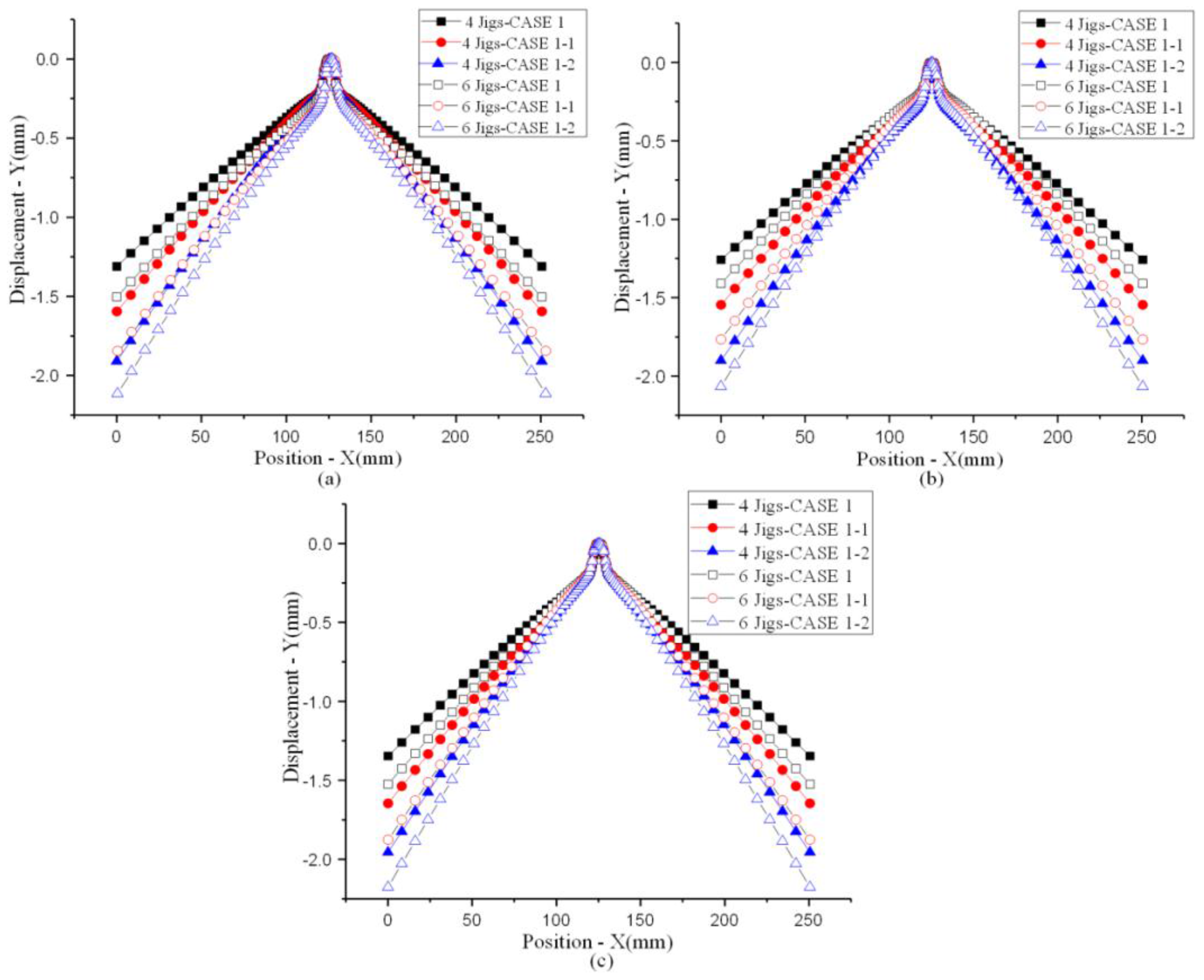
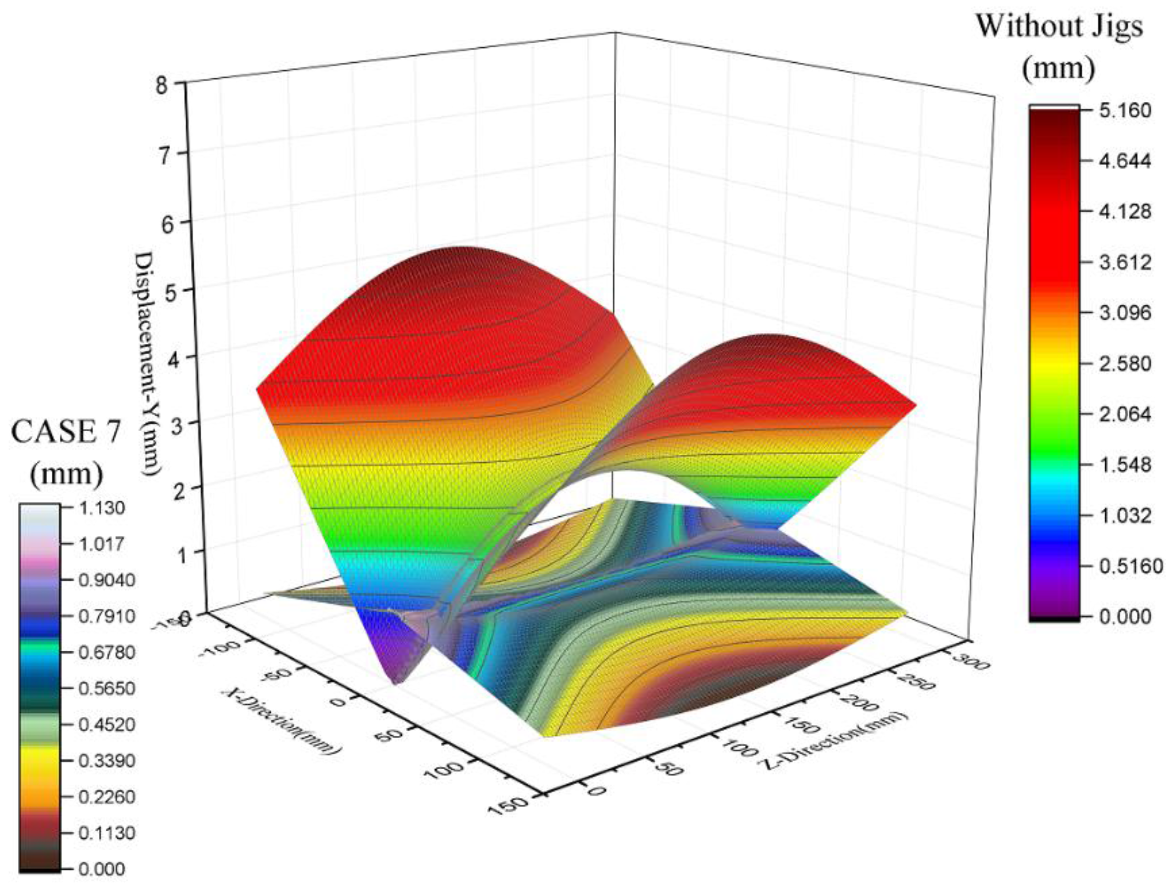
3. Results and Discussion

3.1. Welding Results without Jigs

Figure 10 shows the simulation results of Y-displacement deformation for GMAW without jigs after the workpiece cools to 25 °C. The deformation is large on both sides of the welding bead (see yellow). Figure 11 presents the Y-displacement deformation graph in 3D format and confirms that the overall deformation of the thin plates caused a vertical bulge in the center, front, and back, as well as horizontal twisting. This is quite a complicated deformation and causes major weakening in the welding bead. Considering that construction steel can sustain buckling damage under working stress, the amount of welding deformation that can occur is an important issue in the field of mechanical manufacturing. Figure 12 presents the simulation results for the equivalent von Mises stress situation in a 3D image, showing that the equivalent von Mises stress after welding is very large, even reaching the yield stress of SUS304 stainless steel plates. Since the heat source has the greatest effect at the welding bead and the surrounding area, this can be regarded as equaling the material’s yield stress. Hence, the workpieces must go through a heat treatment procedure to reduce the residual stress. The suggested approaches are solid solution heat treatment for stainless steel and annealing heat treatment for carbon steel.

3.2. Welding Results with Jigs

Here, we consider the use of jigs to inhibit welding deformation, and we further examine residual stress. Figure 13 presents the configurations for four jigs and six jigs, respectively. They are used at a distance from the welding bead center of “A” mm to examine deformation under a depressed displacement of 0 mm, 0.05 mm, and 0.1 mm, respectively. In the simulation, jigs with a depressed displacement of 0 mm are examined for distances of 40, 50, 60, 70, 80, 90, and 100 mm from the jig center to the welding bead center. The results indicate that the X- and Z-displacement are less than 0.1 mm and are considerably smaller than the Y-displacement. Therefore, we hereafter focus only on the Y-displacement. Table 3 presents the simulation cases for the applied jig fixtures. There are a total of 14 cases, of which nine examine the application of four jigs and five examine the application of six jigs, excluding cases 2, 3, 5, and 6. Comparing the results of each case shows the extent to which deformation was inhibited and thus which setup could be used in everyday practical welding applications. Note that the jig-to-jig distances of the applied four and six jigs are 200 and 100 mm, respectively.
To carry out deformation and residual stress analysis, we used discussion lines 1, 2, and 3 in Figure 14 for the cases in Table 3. Figure 15 presents the deformation differences for four and six jigs under a depressed displacement of 0 mm for CASE 1, CASE 4, and CASE 7. Every case has a distance to the welding bead of 40 mm under a depressed displacement of 0 mm. This scenario is used to understand how distance influences welding deformation. From Figure 14, we can see that the deformation results for the applied four and six jigs are very similar in CASE 1, CASE 4, and CASE 7. In CASE 7, the difference is reduced to only 10−2 mm. The simulation shows that jigs within 200 mm result in a very small change in welding deformation.
Figure 16 presents the results of four and six jigs at a distance of 40 mm from the welding bead center with a depressed displacement of 0 mm, 0.05 mm, or 0.1 mm for CASE 1, CASE 1-1, and CASE 1-2. It can be observed that the higher the depressed displacement, the smaller the benefit. The ideal setup for inhibiting deformation appears to be with a depressed displacement below 0 mm. Figure 17 depicts the application of four jigs under a depressed displacement of 0 mm. Careful consideration of the welding deformation in CASE 1 to CASE 7 shows that attaching jigs 100 mm from the depressed center to the welding bead center can effectively suppress welding deformation.
Figure 18 presents a 3D image of the deformation in CASE 7 with jigs. For comparison, Figure 19 shows a 3D image of the deformation in CASE 7 without jigs. It can be clearly seen that welding with jigs considerably reduced the deformation, since the entire displacement difference from highest to lowest for a 300 × 250 mm SUS304 steel plate is only 1.129156 mm. Using jigs to inhibit deformation hence yields remarkable results at low cost.
Next, we examine residual stress when a jig fixture is applied during welding to reduce deformation. Figure 20 compares the equivalent von Mises stress of lines 1, 2, 3, and 4, respectively, for CASE 1, CASE 4, and CASE 7. The equivalent von Mises stress gradually increases in every case. Figure 21 presents the overall equivalent von Mises stress in 3D, and shows that the highest residual stress is at the welding bead; it is also rather large compared with the amount in the neighboring area. This suggests that when jigs are applied to inhibit deformation in welded workpieces, welding needs to be followed up with heat treatment to reduce residual stress, especially in the area around the welding bead. In general, heat treatment should be applied to the entire welded workpiece to reduce the residual stress most effectively. For comparison with the results presented in Figure 21, Figure 22 shows a 3D image of the equivalent von Mises stress for a workpiece welded without jigs. Higher residual stress is evident around the welding bead. However, when the distance of the applied jigs from the welding bead is increased, the residual stress is correspondingly higher, as seen with CASE 7 in Figure 20. We therefore conclude that welding deformation is most effectively inhibited when the distance of the applied jigs from the welding bead is small.

4. Conclusions

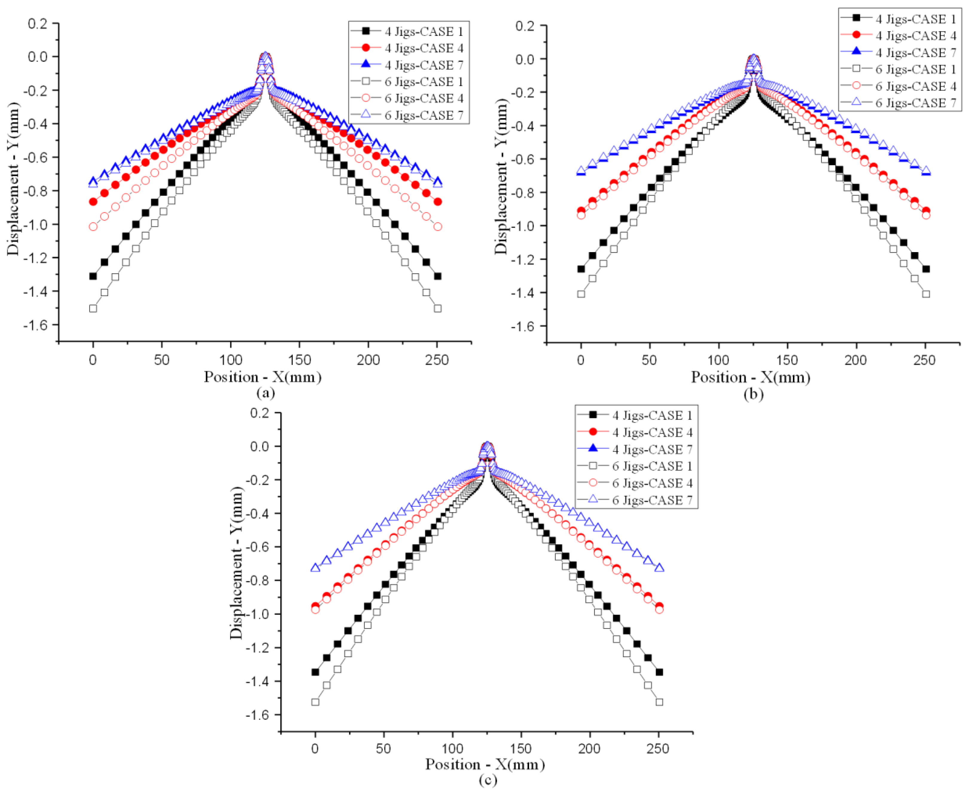
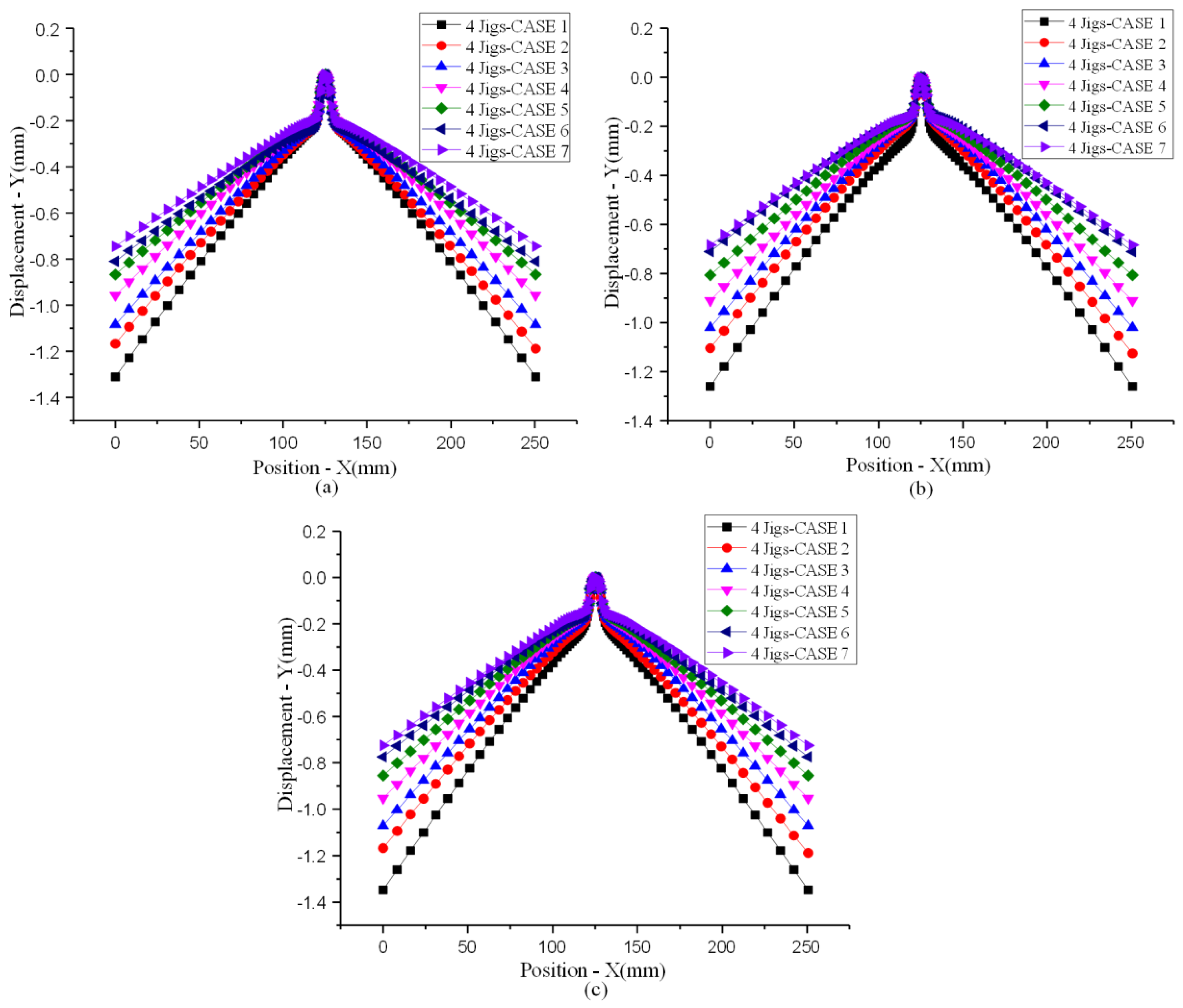
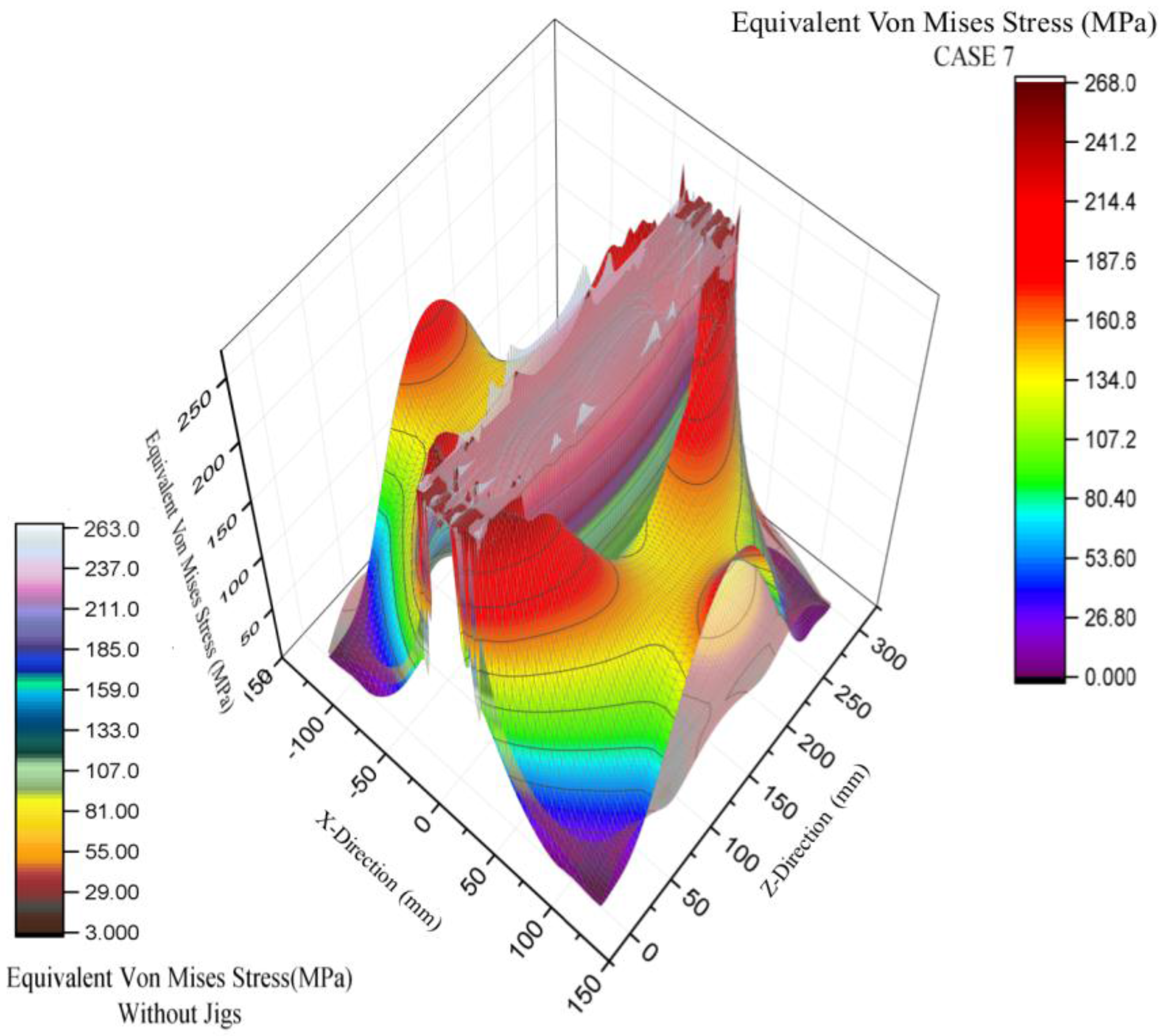
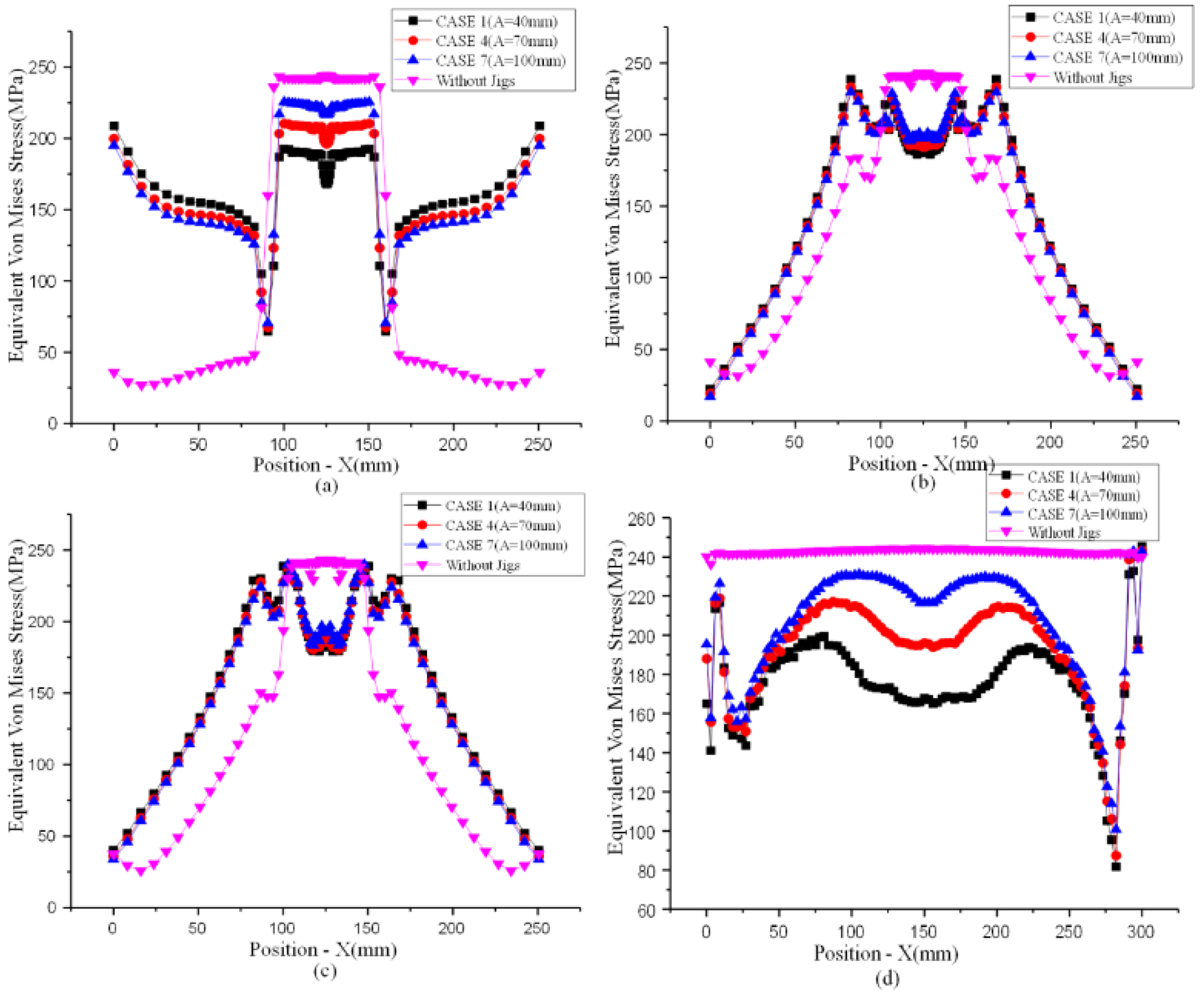
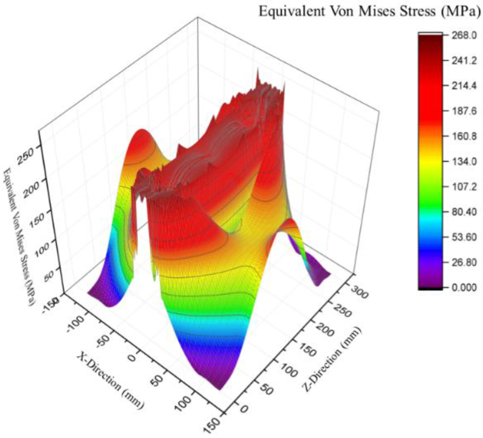
Applying jig fixtures to prevent welding deformation is widely used in industry, but there are currently no standards for how to use jigs, and it is common simply to decide based on personal experience. This study applied the finite element analysis software MSC.MARC to simulate residual stress and deformation in butt welding workpieces on 300 × 250 × 6 mm SUS304 steel with jig fixtures using gas metal arc welding, so as to determine the best location for applying jig fixtures to prevent deformation. Our findings suggest that applying jigs to these steel plates with a depressed displacement of 0 mm produces the best deformation inhibition results for steel plates after welding. They also show that four jigs spaced 200 mm apart inhibit deformation better than six jigs spaced 100 mm apart. The best deformation inhibition results are achieved not when the jigs are attached closer to the welding bead, but when they are attached at a suitable distance from the welding bead. This research suggests that the optimal location for applied jigs is 100 mm from the welding bead, which is similar to actual welding practice. The total difference between the maximum and minimum displacement after welding in the case of 300 × 250 × 6 mm SUS304 steel plates is about 1.1 mm. Regardless of whether or not jigs are applied, the equivalent von Mises stress or residual stress is highest at the welding bead and reaches the yield stress of the welding plates. Adding jigs to inhibit deformation significantly increases the equivalent von Mises stress/residual stress. Therefore, we suggest that to lessen the residual stress, heat treatment should be applied to the area around the welding bead or to the whole workpiece.
This article provides a novel method for analyzing residual stress and deformation in butt welding using the finite element method with a customized subroutine program designed to exactly simulate the actual nonlinear physical phenomenon of this welding process. In the future, we will use this approach to conduct simulation analysis of T-shaped steel plates, a very common form of structural steel used in industry. With the help of custom-designed subroutine programs, the proposed approach can be also extended to analyze multi-layer welding as well as welding with different metals.

Acknowledgments

The authors acknowledge partial financial support under grant no. MOST 106-2221-E-151-017.

Author Contributions

Chao-Ming Hsu conceived and designed the simulations and experiments; Chi-Liang Kung and Cheng-Kuang Hung performed the simulations and experiments; Cheng-Yi Chen wrote the paper.

Conflicts of Interest

The authors declare no conflict of interest.

References

  1. Ueda, Y.; Yamakawa, T. Analysis of Thermal Elastic-Plastic Stress and Strain during Welding by Finite Element Method. Trans. Jpn. Weld. Soc. 1971, 2, 186–196. [Google Scholar]
  2. Ando, Y.; Yagawa, G.; Hayase, Y. Evaluation of Induction Heating Stress Improvement (IHSI) Treatment Applied to Nuclear Primary Piping. Int. J. Press. Vessel. Pip. 1982, 10, 399–406. [Google Scholar] [CrossRef]
  3. Wang, J.; Rashed, S.; Murakawa, H.; Shibahara, M. Investigation of Buckling Deformation of Thin Plate Welded Structures. In Proceedings of the Twenty-first International Offshore and Polar Engineering Conference, Maui, HI, USA, 19–24 June 2011. [Google Scholar]
  4. Ueda, Y.; Murakawa, H.; Ma, N. Welding Deformation and Residual Stress Prevention; Boston: Butterworth-Heinemann, UK, 2012; pp. 209–246. ISBN 978-0-12-394804-5. [Google Scholar]
  5. Guan, Q.; Guo, D.; Li, C. Low Stress Non-Distortion (LSND) Welding—A New Technique for Thin Materials. Trans. Chin. Weld. Inst. 1990, 11, 231–237. [Google Scholar]
  6. Guan, Q.; Guo, D.L.; Zhang, C.X. Dynamic Control of Welding Distortion by Moving Spot Heat Sink. Weld. World 1994, 33, 308–313. [Google Scholar]
  7. Mochizuki, M.; Yamasaki, H.; Okano, S.; Toyoda, M. Distortion Behaviour of Fillet T-Joint during In-Process Control Welding by Additional Cooling. Weld. World 2013, 50, 46–50. [Google Scholar] [CrossRef]
  8. Schenk, T.; Richardson, I.M.; Kraska, M.; Ohnimus, S. A Study on the Influence of Clamping on Welding Distortion. Comput. Mater. Sci. 2009, 45, 999–1005. [Google Scholar] [CrossRef]
  9. Ziaee, S.; Kadivar, M.H.; Jafarpur, K. Experimental Evaluation of the Effect of External Restraint on Buckling Behavior of Thin Welded Shells. Iran. J. Sci. Technol. Trans. B Eng. 2009, 33, 397–413. [Google Scholar]
  10. Hajduk, M.; Semjon, J.; Vagaš, M. Design of the Welding Fixture for the Robotic Stations for Spot Welding Based on the Modular Concept. Acta Mech. Slov. 2009, 13, 30–37. [Google Scholar] [CrossRef]
  11. Park, J.-U.; An, G.; Lee, H.-W. Effect of External Load on Angular Distortion in Fillet Welding. Mater. Des. 2012, 42, 403–410. [Google Scholar] [CrossRef]
  12. Deng, D.; Kiyoshima, S. FEM Prediction of Welding Residual Stresses in a SUS304 Girth-Welded Pipe with Emphasis on Stress Distribution Near Weld Start/End Location. Comput. Mater. Sci. 2010, 50, 612–621. [Google Scholar] [CrossRef]
  13. Guo, W.; Liu, Q.; Francis, J.A.; Crowther, D.; Thompson, A.; Liu, Z.; Li, L. Comparison of Laser Welds in Thick Section S700 High-Strength Steel Manufactured in Flat (1G) and Horizontal (2G) Positions. Manuf. Technol. 2015, 64, 197–200. [Google Scholar] [CrossRef]
  14. Nezamdost, M.R.; Nekouie Esfahani, M.R.; Hashemi, S.H.; Mirbozorgi, S.A. Investigation of Temperature and Residual Stresses Field of Submerged Arc Welding by Finite Element Method and Experiments. Int. J. Adv. Manuf. Technol. 2016, 87, 615–624. [Google Scholar] [CrossRef] [Green Version]
  15. Ma, N.; Huang, H.; Murakawa, H. Effect of Jig Constraint Position and Pitch on Welding Deformation. J. Mater. Process. Technol. 2015, 221, 154–162. [Google Scholar] [CrossRef]
  16. Krutz, G.W.; Segerlind, L.J. Finite Element Analysis of Welded Structures. Weld. J. 1978, 211–216. [Google Scholar]
  17. Eagar, T.W.; Tsai, N.S. Temperature Fields Produced by Traveling Distributed Heat Sources. Weld. J. 1983, 62, 346–355. [Google Scholar]
  18. Goldak, J.; Chakravarti, A.; Bibby, M. A New Finite Element Model for Welding Heat Sources. Metall. Trans. B 1984, 15, 299–305. [Google Scholar] [CrossRef]
  19. MSC.Marc Volume A: Theory and User Information; MSC.Software Corporation: Santa Ana, CA, USA, 2013; pp. 272–274.
  20. Structural Welding Code—Stainless Steel; American National Standards Institute: Miami, FL, USA, 2007; p. 82.
  21. Piekarska, W.; Kubiak, M.; Saternus, Z. Numerical Simulation of Deformations in T-Joint Welded by the Laser Beam. Arch. Metall. Mater. 2013, 58, 1391–1396. [Google Scholar] [CrossRef]
  22. Anca, A.; Cardona, A.; Risso, J.; Fachinotti, V.D. Finite Element Modeling of Welding Processes. Appl. Math. Model. 2011, 35, 688–707. [Google Scholar] [CrossRef]
Figure 1. Gaussian heat source distribution shape ( Q s ).
Applsci 07 00982 g001
Figure 2. Ellipsoid Gaussian heat source distribution model.
Applsci 07 00982 g002
Figure 3. Meshes of the FEM: (a) partial magnification of grid density; (b) grid setup for the test piece.
Applsci 07 00982 g003aApplsci 07 00982 g003b
Figure 4. Welding simulation jig model as rigid body.
Applsci 07 00982 g004
Figure 5. Pre-welding spot to attach the two pieces together for stabilization in the welding process.
Applsci 07 00982 g005
Figure 6. Two pre-welded spots inserted into the simulation model to stabilize the analysis.
Applsci 07 00982 g006
Figure 7. Deformation types in the test plates: (a) vertical saddle bulge; (b) horizontal twisting.
Applsci 07 00982 g007
Figure 8. Deformation without jigs: (a) actual situation; (b) simulation analysis.
Applsci 07 00982 g008
Figure 9. Deformation with and without jig constraints: (1) with; (2) without.
Applsci 07 00982 g009
Figure 10. Gas metal arc welding (GMAW) welding deformation without jigs after cooling to 25 °C.
Applsci 07 00982 g010
Figure 11. Three-dimensional (3D) image of welding deformation without jigs.
Applsci 07 00982 g011
Figure 12. Three-dimensional (3D) image of equivalent von Mises stress for test piece.
Applsci 07 00982 g012
Figure 13. Applied jigs and positions before welding: (a) four jigs; (b) six jigs.
Applsci 07 00982 g013
Figure 14. Discussion lines for deformation and residual stress analysis.
Applsci 07 00982 g014
Figure 15. Y-deformation using an applied jig fixture with a depressed displacement of 0 mm: (a) line 1; (b) line 2; (c) line 3.
Applsci 07 00982 g015
Figure 16. Y-deformation using an applied jig fixture with a depressed displacement of 0 mm, 0.05 mm, and 0.1 mm: (a) line 1; (b) line 2; (c) line 3.
Applsci 07 00982 g016
Figure 17. Y-deformation using an applied jig fixture with a depressed displacement of 0 mm: (a) line 1; (b) line 2; (c) line 3.
Applsci 07 00982 g017
Figure 18. Three-dimensional (3D) image of welding deformation with jigs in CASE 7.
Applsci 07 00982 g018
Figure 19. Three-dimensional (3D) image of welding deformation without jigs in CASE 7.
Applsci 07 00982 g019
Figure 20. Residual stress distribution for (a) line 1; (b) line 2; (c) line 3; and (d) line 4.
Applsci 07 00982 g020
Figure 21. Equivalent von Mises stress 3D image of CASE 7 for the test pieces after welding.
Applsci 07 00982 g021
Figure 22. Equivalent von Mises stress 3D image of CASE 7 with and without jigs.
Applsci 07 00982 g022
Table 1. Welding parameters for the test workpiece.
Without Jig ConstraintsWith Jig Constraints
Welding Current
(A)
Welding Voltage
(Volt)
Welding Time
(s)
Welding Current
(A)
Welding Voltage
(Volt)
Welding Time
(s)
1st welding pass1003030.181102829.78
Welding interval 28.66 30.1
2nd welding pass1003052.571102849.55
Table 2. Simulation parameters of the welding heat source.
a
(mm)
b
(mm)
Cf
(mm)
Cr (mm)Qs
(Watt)
Speed (mm/s)EfficiencyWelding Time (s)
1st welding pass3.55473000100.7530
Welding interval 30
2nd welding pass6258300060.7550
Table 3. Simulation situation using the applied jigs.
Pressure of jig
(mm)
00.050.1
Center Distance
A (mm)
40CASE 1CASE 1-1CASE 1-2
50CASE 2
60CASE 3
70CASE 4
80CASE 5
90CASE 6
100CASE 7

