1. Introduction
FLASH began operation for experiments in the extended ultraviolet (XUV) and soft X-ray regime in summer 2005 as the world’s first short-wavelength free-electron laser (FEL) facility [
1,
2,
3]. Due to its superconducting accelerator technology, FLASH is currently the only high-repetition rate XUV and soft X-ray FEL which can deliver up to 8000 photon pulses per second for experiments, while normal conducting FELs typically run at rates between 10 and 120 pulses per second. Since 2016, after the installation and commissioning of a second undulator line, it has been possible for two experiments to receive a beam simultaneously [
4,
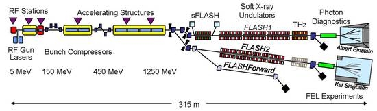
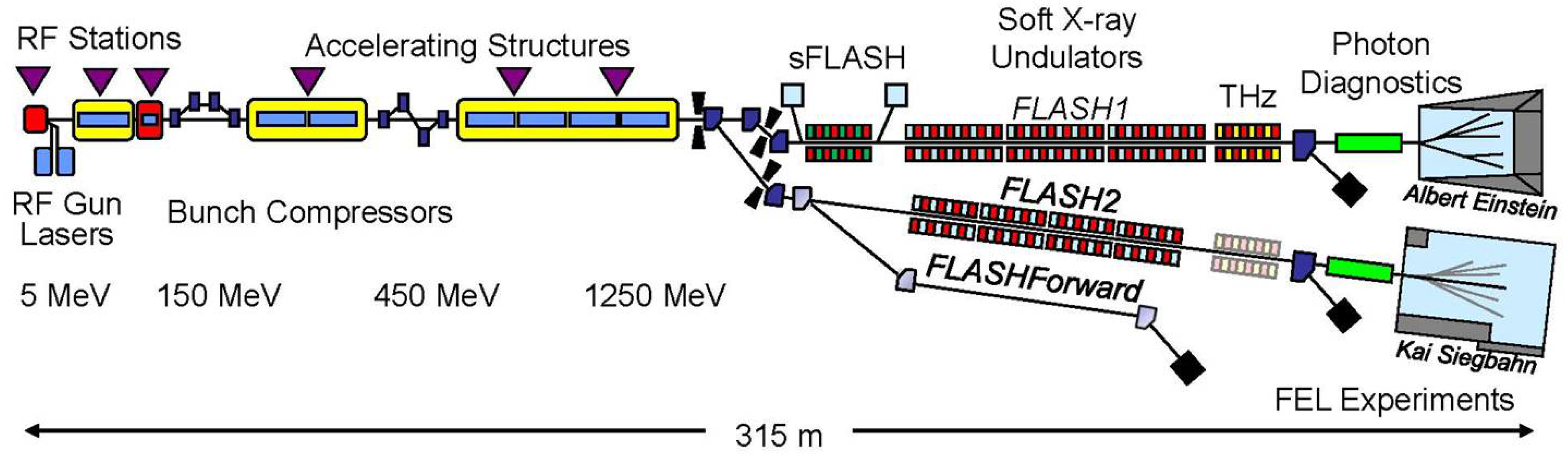
5]. Both FEL lines FLASH1 and FLASH2 (see
Figure 1 for a layout of the facility) are currently run in self-amplified stimulated emission (SASE) mode. The superconducting linac of FLASH is operated in a so-called burst mode and can deliver up to 800 electron bunches in a train with a bunch-to-bunch separation of 1
s and a 10 Hz repetition rate of the bunchtrains. Using two independent photocathode lasers for FLASH1 and FLASH2, the number of bunches from a bunchtrain as well as the intra-train bunch separation going to either of the two FEL lines can be chosen freely, taking into account that 20 to 50
s are needed to switch bunches between FLASH1 and FLASH2 [
4]. The independent photocathode lasers also ensure that the bunch charge can be adjusted individually for the two FEL lines. In combination with fast radio frequency (RF) changes in the time window needed for switching, this enables different compression schemes and hence different pulse durations for user experiments in FLASH1 and FLASH2 [
4]. The most important parameters for FLASH2 are shown in the
Table 1. While the original FLASH1 FEL line is equipped with fixed gap undulators, which requires a change in the electron beam energy to change the photon energy, the new FLASH2 FEL line has variable gap undulators, which allow for scanning of the photon energy. Furthermore, the possibility for tuning the undulators in FLASH2 has opened up the opportunity to implement and test a variety of novel lasing schemes. First results and future plans will be discussed below.
2. Fast Wavelength Scans
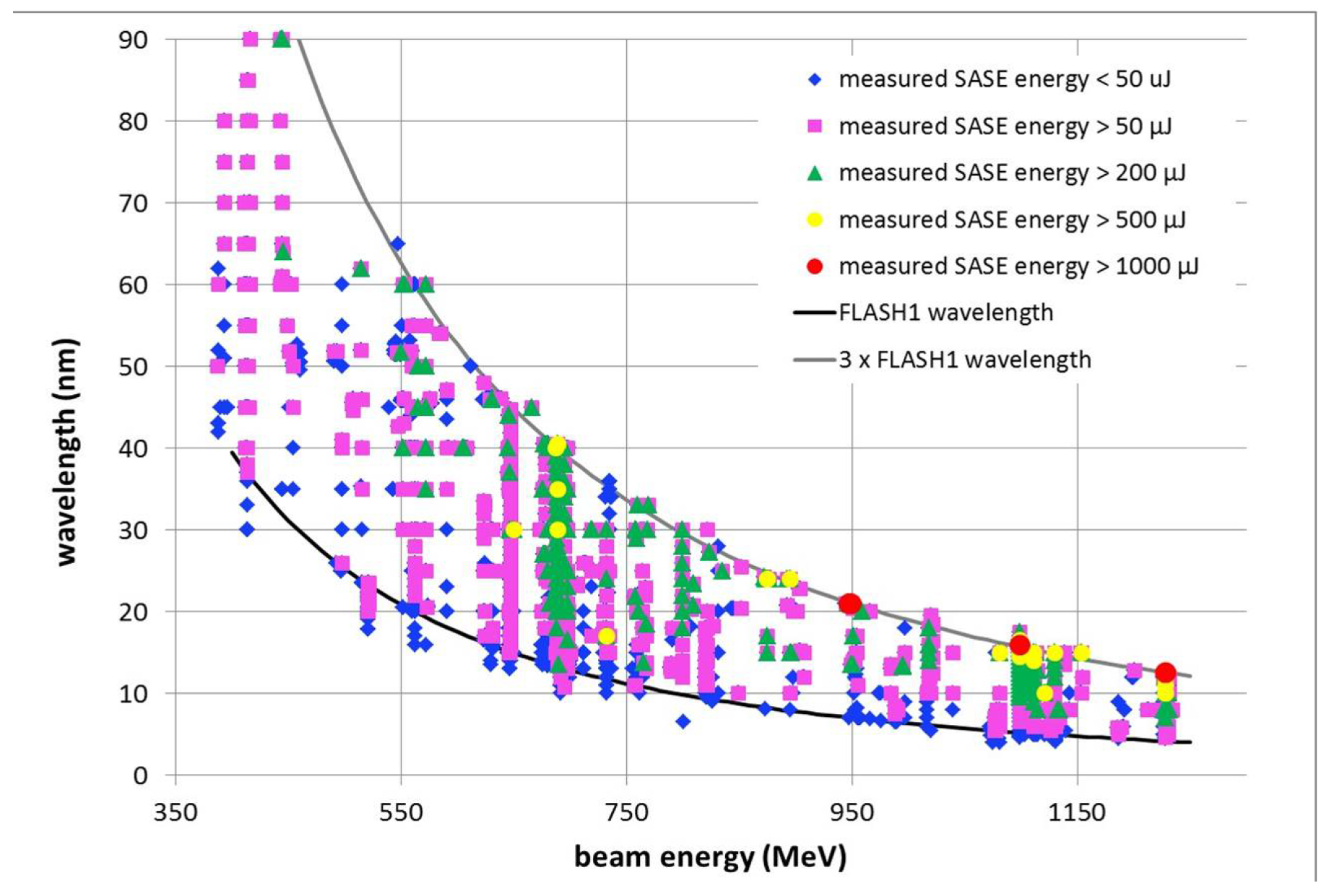
The advantage of variable gap undulators in terms of enhanced flexibility regarding wavelength tunability is demonstrated in
Figure 2 and
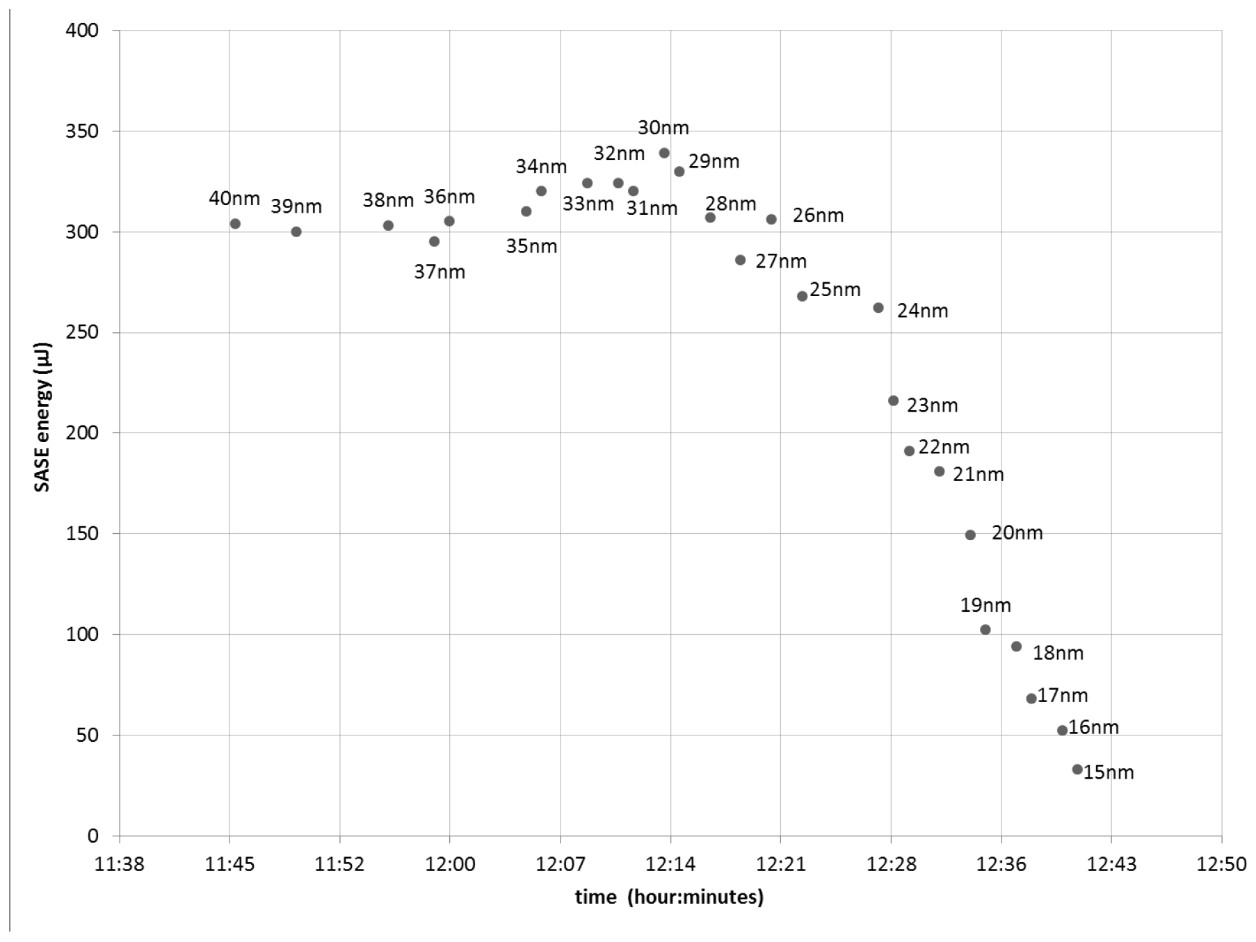
Figure 3 . While the setup of FLASH1 for SASE for a new user experiment at a specific wavelength takes up to several hours because of the required electron beam energy change (with FLASH1 undulators being fixed-gap), setup of FLASH2 can normally be done within one hour or less, depending on the wavelength requested compared to the one at FLASH1. As a consequence, the time it takes for the initial setup of FLASH2 which is done combined with FLASH1, is almost completely determined by the FLASH1 setup time. After that, any change in wavelength and pulse pattern for FLASH2 can be done in a matter of minutes. The longest wavelength that can be reached is produced when the undulators are closed and is given by approximately three times the FLASH1 wavelength for the specific electron beam energy. The minimum FLASH2 wavelength in normal SASE operation depends on the electron beam energy and beam quality, but it is always less than or equal to the FLASH1 wavelength. Therefore, factor of 3 wavelength tunability can be offered at any time. For lower electron beam energies, one can even go significantly beyond that, with up to factor of 4 tunability at lower energies.
Figure 3 shows a fast wavelength scan. In principle, the only action needed to decrease the wavelength is opening of the undulators. In practice, minor orbit corrections of the electron beam are necessary. The online, non-invasive measurement of crucial photon parameters including wavelength, intensity, and beam position need only a few seconds to average before these values are available again. Hence, setting a new wavelength takes only minutes as long as the wavelength change is moderate. In particular, scanning across a photoabsorption resonance is almost as easy as at a storage ring.
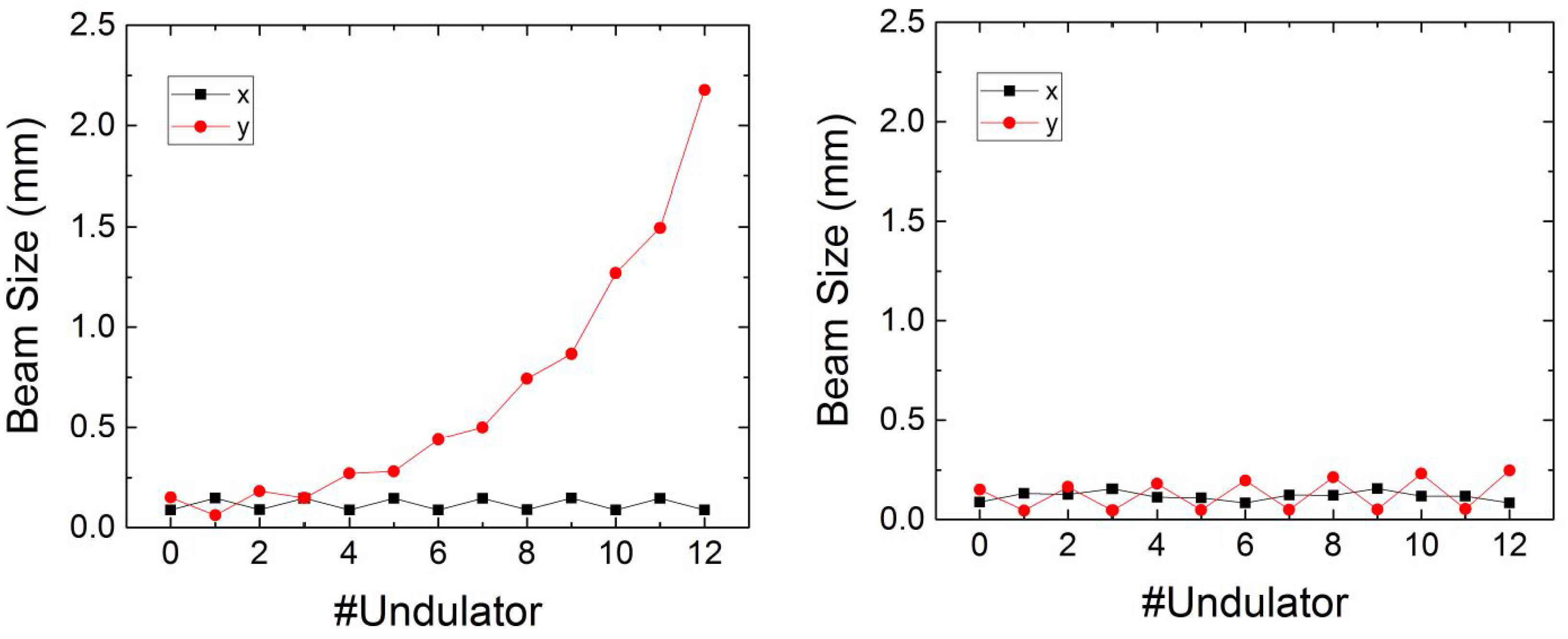
For large wavelength changes, the setup is still fast, but needs further adjustments concerning electron beam optics. For electron beam energies, at which FLASH is operated, the undulator focusing can be rather strong when the undulators are closed. In extreme cases, as shown in simulations in
Figure 4, the focusing becomes so strong that the beam size along the undulator grows and leads to losses unless the focusing is adjusted. Even if these losses would not trigger the machine protection system and consequently switch off the beam, the growing beam size would pose a problem. In this case, the last undulators would no longer contribute to the FEL amplification process, resulting in lower pulse energy. Furthermore, the source point would be no longer in the last undulator, forcing the experiment to either move the instrument or adapt the focusing, assuming that either is possible. Neither solution is straightforward and they can only be performed once the saturation source point is remeasured. At FLASH2, we therefore now adjust the focusing automatically, as shown in the simulations in the right picture of
Figure 4. Theoretically, this would also require a rematching of the electron beam at the undulator entrance, which can be calculated in special and staightforward cases, but not easily in general. With more exotic schemes, such as two-color lasing or any fast switching schemes, that will become more important in the future, because a mismatch can in general no longer be avoided. However, as can also be seen in
Figure 4, for now even without rematching, the result of the simple adjustment procedure used is more than sufficient.
The results in
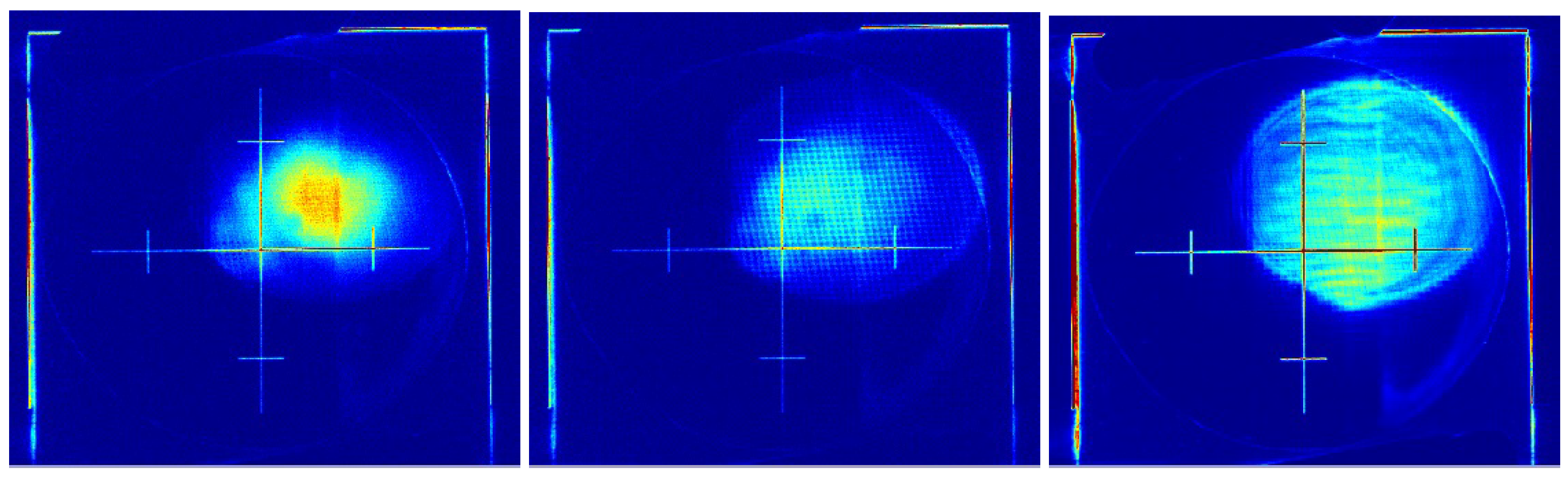
Figure 4 are from simulations as mentioned. However, the effect of the automatic optics adjustment can be clearly seen experimentally, as shown in
Figure 5, for the same beam energy of 380 MeV as in the simulations. The figure shows the photon beam on a YAG (Yttrium aluminium garnet)-screen for different wavelengths from 50 to 150 nm in a single scan, with automatic optics adjustment switched on, but no other parameters touched during this scan (The interference pattern visible on the screen is caused by a mesh, which is inserted in the photon beam upstream of one of the photon detectors. Furthermore, the YAG screen already shows some beam-induced damage, which makes the beam quality seem poorer than it actually is). In contrast, without adjusting the optics, the spot would look identical at
= 50 nm, where the undulator focusing is not yet important, but at
= 85 nm, the beam would have already become extremely large and the radiation power would have dropped. For wavelengths longer than
= 85 nm, the beam losses in the undulator would have exceeded the alarm threshold of the machine protection system and as a result, the beam would have been switched off. Including adjusted optics, one can continue to close the gaps down to 9 mm, corresponding to
= 150 nm without any problem. It is also clear from
Figure 5 that further improvement is still needed. Because no beam-based alignment was performed prior to this experiment, a small movement of the center of the beam is visible.
However, even given the need for further beam optics automation, first user experiments where the photon energy has been scanned across a resonance within minutes have already demonstrated the great advantages of tunable undulators for experiments at FLASH.
3. New Operation Modes
The variable gap undulators not only allow fast wavelength scans but also enable novel operation modes, such as advanced tapering schemes, frequency doubling, two-color operation, and harmonic lasing self-seeding. With optimized undulator tapering, photon pulse energies up to 1 mJ have been demonstrated at FLASH2 [
8]. A particularly interesting option in this respect is reverse tapering [
9,
10]. In combination with a harmonic afterburner for circular polarization currently under design this should in the future allow experiments with variable polarization at photon energies beyond the water window at FLASH2. Tuning the FLASH2 undulators individually it is also possible to push the photon energy range of FLASH beyond the current limit of 300 eV in the fundamental.
Setting the first part of the undulator section to twice the final wavelength in a frequency doubling scheme it has been shown that the photon energy range of FLASH2 can be extended up to 400 eV with stable pulse energies of a few
J, significantly higher than what has been achieved when the full undulator section is set to the final wavelength at the same electron energy [
11]. Another interesting option is harmonic lasing self-seeding (HLSS) which had been proposed a while ago [
12] as a method to reach higher photon energies with increased brightness. With FLASH2, HLSS was recently demonstrated for the first time experimentally and the theoretical predictions were confirmed [
13]. In the following some results for the different schemes will be presented.
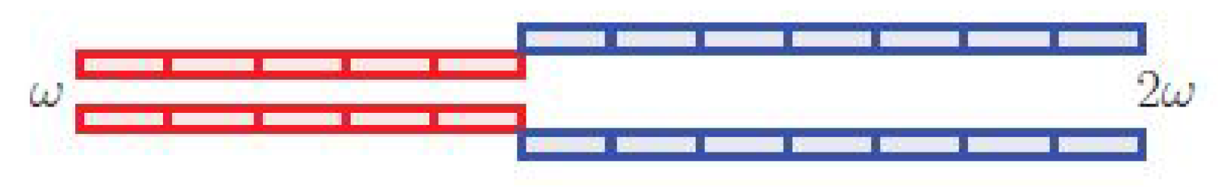
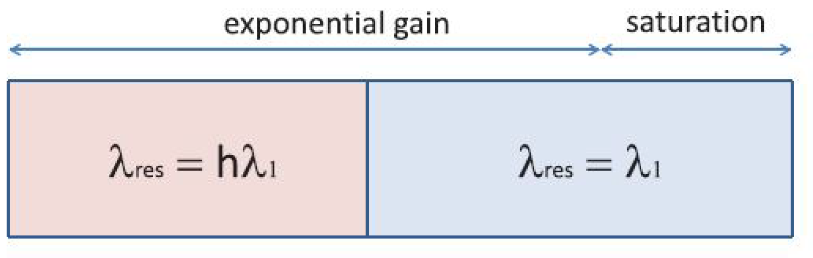
Harmonic lasing self-seeding (HLSS), while proposed some time ago, could never be tested at FLASH1 with its fixed gap undulators. HLSS requires the setting of the first part of the undulator section to a sub-harmonic (
) of the final wavelength which is schematically shown in
Figure 6. As can be seen in
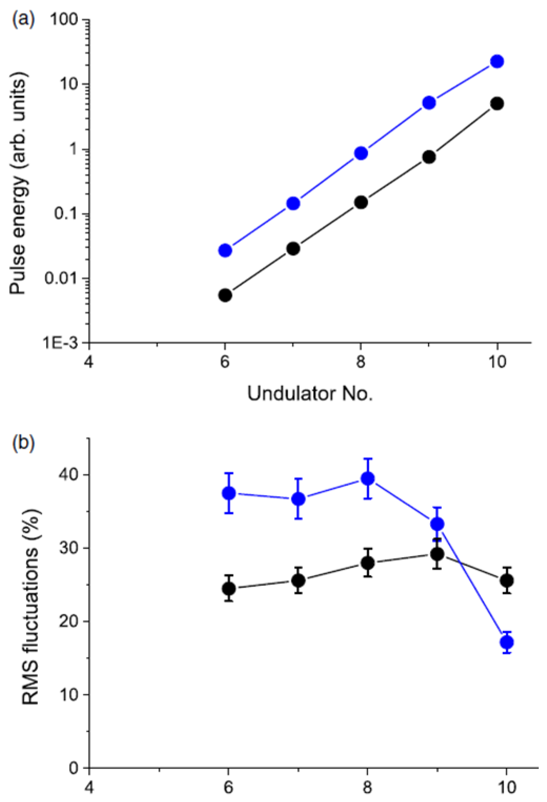
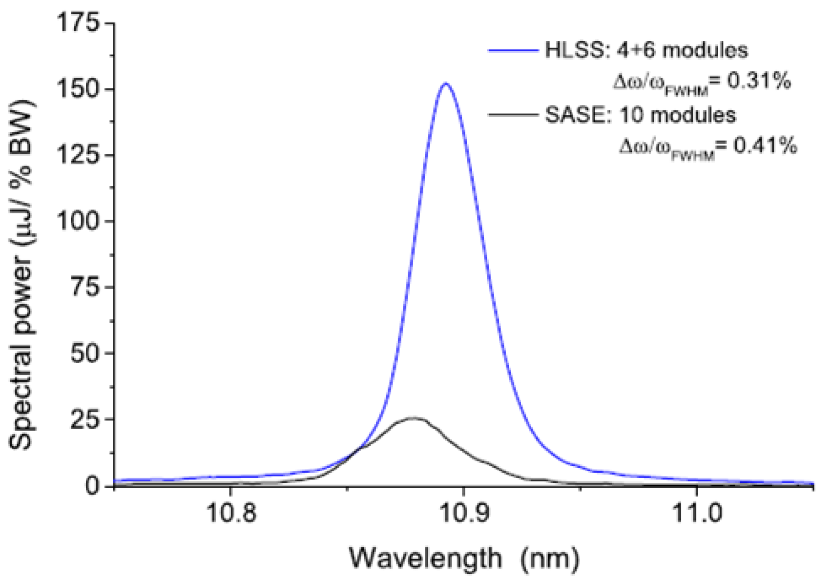
Figure 7, saturation is reached earlier with HLSS than with conventional SASE. This is clear from the higher power and the reduction in fluctuations when saturation is reached. More importantly, the bandwidth is also reduced and therefore the brightness is higher, as shown in
Figure 8. Due to the limitations of FLASH2, which was originally not built with this concept in mind, one can only go to the second or third harmonic of the wavelength selected for the first part of the undulator, but in principle, higher harmonics could be considered when an FEL line is specifically designed for efficient use of the HLSS scheme.
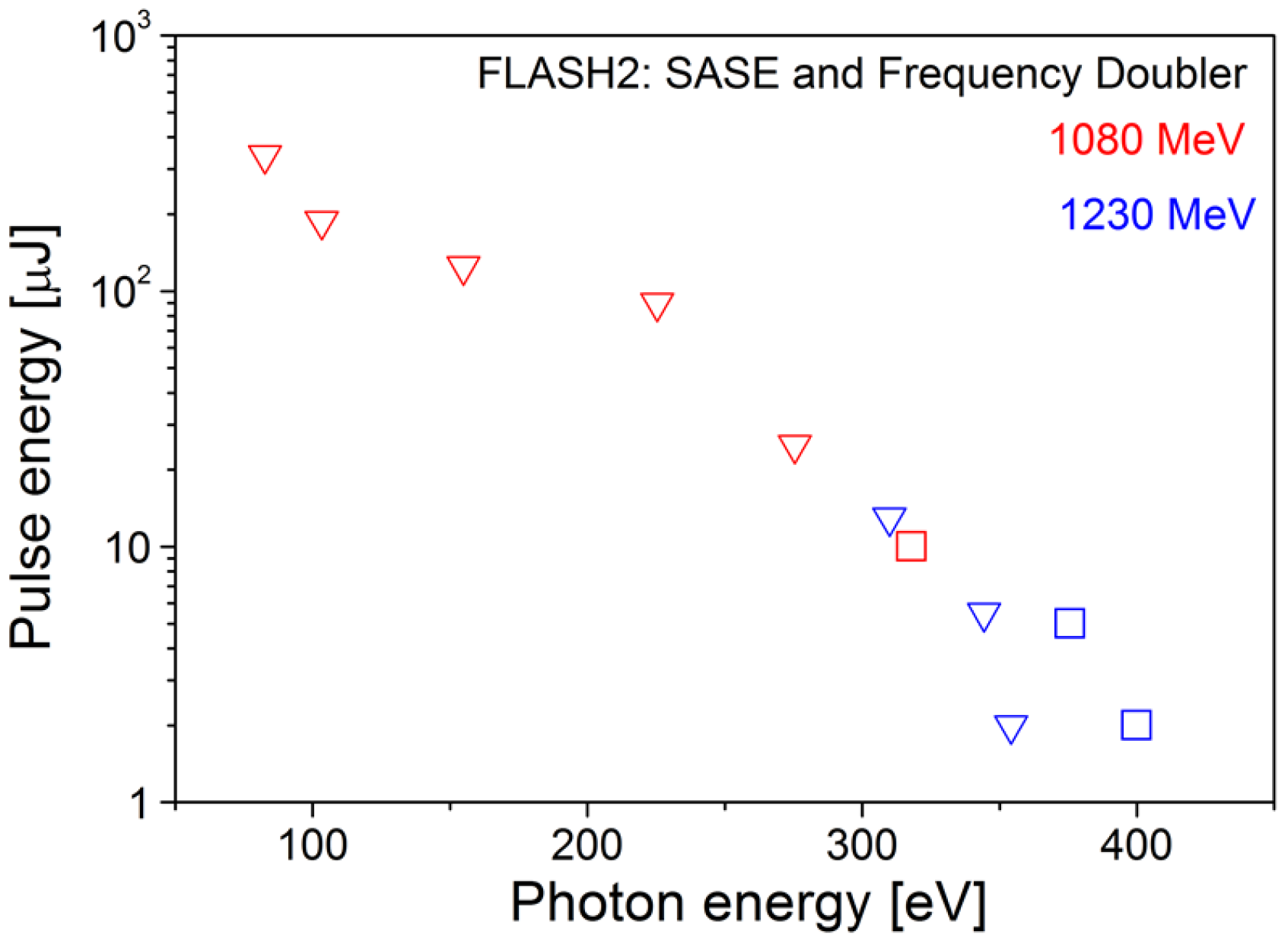
The wavelength limits can be pushed at FLASH2 by tuning the undulator sections individually as shown in the frequency doubler scheme in
Figure 9. Given the maximum electron beam energy of FLASH of 1.25 GeV, radiation in the water window at 4 nm can only be reached with the present FLASH2 undulator design and normal SASE operation with all undulators set to the same wavelength using the complete undulator length. Going to shorter wavelengths, the SASE intensity drops fast, because saturation is no longer reached. In addition, the SASE fluctuations increase for the same reason. Compared to this, the radiation intensity is clearly higher than it would be without a frequency doubler scheme, as can be seen in
Figure 10. In the experiment, first the fundamental at frequency
is tuned for maximum SASE gain in the uniform undulator. Analysis of the gain curve and fluctuations of the radiation pulse energy allows for determination of the optimum length of the
-section. Then, the remaining sections are tuned to the frequency
, and after adjustment of the phase shifters and electron beam orbit, the frequency doubler starts to generate radiation at the second harmonic.
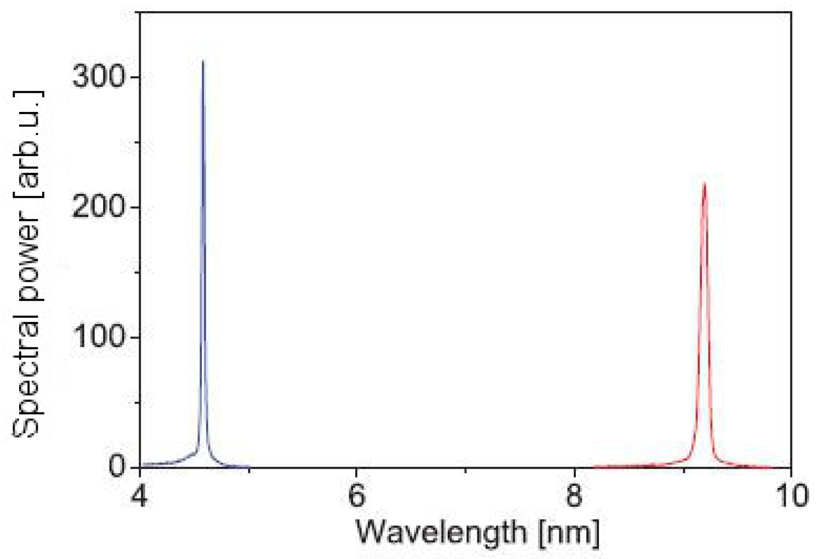
The same scheme can also be used for two-color operation of the FEL line. In
Figure 11 the spectral power obtained is shown for specific settings of the two undulator sections. The experiments show that two-color operation is possible with similar pulse energies of roughly 10
J. Moreover, the relative pulse energies of the two colors (
vs.
) can be tuned in wide limits.
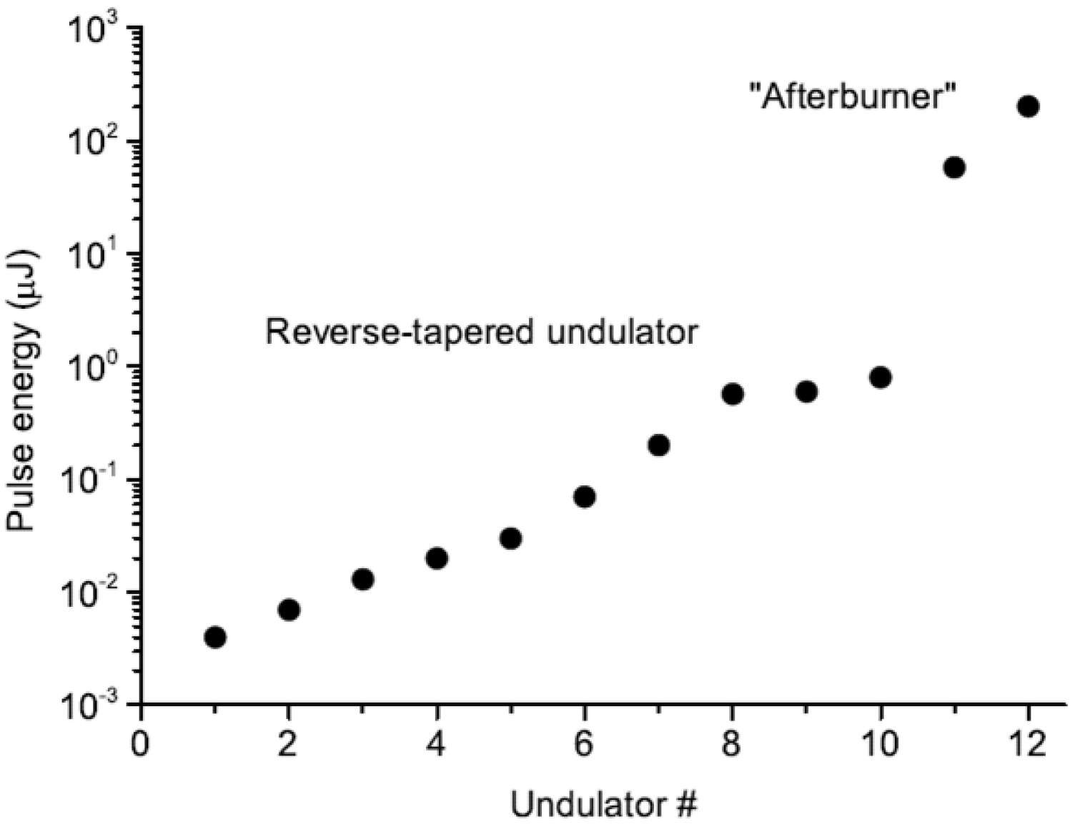
For an extreme case of frequency multiplication, using a short afterburner at for example the third harmonic, the power output is rather small because of the large energy spread generated in the main undulator section. In addition, if the afterburner generates circular polarized light at either the fundamental or odd harmonic, there is the problem that the linearly polarized light from the main undulator section produces a radiation pulse with roughly the same intensity. A proposal to improve this situation is found in [
9]. In this scheme, the radiation of the main undulator is suppressed by using an inverse taper. This scheme keeps the bunching to a large extent, but suppresses the radiation and therefore also the energy spread induced during the amplification process. The first experimental demonstration is given in [
10]. In the experiment shown in
Figure 12, the first 10 undulators of FLASH2 were set up with reversed taper, whereas the last two undulators where used as an afterburner, showing that even though the first 10 undulators did not produce a high radiation intensity, they did produce bunching. In this demonstration experiment, the last two undulators were set to the same wavelength, resulting in an increase in pulse energy exceeding two orders of magnitude.
4. Future Upgrades
The experimental hall of FLASH2 can accommodate up to six beamlines and experimental stations. Since spring 2016, the beamlines FL24 and FL26 have been open for users. FL24 provides an open port for user-supplied experiments and has been equipped with KB (Kirkpatrick-Baez) focusing optics with bendable mirrors in order to adapt focus size and focal length to user demands. At FL26, the permanent end station REMI, a reaction microscope from the Max-Planck Institute for Nuclear Physics in Heidelberg, has been installed for advanced AMO (atomic, molecular, and optical) physics and molecular femtochemistry experiments [
15]. As one of the next beamlines, a new time-compensating monochromator will be installed in the FLASH2 experimental hall. The design for this beamline has recently been finalized after intense discussions with the user community. In addition, it is planned to install a THz undulator at FLASH2 and to integrate a THz streaking station based on a single cycle source in the FLASH2 photon diagnostics section for online pulse duration monitoring.
The FLASH2 FEL control system is not yet completely finished. Regarding the control system, the undulator server, which controls the undulator gaps, phase shifters, and aircoils to correct gap-dependent kicks, now includes the automatic focusing. This means that with one click, one can change the wavelength, keeping the phases, undulator gaps, and focusing at an optimum. However, the undulator length and the starting point for and degree of tapering will also be determined in the near future automatically [
16].
The new opportunities with the variable gap undulators in the FLASH2 line outlined above will significantly enhance the FLASH performance for users in the coming years. In the period from 2018 to 2020 we plan to refurbish two accelerator modules in the linac and to install a variable polarization afterburner in FLASH2. Furthermore, a new flexible injector laser for FLASH will be developed which can provide flexible electron bunch patterns at the full repetition rate for simultaneous operation of FLASH1 and FLASH2. In FLASH2, an X-band-deflecting cavity will be installed behind the undulators for advanced diagnostics of SASE pulses. The electron beam diagnostics will be upgraded with particular emphasis on low-charge operation required for the shortest SASE pulses. DESY is also currently in a preparation phase for a long-term upgrade plan of FLASH known as “FLASH2020”. A major part of FLASH2020 will be the exchange of the fixed gap undulators in FLASH1 and the implementation of a new flexible undulator scheme aimed at providing coherent radiation for multi-color experiments over a broad wavelength range.


 ,
, 


