Study on the Hydrodynamic Performance of Typical Underwater Bionic Foils with Spanwise Flexibility


1
College of Mechanical and Electronic Engineering, Shandong Agricultural University, Taian 271018, China
2
State Key Laboratory of Robotics and System, Harbin Institute of Technology, Harbin 150001, China
*
Author to whom correspondence should be addressed.
Appl. Sci. 2017, 7(11), 1120; https://doi.org/10.3390/app7111120
Submission received: 22 September 2017
/
Revised: 25 October 2017
/
Accepted: 26 October 2017
/
Published: 30 October 2017
(This article belongs to the Section Mechanical Engineering)
Abstract
:Bionic foils are usually similar in shape to the locomotive organs of animals living in fluid media, which is helpful in the analysis of the motion mode and hydrodynamic mechanisms of biological prototypes. With the design of underwater vehicles as the research background, bionic foils are adopted as research objects in this paper. A geometric model and a motion model are established depending on the biological prototype. In the model, two typical bionic foils—a NACA foil and a crescent-shaped foil—are chosen as research objects. Simulations of the bionic foils are performed using a numerical method based on computational fluid dynamics software. The hydrodynamic forces acting on the foils and flow field characteristics behind the foils are used to analyze the propulsion performance and hydrodynamic mechanism. Furthermore, a spanwise flexibility model is introduced into the motion model. Next, the hydrodynamic mechanism is further analyzed on the basis of hydrodynamic forces and flow field characteristics with different spanwise flexibility parameters. Finally, an experimental verification platform is designed and built to verify the reliability of the numerical results. Agreement between the experimental and numerical results indicates that the numerical results are reliable and that the analysis of the paper is reasonable.
1. Introduction
In nature, through natural selection over thousands of years, creatures have developed the ability to swim or fly in fluid media such as air or water. In contrast, the propulsion performance of conventional screw propellers, which are widely used, is poor in comparison with that of animals. Therefore, a study of the propulsion modes of swimming or flying creatures has important significance to underwater propulsion. In the mechanical discipline, biomimetics has become a research focus [1]. Moreover, biomimetics is of vital importance in underwater exploration, ocean exploitation, national security and other important domains. Through technological advancement, different bionic propulsors have been successfully developed [2,3,4]. Unfortunately, the propulsion performance of these bionic propulsors cannot match that of their biological prototypes, which highlights the necessity of further study of propulsion mechanisms. The mechanism research plays an important role and will boost the development of the principle prototype. To reveal the mechanism of high-efficiency propulsion, scholars at home and abroad have devoted considerable effort with different research methods [5,6,7]. However, both the prototype-based experimental results and the numerical results achieved are far from the expected performance. Taking the high-efficiency propulsor developments as the research background, this paper chooses typical foils as the research objects and focuses on the propulsion mechanism of bionic foils.
In decades past, computer technology has developed immensely. Accordingly, numerical simulation based on computational fluid dynamics (CFD) has been widely used in studies of biological propulsion. New numerical methods were proposed during the past two decades and the calculation precision has been improving [8]. Compared with other methods, the flow field characteristics and hydrodynamic forces at any time can be easily extracted. Such flow field characteristics are important in the analysis of hydrodynamic mechanism. Furthermore, the numerical simulations require less time and can be easily conducted. Therefore, the CFD method is widely adopted to solve the Navier-Stokes equations, which has become an important method in the visual simulation of fluids. However, in biofluid dynamics research, fluid-structure interaction (FSI) problems are universal [9,10,11]. For this kind of problem, interactions exist among the viscous fluid, deformable body and free-moving boundary [12,13,14]. Therefore, these problems are difficult to solve.
The previous studies of underwater biological propulsion usually focused on the locomotion of biological prototypes [15,16]. And biological observation was usually used in these studies. These biological prototypes, like tunas, usually use the common “body/caudal fin” swimming mode and have advantages of high propulsive efficiency and high speed. In these studies, detailed flow field characteristics or hydrodynamic forcescannot be provided. Through technological advancement, numerical simulation of underwater biological propulsion was conducted by scholars. Different biological prototypes were studied as research subjects. The detailed flow field characteristics and hydrodynamic forces can be provided with numerical simulations. For example, Borazjani and Sotiropoulos carried out fluid-structure interaction simulations to investigate the hydrodynamic mechanism in carangiform swimming [15,16]. However, the experimental method is still necessary because of the accuracy of numerical calculation. Besides that, the numerical simulation of self-propulsion is usually difficult to conduct. So, the swimming velocity of biological prototypes was usually set as a constant in previous numerical studies [17,18]. To simplify the problem of biological propulsion, the wings or fins of animals living in fluid media can be abstracted to bionic foils [19,20,21,22]. Study of the hydrodynamic mechanism of bionic foils would help to reveal the hydrodynamic mechanism of biological prototypes [23,24,25]. Additionally, bionic foils can easily be applied to the existing underwater propellers. Related research has been conducted aiming at the problem. However, the foils were usually modeled in two dimensions or simplified to simple three-dimensional shapes [26,27,28]. Li et al. mainly studied the wake topology of forked and unforked fish-like plate with numerical method [10]. Izraelevitz et al. studied experimentally the effect of adding an in-line oscillatory motion to the oscillatory heaving and pitching motion of flapping foils that use a power down stroke [19]. In addition, the foils in previous studies were usually regarded as rigid bodies. As is widely known, the locomotive organs of animals are flexible. The flexibility would influence the propulsion performance. Especially, spanwise flexibility merits more attention and further study because of the high aspect ratio of the bionic foil. As is shown in [29], a water tunnel study of the effect of spanwise flexibility on the thrust, lift and propulsive efficiency of a rectangular foil oscillating in pure heave was performed. Zhu et al. numerically examined the performance of a thin foil reinforced by embedded rays resembling the caudal fins of fish [30]. The numerical studies of spanwise flexibility on complex shaped foils were few. In [31], the influences of the motion parameters on the propulsion performance of a bionic caudal fin were analyzed by extracting performance parameters. In this paper, a more in-depth analysis is conducted aiming to further reveal the influences of spanwise flexibility by extracting the vortex patterns in the wake.
To investigate the propulsion mechanism of bionic foils, this paper establishes a numerical model of propulsion of bionic foils and proposes a corresponding numerical method. First, according to the biological observations, a geometric model and a kinematics model of bionic foils are established. Next, the proposed numerical method is used to accomplish numerical simulations and study the propulsion mechanism of a NACA foil and a crescent-shaped foil. Additionally, a self-propulsion model of a thunniform bio-inspired model is adopted to verify the numerical model and solution approach and to further analyze the hydrodynamic mechanism of the thunniform mode. After that, the effects of spanwise flexibility on the propulsion performance are studied. By extracting the flow field characteristics in the wake and hydrodynamic forces acting on the foil, the hydrodynamics mechanism of these effects is analyzed. To verify the reliability of the numerical results, verification experiments are conducted.
2. Materials and Methods
2.1. Geometric Model
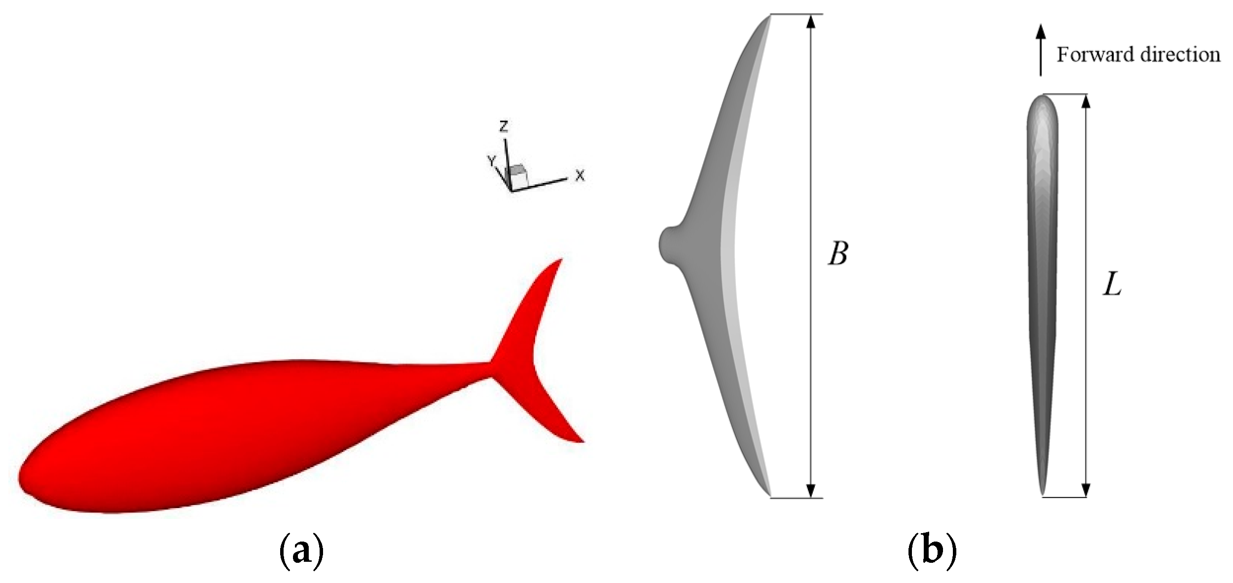
The thunniform mode features high efficiency and high speed. Many fish species that have a singular ability to swim adopt this mode, such as sharks, swordfish and tuna. The fish species utilizing the thunniform mode mainly generate thrust force by swinging their caudal fins. Specifically, the caudal fins achieve thrust force through a motion that contains translational motion following the tail and rotation motion around the tail. Except for the motion of the caudal fin, the motion of the fish body exists mainly in the rear part and front part of the fish body is relatively rigid. Moreover, a crescent-shaped caudal fin is the most common shape among thunniform swimmers. For example, a crescent-shaped caudal fin can provide ninety percent of the thrust force for a tuna, meanwhile pectoral and pelvic fins play roles only in controlling the attitude. A crescent-shaped caudal fin with a high aspect ratio is conducive to the shedding of the vortex rings, which in turn reduces the energy consumption during the shedding process and achieves high propulsive efficiency. In this section, as shown in Figure 1, three-dimensional geometric models are established with the thunniform group as the bionic prototype. Fins that work as auxiliary organs, such as pectoral and pelvic fins, are not taken into account. The geometric model contains three parts: head, trunk and caudal fin. The lengths of these three parts are 0.28 m, 0.4 m and 0.12 m, respectively.
The cross-sectional shape of the geometric model is shown in Figure 2 and the curve equations are defined as follows:
In the process of geometric modeling, the section shape perpendicular to incoming flow is defined as elliptical surface. In the process of geometric modeling of the crescent-shaped foil, firstly z3 function and y3 function in Equations (1) and (2) are used to construct the incomplete three-dimensional geometry of the foil, after that a curved surface defined by z4 function in Equation (1) is used to cut the geometric model. Finally, the three-dimensional geometric model of the crescent foil which is similar as the caudal fin of thunniform mode is completed.
In nature, locomotive organs with different shapes exist in the animal kingdom. In particular, the animals that swim or fly in fluid media usually have locomotive organs with similar cross sections along the flow direction. The force acting on locomotive organs can be regarded as the resultant force of force components acting on cross sections. Here, a flapping foil model is adopted to represent the general form of these locomotive organs. The cross sections of the bionic foils adopted in this paper have same shape as the NACA (National Advisory Committee for Aeronautics) airfoil model. As shown in Figure 3, the NACA0013 airfoil is chosen as the cross section, where L is the chord length, B is the length along the spanwise direction and O is the reference point. The reference point is set a quarter of the chordwise length away from leading edge.
With this NACA foil as the research object, the results of the study would contribute to revealing the mechanism of biological propulsion. In addition, a propulsion system with a NACA foil can fully absorb the advantages of different bionic prototypes and can be applied to existing propulsion systems.
2.2. Motion Model
For the thunniform bio-inspired model, the motion contains swinging of the caudal fin and waving of the body. Based on the geometric model, the waving of the body is abstracted to a traveling wave that transfers from head to tail of the body with gradually increased amplitude. The traveling wave can be written as:
where y is the displacement along the y direction, A is the amplitude, k is the wave number, f is the frequency and x is the x coordinate. The wave number can be given as:
where λ is the wavelength of the traveling wave of the body. The amplitude A contains two parts and the location term a1 and time term a2 can be written as:
where Lf is the length of body, t0 is the startup time and the c terms with subscripts are the coefficients of the amplitude envelope. The time term a2 is used to accomplish a smooth start.
For the crescent-shaped caudal fin and the NACA foil to imitate the forward movement of the bionic prototype, the foil moves forward at a constant speed U. In addition, the foil undergoes heave motion y(t) and pitch motion θ(t) at the same time. The heave motion is translational motion transverse to the direction of propulsion and the pitch motion is angular motion around a spanwise axis. Except for the towing motion, the translational motion of the foil is expressed as:
Here, h is the amplitude of the heave motion. Additionally, the tangent angle of trajectory θm can be described as:
The angle α(t) is the angle of attack and can be written as:
where αmax is the amplitude. The definitions of relevant parameters are shown in Figure 4. The role of heave motion is to accomplish thrash motion and the role of pitch motion is to adjust the angle of thrash motion.
2.3. Flexibility Model
In nature, the locomotive organs of animals that swim or fly in fluid media are usually flexible. Therefore, flexibility should be modeled during the propulsion of locomotive organs in the study of propulsion of bionic foils. However, the modeling and solving of passive deformation are difficult. To simplify the problem, a defined flexible deformation model is imposed on the foil during the motion. In addition, the defined flexible deformation model can be easily applied to foil propulsion, to enhance the propulsion performance of the system. Because of the high aspect ratio of the bionic foil, spanwise flexibility merits increased attention and further study. In the spanwise flexibility model, a phase difference γ is introduced into the definition of α(t). Bases on Equation (9), the angle of attack on the edges is rewritten as:
The angles of attack of the center points are still calculated according to Equation (9). This definition leads to a phase difference between the pitch motion of the center points and the edge points at the same chordwise position. The shape description of the flexible NACA foil is shown in Figure 5. With different mathematical curve forms, the coordinates of points at the edge and center locations can be used to construct a curve equation and using this curve function, the coordinates of other points at the same chordwise position can be calculated. Figure 6 shows the shape of the crescent-shaped foil with a typical phase difference. Specifically, the thrash surface is convex when the phase difference is positive. Conversely, the thrash surface is concave when the phase difference is negative.
2.4. Numerical Solution
The URANS (Unsteady Reynolds Averaged Navier Stokes) model is adopted in the numerical simulations. Using this model, the Navier-Stokes equations used to describe the hydrodynamics of fluids are restructured as:
where ρ is the density, ν is the kinematic viscosity and p is the pressure. The subscript i and j represent the three coordinate directions. Here, the dependent variables are not only a function of the space coordinates but also a function of time. Therefore, the simulated velocity in URANS model can be split to the time-averaged part U and the fluctuations u. To close the equations, the Reynolds stresses term, the last term in Equation (11), can be expressed with the mean velocity gradient via the eddy viscosity. The eddy viscosity can be represented by k (turbulent kinetic energy) and ε (the velocity and length scale of turbulent motion), that is the k-ε turbulence model. The numerical simulations are carried out by Fluent (ANSYS Inc., Canonsburg, PA, USA) software. The Finite Volume Method (FVM) is adopted to discretize the Navier-Stokes equations into expressions that are first-order in time and second-order in space. The tetrahedral grid is used to divide the computational domain. The simulation is a dynamic process and the boundaries of the foil are changing constantly. The dynamic mesh method reconstructs the mesh at each time step and User-Defined Functions (UDF) linked to Fluent define the motion of the moving boundaries. For a single crescent-shaped foil separated from the fish body or NACA foil, the simulations are started from the static state and then the foil is towed forward and moves according to the motion model defined above. For the thunniform bio-inspired model, the self-propulsion model is adopted. In other words, the thunniform bio-inspired model attempts to generate thrust by swinging the caudal fins and waving the body. As a result, the hydrodynamic forces acting on the body and caudal fin achieve forward propulsion of the thunniform bio-inspired model. At each time step, the hydrodynamic forces are extracted and then the position and attitude of the thunniform bio-inspired model are calculated according to the hydrodynamic forces. Without taking into account the flexibility, the bionic foils can be treated as rigid bodies. In these cases, the translational and rotational motion of the bionic foils can be defined by DEFINE_CG_MOTION function. In addition, DEFINE_GRID_MOTION function is adopted to define the motion of the flexible foils and thunniform bio-inspired model. Using this function, the deformation velocity of each grid point can be defined in each time step.
During the calculation, the SIMPLE algorithm of the pressure-speed amending method is adopted and the k-ε turbulence model is adopted. To ensure the accuracy of the calculations, the maximum number of iteration steps is 50 and every motion period contains 200 time steps. The wall boundary condition is set at the solid boundaries and symmetry boundary conditions are imposed on the boundaries of the fluid domain. To exclude the influence of the wall effect, the computational domain is set sufficiently large. To verify the grid independency, choosing thrust velocity as the assessment index, three numerical simulations with different grid size are carried out and GCI (grid convergence index) was calculated. It is found that the grid size adopted in the paper can meet both the precision requirement and computational efficiency requirement. Besides that, the simulation with a 50% time step is carried out and only 6% of the difference between the big time step and the small time step is found. Similar verification processes are conducted before numerical simulations of bionic foils. For example, the computational domain and grids of the thunniform bio-inspired model are shown in Figure 7. The domains of bionic foils are discretized into about 8.0 × 10⁵ grid cells and the domain of thunniform bio-inspired model is discretized into about 6.0 × 10⁶ grid cells. Additionally, a refined mesh is adopted near the boundaries of the solid domain. To avoid repetition, the computational domain and mesh generation of the bionic foils are not described here.
Relevant kinetic parameters should be calculated. For bionic foils, the chord Reynolds number and Strouhal number are defined by
where ν is the fluid kinematic viscosity. The Strouhal number is an important parameter in biological swimming models. Many fishes can maintain high propulsion performance when the value of the Strouhal number is approximately 0.3. In addition, a dimensionless method of forces and torque is used [19] and the method can be written as:
Here, Fy is the transverse force, Fx is the thrust force, Mθ is the torque and S is the projected area of the foil. As shown in [19], the propulsive efficiency η can be written as:
where Po is the output power, Pe is the input power and T is the period of the motion.
3. Results and Discussion
3.1. Rigid Foil
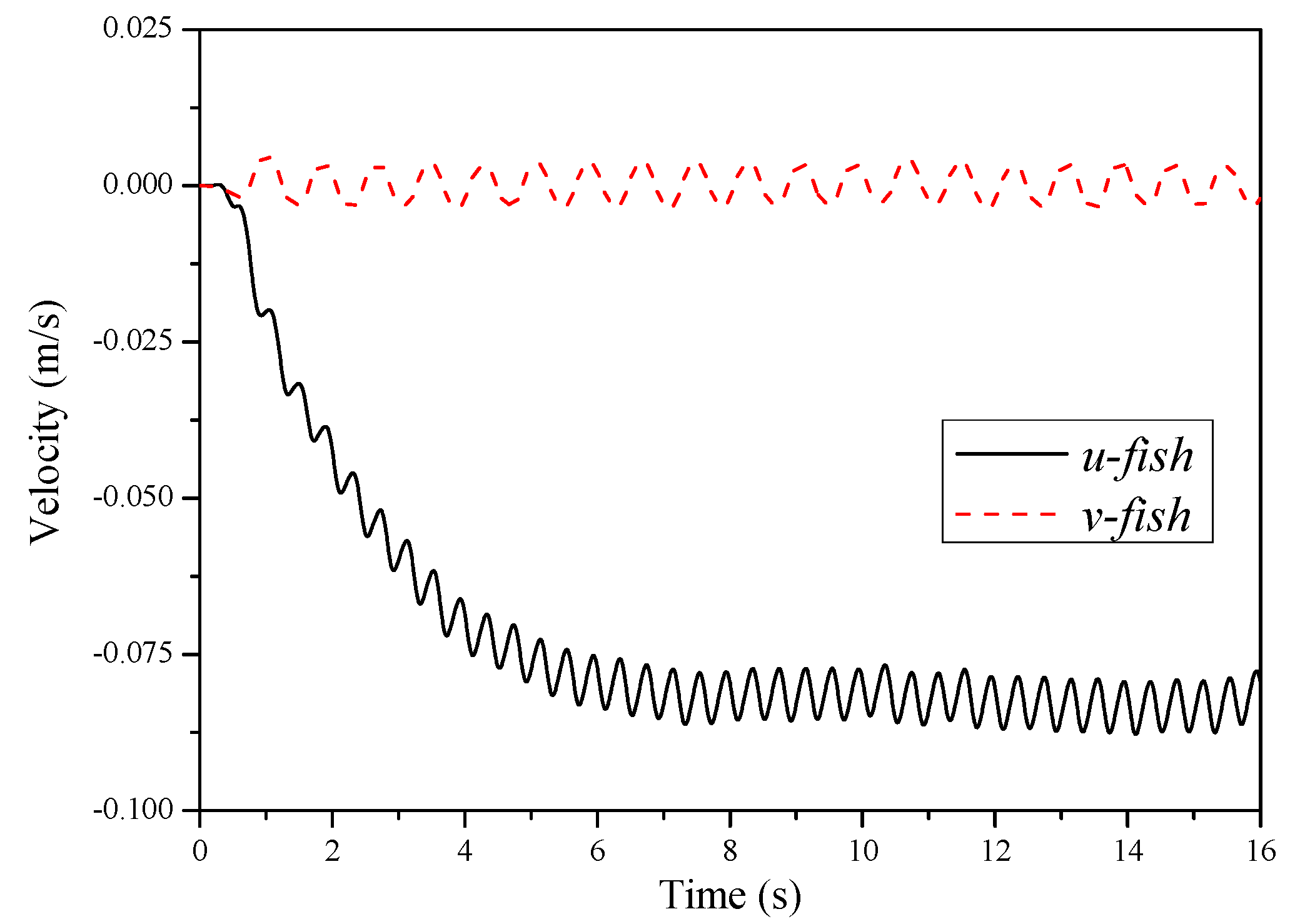
The geometric parameters and motion parameters of the thunniform bio-inspired model are assigned as follows: Lf = 0.16 m, λ = 1.0Lf, αmax = 20°, h = 0.5L and f = 1.25 Hz. Here, Lf is the length of the thunniform bio-inspired model and L is the chord length of the caudal fin. The thunniform bio-inspired model moves from the static state. Figure 8 shows the velocity time-histories of the thunniform bio-inspired model. Here, u-fish is the velocity along the propulsion direction and v-fish is the velocity transverse to the propulsion direction. Initially, u-fish is zero and then increases gradually, until it finally reaches dynamic stability. Furthermore, u-fish and v-fish are not constant, but oscillate around a constant value. The process for reaching dynamic force balance is gradual.
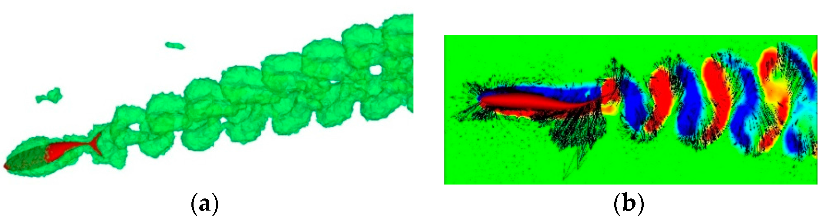
Figure 9 shows the vortex pattern in the wake. There are vortex rings behind the thunniform bio-inspired model. The vortex ring consists of a train of inverted hairpin-like vortices braided together such that the legs of each vortex are attached to the head of the preceding vortex. Specifically, Figure 9b shows the vorticity magnitude and velocity vector in two-dimensional space. The vortices shed from the thunniform bio-inspired model are arranged in two ranks in the wake, which can generate a jet stream. As a result, the thunniform bio-inspired model obtains a corresponding reaction force. The arrangement and shape of vortex pattern are similar with those found in nature and agree well with other research [15]. Hence, the numerical model and solution approach adopted in this paper are reliable.
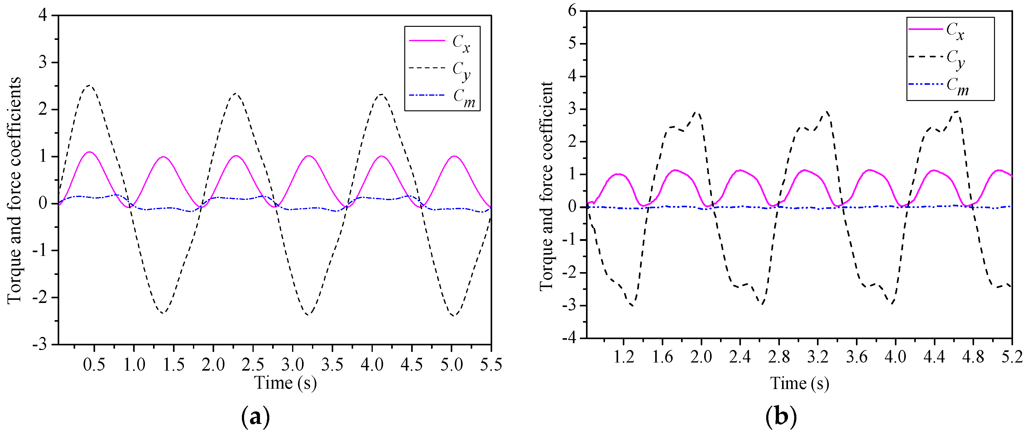
The geometric parameters and motion parameters of the NACA foil are assigned as follows: h = L = 0.055 m, B = 0.3575 m, αmax = 25°, St = 0.3 and Re = 11,000. As shown in Figure 10a, the forces and torque acting on the NACA foil fluctuate periodically. In one cycle time, the resultant force of the transverse force in a motion period is zero and the thrust force is positive. That is, the NACA foil can obtain forward thrust force and eliminate transverse force. To verify validity and feasibility of the method, the geometry parameters and motion parameters are set to be consistent with those of other experimental study [19]. Furthermore, the mean Cx is 0.58, the mean Cy is 0.0065 and the thrust efficiency is about 47.0%. Comparing with the experimental study, the curves of force coefficients have similar trends and the performance parameters compare well with it (Cx = 0.604, Cy = 0.0082, η = 49.1%). Moreover, the forces and torque curves of the crescent-shaped foil are shown in Figure 10b. The curves are similar to those of the NACA foil. Additionally, three-dimensional vortex patterns in the wake of the NACA foil and crescent-shaped foil are shown in Figure 11. The vortex pattern has similar arrangement and shape with that of thunniform bio-inspired model, which also compare well with other researches [32,33,34]. Continuous vortex rings can be found in the wake, but the vortex rings behind the crescent-shaped foil are more complex because of the more complex geometry. The geometric parameters and motion parameters of the crescent-shaped foil are assigned as follows: h = 0.06 m, L = 0.15 m, αmax = 25°, St = 0.3 and Re = 45,000.
3.2. Flexible Foil
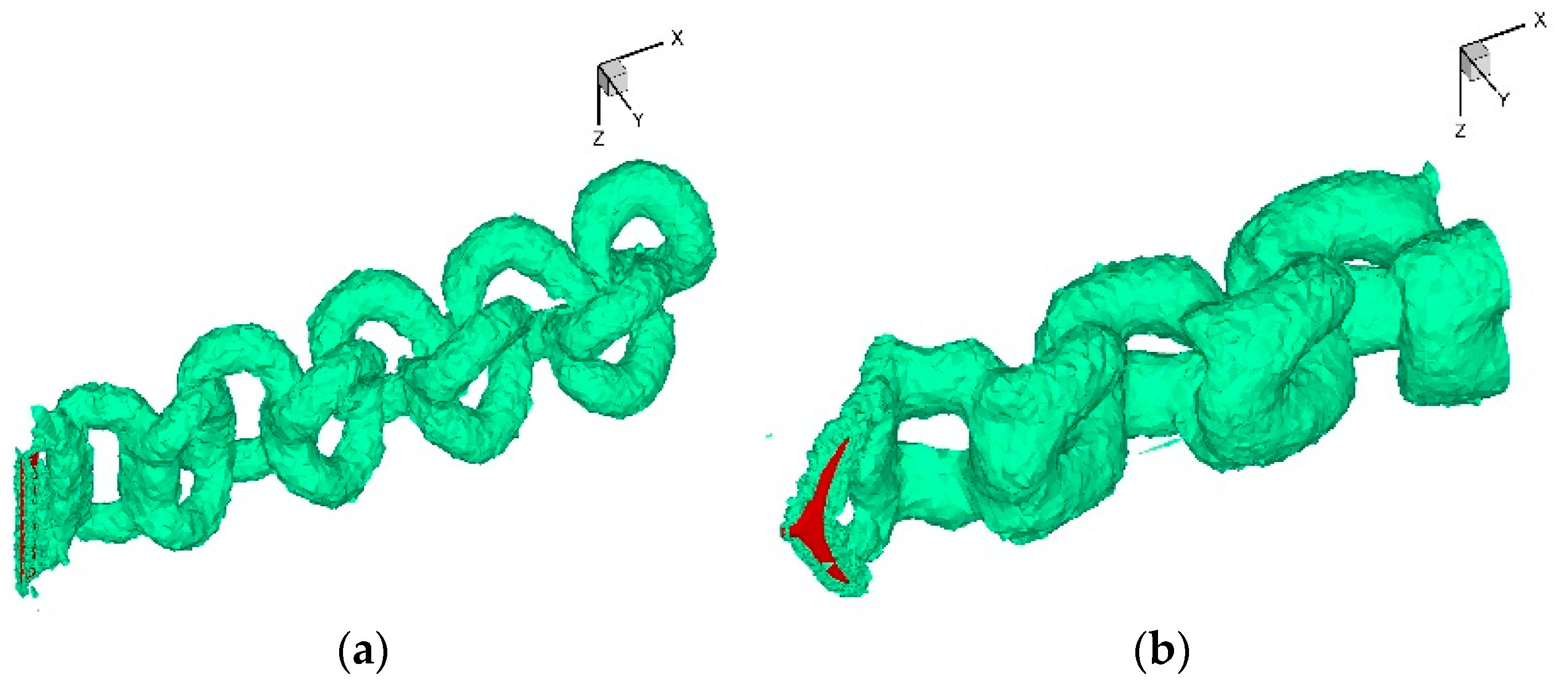
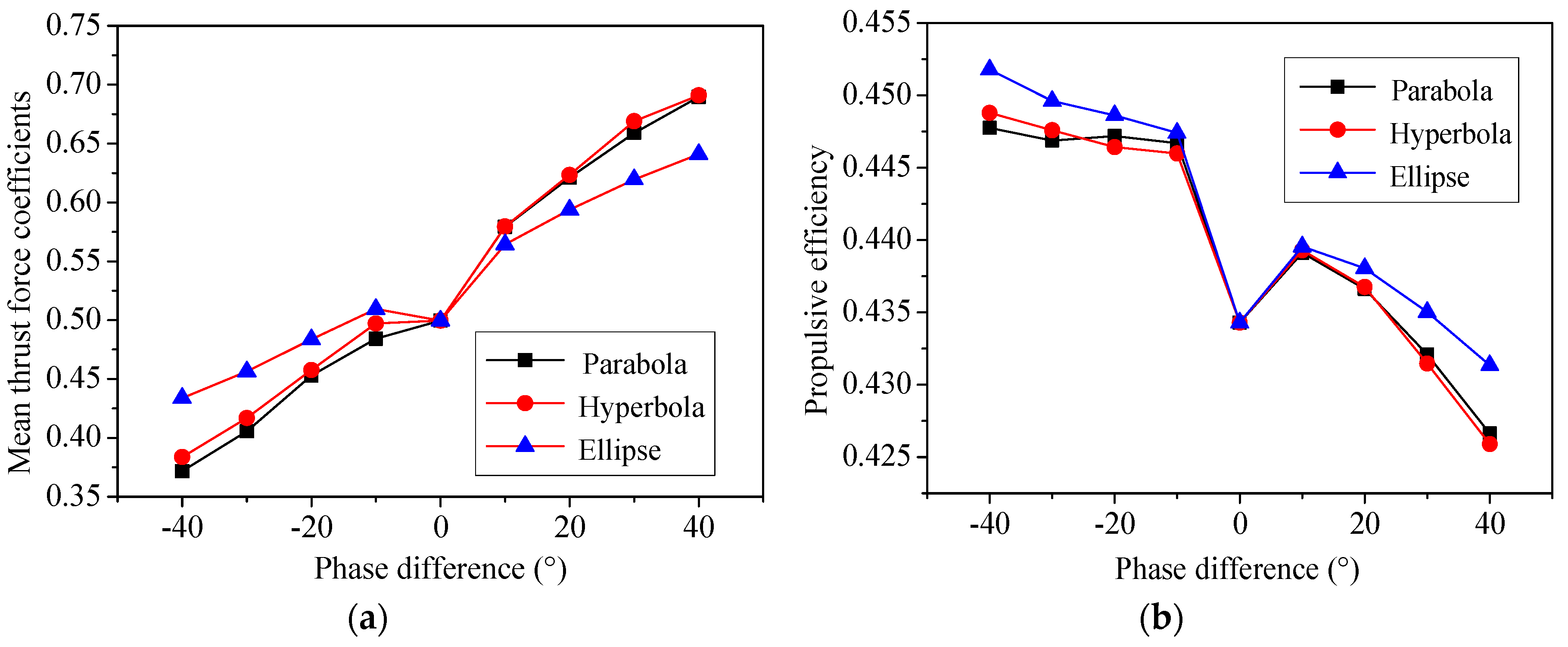
This section focuses on the influences of spanwise flexibility. Figure 12 shows the performance curves versus flexibility phase difference of the NACA foil. The case with γ = 0° stands for a rigid NACA foil. Additionally, an elliptic curve, a hyperbolic curve and a parabolic curve are used as curve functions respectively. The figure shows that spanwise flexibility can enhance the propulsive efficiency slightly within a certain range, but the mean thrust force coefficients can achieve higher values when the flexibility phase difference is positive. Moreover, the elliptic curve is more conducive to enhancement of the propulsive efficiency, but less conducive to enhancement of the mean thrust force when the phase difference is positive. And there is little difference between the performance of the hyperbolic curve and the parabolic curve. In addition, the NACA foil can achieve both higher mean thrust force and propulsive efficiency when the flexibility phase difference is between 10° and 20°. Figure 13 shows the three-dimensional vortex pattern in the wake of the NACA foil for typical flexibility phase differences for the elliptic curve. The figure shows that the vortex rings are stretched and the volume is larger when γ = 20° compared to γ = −20°. A stronger jet stream can be generated between the vortex ranks when γ = 20° and, in turn, the reaction force acting on the foil is enhanced accordingly. As a result, the propulsion performance is enhanced. This result indicates that spanwise flexibility can influence the shedding of vortex rings, further influence the arrangements of vortex rings and eventually lead to a change of propulsion performance. Furthermore, positive values of flexibility phase difference are more conducive to enhancing the propulsion performance than are negative values. The geometric parameters and motion parameters of the NACA foil are assigned as follows: h = 0.05 m, L = 0.1 m, B = 0.3 m, αmax = 25°, St = 0.3 and Re = 20000.
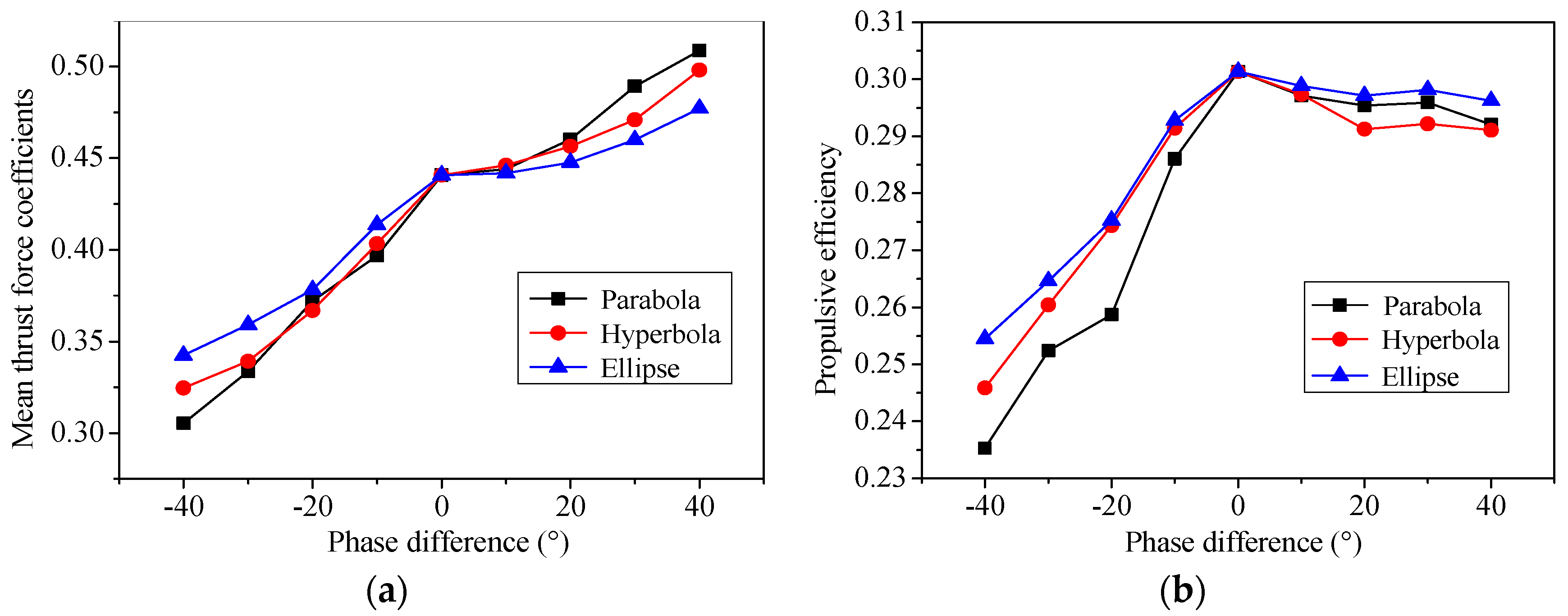
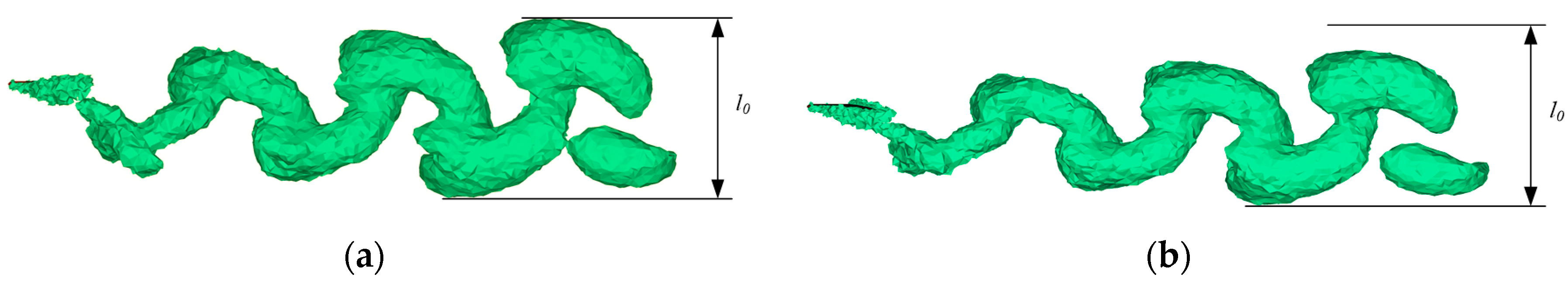
Figure 14 shows the performance curves versus flexibility phase difference of the crescent-shaped foil. The elliptic curve is more conducive to enhancing the propulsive efficiency, which is similar to the result for the NACA foil and the curves of the mean thrust force coefficients have similar trends as those of the NACA foil. In contrast, the crescent-shaped foil can maintain a relatively high propulsive efficiency value while achieving a larger mean thrust force within a relatively large range of flexibility phase difference. Natural caudal fins of fish usually have a shape similar to that of the model when the flexibility phase difference is positive. The results indicate that reasonable spanwise flexibility can enhance the propulsion performance of a crescent-shaped foil significantly. As shown in Figure 15, the vortex rings in the wake of the crescent-shaped foil under typical flexibility phase differences have forms similar to those of the NACA foil, so further analysis is not described here. The geometric parameters and motion parameters of the crescent-shaped foil are assigned as follows: h = 0.06 m, L = 0.15 m, αmax = 25°, St = 0.3 and Re = 45,000.
4. Experiments and Discussion
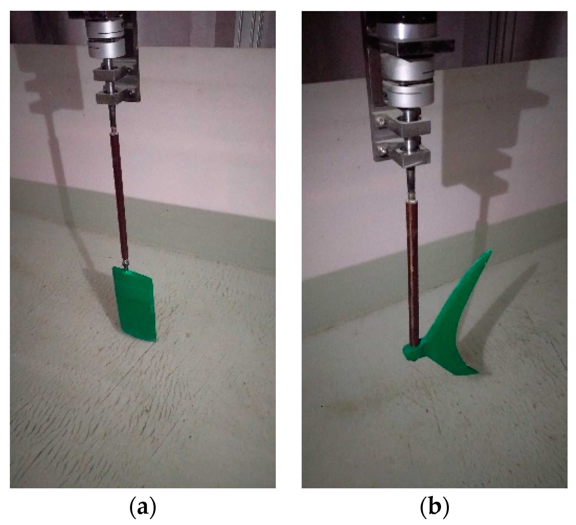
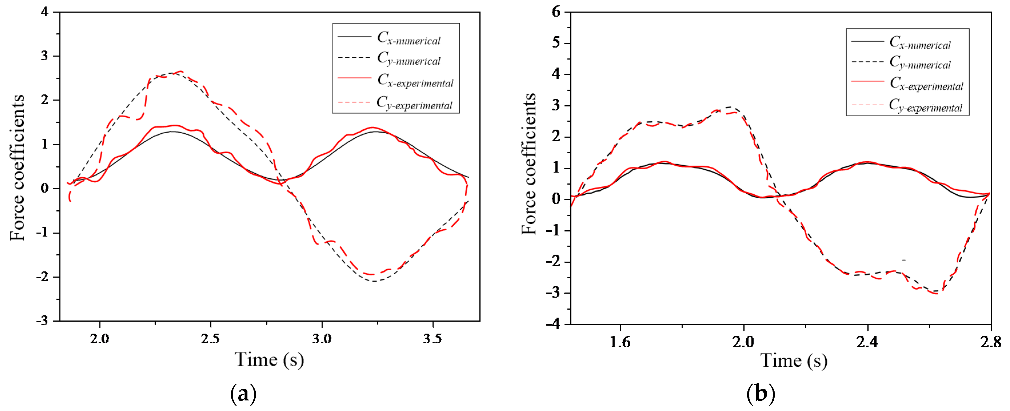
To verify the reliability of the numerical results, an experimental verification platform is designed and built. The bionic foil can be driven by three servo motors and hydrodynamic forces are measured through a force sensor. The servo motors are controlled through an upper computer and a motion control card. Under this reasonable control method, the bionic foil can move according to the preset motion model. Figure 16 shows installation photos of the bionic foils. The bionic foils are placed in the center of the water tank. The median filter algorithm is adopted in the data processing of the original data. Figure 17 shows the experimental results and numerical results of the NACA foil and the crescent-shaped foil. The geometric parameters and motion parameters chosen in this section are consistent with parameters defined in numerical simulations of rigid foils. The sampling frequency of the force sensor is set to 50 Hz and the bionic foils are colored green to make them readily observable. The hydrodynamic forces are chosen as the assessment index. It can be seen that the overall trends of hydrodynamic forces are consistent between numerical results and experimental results. Because of instrumental error, there are small-scale oscillations in the experimental curve. It indicates that the numerical method can correctly describe the change process of hydrodynamic forces acting on the bionic foils.
The mean thrust force coefficient of the NACA foil measured by experiment is approximately 0.58, which is close to the numerical result (0.60). Similarly, the mean thrust force coefficient of the crescent-shaped foil measured by experiment is approximately 0.44, which compares well with the numerical result (0.47). It can be seen that the experimental results compare well with the numerical results under certain parameter settings. It indicates that the numerical method adopted in the paper is reliable under similar parameter settings. Therefore, the numerical results in the paper are reasonable and the analysis would provide theoretical reference for revealing the hydrodynamic mechanism.
5. Conclusions
In this paper, the hydrodynamic mechanism of bionic foils is studied via numerical simulations. During the simulations, two typical bionic foils are chosen as research objects. Specifically, the NACA foil represents the general form of locomotive organs and the crescent-shaped foil is derived from the caudal fins of thunniform swimmers. Additionally, the self-propulsion model of the thunniform bio-inspired model is adopted to verify the numerical model and solution approach and to analyze the hydrodynamic mechanism of the thunniform mode. The numerical results show that vortex rings exist in the wake of the bionic foils or thunniform bio-inspired model. The ranks of vortices can induce a jet stream and thrust forces can be obtained in return. In addition, spanwise flexibility is considered in the simulations and the results indicate that spanwise flexibility can influence the shedding of vortex rings, further influence the arrangements of the vortex rings and eventually lead to a change of the propulsion performance. Furthermore, the thrust force is enhanced significantly when the flexibility phase difference is positive. Additionally, the NACA foil can achieve both higher mean thrust force and higher propulsive efficiency when the flexibility phase difference is between 10° and 20°. When the flexibility phase difference is positive, the crescent-shaped foil can achieve higher thrust force and maintain relatively high propulsive efficiency. To verify the reliability of the numerical results, an experimental verification platform is designed and built. The experimental results compare well with the numerical results, which indicates that the numerical results are reliable and the analysis of the paper is reasonable.
Acknowledgments
The research has been financially supported by the National Natural Science Foundation of China (No. 50905040) and State Key Laboratory of Robotics and System (HIT No. SKLRS200801C).
Author Contributions
All authors discussed the contents of the manuscript and contributed to its preparation. Kai Zhou contributed to the research idea and the framework of this study. Junkao Liu and Weishan Chen contributed to the research plan and the result analysis.
Conflicts of Interest
The authors declare no conflict of interest.
References
- Wu, T.Y. Fish Swimming and Bird/Insect Flight. Annu. Rev. Fluid Mech. 2011, 43, 25–58. [Google Scholar] [CrossRef]
- Wen, L.; Wang, T.M.; Wu, G.H.; Liang, J.H. Hydrodynamic investigation of a self-propelled robotic fish based on a force-feedback control method. Bioinspir. Biomim. 2012, 7, 36012. [Google Scholar] [CrossRef] [PubMed]
- Yan, Q.; Wang, L.; Liu, B.; Yang, J.; Zhang, S. A novel implementation of a flexible robotic fin actuated by shape memory alloy. J. Bionic Eng. 2012, 9, 156–165. [Google Scholar] [CrossRef]
- Zhou, C.; Low, K.H. Design and locomotion control of a biomimetic underwater vehicle with fin propulsion. IEEE/ASME Trans. Mechatron. 2012, 17, 25–35. [Google Scholar] [CrossRef]
- Szymik, B.G.; Satterlie, R.A. Changes in wingstroke kinematics associated with a change in swimming speed in a pteropod mollusk, Clionelimacina. J. Exp. Biol. 2011, 214, 3935–3947. [Google Scholar] [CrossRef] [PubMed]
- Wang, S.Z.; Zhang, X.; He, G.W. Numerical simulation of a three-dimensional fish-like body swimming with finlets. Commun. Comput. Phys. 2012, 11, 1323–1333. [Google Scholar] [CrossRef]
- Zhu, X.; He, G.; Zhang, X. Flow-mediated interactions between two self-propelled flapping filaments in tandem configuration. Phys. Rev. Lett. 2014, 113, 238105. [Google Scholar] [CrossRef] [PubMed]
- Deng, H.B.; Xu, Y.Q.; Chen, D.D.; Dai, H.; Wu, J.; Tian, F.B. On numerical modeling of animal swimming and flight. Comput. Mech. 2013, 52, 1221–1242. [Google Scholar] [CrossRef]
- Wu, J.; Shu, C. Simulation of three-dimensional flows over moving objects by an improved immersed boundary—Lattice Boltzmann method. Int. J. Numer. Methods Fluids 2012, 68, 977–1004. [Google Scholar] [CrossRef]
- Li, G.J.; Zhu, L.D.; Lu, X.Y. Numerical studies on locomotion perfromance of fish-like tail fins. J. Hydrodyn. 2012, 24, 488–495. [Google Scholar] [CrossRef]
- Zhu, L.; He, G.; Wang, S.; Miller, L.; Zhang, X.; You, Q.; Fang, S. An immersed boundary method based on the lattice Boltzmann approach in three dimensions, with application. Comput. Math. Appl. 2011, 61, 3506–3518. [Google Scholar] [CrossRef]
- Tian, F.B.; Luo, H.X.; Zhu, L.D.; Liao, J.C.; Lu, X.Y. An efficient immersed boundary-lattice Boltzmann method for the hydrodynamic interaction of elastic filaments. J. Comput. Phys. 2011, 230, 7266–7283. [Google Scholar] [CrossRef] [PubMed]
- Unger, R.; Haupt, M.C.; Horst, P.; Radespiel, R. Fluid–structure analysis of a flexible flapping airfoil at low Reynolds number flow. J. Fluids Struct. 2012, 28, 72–88. [Google Scholar] [CrossRef]
- Tian, F.B.; Lu, X.Y.; Luo, H.X. Propulsive performance of a body with a traveling-wave surface. Phys. Rev. E 2012, 86, 16304. [Google Scholar] [CrossRef] [PubMed]
- Borazjani, I.; Sotiropoulos, F. On the role of form and kinematics on the hydrodynamics of self-propelled body/caudal fin swimming. J. Exp. Biol. 2010, 213, 89–107. [Google Scholar] [CrossRef] [PubMed]
- Borazjani, I.; Sotiropoulos, F. Numerical investigation of the hydrodynamics of carangiform swimming in the transitional and inertial flow regimes. J. Exp. Biol. 2008, 211, 1541–1558. [Google Scholar] [CrossRef] [PubMed]
- Wolfgang, M.J.; Anderson, J.M.; Grosenbaugh, M.A.; Yue, D.K.P.; Triantafyllou, M.S. Near-body flow dynamics in swimming fish. J. Exp. Biol. 1999, 202, 2303–2327. [Google Scholar] [PubMed]
- Zhu, Q.; Wolfgang, M.J.; Yue, D.K.P. Three-Dimensional flow structures and vorticity control in fish-like swimming. J. Fluid Mech. 2002, 468, 1–28. [Google Scholar] [CrossRef]
- Izraelevitz, J.S.; Triantafyllou, M.S. Adding in-line motion and model-based optimization offers exceptional force control authority in flapping foils. J. Fluid Mech. 2014, 742, 5–34. [Google Scholar] [CrossRef]
- Hu, J.; Xiao, Q. Three-dimensional effects on the translational locomotion of a passive heaving wing. J. Fluids Struct. 2014, 46, 77–88. [Google Scholar] [CrossRef]
- Han, R.; Zhang, J.; Cao, L.; Lu, X. Propulsive performance of a passively flapping plate in a uniform flow. J. Hydrodyn. 2015, 27, 496–501. [Google Scholar] [CrossRef]
- Tang, C.; Lu, X. Self-propulsion of a three-dimensional flapping flexible plate. J. Hydrodyn. 2016, 28, 1–9. [Google Scholar] [CrossRef]
- Kim, D.; Gharib, M. Characteristics of vortex formation and thrust performance in drag-based paddling propulsion. J. Exp. Biol. 2011, 214, 2283–2291. [Google Scholar] [CrossRef] [PubMed]
- Shao, X.M.; Pan, D.Y. Hydrodynamics of a flapping foil in the wake of a D-section cylinder. J. Hydrodyn. 2011, 23, 422–430. [Google Scholar] [CrossRef]
- Cubero, S.N. Design concepts for a hybrid dwimming and walking vehicle. Procedia Eng. 2012, 41, 1211–1220. [Google Scholar] [CrossRef]
- Mantia, L.M.; Dabnichki, P. Effect of the wing shape on the thrust of flapping wing. Appl. Math. Model. 2011, 35, 4979–4990. [Google Scholar] [CrossRef]
- Mantia, L.M.; Dabnichki, P. Influence of the wake model on the thrust of oscillating foil. Eng. Anal. Bound. Elem. 2011, 35, 404–414. [Google Scholar] [CrossRef]
- Mantia, L.M.; Dabnichki, P. Added mass effect on flapping foil. Eng. Anal. Bound. Elem. 2012, 36, 579–590. [Google Scholar] [CrossRef]
- Heathcote, S.; Wang, Z.; Gursul, I. Effect of spanwise flexibility on flapping wing propulsion. J. Fluids Struct. 2008, 24, 183–199. [Google Scholar] [CrossRef]
- Zhu, Q.; Shoele, K. Propulsion performance of a skeleton-strengthened fin. J. Exp. Biol. 2008, 211, 2087–2100. [Google Scholar] [CrossRef] [PubMed]
- Zhou, K.; Liu, J.K.; Chen, W.S. Numerical study on hydrodynamic performance of bionic caudal fin. Appl. Sci. 2016, 6, 15. [Google Scholar] [CrossRef]
- Bhalla, A.P.S.; Griffith, B.E.; Patankar, N.A. A forced damped oscillation framework for undulatory swimming provides new insights into how propulsion arises in active and passive swimming. PLoS Comput. Biol. 2013, 9, e1003097. [Google Scholar] [CrossRef] [PubMed]
- Bhalla, A.P.S.; Bale, R.; Griffith, B.E.; Patankar, N.A. A unified mathematical framework and an adaptive numerical method for fluid–structure interaction with rigid, deforming and elastic bodies. J. Comput. Phys. 2013, 250, 446–476. [Google Scholar] [CrossRef]
- Neveln, I.D.; Bale, R.; Bhalla, A.P.S.; Curet, O.M.; Patankar, N.A.; Maclver, M.A. Undulating fins produce off-axis thrust and flow structures. J. Exp. Biol. 2014, 217, 201–213. [Google Scholar] [CrossRef] [PubMed]
Figure 1.
Three-dimensional geometric model: (a) thunniform bio-inspired mode; (b) crescent-shaped foil.
Figure 1.
Three-dimensional geometric model: (a) thunniform bio-inspired mode; (b) crescent-shaped foil.

Figure 2.
Cross-sectional shape of the geometric model.
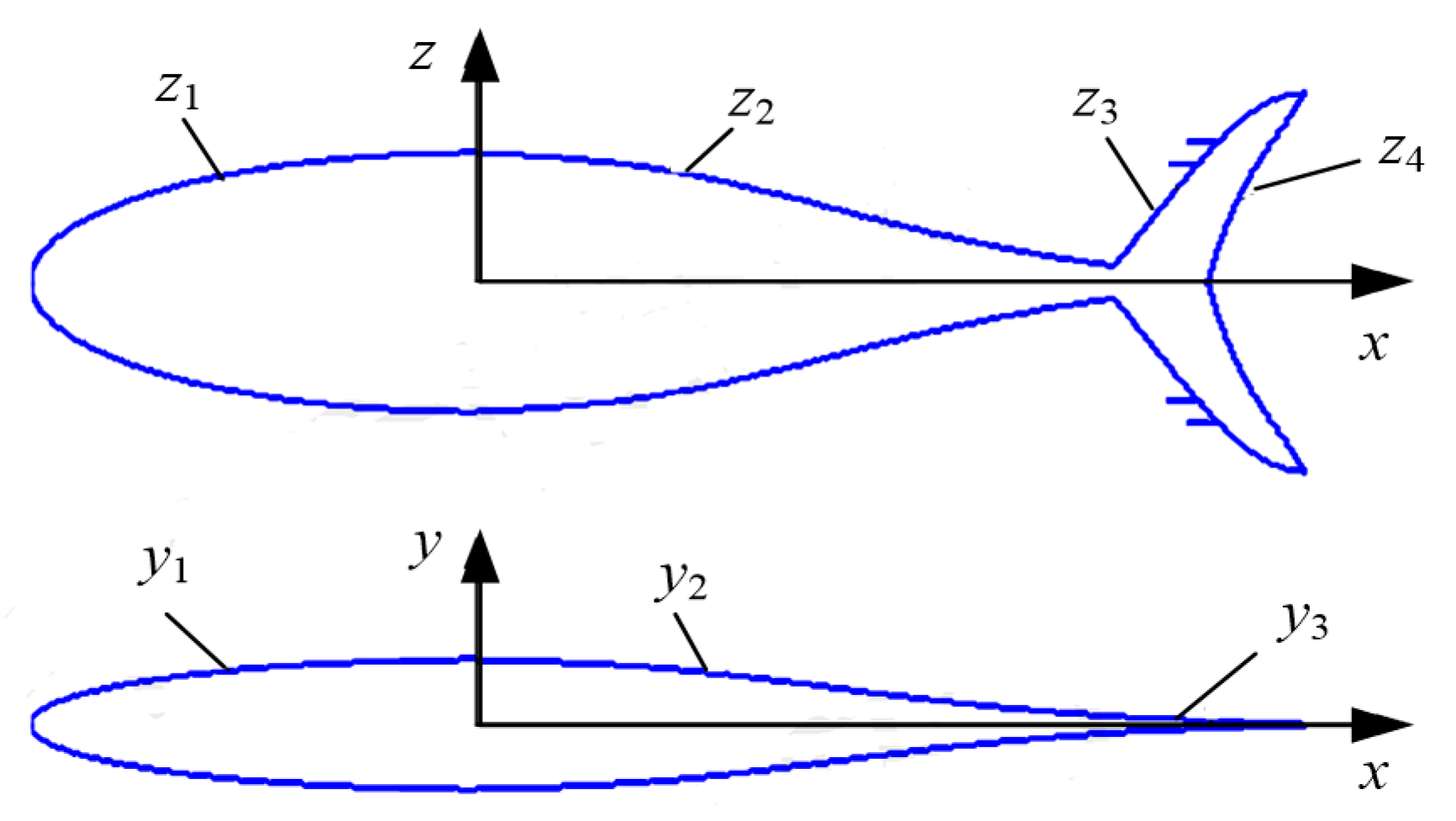
Figure 3.
Three-dimensional geometric model of the NACA foil.
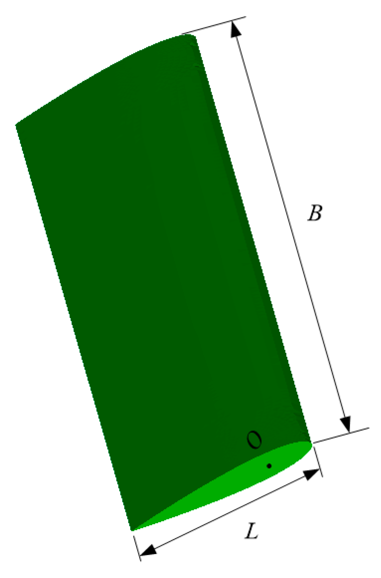
Figure 4.
Definitions of relevant motion parameters.
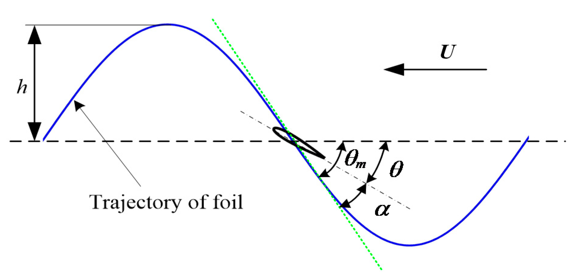
Figure 5.
Shape description of the flexible NACA foil.
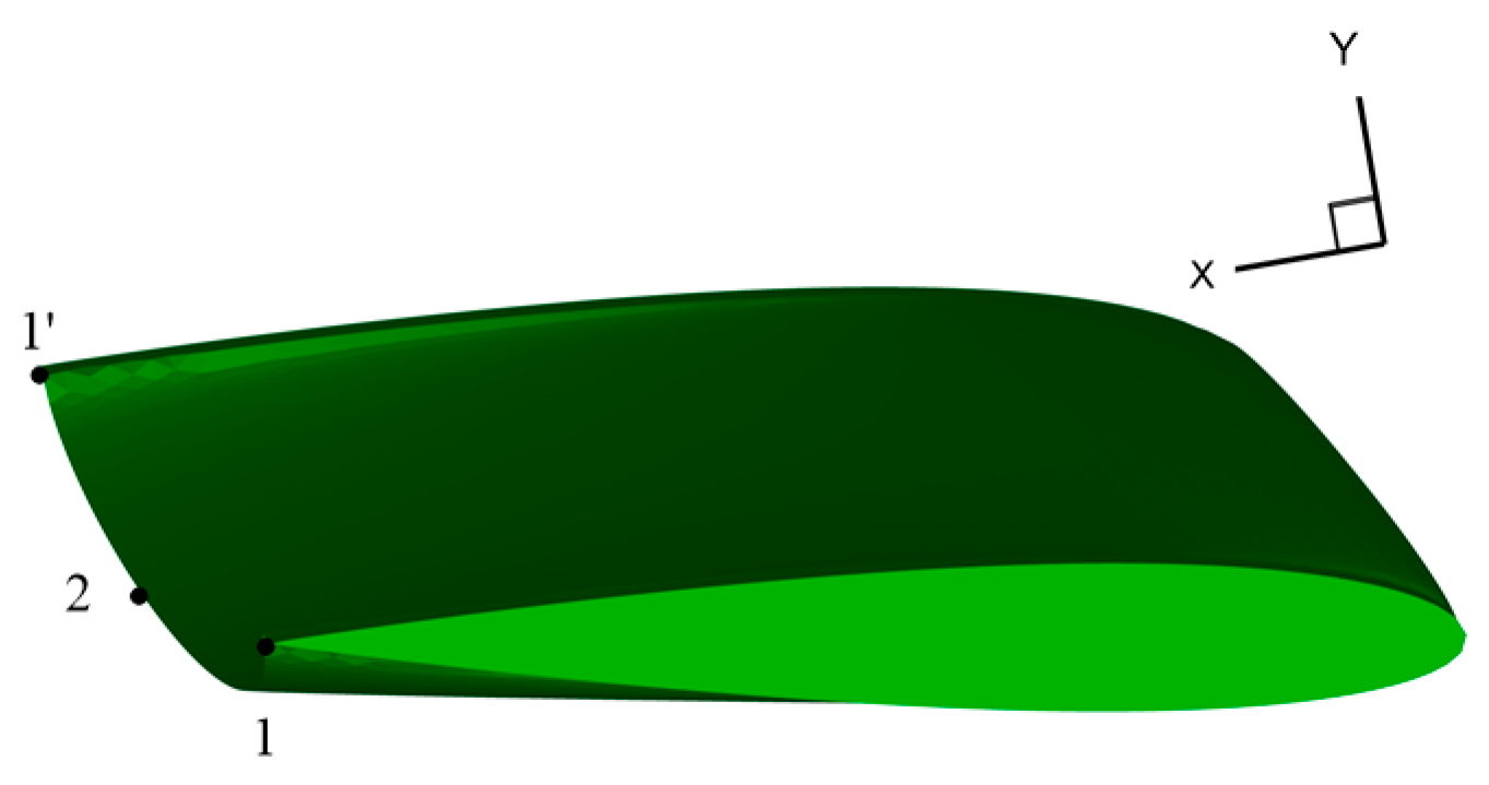
Figure 6.
Shape description of the flexible crescent-shaped foil: (a) γ = 20°; (b) γ = −20°.
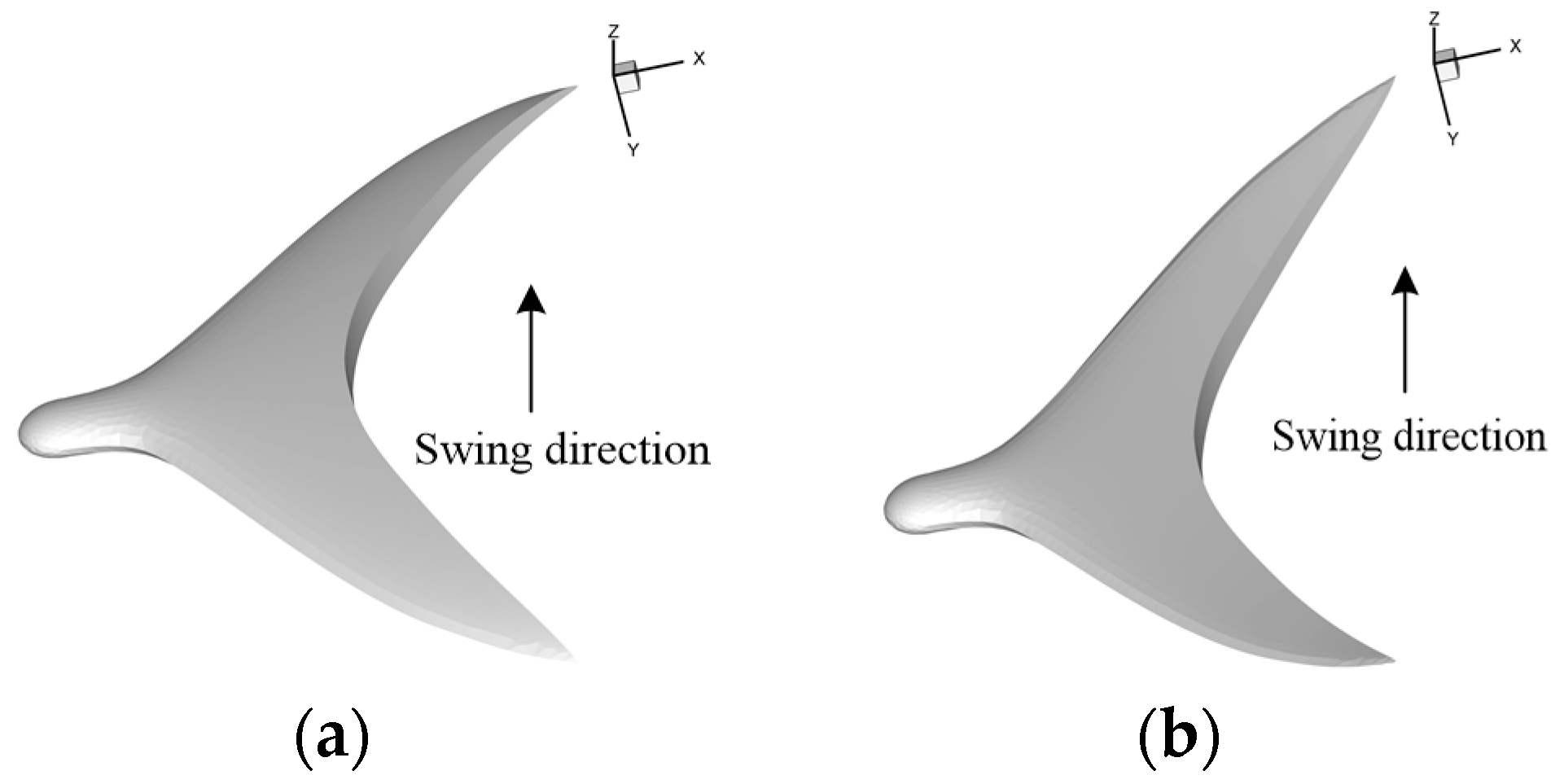
Figure 7.
Computational domain and grids of the thunniform bio-inspired mode: (a) computational domain; (b) grids.
Figure 7.
Computational domain and grids of the thunniform bio-inspired mode: (a) computational domain; (b) grids.
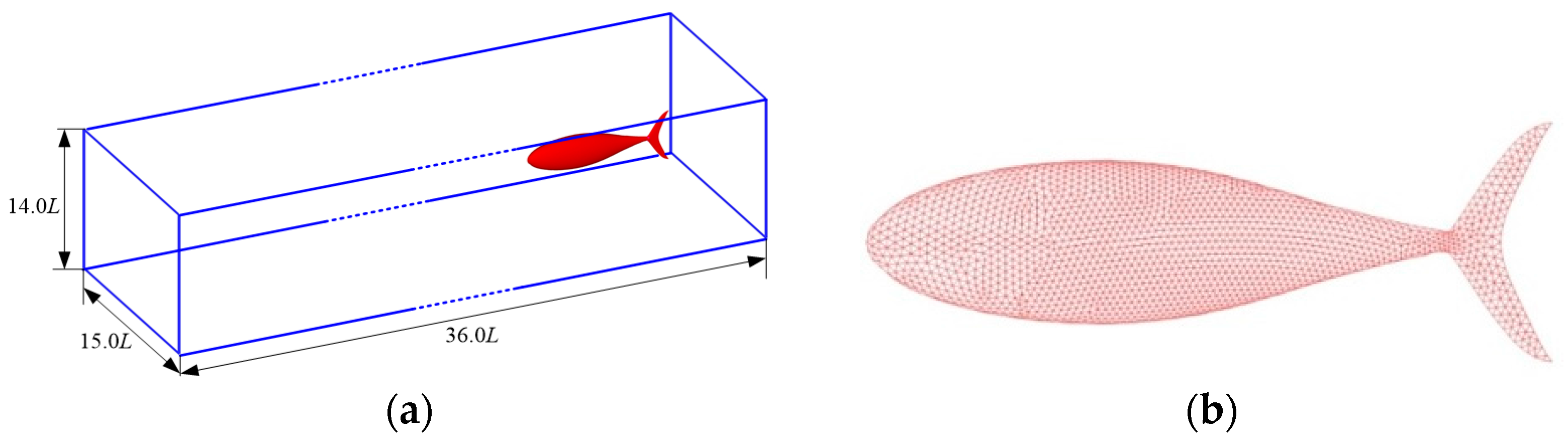
Figure 8.
Velocity time-histories of the thunniform bio-inspired mode.

Figure 9.
Vortex pattern in the wake of the thunniform bio-inspired mode: (a) three-dimensional case; (b) two-dimensional case.
Figure 9.
Vortex pattern in the wake of the thunniform bio-inspired mode: (a) three-dimensional case; (b) two-dimensional case.

Figure 10.
Forces and torque curves: (a) NACA foil; (b) crescent-shaped foil.

Figure 11.
Three-dimensional vortex patterns in the wake: (a) NACA foil; (b) crescent-shaped foil.

Figure 12.
Performance curves versus phase difference of the NACA foil: (a) mean thrust force coefficients; (b) propulsive efficiency.
Figure 12.
Performance curves versus phase difference of the NACA foil: (a) mean thrust force coefficients; (b) propulsive efficiency.

Figure 13.
Three-dimensional vortex pattern in the wake of the NACA foil: (a) γ = 20°; (b) γ = −20°.
Figure 13.
Three-dimensional vortex pattern in the wake of the NACA foil: (a) γ = 20°; (b) γ = −20°.
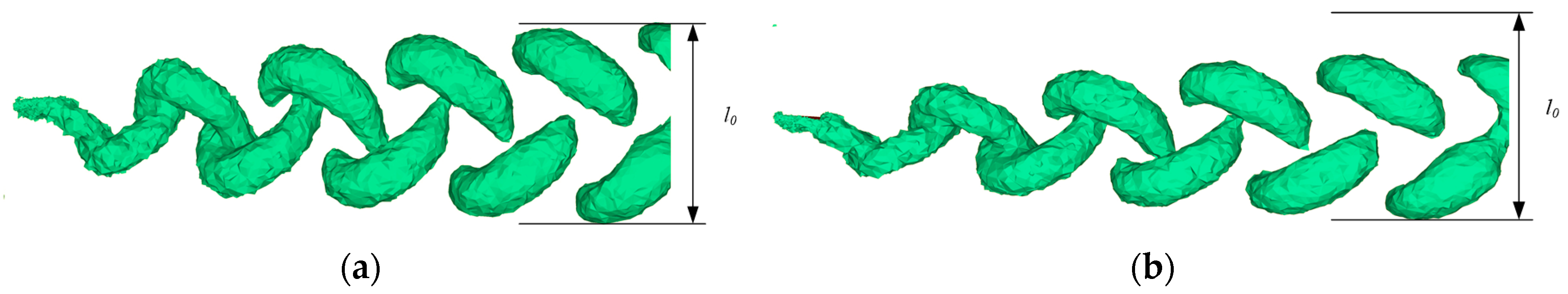
Figure 14.
Performance curves versus phase difference of the crescent-shaped foil: (a) mean thrust force coefficients; (b) propulsive efficiency.
Figure 14.
Performance curves versus phase difference of the crescent-shaped foil: (a) mean thrust force coefficients; (b) propulsive efficiency.

Figure 15.
Three-dimensional vortex pattern in the wake of the crescent-shaped foil: (a) γ = 20°; (b) γ = −20°.
Figure 15.
Three-dimensional vortex pattern in the wake of the crescent-shaped foil: (a) γ = 20°; (b) γ = −20°.

Figure 16.
Installation photo of the bionic foils: (a) NACA foil; (b) crescent-shaped foil.

Figure 17.
Comparison of experimental results and numerical results: (a) NACA foil; (b) crescent-shaped foil.
Figure 17.
Comparison of experimental results and numerical results: (a) NACA foil; (b) crescent-shaped foil.
© 2017 by the authors. Licensee MDPI, Basel, Switzerland. This article is an open access article distributed under the terms and conditions of the Creative Commons Attribution (CC BY) license (http://creativecommons.org/licenses/by/4.0/).
Share and Cite
MDPI and ACS Style
Zhou, K.; Liu, J.; Chen, W. Study on the Hydrodynamic Performance of Typical Underwater Bionic Foils with Spanwise Flexibility. Appl. Sci. 2017, 7, 1120. https://doi.org/10.3390/app7111120
AMA Style
Zhou K, Liu J, Chen W. Study on the Hydrodynamic Performance of Typical Underwater Bionic Foils with Spanwise Flexibility. Applied Sciences. 2017; 7(11):1120. https://doi.org/10.3390/app7111120
Chicago/Turabian StyleZhou, Kai, Junkao Liu, and Weishan Chen. 2017. "Study on the Hydrodynamic Performance of Typical Underwater Bionic Foils with Spanwise Flexibility" Applied Sciences 7, no. 11: 1120. https://doi.org/10.3390/app7111120
Note that from the first issue of 2016, this journal uses article numbers instead of page numbers. See further details here.