3-D Printed Fabry–Pérot Resonator Antenna with Paraboloid-Shape Superstrate for Wide Gain Bandwidth

School of Electrics and Information Engineering, Sichuan University, Chengdu 610064, China
*
Author to whom correspondence should be addressed.
Appl. Sci. 2017, 7(11), 1134; https://doi.org/10.3390/app7111134
Submission received: 23 September 2017
/
Revised: 22 October 2017
/
Accepted: 1 November 2017
/
Published: 4 November 2017
(This article belongs to the Special Issue 3D Printed Antennas)
Abstract
:A three-dimensional (3-D) printed Fabry–Pérot resonator antenna (FPRA), which designed with a paraboloid-shape superstrate for wide gain bandwidth is proposed. In comparison with the commonly-adopted planar superstrate, the paraboloid-shape superstrate is able to provide multiple resonant heights and thus satisfy the resonant condition of the FPRA in a wide frequency band. A FPRA working at 6 GHz is designed, fabricated, and tested. Considering the fabrication difficulty caused by its complex structure, the prototype antenna was fabricated by using the 3-D printing technology, i.e., all components of the prototype antenna were printed with photopolymer resin and then treated by the surface metallization process. Measurement results agree well with the simulation results, and show the 3-D printed FPRA has a |S11| < −10 dB impedance bandwidth of 12.4%, and a gain of 16.8 dBi at its working frequency of 6 GHz. Moreover, in comparison with the planar superstrate adopted in traditional FPRAs, the paraboloid-shape superstrate of the proposed FPRA significantly improves the 3-dB gain bandwidth from 6% to 22.2%.
1. Introduction
High gain antennas are desirable in many applications, such as radar, wireless communication and microwave power transmission. As a kind of widely used high gain antennas, the Fabry–Pérot resonant antenna (FPRA) is formed by placing a superstrate with partial reflection property in front of an excitation antenna with a ground plane [1,2,3,4,5]. Various antennas have been selected as the excitation antenna for the FPRA, such as the open waveguide antenna, the microstrip antenna, and the microstrip array antenna [1,4,6]. The superstrate could be a homogeneous dielectric substrate [3,7], or metamaterial inspired one, that is usually a printed circuit board (PCB) etched periodic microstrip unit cells [2,4,8,9]. In comparison with other high gain antennas such as parabolic antennas and microstrip array antennas, the FPRA possesses advantages of high gain, low profile, and high radiation efficiency.
The FPRA achieves a high gain owing to the multiple reflections between its superstrate and ground plane. By properly determining the distance between the superstrate and ground plane, the multiple reflections are able to create an in-phase electromagnetic (EM) field on its aperture, i.e., over its superstrate. However, the multiple reflections may cause a strong resonant property and thus lead to the FPRAs’ performances—such as the gain—being sensitive to the resonant height, i.e., the distance between the superstrate and the ground plane. So far, most FPRAs adopt a planar superstrate that means a fixed resonant height, and thus lead to a narrow gain bandwidth. For example, the 3-dB gain bandwidths of the FPRAs in [3,5,10] are 2, 1, and 0.8% respectively. As was pointed out in [11], the 3-dB gain bandwidth for a FPRA is usually less than 3%. The narrow gain bandwidth seriously limits the practical applications of the FPRAs.
Many technologies have been proposed to enhance the FPRAs’ gain bandwidth [6,7,8,12,13,14,15,16,17,18] and most of them can be divided into three categories. The first is adopting non-uniform superstrate or non-uniform ground plane, such as superstrate with tapered-sized FSS (frequency selective surface) or ground plane with tapered-sized HIS (high impedance surface) [7,12,13]. The second is designing superstrates with positive phase gradient, i.e., the superstrates’ reflection phase increasing with frequency [8,14,15,16,17]. The third is employing an antenna array instead of a single antenna as the excitation antenna to feed a FPRA [6,18].
Quite differently from the aforementioned technologies, this work explores enhancing the FPRAs’ gain bandwidth by designing a paraboloid-shape superstrate. Unlike planar superstrates used in most FPRAs, the cambered superstrate adopted by the proposed FPRA is able to create various resonant heights which satisfy the resonant conditions of the FPRA at a wide range of frequencies. To the best of our knowledge, this technology has never been investigated in previous studies.
To validate the proposed technology, a sample FPRA working at 6 GHz will be presented. Considering its complex structure, especially the paraboloid-shape superstrate, the prototype antenna will be fabricated by using the three-dimensional (3-D) printing technology. The 3-D printing technology also identified as additive manufacturing or rapid prototyping has been gradually used for fabricating microwave and millimeter components—such as antennas, filters, waveguides, 3-D metamaterials, etc. [19,20,21,22]—as it has the advantage of fabricating complex structures at a low cost. The 3-D printing technology enables designers have more freedom in their designs. The research work in [23] demonstrates the 3-D printed and surface metallized microwave components have nearly identical performances with solid metal structures if their skin depths of metal operate identically. Nowadays, by adopting some technologies such as using a beam of laser to solidify liquid photopolymer resin layer, a 3-D printing operation can achieve a very high printing precision of ±50 μm, while also guaranteeing good surface quality [24].
2. Resonant Condition for FPRA
As illustrated in Figure 1, a typical FPRA includes an excitation antenna, a superstrate and a ground. The EM energy emerges from the excitation antenna and undergoes multiple reflections between the superstrate and the ground. By using of the ray tracing model [1,16], assuming the EM ray is with an incident angle of θ, and denoting the ith transmitted ray to be Rayi (i = 0, 1, 2…), the phase difference between two adjacent rays can be expressed as
where k = 2πf/c is the wave number, f is the working frequency, c is the light velocity, and are the phases of reflection coefficients for the superstrate and the ground respectively, and H is the resonant height.
In order to obtain high gain at θ direction, all transmitted rays should be in phase, and hence the phase difference between two adjacent rays should be 2nπ (n = 0, 1, 2…). For most practical applications, the FPRAs are required to have maximum gain at the broadside direction (θ = 0), and hence the resonant height H should satisfy the resonant condition as
where n is usually chosen as 0 to realize a low profile for the FPRA.
For a perfect electric conducting (PEC) ground plane, its reflection phase is a constant of . The reflection phase of a superstrate normally varies with the frequency. Hence for a FPRA with a fixed resonant height H, the resonant condition illustrated by Equation (2) is satisfied only within a narrow frequency band. This is why most FPRAs have a narrow gain bandwidth. Moreover, it can be expected that the FPRA is able to achieve a wide gain bandwidth if the FPRA’s configuration provides multiple resonant heights.
3. Design of the Proposed FPRA with Wide Gain Bandwidth
3.1. Configuration of the Proposed FPRA
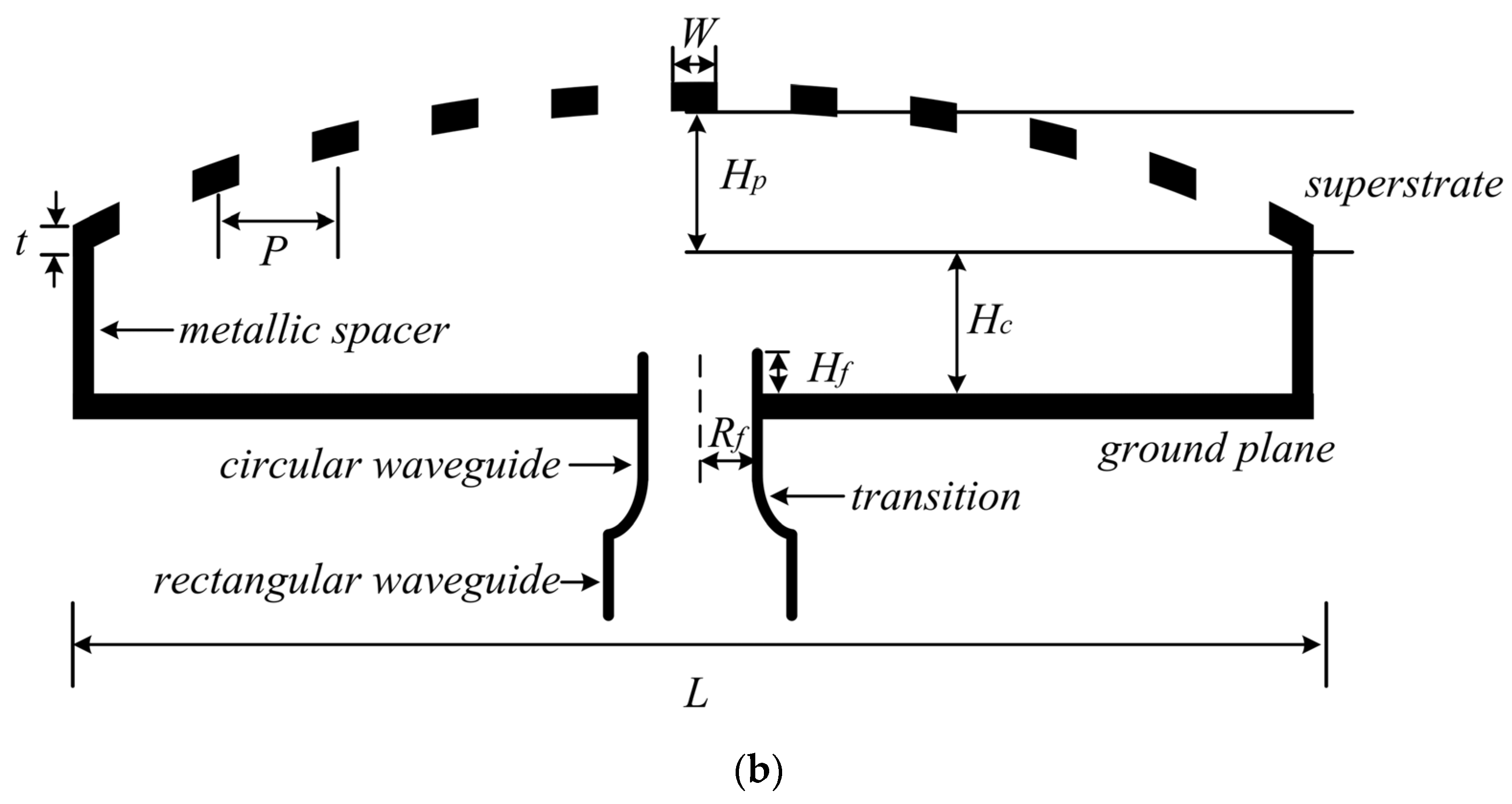
As shown in Figure 2, the proposed FPRA is mainly composed of a metallic grating superstrate with a paraboloidal shape, a ground plane, and an open-ended feeding circular waveguide acting as its excitation antenna. The FPRA is fed from a WR-159 standard rectangular waveguide, and a transition is connected between the circular and the rectangular waveguides. The circular superstrate diameter and thickness are L = 200 mm and thickness t = 2 mm. The width of the metallic strip and the spacing distance between two adjacent metallic strips are W = 5 mm and P = 20 mm, respectively. The heights of the cavity and the paraboloid-shape superstrate are Hc and Hp, respectively. The radius and insertion length of the feeding circular waveguide are Rf = 14.5 mm and Hf = 5 mm, respectively. The working frequency of the proposed FPRA is 6 GHz, and thus its diameter L of 200 mm corresponds to an electrical dimension of 4λ, where λ is the wavelength at 6 GHz in the free space.
3.2. FPRA with a Traditionial Planar Superstrate
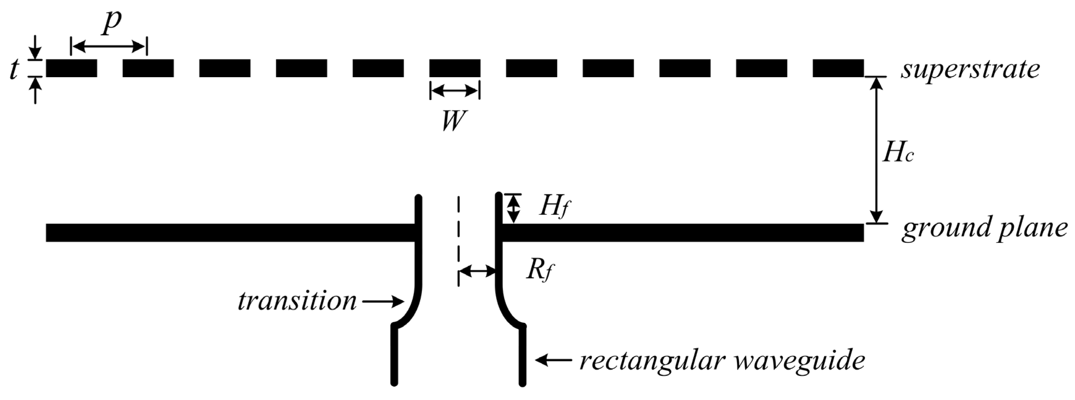
To provide a performance comparison, and moreover some necessary design data for the proposed FPRA, a FPRA with a traditional planar superstrate is designed first. This FPRA is also with a metallic grating superstrate. Except for the planar configuration of its superstrate, this antenna has the same structure (see Figure 3) and nearly the same parameters as that of the proposed FPRA with a paraboloid-shape superstrate.
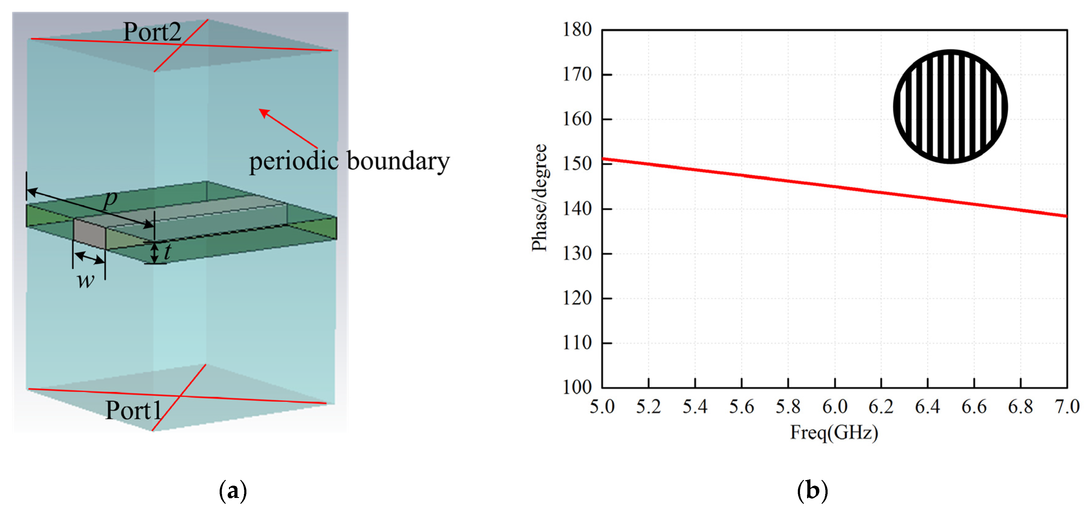
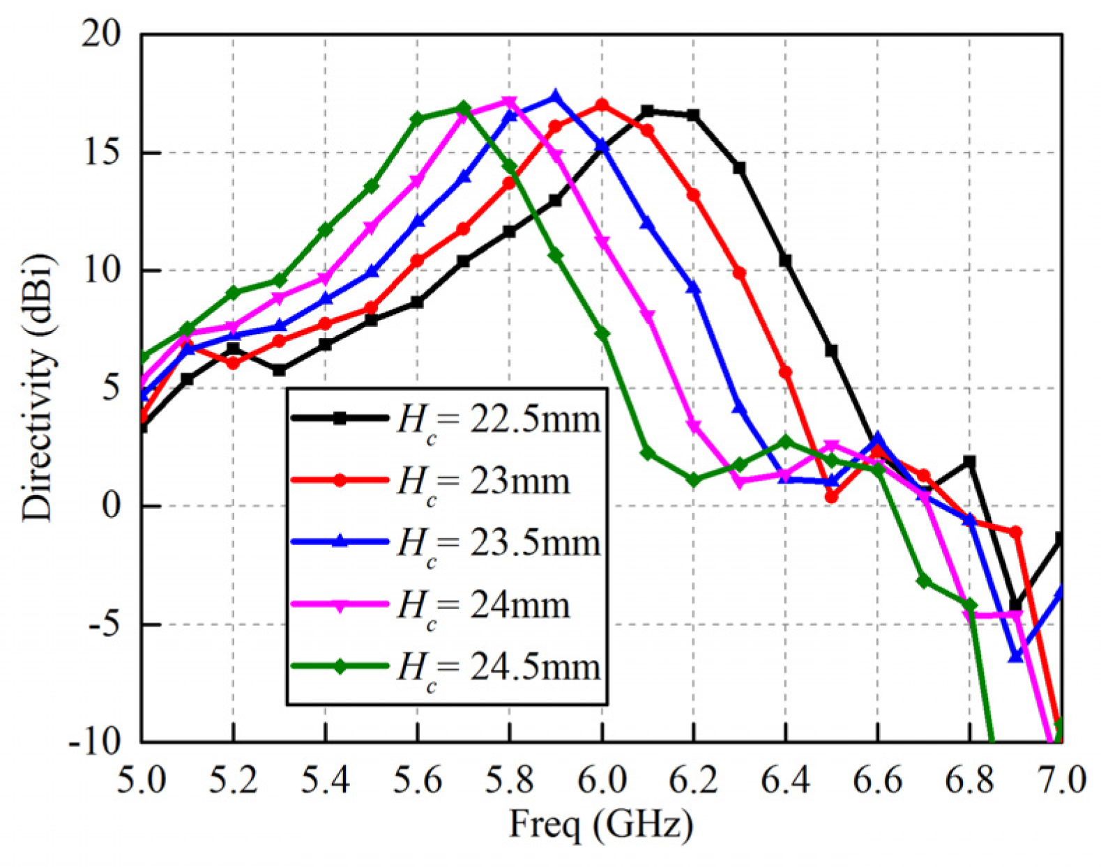
The unit cell of the planar metallic grating superstrate is illustrated in Figure 4a, by applying four periodic boundaries to surround the unit cell and two ports located above and below the unit cell, the reflection phase of the superstrate is calculated. Figure 4b shows the simulated reflection coefficient of the superstrate. As can be seen from Figure 4b, the reflection coefficient phase varies with frequency and its value is 145° at the working frequency 6 GHz. Then according to Equation (2), the resonant height Hc for the FPRA with a traditional planar superstrate is initially chosen to be 22.5 mm. To finely determine Hc, a popular commercial software CST (computer simulation technology) microwave studio (MWS) based on the finite integration technique (FIT) is employed, and the gain against Hc is simulated, as shown in Figure 5. Obviously, the optimal value of Hc is 23 mm, which corresponds to a peak gain of 17 dBi at the working frequency of 6 GHz. The 3-dB gain bandwidth for this PPRA is narrow as can be seen in Figure 5, only about 6% (from 5.81 GHz to 6.17 GHz).
3.3. Proposed FPRA with a Paraboloid-Shpae Superstrate
To broaden the gain bandwidth of the FPRA, a paraboloid-shape superstrate is designed to replace the traditional planar superstrate. Compared to a planar one, a cambered superstrate provides multiple resonant heights, and thereby satisfies the resonant condition in a wide frequency band.
Figure 7 gives the simulated gain–frequency response against Hp for the proposed FPRA. One can observe that the higher Hp (from 4 mm to 12 mm), the wider gain bandwidth can be achieved, but the peak gain will drop slightly. When Hp is up to 10 mm, the increase of Hp will not bring the improvement of bandwidth any more. For the purpose of wideband and high-gain performance, Hp is set as 10 mm.
4. Fabrication, Measurements, and Discussion
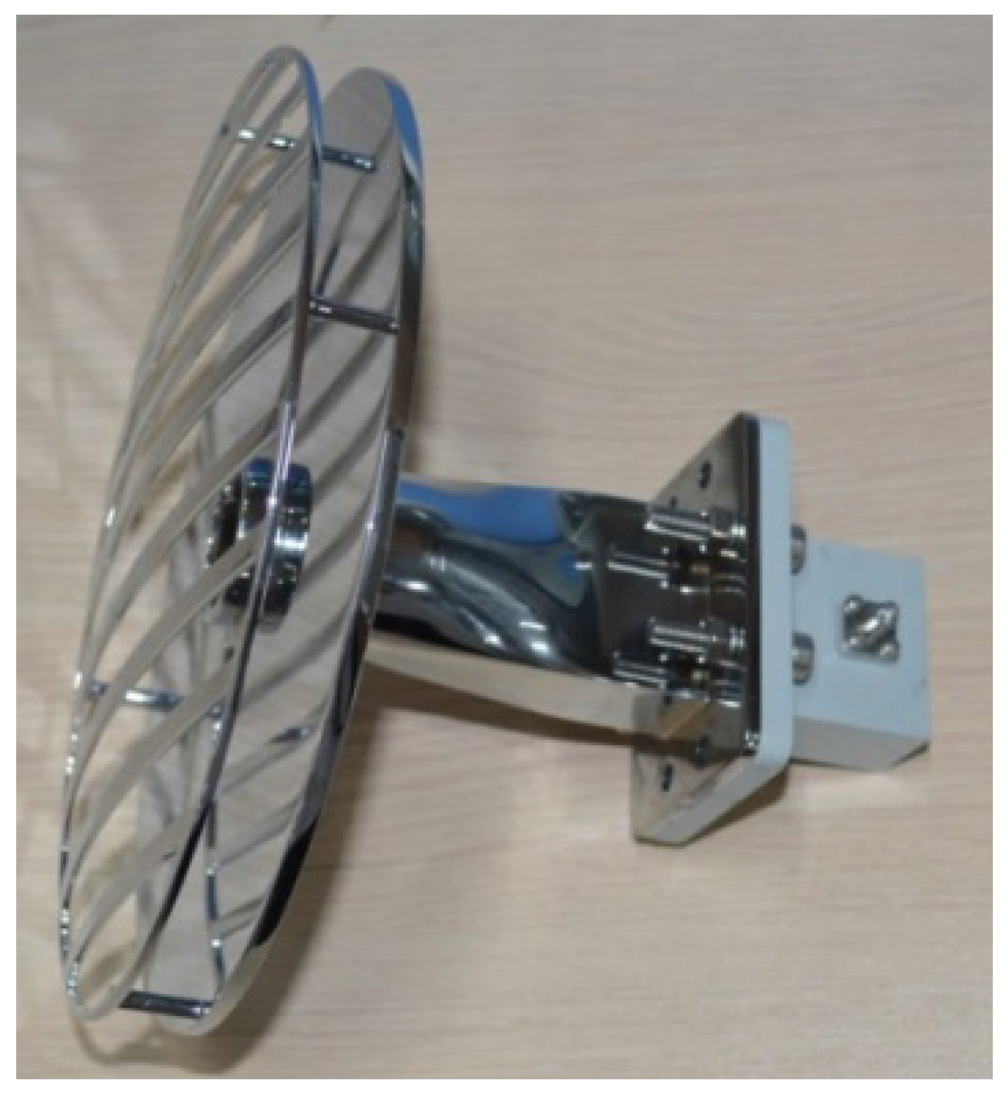
To validate the proposed FPRA, a prototype antenna will be fabricated and tested. The complex structure, especially the paraboloid-shape superstrate, may make the fabrication very difficult. Hence 3-D printing technology is employed to fabricate the proposed antenna (see Figure 8). In this work, all components of the proposed antenna are printed using a laser to solidify liquid photopolymer resin which is then treated by the surface metallization including the following step: (1) the printing material of resin is treated by a sequence of chemicals to activate the material’s surface; (2) 0.5 μm of Ni is electrolessly plated on the surface, the Ni serves as a seed layer for the later process; (3) 1–2 μm copper is elecrolessly plated above the surface of Ni; (4) 6 μm of copper is electroplated to increase the thickness of the copper and guarantee the layer is much larger than the skin depth (the value is 0.84 μm for copper at 6 GHz); (5) finally, 0.15 μm of silver is plated on the surface of the copper to prevent oxidation.
For the 3-D printed antenna, its input reflection coefficient was measured with an Agilent network analyzer N5230A. The simulated and measured |S11| are plotted and compared in Figure 9. The measured results are in good agreement with simulated ones, and indicate a |S11| < −10 dB impedance bandwidth of about 12.4% (from 5.8 GHz to 6.53 GHz).
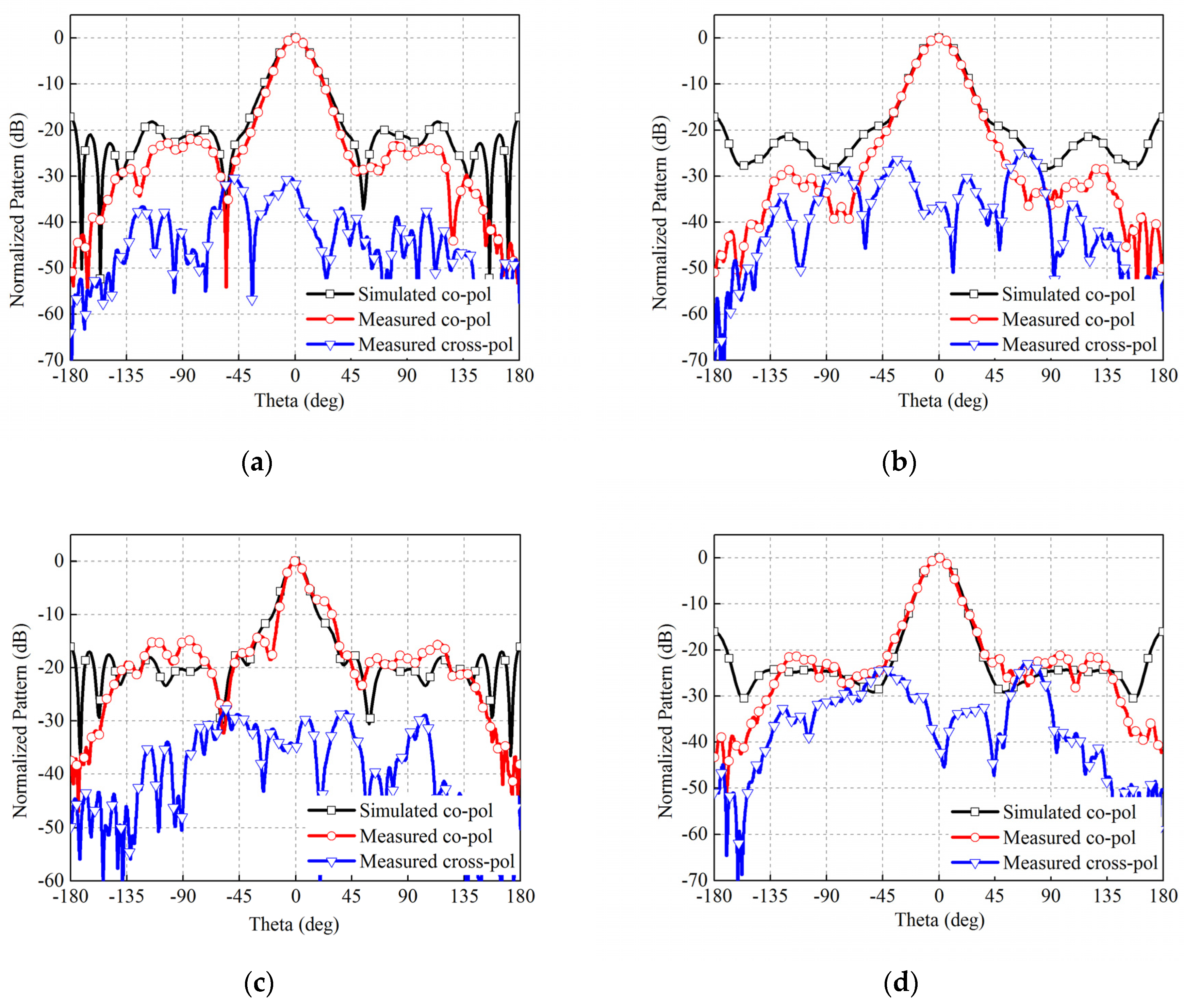
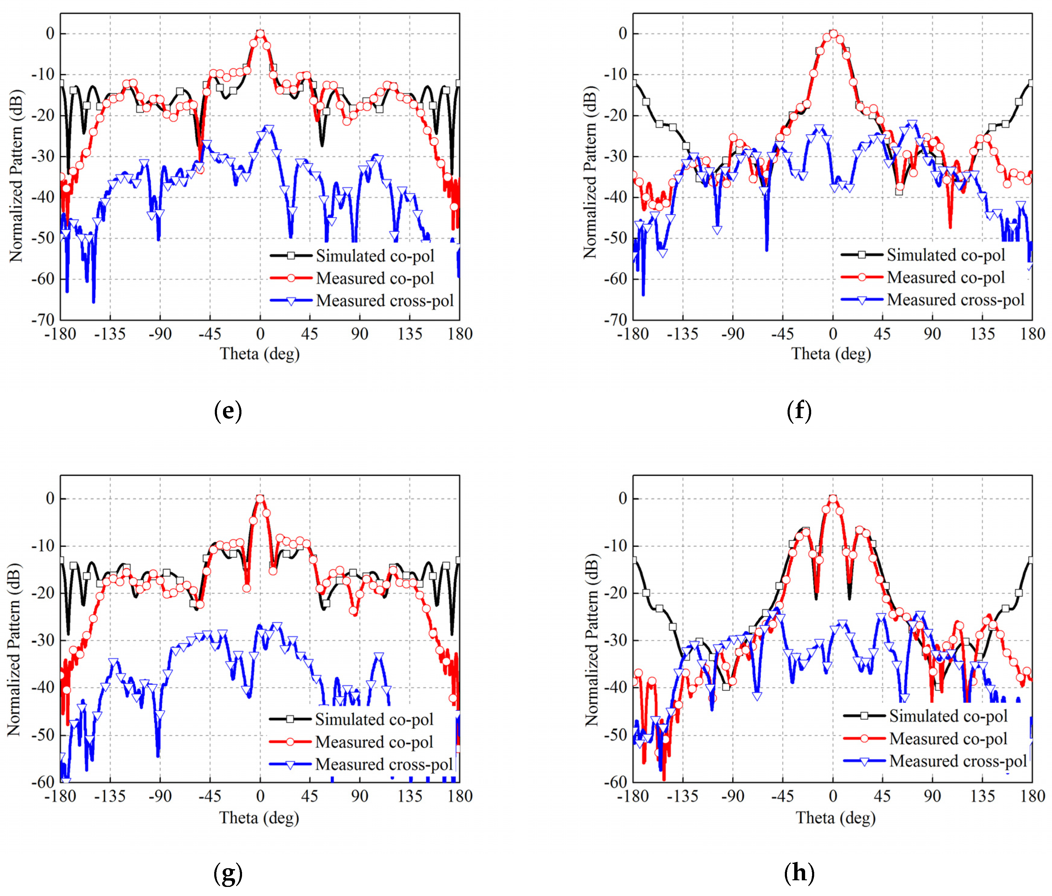
The radiation pattern of the 3-D printed antenna is measured in an anechoic chamber. Figure 10 plots the co-polarization and cross-polarization in E-plane and H-plane at 5.8, 6, 6.2, and 6.5 GHz respectively. It can be observed that the proposed FPRA performs good directive radiation patterns at all of those frequency points. The measured cross polarizations are also presented, which are less than −25 dB at the broadside. The polarization of the FPRA is consistent with that of the feeding antenna, which can be easily changed by employing a feeding antenna with a different polarization. With the increase of frequency, the side-lobe levels are also increased, this phenomenon has been observed with many wideband Fabry–Pérot resonator antennas [25].
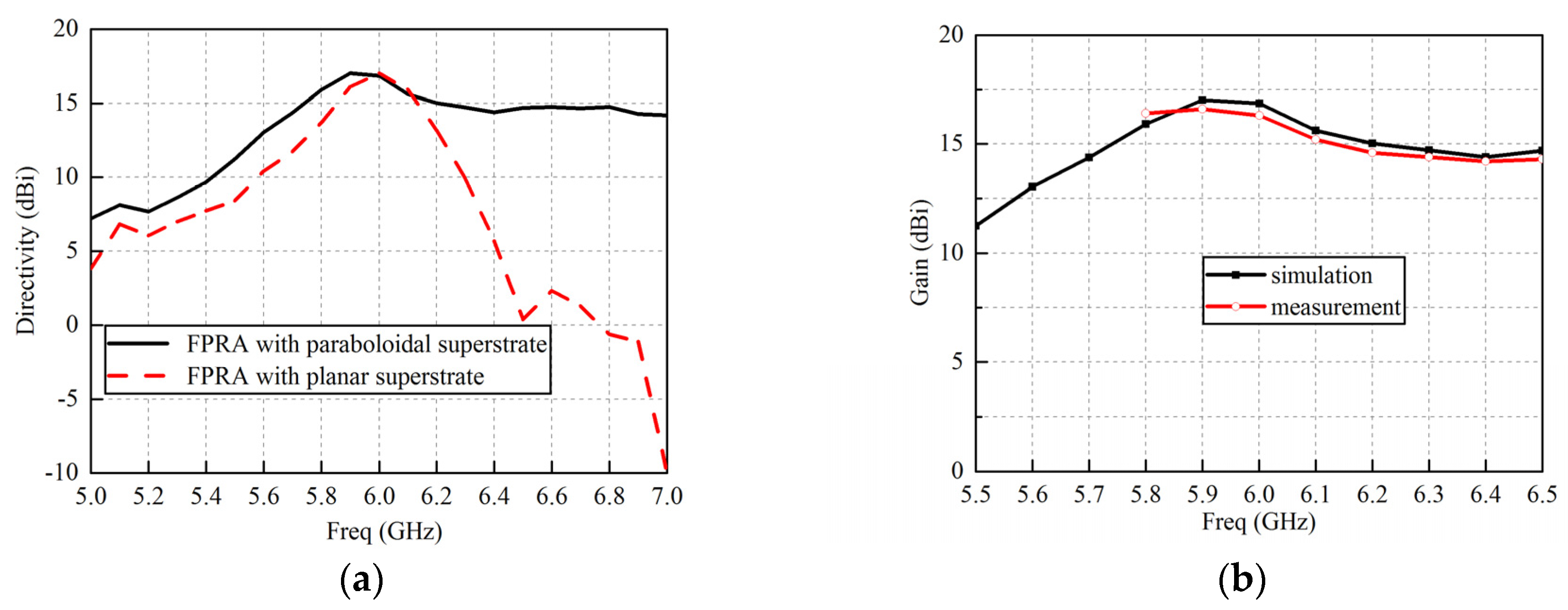
The simulated gains against the frequency for the proposed FPRA with a paraboloid-shape superstrate and the FPRA with a traditional planar superstrates are presented and compared in Figure 11a. The 3-dB gain bandwidths for those two FPRAs are 22.2% (from 5.67 to 7 GHz) and 6% (from 5.81 to 6.17 GHz), respectively. It is obvious that the paraboloidal superstrate significantly improves the gain bandwidth in comparison with a traditional planar one. Figure 11b compares the simulated and measured gain–frequency response for the proposed FPRA, one can observe they are in good agreement.
Table 1 lists 3-dB gain bandwidths of a few FPRAs designed in previous literatures, and are compared to that in this work. One can observe that the FPRA proposed in this work achieves a larger 3-dB gain bandwidth than those FPRAs in previous studies.
5. Conclusions
For the FPRA, the wide bandwidth is an attractive property in many applications. A novel technology of designing a paraboloid-shape superstrate to enhance the gain bandwidth of the FPRA is proposed. Compared to a traditional planar superstrate, this cambered superstrate is able to produce multiple resonant heights, and thereby satisfy the resonant condition in a much wider frequency range. In this work, a sample FPRA working at 6 GHz is designed and tested, and the 3-D printing technology is employed for fabricating the prototype antenna. For this 3-D printed antenna, its measured results agree well with the simulated ones, which demonstrate the high fabrication precision of the 3-D printing technology. Moreover, in comparison with the traditional planar superstrate, the proposed paraboloid-shape superstrate significantly improves the FPRA’s 3-dB gain bandwidth from 6% to 22.2%.
Acknowledgments
This work was supported by the China NSAF Fund under Grant U1230112.
Author Contributions
Q.C. proposed the idea and designed the antenna in the study and K.X. performed the experiment measurements and data processing. Q.C. and X.C. wrote and revised the paper. All authors read and approved the manuscript for publication.
Conflicts of Interest
The authors declare no conflict of interest.
References
- Trentini, G.V. Partially reflecting sheet arrays. IRE Trans. Antennas Propag. 1956, 4, 666–671. [Google Scholar] [CrossRef]
- Feresidis, A.P.; Vardaxoglou, J.C. High gain planar antenna using optimised partially reflective surfaces. IEE Proc. Microw. Antennas Propag. 2001, 148, 345–350. [Google Scholar] [CrossRef]
- Weily, A.R.; Esselle, K.P.; Sanders, B.C.; Bird, T.S. High-gain 1D EBG resonator antenna. Microwave Opt. Technol. Lett. 2005, 47, 107–114. [Google Scholar] [CrossRef]
- Chen, X.; Luo, Z.; Zheng, Z.; Feng, P.; Huang, K. Effective reflective characteristics of superstrates and their effects on the resonant cavity antenna. IEEE Trans. Antennas Propag. 2015, 63, 1572–1580. [Google Scholar] [CrossRef]
- Weily, A.R.; Horvath, L.; Esselle, K.P.; Sanders, B.C.; Bird, T.S. A planar resonator antenna based on a woodpile EBG material. IEEE Trans. Antennas Propag. 2005, 53, 216–223. [Google Scholar] [CrossRef]
- Vaidya, A.R.; Gupta, R.K.; Mishra, S.K.; Mukherjee, J. High-gain low side lobe level fabry perot cavity antenna with feed patch array. Prog. Electromagn. Res. C 2012, 28, 223–238. [Google Scholar] [CrossRef]
- Li, Y.; Mittra, R.; Zeng, B.; Lu, G.; Li, Z.; Liu, J.; Chang, D.C. Directivity enhancement of fabry-perot antenna by using a stepped-dielectric slab superstrate. Microw. Opt. Technol. Lett. 2012, 54, 711–715. [Google Scholar] [CrossRef]
- Ge, Y.; Esselle, K.P.; Bird, T.S. The use of simple thin partially reflective surfaces with positive reflection phase gradients to design wideband, low-profile EBG resonator antennas. IEEE Trans. Antennas Propag. 2012, 60, 743–750. [Google Scholar] [CrossRef]
- Liu, Z.G. Fabry-Perot resonator antenna. J. Infrared Millim. Terahertz Waves 2010, 31, 391–403. [Google Scholar] [CrossRef]
- Guérin, N.; Enoch, S.; Tayeb, G.; Sabouroux, P.; Vincent, P.; Legay, H. A metallic Fabry-Perot directive antenna. IEEE Trans. Antennas Propag. 2006, 54, 220–224. [Google Scholar] [CrossRef]
- Hashmi, R.M.; Esselle, K.P. A class of extremely wideband resonant cavity antennas with large directivity-bandwidth products. IEEE Trans. Antennas Propag. 2016, 64, 830–835. [Google Scholar] [CrossRef]
- Liu, Z.; Zhang, W.; Fu, D.; Gu, Y.; Ge, Z. Broadband Fabry-Perot resonator printed antennas using FSS superstrate with dissimilar size. Microw. Opt. Technol. Lett. 2008, 50, 1623–1627. [Google Scholar] [CrossRef]
- Yeo, J.; Kim, D. Novel design of a high-gain and wideband Fabry-Perot cavity antenna using a tapered AMC substrate. J. Infrared Millim. Terahertz Waves 2009, 30, 217–224. [Google Scholar] [CrossRef]
- Wang, N.; Liu, Q.; Wu, C.; Talbi, L.; Zeng, Q.; Xu, J. Wideband Fabry-Perot resonator antenna with two complementary FSS layers. IEEE Trans. Antennas Propag. 2014, 62, 2463–2471. [Google Scholar]
- Wang, N.; Li, J.; Wei, G.; Talbi, L.; Zeng, Q.; Xu, J. Wideband Fabry–Perot resonator antenna with two layers of dielectric superstrates. IEEE Antennas Wirel. Propag. Lett. 2015, 14, 229–232. [Google Scholar] [CrossRef]
- Feresidis, A.P.; Vardaxoglou, J.C. A broadband high-gain resonant cavity antenna with single feed. In Proceedings of the European Conference on Antennas and Propagation, Nice, France, 6–10 November 2006; Volume 626, pp. 1–5. [Google Scholar]
- Konstantinidis, K.; Feresidis, A.P.; Hall, P.S. Multilayer partially reflective surfaces for broadband Fabry-Perot cavity antennas. IEEE Trans. Antennas Propag. 2014, 62, 3474–3481. [Google Scholar] [CrossRef]
- Weily, A.R.; Esselle, K.P.; Bird, T.S.; Sanders, B.C. Dual resonator 1-D EBG antenna with slot array feed for improved radiation bandwidth. IET Microw. Antennas Propag. 2007, 1, 198–203. [Google Scholar] [CrossRef]
- Du, G.; Liang, M.; Sabory-Garcia, R.A.; Liu, C.; Xin, H. 3-D printing implementation of an X-band Eaton lens for beam deflection. IEEE Antennas Wirel. Propag. Lett. 2016, 15, 1487–1490. [Google Scholar] [CrossRef]
- Guo, C.; Shang, X.; Li, J.; Zhang, F.; Lancaster, M.J.; Xu, J. A Lightweight 3-D Printed X-Band Bandpass Filter Based on Spherical Dual-Mode Resonators. IEEE Microw. Wirel. Compon. Lett. 2016, 26, 568–570. [Google Scholar] [CrossRef]
- Zhang, B.; Zirath, H. Metallic 3-D printed rectangular waveguides for millimeter-wave applications. IEEE Trans. Compon. Packag. Manuf. Technol. 2016, 6, 796–804. [Google Scholar] [CrossRef]
- Barton, J.H.; Garcia, C.R.; Berry, E.A.; Salas, R.; Rumpf, R.C. 3-D printed all-dielectric frequency selective surface with large bandwidth and field of view. IEEE Trans. Antennas Propag. 2015, 63, 1032–1039. [Google Scholar] [CrossRef]
- Sage, G.P.L. 3D printed waveguide slot array antennas. IEEE Access 2016, 4, 1258–1265. [Google Scholar] [CrossRef]
- Chieh, J.C.S.; Dick, B.; Loui, S.; Rockway, J.D. Development of a ku-band corrugated conical horn using 3-d print technology. IEEE Antennas Wirel. Propag. Lett. 2014, 13, 201–204. [Google Scholar] [CrossRef]
- Moustafa, L.; Jecko, B. Broadband high gain compact resonator antennas using combined FSS. In Proceedings of the Antennas and Propagation Society International Symposium, San Diego, CA, USA, 5–11 July 2008; pp. 1–4. [Google Scholar]
Figure 1.
Schematic view of the ray tracing model for Fabry–Pérot resonator antenna.
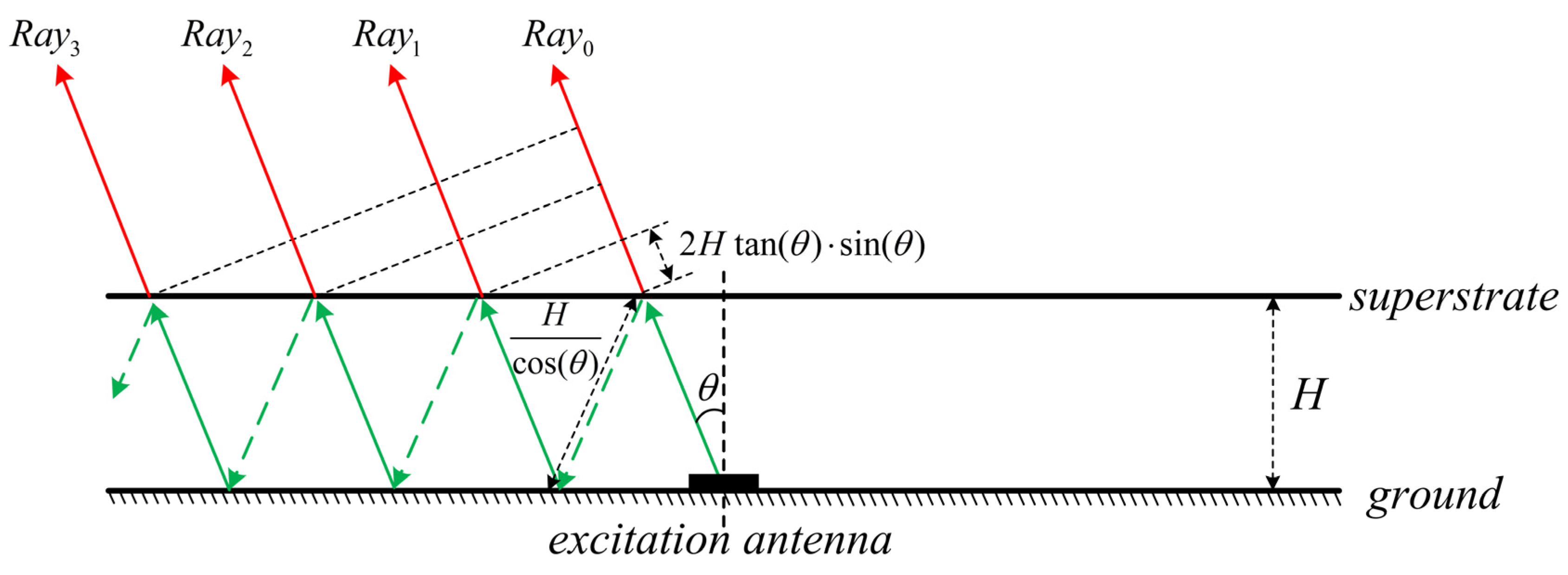
Figure 2.
Configuration of the proposed FPRA. (a) 3-D view; (b) cross-section view with main structural parameters.
Figure 2.
Configuration of the proposed FPRA. (a) 3-D view; (b) cross-section view with main structural parameters.
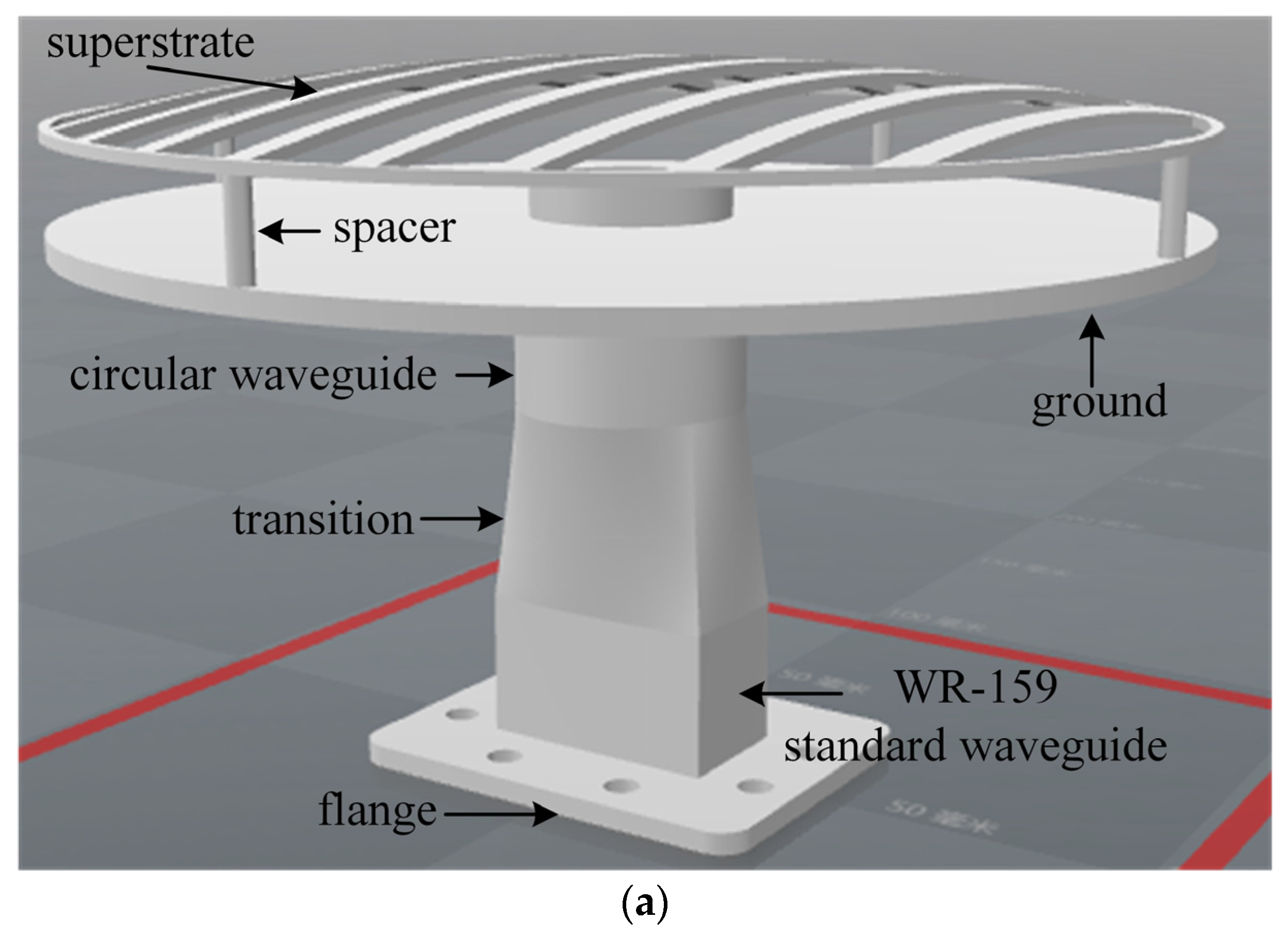

Figure 3.
Cross-section of the FPRA with a planar superstrate.

Figure 4.
(a) Simulation model of the unit cell; (b) reflection phase of the planar superstrate.

Figure 5.
Gain-frequency response against Hc for the FRPA with a traditional planar superstrate.

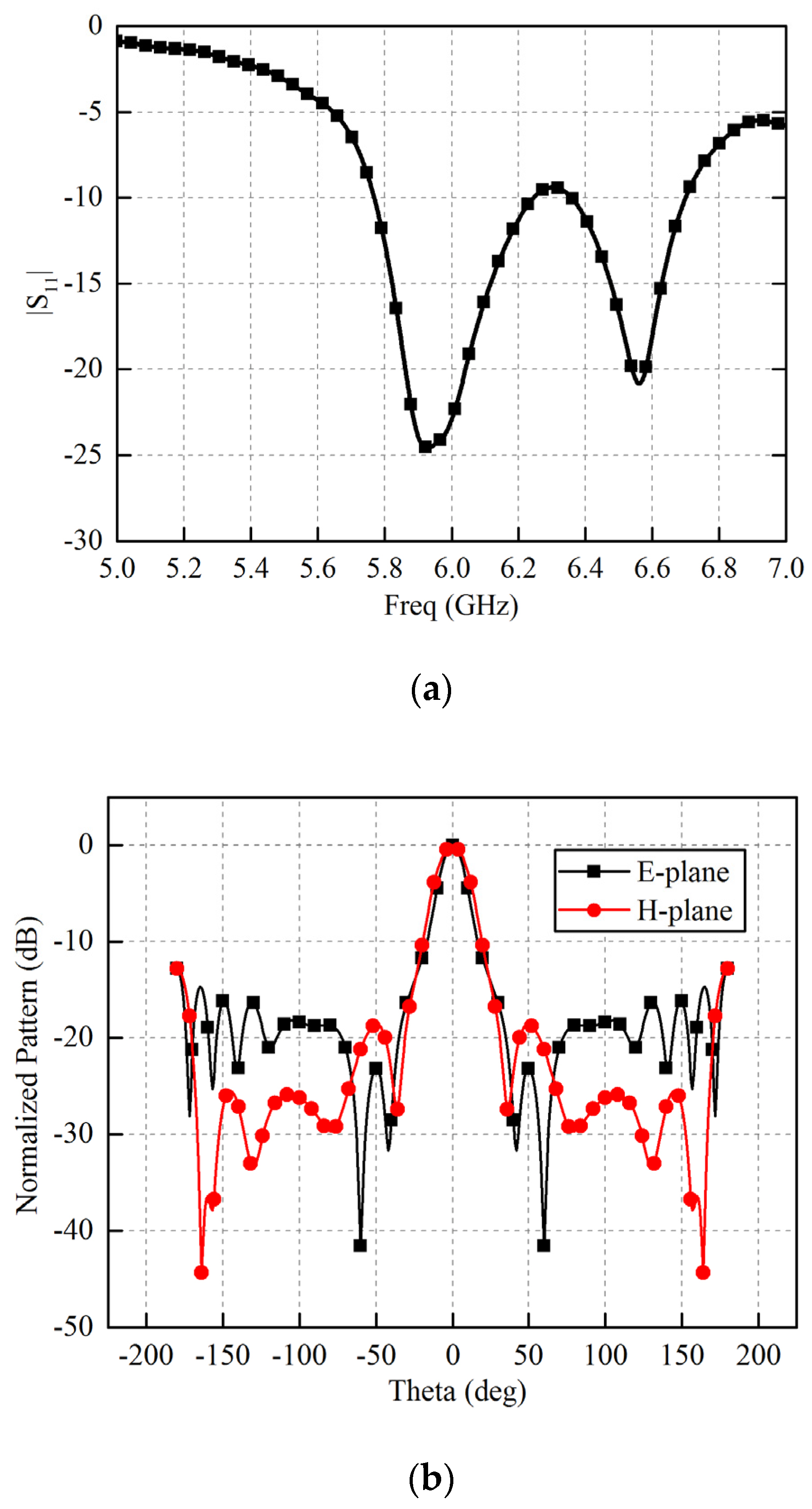
Figure 6.
Simulated performances of the FPRA with a traditional planar superstrate. (a) |S11|; (b) radiation pattern at 6 GHz.
Figure 6.
Simulated performances of the FPRA with a traditional planar superstrate. (a) |S11|; (b) radiation pattern at 6 GHz.

Figure 7.
Gain-frequency response against Hp for proposed FPRA.
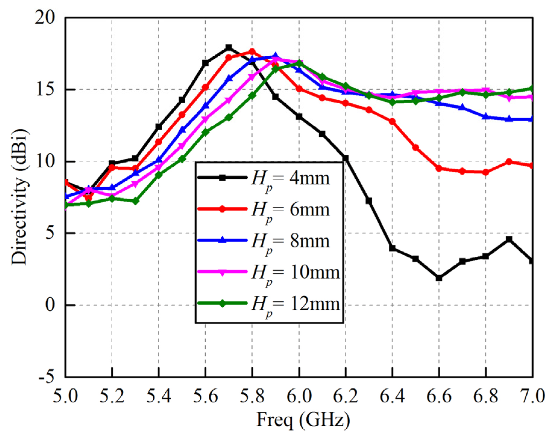
Figure 8.
Photograph of the proposed 3-D printed antenna. A waveguide to coaxial connector is used to feed the antenna.
Figure 8.
Photograph of the proposed 3-D printed antenna. A waveguide to coaxial connector is used to feed the antenna.

Figure 9.
Simulated and measured reflection coefficients for the proposed FPRA.
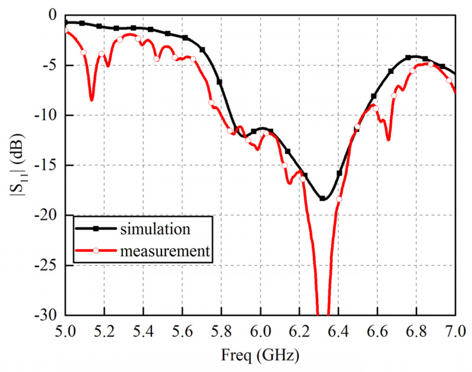
Figure 10.
Normalized radiation patterns of the proposed FPRA: (a) E-plane at 5.8 GHz; (b) H-plane at 5.8 GHz; (c) E-plane at 6 GHz; (d) H-plane at 6 GHz; (e) E-plane at 6.2 GHz; (f) H-plane at 6.2 GHz; (g) E-plane at 6.5 GHz; and (h) H-plane at 6.5 GHz.
Figure 10.
Normalized radiation patterns of the proposed FPRA: (a) E-plane at 5.8 GHz; (b) H-plane at 5.8 GHz; (c) E-plane at 6 GHz; (d) H-plane at 6 GHz; (e) E-plane at 6.2 GHz; (f) H-plane at 6.2 GHz; (g) E-plane at 6.5 GHz; and (h) H-plane at 6.5 GHz.


Figure 11.
(a) Gain bandwidth comparison between FPRA with planar superstrate and paraboloidal superstrate; (b) simulated and measured gain–frequency response for the proposed FPRA.
Figure 11.
(a) Gain bandwidth comparison between FPRA with planar superstrate and paraboloidal superstrate; (b) simulated and measured gain–frequency response for the proposed FPRA.

Table 1.
Comparison of the 3-dB gain bandwidth between a few FPRAs in literatures and the FPRA proposed in this work.
© 2017 by the authors. Licensee MDPI, Basel, Switzerland. This article is an open access article distributed under the terms and conditions of the Creative Commons Attribution (CC BY) license (http://creativecommons.org/licenses/by/4.0/).
Share and Cite
MDPI and ACS Style
Chen, Q.; Chen, X.; Xu, K. 3-D Printed Fabry–Pérot Resonator Antenna with Paraboloid-Shape Superstrate for Wide Gain Bandwidth. Appl. Sci. 2017, 7, 1134. https://doi.org/10.3390/app7111134
AMA Style
Chen Q, Chen X, Xu K. 3-D Printed Fabry–Pérot Resonator Antenna with Paraboloid-Shape Superstrate for Wide Gain Bandwidth. Applied Sciences. 2017; 7(11):1134. https://doi.org/10.3390/app7111134
Chicago/Turabian StyleChen, Qiang, Xing Chen, and Ke Xu. 2017. "3-D Printed Fabry–Pérot Resonator Antenna with Paraboloid-Shape Superstrate for Wide Gain Bandwidth" Applied Sciences 7, no. 11: 1134. https://doi.org/10.3390/app7111134
Note that from the first issue of 2016, this journal uses article numbers instead of page numbers. See further details here.