Article

Control Strategies for Enhancing Frequency Stability by DFIGs in a Power System with High Percentage of Wind Power Penetration

by
Reza Kazemi Golkhandan
,
Mohammad R. Aghaebrahimi
* and
Mohsen Farshad
Faculty of Electrical & Computer Engineering, University of Birjand, Birjand 97175, Iran
*
Author to whom correspondence should be addressed.
Appl. Sci. 2017, 7(11), 1140; https://doi.org/10.3390/app7111140
Submission received: 8 October 2017 / Revised: 28 October 2017 / Accepted: 2 November 2017 / Published: 6 November 2017
(This article belongs to the Section Energy Science and Technology)

Abstract

:
Nowadays, regarding high percentage of wind power penetration in power systems, operating conditions of power system necessitates wind turbine generators (WTGs) to contribute in frequency regulation of the system, similar to the conventional units. To reach this goal, active power output of WTGs must be controlled, but this issue distances the operating conditions of WTGs from maximum power point tracking (MPPT) mode. This paper initially presents a completed model of doubly fed induction generator (DFIG) for dynamic studies in frequency stability analysis. Next, a coordinated control strategy to regulate active power command set point (Pcmd) for individual WTGs in a wind farm (WF) and a control strategy to regulate wind power output of DFIG upon operator’s request is presented. Stability is assured under different wind conditions in the proposed control strategy. Individual WTGs set point allocation is performed applying fuzzy logic controller (FLC), while emotional learning based intelligent controller is used in regulation of the coefficient in the DFIG to reach the best stability conditions. Simulation results, performed on a test system consisting of both conventional units and WTGs, validate the effectiveness of the proposed control strategy in comparison with other mentioned solutions.

1. Introduction

Wind power penetration in power systems has been rapidly growing in recent years. Regarding environmental pollution of conventional generating units and economic benefits of fuel savings, there has been a great concern toward renewable energy sources [1]. Thus, with improving techniques, reducing costs and low environmental contact, wind energy seems to play an important role in the future of world energy supply [2].
In earlier projects, wind turbine generators (WTGs) were not committed to grid operation. By improving wind power generation, most of the installation projects were oriented towards large-scale wind farms (WFs) interconnected to the power system [3]. Reduction of conventional generating units in the power system results in reduction of system inertia and hence the overall system frequency will be affected. Frequency stability studies related to utilization of WTGs alongside the conventional generating units have grown in recent years. It is of special interest to consider the impact of wind power on power system operation and stability [2]. Currently, most WFs are operating in the mode of maximum power point tracking (MPPT). This operating condition is beneficial from the economic point of view, but there exists a great disadvantage with this mode of operation. In the off-peak hours in an isolated power system, with high percentage of wind power penetration, some conventional generating units may be forced to be offline, thus frequency oscillations may affect the system frequency stability [4].
In order to involve WTGs in the system frequency control, their operating point must be receded from maximum power point into suboptimal points. Hence, the dispatching wind power generation technology is gradually becoming an option in WFs’ operation [5]. The presence of WF controller is necessary to allocate the best values of Pcmds to individual WTGs in a WF. Input command to the WF control unit is a signal from automatic generation control (AGC) unit. AGC unit sends its commands to individual WFs’ control units according to their participation factor in supplying load demand of the power system. The next approach is dedication of proper Pcmds to individual WTGs in a WF to reach the best frequency stability conditions. In [6,7], allocating Pcmds to individual WTGs in a WF is proposed according to weighting coefficients from a lookup table. Of course, in this procedure, the differences in weighting factors, changing by available wind velocity of each WTG, cause frequency oscillations in power system. In this paper, in order to smoothen sudden changes in weighting factors, fuzzy logic controller (FLC) has been applied.
In order to investigate frequency stability in a power system with high percentage of wind power penetration, an exact modeling of WTGs alongside the conventional generating units must first be performed. Conventional units’ modeling has been proposed in [8,9] which is suitable for frequency stability studies. WTG models can be classified into two categories: (A) Simplified model; (B) Detailed model. Various simplified models are employed for modeling. Of course, in these models, some dynamics in WTG behavior may be neglected. In [10,11], the dynamics related to converter switching and voltage regulation of DC-link in doubly fed induction generators (DFIGs) is not considered. In [12,13], the proposed model is simplified by neglecting the DFIG rotor transients. Detailed model of DFIG-based WF helps proper investigation of the interactions between WTGs and conventional generating units, but most of the extracted models, like the model in [14], are electromagnetic models, which are suitable for power converter control strategies and cannot be employed for frequency stability studies. In [15], a detailed model of DFIG wind turbine is proposed, but the modeling of its power controller, rotor-side and grid-side controllers has made it too complex for power system studies. For the frequency stability studies, an appropriate transient model must be proposed which is compatible with power system simulation tools. In this paper, a detailed model, considering dynamics of WTGs, has been extracted and applied in frequency stability studies.
In order to allow different modes of WTGs’ operation in power system with large portion of wind power penetration, frequency control capabilities must be added to individual wind turbines [16]. Contribution of WTGs in system frequency control can be performed through different control strategies. After modeling of power system components, in the second part, control strategies must be studied carefully and a proper strategy must be introduced. One method is inertial control. Inertial response can be provided through exploiting wind turbines below MPPT curve, known as de-loading operation. In this strategy, the kinetic energy stored in the rotor is used for frequency control [17,18]. Installing wind energy storage systems to WFs is an effective way to provide system frequency response [19]. Speed droop response control is another method of system frequency control, but it requires the wind turbine to preserve generating margin. Therefore, it inevitably distances the operating point from best economic conditions because of high installation cost of storage systems [20]. In medium size to large size WTGs, pitch angle control (PAC) is a usual method for output power control in above rated wind velocities, and hence, frequency control can be achieved [7]. In this paper, a new control strategy based on improved PAC with emotional learning based intelligent controller has been proposed for individual WTGs’ output power control.
The remainder of the paper is organized as follows. In Section 2, the proposed transient model of DFIG, suitable for frequency stability studies, is extracted and dynamic equations have been applied in the studies. In Section 3 the proposed strategy to control dynamic behavior of WTGs in a power system, when participating in frequency regulation, is explained completely. The proposed strategy is based on coordinated application of emotional learning based intelligent controller in the WTG pitch angle controller and FLC in WF control unit. Geographical dispersion of wind velocity is modeled in Section 4 to get a close estimation of wind velocities dispersed in WF. In Section 5, the contribution of wind power in frequency control is investigated in a test system which is composed of two zones, each zone consisting of a conventional unit with an interconnected WF supplying a local load demand and connected to the other zone via a tie line. All of the results are compared and mentioned in Section 6. At last, the conclusion has been extracted.

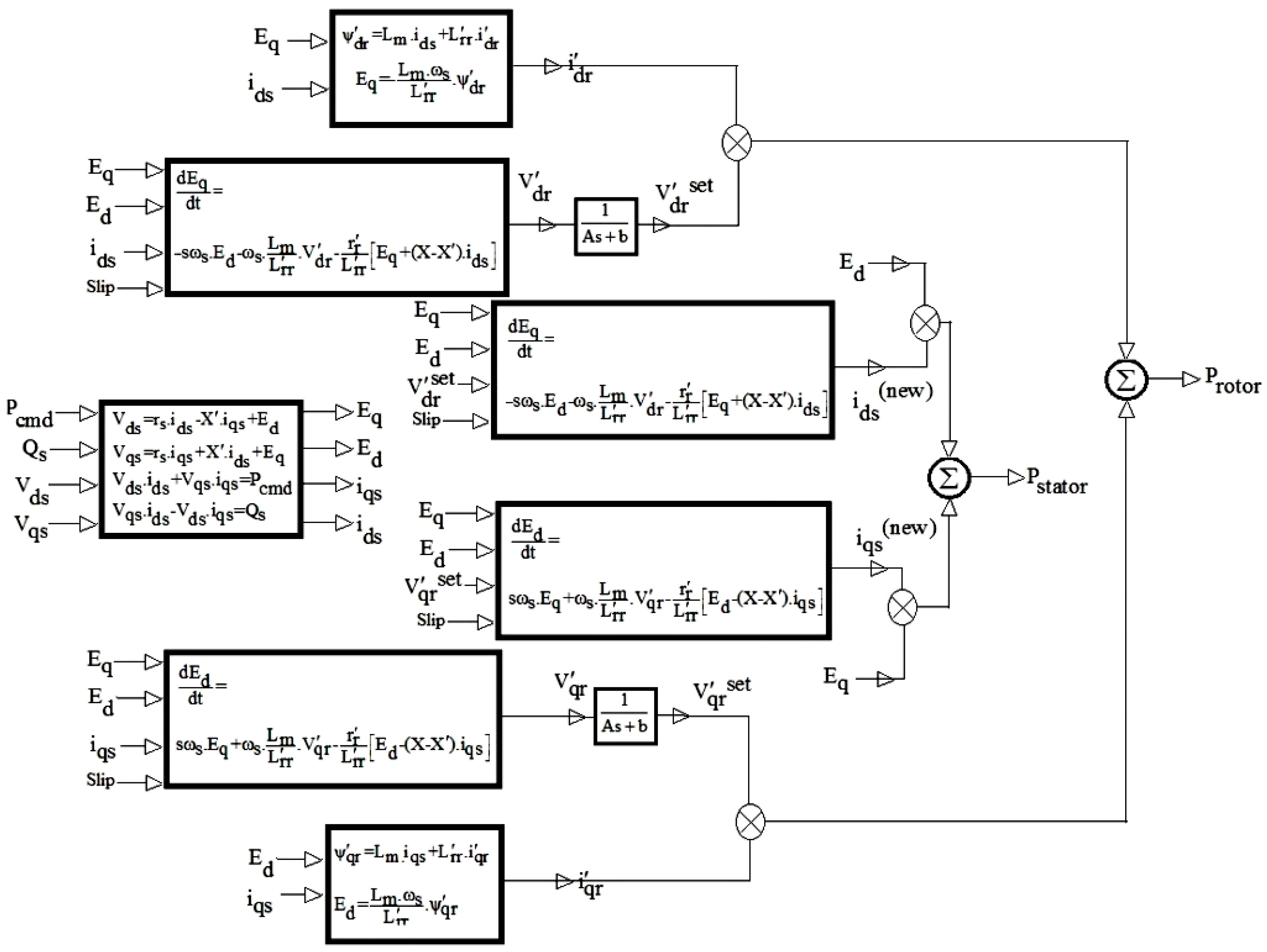
2. Transient Model of a Doubly Fed Induction Generator (DFIG)

In order to study the control strategies for frequency stability, a detailed model of DFIG has been extracted. The proposed model can be divided into electrical and mechanical parts. The electrical part model describes the procedure in which the electrical output power of DFIG is generated according to its set point values dictated by WF control unit. The mechanical part model describes how the torque and speed of the WTG are controlled, according to the control strategy, so that the WTG can participate in the system’s frequency control.

2.1. Electrical Part

Rotor voltage is not zero and hence, the dynamics related to the rotor circuit are considered in the model. Input signals to the model are Pcmd, reactive power command set point ( Q s ), direct and quadrature components of stator terminal voltage, V ds and V qs respectively. Equations (1)–(4) relate the parameters mentioned below to the input signals [21,22].
V ds =   r s i ds X i qs +   E d ,
V qs =   r s i qs + X i ds +   E q ,
V ds i ds +   V qs i qs =   P cmd ,
V qs i ds V ds i qs =   Q s ,
X   =   ω s ( L ss L m 2 L rr ) ,
r s is the stator winding resistance. i ds and i qs are direct and quadrature components of stator current respectively. L m , L ss are magnetizing inductance and stator winding inductance. In order to express the voltage equations in machine, all rotor variables are referred to the stator windings by appropriate turns ratios. L rr is the rotor winding inductance referred to stator windings. X is the transient reactance value calculated by Equation (5). ψ qr and ψ dr , quadrature and direct components of rotor flux linkages per second referred to the stator windings, are calculated applying Equations (6) and (7).
ψ qr   =   L m i qs + L rr i qr ,
ψ dr =   L m i ds + L rr i dr ,
i dr and i qr are direct and quadrature components of rotor current, referred to the stator windings. By expressing the rotor flux linkages per second in terms of E d and E q , the voltages behind the transient reactance, dynamic Equations (8) and (9) can be obtained [2].
dE q dt   =   s ω s E d ω s L m L rr V dr r r L rr [ E q   +   ( X X ) i ds ] ,
dE d dt   =   s ω s E q +   ω s L m L rr V qr r r L rr [ E d ( X X ) i qs ] ,
E d   = L m ω s L rr ψ qr ,
E q = L m ω s L rr ψ dr ,
V dr and V qr are direct and quadrature components of rotor voltage, referred to the stator windings. In order to model the time delay related to the control procedure, a transfer function has been considered in the proposed electrical model in Figure 1. Parameters A and b are set to 0.5 s and 1, respectively [2]. The outputs are V dr ( set ) and V qr ( set ) . Finally, by substituting the values of V dr ( set ) and V qr ( set ) in Equations (8) and (9), the updated values of i ds ( new ) and i qs ( new ) can be obtained. By eliminating the stator resistance losses, stator electromagnetic power can be approximated by Equation (12):
P s =   E d i ds ( new )   +   E q i qs ( new ) ,
In addition, the rotor output power can be calculated by Equation (13):
P r = V dr ( set ) i dr + V qr ( set ) i qr ,
The total real output power of DFIG injected into the power system is equal to the sum of values obtained from Equations (12) and (13), neglecting power losses in the converters. Figure 1 demonstrates electrical part model of DFIG with related equations.

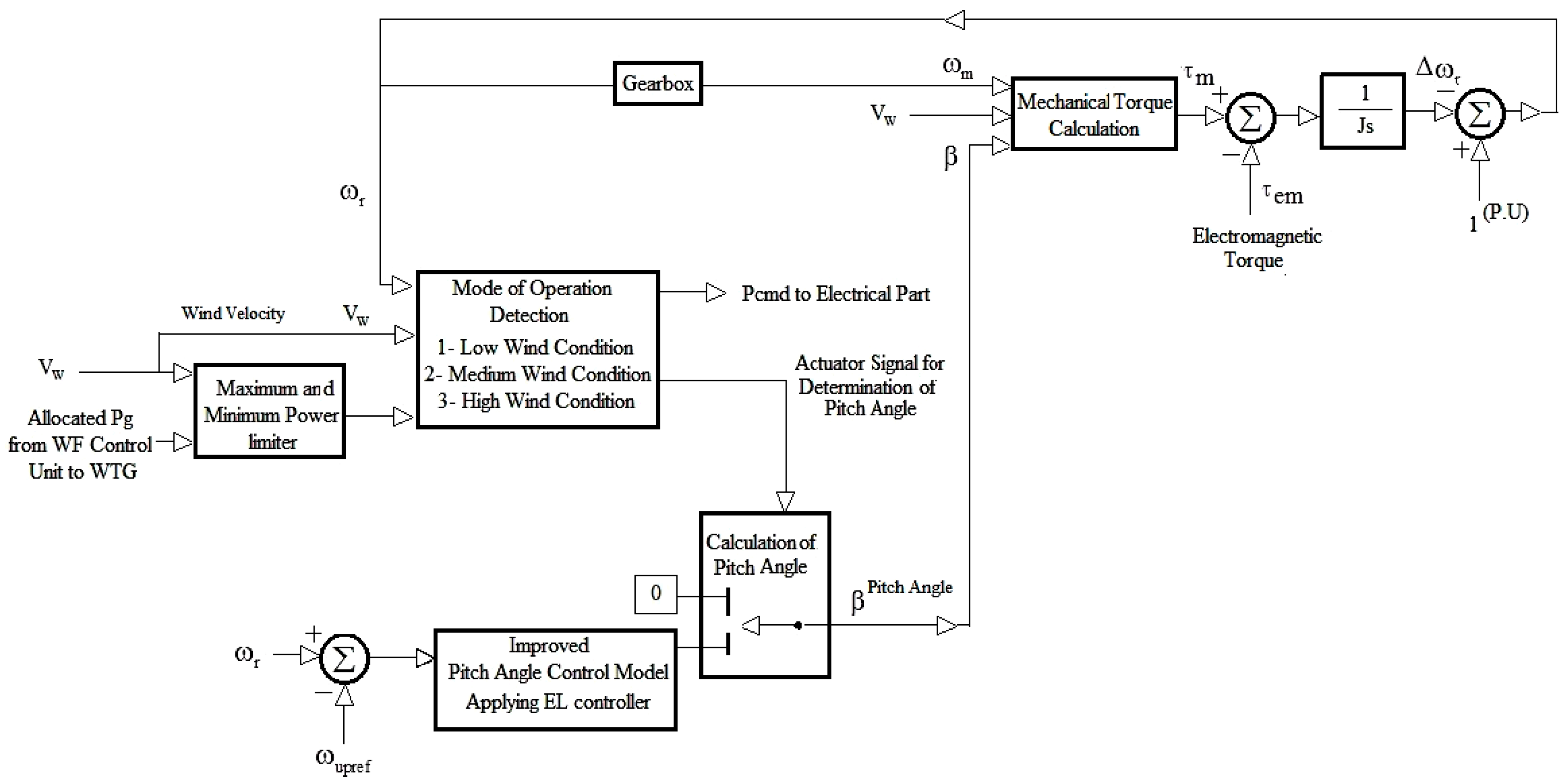
2.2. Mechanical Part

A schematic of the extracted model of the DFIG mechanical part is shown in Figure 2.
The model includes a series combination of turbine controller and induction generator controller. Pcmd is applied to the individual wind turbine controller from WF control unit. WF control unit receives its set point from AGC unit in the power system.
Considering the available wind power, wind turbine rotor speed and the proposed control strategy in the decision-making unit, Pcmd and a set point for wind turbine blade pitch angle are determined. Pcmd is applied to the electrical part and the set point for blade pitch angle is sent to the pitch angle controller. All of the described procedure is intended to trace the determined output power by WF control unit. The mechanical torque in the wind turbine shaft is calculated applying Equation (14).
τ m ω m = 1 2 C p ( β , λ ) ρ AV w 3 ,
C p is the power coefficient of the wind turbine, ρ is the air density, A (m2) is the cross section of the WTG aerodynamic rotor, V w is the wind velocity (m/s), and ω m is the wind turbine rotor speed. In C p , β is the pitch angle of the turbine and λ is the tip speed ratio. Tip speed ratio can be calculated applying Equation (15).
λ   = R ω m V w ,
where R (m) is the blade radius. C p is calculated applying Equation (16) [21].
C p ( β , λ )   = 1 2 ( RC f λ 0.022 β 2 ) e 0.255 RC f λ ,
C f is the blade design constant. The electromagnetic torque ( τ em ) produced by electrical part, according to the applied Pcmd, will then react to the mechanical torque ( τ m ) by the swing equation mentioned in Equation (17).
τ m τ em =   J d ω r dt ,

3. Control Strategy

The proposed control strategy can be explained in two levels. The first level is related to the active power control of a DFIG according to its set point dictated by WF control unit. The second level is related to set point allocation to individual WTGs gathered together in a WF.

3.1. Active Power Control of a DFIG

Initially, a Pcmd is sent to the DFIG from WF control unit. Regarding WTG rotor speed feedback and the available wind velocity, Pcmd is corrected and applied to the electrical part model as mentioned in Section 2. If Pcmd is not appropriately allocated to each individual WTG, stability problems may occur.
Considering all possible situations in this procedure, three modes of operation can be defined as follows:
• Medium wind condition
In this mode of operation, when wind velocity fluctuates, the moment of inertia in WTG acts to absorb or release energy. As rotor speed varies between allowable operating limits, DFIG traces the Pcmd properly and keeps the WTG output constant. Changes in the value of Pcmd and τ em will result in a new state of ω r .
• High wind condition
There are situations in which Pcmd is not properly set and this makes the DFIG accelerate and rotor speed may run out of its upper limit. If preventive action is not taken, stability problems may occur [23]. When this situation takes place, wind acquisition must be limited by initializing pitch angle controller. When ω r is near its upper limit ( ω up . lim ), the total wind power acquisition must be reduced by proper adjustment of turbine’s blade pitch angle. The schematic of the proposed PAC is depicted in Figure 3. The difference between ω r and its upper reference ( ω r max ) is applied to a proportional controller and then to a servomotor to adjust the pitch angle. A proper speed margin between ω r max and ω up . lim must be considered to ensure proper operation of pitch angle control unit. When ω r decreases, WTG operation switches back to the mode of medium wind condition.
• Low wind condition
There are situations in which the available wind power is lower than the Pcmd set point value determined by WF control unit, which results in ω r reduction. In order to maintain stable performance of DFIG, Pcmd must be corrected in this case applying Equation (18) [4].
P cmd ( new ) =   Pcmd   +   P slope ( ω r ω 0 ) ,
P cmd ( new ) is the corrected value of Pcmd. ω 0 is the rotor speed corresponding to the value of Pcmd. P slope is calculated according to Equation (19). P start and ω start are cut-in power and rotor speed, respectively.
P slope   =   P 0 P start ω 0 ω start ,

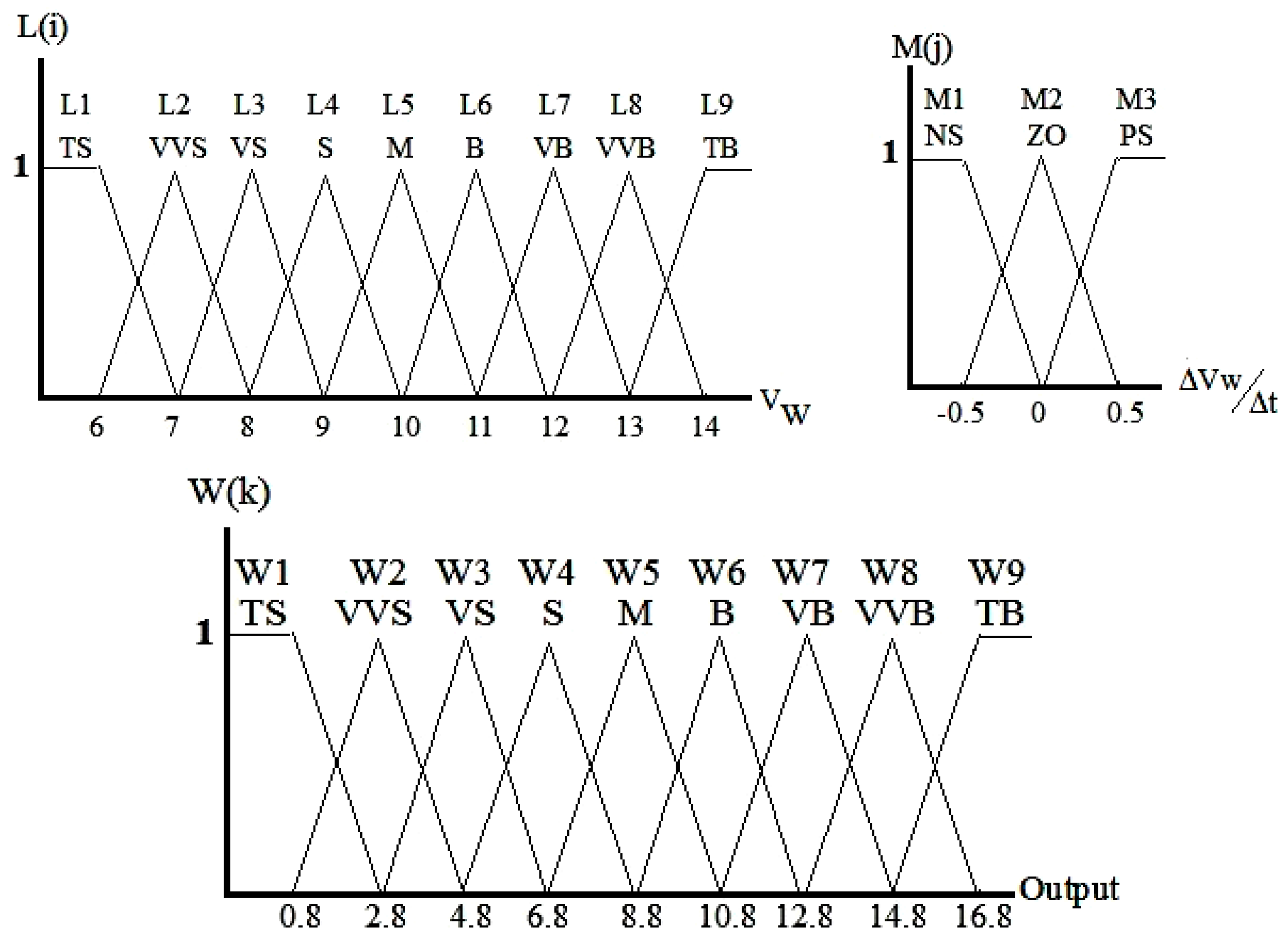
3.2. Fuzzy Logic Controller

In order to allocate proper Pcmds to individual WTGs, FLC has been applied [24]. Regarding the command of AGC unit to WF control unit, proper Pcmds must be formed for the WTGs in the WF. Generally, the higher the WTG’s available wind velocity is, the higher the available power is according to Equation (14). Therefore, the Pcmd value must be weighted higher for the WTG with high available wind power. In this procedure, FLC helps in mitigation of sudden changes in the allocated Pcmd to individual WTGs. Thus, less stress is put on frequency stability of the system. In this paper, the membership functions of FLC are in the form of triangular functions. The nth fuzzy rule is expressed in Equation (20). The values of the counters n, i, j and k are set just for the case study in this paper.
Rule nth : if V w is L ( i ) and Δ V w Δ t is M ( j ) , then Output is W ( k ) n = 1 , 2 , , 27 i = 1 , 2 , , 9 j = 1 , 2 , 3 k = 1 , 2 , , 9 ,
One input of the FLC is the current state of wind velocity with membership function L ( i ) and the other input is the rate of the changes of wind velocity with membership function M ( j ) . The output is the weighting factor for individual WTGs in the WF with membership function W ( k ) . Figure 4 demonstrates the membership functions of the proposed fuzzy weighting approach.
Table 1 shows fuzzy reasoning procedure in the proposed FLC.

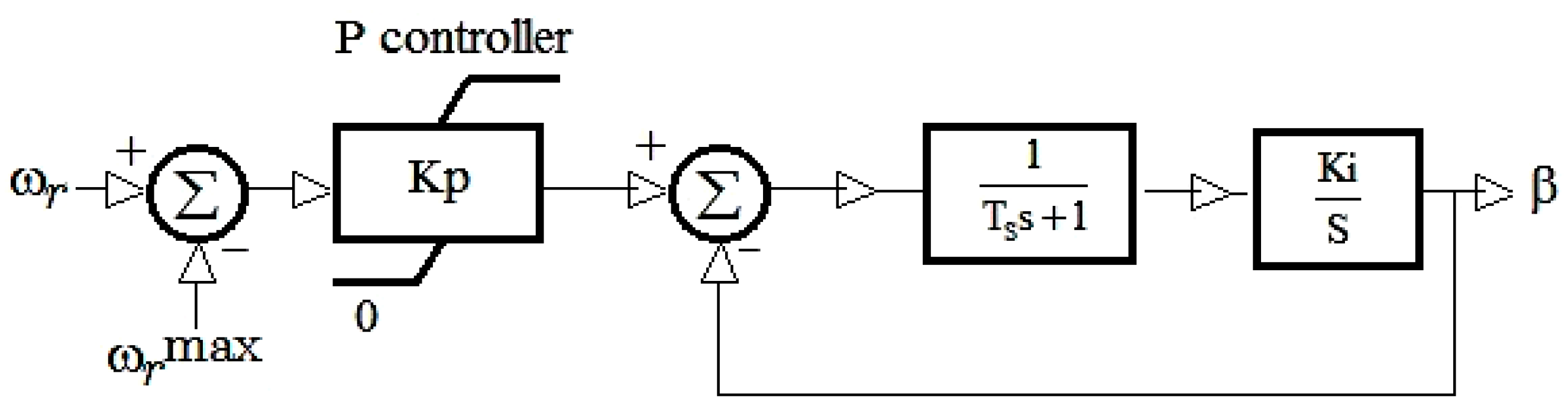
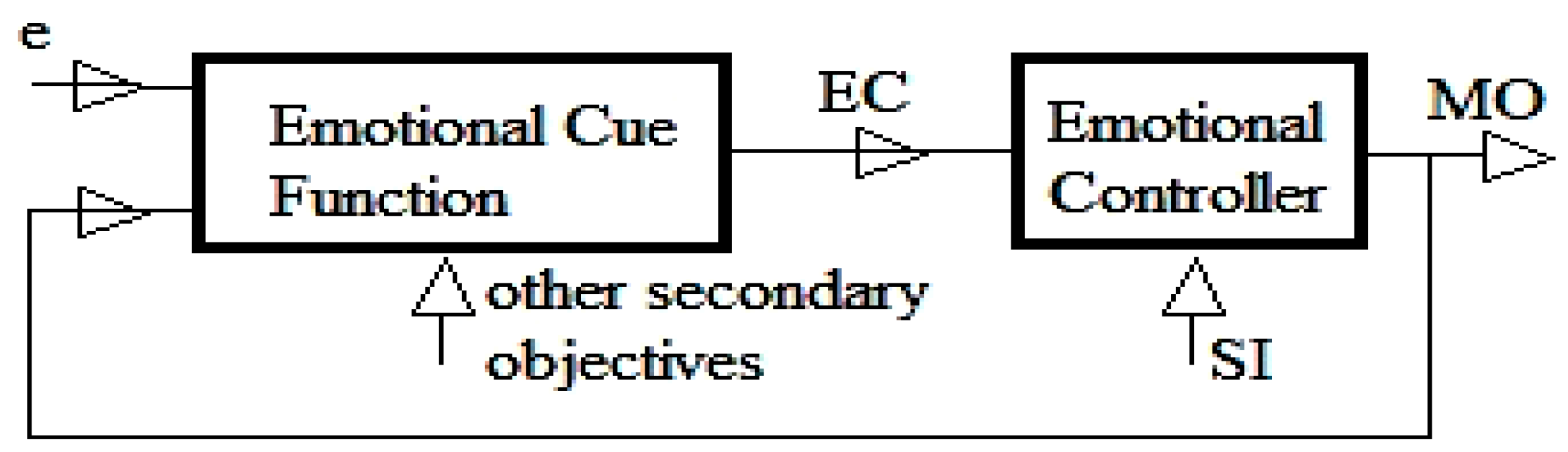
3.3. Emotional Learning Based Intelligent Controller

In this paper, in order to set proper values for the coefficient of PAC in the mechanical part model of wind turbine, an intelligent control strategy based on human brain mechanisms of emotional learning (EL) has been applied. Figure 5 demonstrates the schematic of the proposed intelligent controller.
The computational model consists of amygdala and orbitofrontal Cortex units. Amygdala has the task of emotional assessment of stimuli. Orbitofrontal cortex plays the role of correcting the responses and adverse reactions of amygdala. Based on theories, these two units perform the EL [25,26]. Computational model output (MO) is calculated applying Equation (21).
MO   =   AO OCO ,
AO and OCO represent amygdala and Orbitofrontal outputs respectively and can be calculated applying Equations (22) and (23). G a and G oc are gains of amygdala and orbitofrontal units, respectively [27].
AO   =   G a SI ,
OCO   =   G oc SI ,
The input stimulation signal (SI) is calculated applying Equation (24) where signal e is considered the difference between the WTG rotor speed and its upper limit in the mode of applying PAC during high wind condition.
SI   =   K p e   +   K i 0 t edt ,
EC stands for emotional signal, which indicates the desirability of the controller performance, and is composed of signal e and MO with their appropriate weighting factors, a ec 1 and a ec 2 , respectively. EC is calculated applying Equation (25).
EC   =   a ec 1 e   +   a ec 2 MO ,
The learning law is mentioned in Equations (26) and (27). K1 and K2 are learning rates in amygdala and orbitofrontal units, respectively.
Δ G a =   k 1 max ( 0 , EC AO ) 0 ,
Δ G oc =   k 2 ( MO EC ) ,
Totally, the output of the model, MO in the Equation (21), can be rewritten as Equation (28).
MO   =   ( G a G oc ) SI G ( SI , EC , ) SI ,
If the gains of amygdala and orbitofrontal units are set properly, EL based intelligent controller helps in achieving a proper value for the proportional gain of PAC in each individual WTG and thus, the output power will trace the Pcmd with the least oscillations in the frequency during wind oscillations. This results in better frequency stability of the system.

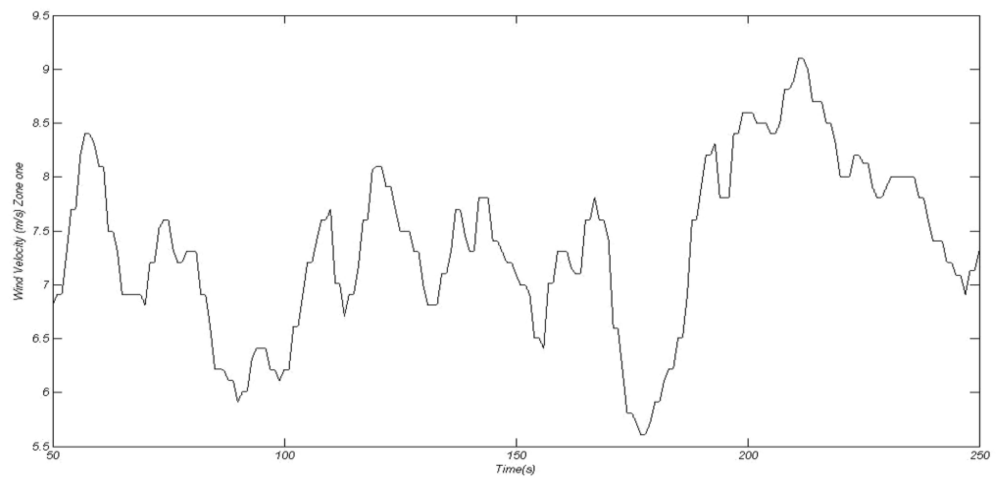
4. Geographical Dispersion of Wind Velocities in Wind Farm (WF)

As a small deviation in the wind velocity estimation can cause large consequences on the frequency of the system, the effect of geographical dispersion of wind velocity in a WF must be taken into account. In an actual wind site, wind velocity observed at a meteorological station with specific geographic coordinates must be adjusted for WTGs presented in that site. Wind velocity changes with the height above the ground and with the type of terrain surfaces. The logarithmic wind profile, mentioned in Equation (29), is a good approximation for these variations [28].
V 2   =   V 1 ln h 2 z 2 ln h 1 z 1 ,
V1 is the reference wind velocity at the reference height h1, V2 is the wind velocity at height h2. Z1 and Z2 are roughness lengths at the reference point and the considered point, respectively. Z varies between 0.0002 to 1.6 m. Detailed specification of parameter Z, mentioned in Equation (29), has been mentioned in Table 2. It must be noted that the considered range of parameter Z covers all land types on which WFs can be constructed [29].

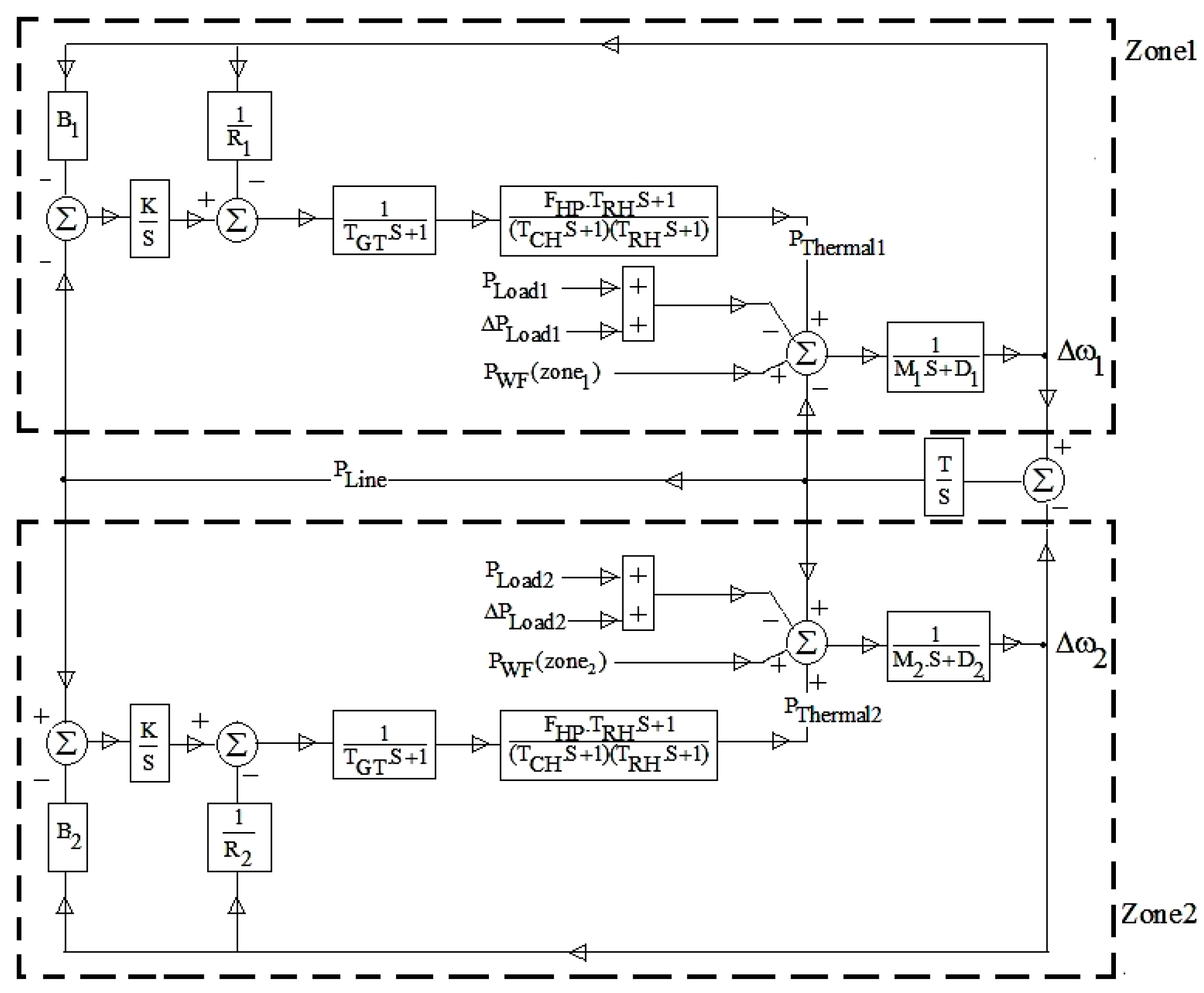
5. Contribution of Wind Power in Frequency Control

In order to investigate the effectiveness of the proposed control strategies in frequency control of a system with high percentage of wind power penetration, a simulated test system containing two zones connected to each other via a tie line is considered. Each zone consists of a conventional thermal plant and a WF, supplying local load demand. Today, there exist power systems in which the percentage of wind power in supplying the total load demand is quite high. Also, with growing global demand for more green energy, and advances in wind technology, it is conceivable that wind penetration levels in power systems can grow even higher. Hence, an appropriate test system must be considered to give a close estimation of developing power systems with high percentage of wind power penetration. For this purpose, in the considered power system, 30% of the total load is supplied by WTGs and the other 70% is supplied by conventional units. Under these conditions, a proper simulation of the whole power system can be achieved. The capacity of each thermal unit is 20 MVA and each WTG capacity is 2 MW. In addition, load demand variations are considered to be supplied by WTGs. The model of the thermal plants is based on the proposed model in [9]. The values of the thermal units’ parameters in the model are shown in Table 3.
In this paper, WTGs with the capacity of 2 MW have been employed in the simulations. The values of the WTGs’ parameters in the model are shown in Table 4 [30].
Figure 6 demonstrates the simulated scheme of the test system, which is composed of two zones. Each zone consists of a thermal unit with an interconnected WF supplying a local load demand. Two considered zones have been connected to each other via a tie line.
It has been assumed that each zone consists of 4 WTGs as representatives of an individual WF. In order to perform a realistic modeling, different geographical zones have been considered for WTGs’ locations in two WFs. In the simulations, WF1 roughness length varies between 0.03 and 0.055. WF2 roughness length varies between 0.1 and 0.2. In order to compare different frequency control scenarios and the proposed control strategy described in this paper, simulations have been conducted on the test system and the results are reported here. Three control strategies are studied as follows:
  • Using a lookup table to allocate weighting factors to individual WTGs in two simulated WFs.
  • Using FLC to allocate weighting factors to individual WTGs in two simulated WFs.
  • Applying EL controller to set the best value of proportional controller in pitch angle controller and FLC to allocate weighting factors to individual WTGs in each of the two simulated WFs.

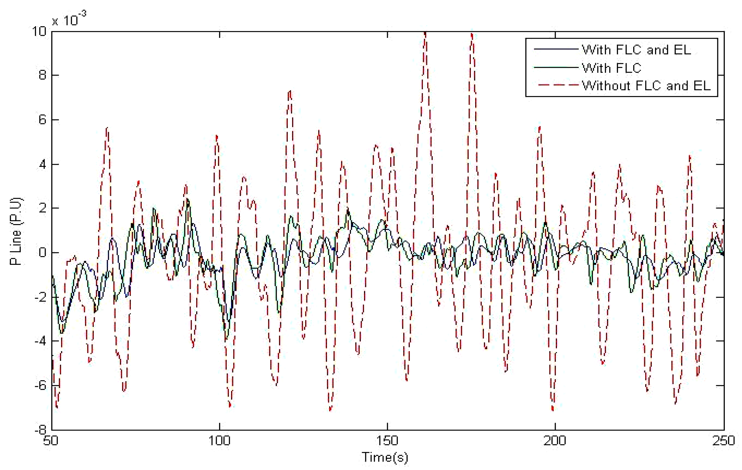
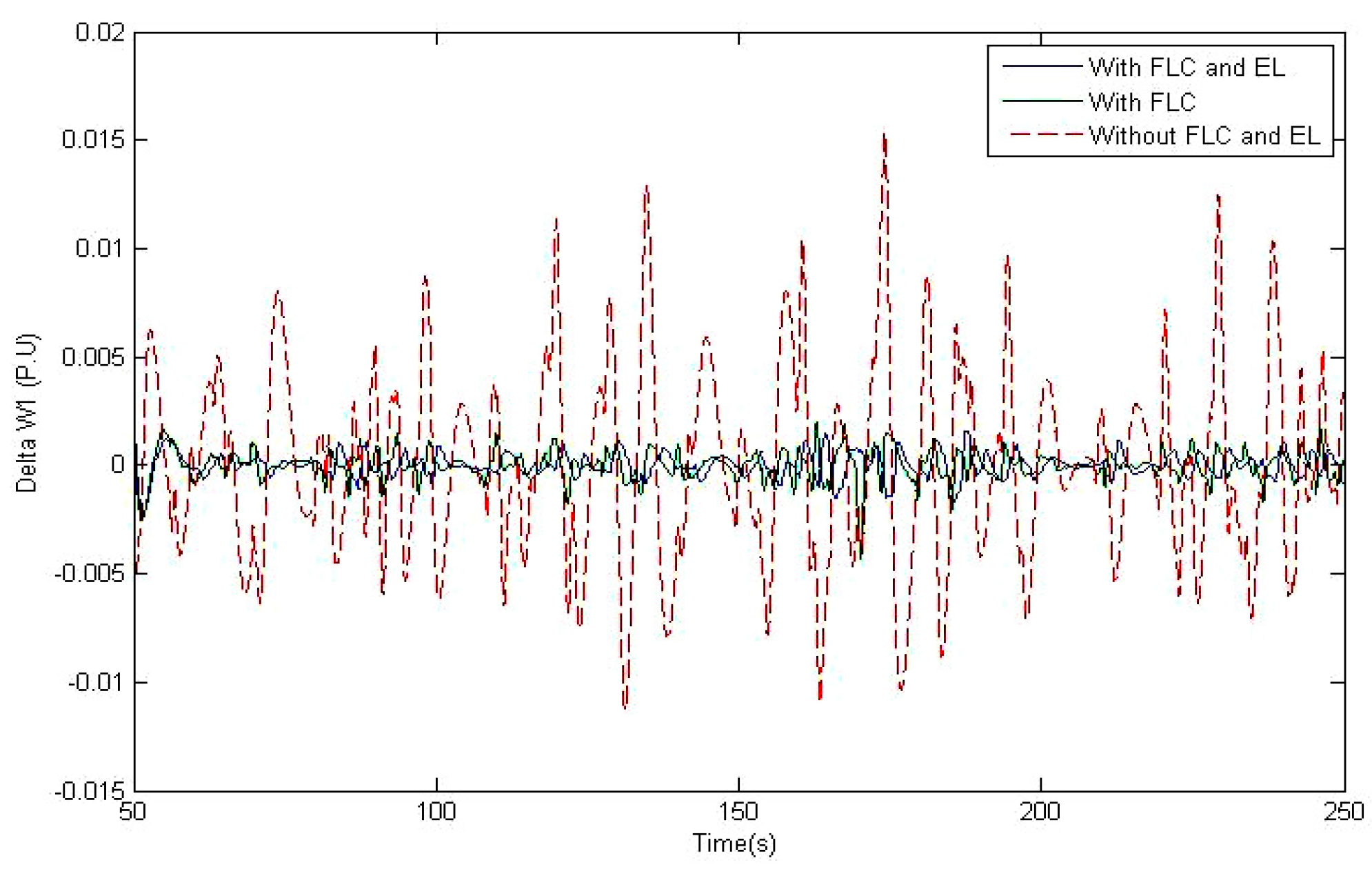
6. Simulation Results and Discussions

Wind regimes applied to each of the two WFs in the simulations are depicted in Figure 7 and Figure 8 [31]. Different WTGs in a WF experience different wind regimes, depending on their location. Therefore, in the simulation procedure, wind regimes in Figure 7 and Figure 8 have been adjusted for each of the WTGs in the WF applying Equation (29).
In order to get a close estimation of the real power system on one hand, and applying extreme conditions to ensure good performance of the proposed control system on the other hand, it has been assumed that two sudden changes occur in load demand of two simulated zones in the proposed power system. Zone one experiences a sudden change of 0.01 P.U at 50th second and zone two experiences a sudden change of −0.01 P.U at 100th second in the simulations [32]. The line power transfer between the two zones, considering different control strategies, is demonstrated in Figure 9. As time passes and wind velocity varies, the transferred power between the two zones varies. It is obvious that the highest range of transferred power oscillations between the zones is in the case of applying lookup table control strategy to allocate set points to individual WTGs. By applying just FLC in allocating WTGs’ set points, the domain of oscillations is decreased. Finally, applying dual control strategies, FLC and EL, decreased the oscillations to a maximum of 0.004 P.U.
Figure 10 demonstrates the output power of conventional thermal plant in zone one. It can be noted that the power oscillation in the output power of this plant is the least in the case of applying dual control FLC and EL. Without the FLC and EL, wide range of the oscillations my result in frequency stability problems.
The output power of the thermal plant in zone two is depicted in Figure 11. In this case, similar to the previous case, power oscillation is the least in the case of applying dual control FLC and EL.
Frequency deviations from the base value of 1 P.U in two zones are depicted in Figure 12 and Figure 13. It is noted that in the case of applying a lookup table to allocate best set points to individual WTGs, great deviations in frequency occurs and this may result in frequency instability. Applying FLC decreases these oscillations, but the best result among these three solutions is achieved in the case of applying FLC and EL controller.

7. Conclusions

Recently, with high penetration of WTGs in the power system, WTGs are participating in frequency control of the system. As wind varies with time, suitable frequency control solutions must be applied to reach the goal of frequency stability in the power system. In this paper, a completed model of DFIG, both in electrical and mechanical parts, for dynamic studies in frequency stability analysis is proposed. A control strategy to regulate Pcmd for individual WTGs in a WF is introduced which is based on the available wind power. The proper set points are allocated to WTGs according to their weighting factors determined by FLC. In addition to the proposed solution, an emotional learning based intelligent controller has been applied in determination of proper coefficients of DFIGs’ output power controller. This results in proper tracing of Pcmd by the DFIGs in the times of wind velocity variations. Simulation results performed on a test system consisting of both conventional units and WTGs, validates the effectiveness of the proposed control strategy in comparison with other mentioned solutions. Among the solutions mentioned in this paper, simultaneous application of the proposed controlling strategies results in the best condition of frequency stability in the test system. However, it must be borne in mind that for utility power industry, power distribution stability is very critical. Therefore, any actual implementation of the proposed schemes in a power system may require further study to ensure maximum possible power distribution stability.

Author Contributions

The first author has undertaken the current research as part of his Ph.D. thesis. The second and the third authors have acted as the thesis supervisor and advisor for the first author, respectively.

Conflicts of Interest

The authors declare no conflict of interest.

References

  1. Kanna, O.; Hanba, S.; Asato, S.; Yamashita, K. A Method of Stabilization of a Wind Generator Power Using Back Stepping Algorithm. IEEJ Trans. Power Energy 1997, 117, 1513–1519. [Google Scholar] [CrossRef]
  2. Lei, Y.; Mullane, A.; Lightbody, G.; Yacamini, R. Modeling of the wind turbine with a doubly fed induction generator for grid integration studies. IEEE Trans. Energy Convers. 2006, 21, 257–264. [Google Scholar] [CrossRef]
  3. Steban, M.D.; Diez, J.J.; Lopez, J.S.; Negro, V. Why offshore wind energy? Renew. Energy 2011, 36, 444–450. [Google Scholar] [CrossRef] [Green Version]
  4. Chang-Chien, L.R.; Lin, W.T.; Yin, Y.C. Enhancing Frequency Response Control by DFIGs in the High Wind Penetrated Power Systems. IEEE Trans. Power Syst. 2011, 26, 710–718. [Google Scholar] [CrossRef]
  5. Ackermann, T.; Abbad, J.R.; Dudurych, I.M.; Erlich, I.; Holttinen, H.; Kristofferson, J.R.; Sorensen, P.E. European Balancing Act. IEEE Power Energy Mag. 2007, 5, 90–103. [Google Scholar] [CrossRef]
  6. Chang-Chien, L.R.; Hung, C.M.; Yin, Y.C. Dynamic Reserve Allocation for System Contingency by DFIG Wind Farms. IEEE Trans. Power Syst. 2008, 23, 729–736. [Google Scholar] [CrossRef]
  7. Chang-Chien, L.R.; Yin, Y.-C. Strategies for Operating Wind Power in a Similar Manner of Conventional Power Plant. IEEE Trans. Energy Convers. 2009, 24, 926–934. [Google Scholar] [CrossRef]
  8. Wood, A.J.; Wollenberg, B.F. Control of Generation. In Power Generation, Operation and Control, 2nd ed.; John Wiley and Sons: New York, NY, USA, 2013; pp. 345–360. ISBN 978-0-471-79055-6. [Google Scholar]
  9. Kundur, P. Control of Active Power and Reactive Power. In Power System Stability and Control; Balu, N.J., Lauby, M.G., Eds.; McGrawHill: New York, NY, USA, 1994; pp. 581–627. ISBN 978-0070359581. [Google Scholar]
  10. Rodriguez, J.M.; Fernandez, J.L.; Beato, D.; Iturbe, R.; Usaola, J.; Ledesma, P.; Wilhelmi, J.R. Incidence on Power System Dynamics of High Penetration of Fixed Speed and Doubly Fed Wind Energy Systems: Study of the Spanish Case. IEEE Trans. Power Syst. 2002, 4, 1089–1095. [Google Scholar] [CrossRef]
  11. Rueda, J.L.; Erlich, I. Impacts of large scale integration of wind power on power system small signal stability. In Proceedings of the First International Conference on Electric Utility Deregulation and Restructuring and Power Technologies, Weihai, China, 6–9 July 2011; pp. 673–681. [Google Scholar]
  12. Slootweg, J.G.; Polinder, H.; Kling, W.L. Representing wind turbine electrical generating systems in fundamental frequency simulations. IEEE Trans. Energy Convers. 2003, 18, 516–524. [Google Scholar] [CrossRef]
  13. Slootweg, J.G.; Kling, W.L. The impact of large scale wind power generation on power system oscillations. Electr. Power Syst. Res. 2003, 67, 9–20. [Google Scholar] [CrossRef]
  14. Neris, A.; Vovos, N.; Giannakopaulos, G. A variable speed wind energy conversion scheme for connection to weak ac systems. IEEE Trans. Energy Convers. 1999, 14, 122–127. [Google Scholar] [CrossRef]
  15. Akhmatov, A. Analysis of Dynamic Behavior of Electric Power Systems with Large Amount of Wind Power. Ph.D. Thesis, Technical University of Denmark, Lyngby, Denmark, 2003. [Google Scholar]
  16. ESB National Grid, Grid Code. Available online: http://www.eirgrid.com (accessed on 20 June 2017).
  17. Xue, Y.; Tai, N. Review of contribution to frequency control through variable speed wind turbine. Renew. Energy 2011, 36, 1671–1677. [Google Scholar] [CrossRef]
  18. Teninge, A.; Jecu, C.; Roye, D.; Bacha, S.; Duval, J.; Belhomme, R. Contribution to frequency control through wind turbine inertial energy storage. IET Renew. Power Gener. 2009, 3, 358–370. [Google Scholar] [CrossRef]
  19. Zhao, H.; Wu, Q.; Hu, S.; Xu, H.; Nygaard Rasmussen, C. Review of energy storage system for wind power integration support. Appl. Energy 2015, 137, 545–553. [Google Scholar] [CrossRef]
  20. De Almeida, R.G.; Pecas Lopes, J.A. Participation of doubly fed induction wind generators in system frequency regulation. IEEE Trans. Power Syst. 2007, 22, 944–950. [Google Scholar] [CrossRef]
  21. De Almeida, R.G.; Pecas Lopes, J.A.; Barreiros, J.A.L. Improving Power System Dynamic Behavior Through Doubly Fed Induction Machines Controlled by Static Converter Using Fuzzy Control. IEEE Trans. Power Syst. 2004, 19, 1942–1950. [Google Scholar] [CrossRef]
  22. Krause, P.C.; Wasynczuk, O. Symmetrical Induction Machines. In Analysis of Electric Machinery and Drive Systems, 2nd ed.; Akay, M., Anderson, J.B., Eds.; John Wiley and Sons: New York, NY, USA, 2002; pp. 141–181. ISBN 0-471-14326-X. [Google Scholar]
  23. Luo, C.; Banakar, H.; Baike, S.; Ooi, B. Strategies to smooth wind power fluctuations of wind turbine generator. IEEE Trans. Energy Convers. 2007, 22, 341–349. [Google Scholar] [CrossRef]
  24. Lee, C.C. Fuzzy logic in control systems: Fuzzy logic controller. IEEE Trans. Syst. 1990, 20, 404–418. [Google Scholar] [CrossRef]
  25. Moren, J.; Balkenius, C. A Computational Model of Emotional Learning in the Amygdala. In From Animals to Animats 6: Proceedings of the 6th International Conference on the Simulation of Adaptive Behavior, Cambridge; MIT Press: Cambridge, MA, USA, 2000; pp. 115–124. [Google Scholar]
  26. Fatourechi, M.; Lucas, C.; Khaki Sedigh, A. Reduction of Maximum Overshoot by means of Emotional Learning. In Proceedings of the 6th Annual CSI Computer Conference, Isfahan, Iran, 20–22 February 2001; pp. 460–467. [Google Scholar]
  27. Huang, G.; Zhen, Z.; Wang, D. Brain Emotional Learning Based Intelligent Controller for Nonlinear System. In Proceedings of the Second International Symposium on Intelligent Information Technology Application, Shanghai, China, 20–22 December 2008; pp. 660–663. [Google Scholar]
  28. Coelingh, J.P. Geographical Dispersion of Wind Power Output in Ireland; IWEA Irish Wind Energy Association: Kildare, Ireland, 1999; pp. 4–9. [Google Scholar]
  29. Wind Profile Calculator Considering Roughness Classes and Lengths. Available online: http://wind-data.ch (accessed on 1 July 2017).
  30. Wen, Z.W.; Ding, L.; He, S. Analysis on Effect of Parameters of Different Wind Generator on Power Grid Transient Stability. Energy Power Eng. 2013, 5, 363–367. [Google Scholar] [CrossRef]
  31. Wind Group Association. Wind Velocity Database of Binalood Wind Farm; Sun-Air Research Institute of Ferdwosi University: Mashhad, Iran, 2016. [Google Scholar]
  32. Tripathy, S.C.; Kalantar, M.; Balasubramanian, R. Dynamics and Stability of Wind and Diesel Turbine Generators with Superconducting Magnetic Energy Storage Unit on an Isolated Power System. IEEE Trans. Energy Convers. 1991, 6, 579–585. [Google Scholar] [CrossRef]
Figure 1. The electrical part model of doubly fed induction generator (DFIG).
Applsci 07 01140 g001
Figure 2. The mechanical part model of DFIG with controlling procedure.
Applsci 07 01140 g002
Figure 3. Schematic of pitch angle control (PAC).
Applsci 07 01140 g003
Figure 4. Membership functions for fuzzy weighting approach.
Applsci 07 01140 g004
Figure 5. Emotional learning (EL) process trend. Adapted from [25].
Applsci 07 01140 g005
Figure 6. The proposed test system.
Applsci 07 01140 g006
Figure 7. Wind regime applied to zone one.
Applsci 07 01140 g007
Figure 8. Wind regime applied to zone two.
Applsci 07 01140 g008
Figure 9. Transferred power between the two zones.
Applsci 07 01140 g009
Figure 10. The output power of thermal unit in zone one.
Applsci 07 01140 g010
Figure 11. The output power of thermal unit in zone two.
Applsci 07 01140 g011
Figure 12. Frequency deviations of zone one.
Applsci 07 01140 g012
Figure 13. Frequency deviations of zone two.
Applsci 07 01140 g013
Table 1. Fuzzy rules for fuzzy weighting approach.
Fuzzy Reasoning Δ V w / Δ t
NSZOPS
V w TSTSTSVVS
VVSTSVVSVS
VSVVSVSS
SVSSM
MSMB
BMBVB
VBBVBVVB
VVBVBVVBTB
TBVVBTBTB
NS = Negative Small; ZO = Zero; PS = Positive Small; TS = Too Small; VVS = Very Very Small; VS = Very Small; S = Small; M = Medium; B = Big; VB = Very Big; VVB = Very Very Big; TB = Too Big.
Table 2. Different roughness lengths and their land cover types. Data from [29].
Roughness Length ZLand Cover Types
0.0002 mWater surfaces: seas and Lakes
0.0024 mOpen terrain with smooth surface, e.g., concrete, airport runways, mown grass etc.
0.03 mOpen agricultural land without fences and hedges; maybe some far apart buildings and very gentle hills
0.055 mAgricultural land with a few buildings and 8 m high hedges seperated by more than 1 km
0.1 mAgricultural land with a few buildings and 8 m high hedges seperated by approx. 500 m
0.2 mAgricultural land with many trees, bushes and plants, or 8 m high hedges seperated by approx. 250 m
0.4 mTowns, villages, agricultural land with many or high hedges, forests and uneven terrain
0.6 mLarge towns with high buildings
1.6 mLarge cities with high buildings and skyscrapers
Table 3. Value of parameters in thermal units’ model. Data from [9].
ParameterValueParameterValue
FHP0.3M1, M25
TRH7 sD1, D21
TCH0.3 sk0.3
TGT0.2R10.05
T0.5B120.6
Table 4. Value of parameters in wind turbine generators’ (WTGs’) model.
ParameterValueParameterValue
Prated2 MWXm3.5 P.U
Lss3.6 P.Urs0.0043 P.U
L’rr3.78 P.Ur’r0.012 P.U
Cf0.7 P.UR50 m

