Theoretical Analysis for the Flow Ripple of a Tandem Crescent Pump with Index Angles

State Key Laboratory of Fluid Power and Mechatronic Systems, Zhejiang University, Hangzhou 310027, China
*
Author to whom correspondence should be addressed.
Appl. Sci. 2017, 7(11), 1148; https://doi.org/10.3390/app7111148
Submission received: 16 October 2017
/
Revised: 31 October 2017
/
Accepted: 3 November 2017
/
Published: 8 November 2017
(This article belongs to the Special Issue Power Transmission and Control in Power and Vehicle Machineries)
Abstract
:Featured Application
This paper presents a theoretical approach for lowering the outlet flow ripple of a crescent pump by applying a tandem crescent pump consisting of two gear pairs with an index angle between them.
Abstract
This paper presents a theoretical approach for lowering the outlet flow ripple of a crescent pump by applying a tandem crescent pump consisting of two gear pairs with an index angle between them. The outlet flow of the tandem pump is obtained by summing the flow produced by the two gear pairs, and the flow ripple of the tandem pump can be attenuated by properly selecting the design parameters in terms of the index angle and the displacement ratio between the two gear pairs. A lumped parameter model is presented for evaluating the crescent pump’s flow ripples, and experiments were performed on a single crescent pump to validate the model from the aspects of the steady-state flow-pressure characteristics and the outlet pressure ripples. In this way, the main causes of the flow ripple could be identified by comparing the kinematic flow with the actual flow evaluated by the model. Additionally, simulation results suggested that a tandem pump with an index angle of 13.85° and displacement ratio of 0.5 could lead to a more than 45% decrease in the outlet flow ripple than a single pump with the same displacement in a wide range of operating conditions.
1. Introduction
Crescent pumps are widely used in many fluid power applications such as injection molding machines, automotive applications, and robotic systems due to their advantages in terms of compactness, low flow ripple, and low noise level [1,2,3]. Today, with the increase in demand for injection quality and control accuracy, it is hoped that the flow ripple of the crescent pump can be reduced [4]. This paper focused on a theoretical approach for lowering the flow ripple by applying a tandem crescent pump comprised of two sets of gear pairs with an index angle between them.
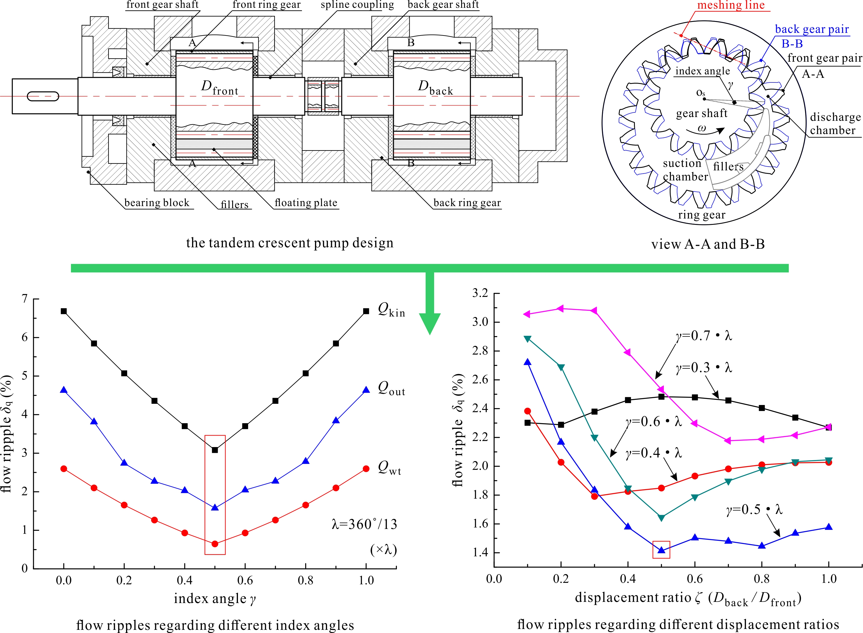
Figure 1 depicts a schematic of the tandem crescent pump with two sets of indexed gear pairs. As suggested by the name, the tandem pump is composed of two gear pairs, namely the front gear pair and the back gear pair, and each gear pair can fulfill the function of fluid delivery via meshing as typical crescent pumps. Figure 1 also illustrates the basic working principle of the crescent pump (displacement pump): sealing chambers are formed by the floating plates, the crescent fillers, and the gear pair (the gear shaft and the ring gear), and by meshing the gears, fluid is sucked into the suction chamber due to the increase of the suction chamber’s volume, delivered to the discharge chamber, and then discharged from the discharge chamber due to the decrease of the discharge chamber’s volume.
As shown in Figure 1, the back gear shaft is connected to the front gear shaft via a spline coupling, which enables the same angular velocity and an index angle between the two gear shafts (view A-A and B-B). It should be noted that the flowrate by the two gear pairs can be varied by setting different widths of the gear pairs (parameter ‘b’), and a design parameter, namely, the displacement ratio is introduced, which is defined as the ratio of the displacement by the back gear pair to that by the front gear pair. By sharing the same inlet and outlet, the outlet flow of the tandem pump is obtained by superposing the flow produced by the two gear pairs, and it is expected that the outlet flow ripple of the tandem pump can be attenuated by properly selecting the index angle and the displacement ratio.
Usually, the internal gear pumps (IGPs) are classified into two types based on the existence of the crescent fillers: the gerotor pumps without fillers and the crescent pumps with fillers, and the flow characteristics has represented a main focus in previous studies. After a thorough review of the literature, it was found that most publications concerning IGPs were related to gerotor pumps, with only a small number focused on crescent pumps. With respect to the gerotor pumps, Mimmi et al. [5,6] addressed the theoretical flow characteristics from a kinematic aspect (based on the theory of gearing), focusing on the influence of the gears’ geometric parameters. Gamez-Montero et al. [7,8] investigated the flow ripple characteristics via a mathematical model by means of the bond graph technique, and experimentally validated the model by measuring the instantaneous flow using the ‘secondary source’ method. Additionally, the same research group in Reference [9] further studied the flow ripple via a 3D computational fluid dynamics (CFD) model by means of ANSYS Fluent, allowing the analysis of the influence of the interteeth clearance and teeth contact for a better estimation of the instantaneous flow. Hsieh [10,11] built a CFD model for the gerotor pump using Pumplinks, presenting a novel geometrical design that enabled variable clearance between the inner and outer rotors for the purpose of lowering the flow ripples. Manco et al. [12] and Schweiger et al. [13] studied the flow ripple and the pressure ripple via a lumped parameter model by means of LMS Amesim, experimentally validating the model by measuring the steady-state flowrate and the outlet pressure ripples. In the work of Manco et al. [12], they suggested that a bi-rotor pump with indexed rotors had the potential to attenuate the flow ripple. Pellegri et al. [14,15] conducted a comparison between the lumped parameter and the CFD approach for a unique insight into the pump’s performance (volumetric efficiency, flow and pressure ripples, etc.), with a specific focus on the rotors’ radial micro-motions.
With respect to the crescent pumps, Ichikawa [16] addressed the mathematical expressions for the ideal delivery from a kinematic aspect, focusing on the variations of the trapped volume. Zhou et al. [17] studied the theoretical flow characteristics based on the theory of gearing, and presented a set of conjugated involute gears that enabled better fluid delivery capacity. Additionally, the same research group in Reference [18] extended the study to the trapped volume performances via a discretization approach, with a specific focus on the gears’ geometric parameters. Rundo [19] investigated the theoretical flowrate of the crescent pumps with respect to different combinations of the gear pair’s tooth numbers (the gear shaft and the ring gear), suggesting that the increase of the gear shaft’s tooth number helped attenuate the flow ripple. Moreover, the same research group in Reference [20] extended their research to cover the internal leakage and the outlet pressure ripple via a lumped parameter model built in LMS Amesim, validating the model through a comparison to experimental results on the steady-state flowrate and the outlet pressure ripples. Hence, it can be seen that few attempts have been made to study the flow ripple with respect to the tandem crescent pump design.
Concerning the tandem pump design, it has been previously applied in other hydraulic pumps, particularly in axial piston pumps and in external gear pumps. Manring et al. [21,22] addressed the theoretical torque ripple and flow ripple of a tandem axial piston pump with two identical rotating groups under different index angles from a kinematic aspect, suggesting that an index angle of 10° resulted in the greatest reduction of the flow ripple (roughly 75%) with respect to a nine-piston rotating group. Xu et al. [23] studied the tandem piston pump’s flow ripple via a lumped parameter model using LMS Amesim, suggesting that an index angle of 20° resulted in the greatest reduction of the flow ripple. In Xu et al.’s work, they suggest that the reason for the difference in index angle from that in Manring et al.’s work was due to the flow through the triangular grooves on the valve plate, which has been shown to have a great influence on the flow ripple (which was not considered in the work of Manring et al.). Battarra et al. [24] presented a tandem external gear pump comprised of a set of spur gears and a set of helical gears, sharing the same driving and driven shafts. However, the presented tandem external gear pump did not share the same outlet, thus the flow produced by the two gear pairs was delivered to two different hydraulic systems, which is different to the aforementioned tandem axial piston pump and the tandem crescent pump presented in this work.
Hence, few published works can be found on tandem crescent pump design. This paper focused on the flow ripple of the tandem crescent pump via a lumped parameter model built in Matlab. It was expected that the tandem crescent pump could lead to a decrease in the flow ripple through the proper selection of the design parameters in terms of the index angle and the displacement ratio. The rest of the paper is organized as follows: the simulation model is proposed in Section 2 focusing on the evaluations of the flow and pressure in the sealing chambers around the gear circumference; the validation of the model is conducted in Section 3 from the aspects of the steady-state flowrate and the outlet pressure ripples; the numerical results are presented in Section 4 regarding the pump’s outlet flow and the related flow ripples; and discussions and conclusions are made in Section 5 based on the numerical results.
2. Simulation Model
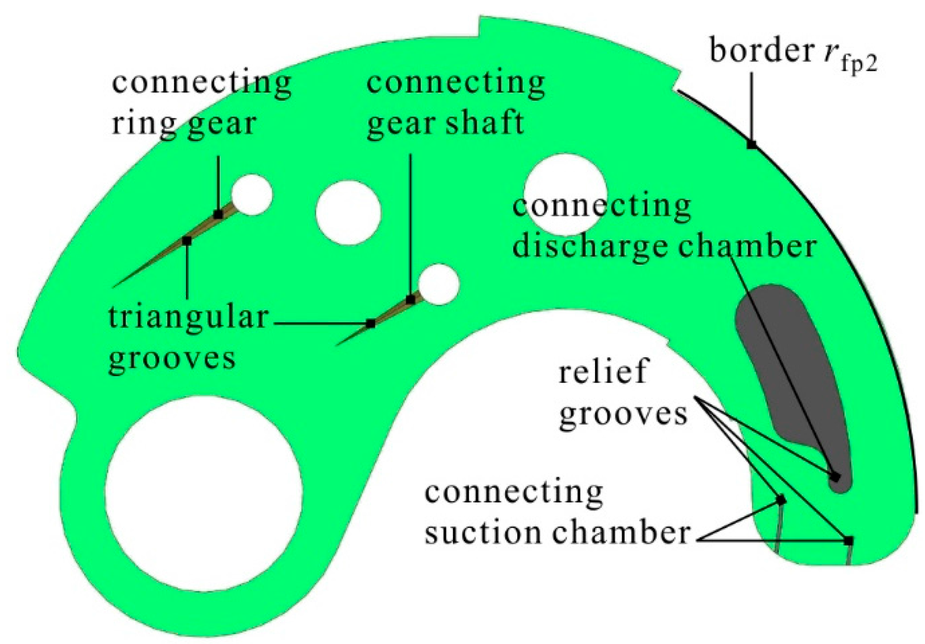
Figure 2 depicts the sealing chambers around the gear circumference divided by the meshing gears and the crescent fillers: the suction chamber, the transitional chamber, the discharge chamber and the trapped chamber (if it exists), where the suction chamber is formed by the gear profiles between the meshing point C2 and the intersections A1 and A2; the transitional chamber denotes the tooth space (TS) located in the transitional stage from the suction chamber to the discharge chamber; the discharge chamber is formed by the gear profiles between the meshing point C1 and the intersections B1 and B2; and the trapped chamber is formed by the gear profiles between the two meshing points C1 and C2. Flow exchange was observed between the adjacent sealing chambers via the clearances and the grooves machined on the floating plate, namely the triangular grooves and the relief grooves, due to the pressure difference, as shown in Figure 3. To account for the flow characteristics, an evaluation of the pressure evolution around the gear circumference, where the pressure in suction chamber can be treated as the inlet pressure (atmospheric pressure) was needed; the pressure with respect to time in the other three chambers can be evaluated by applying the mass conservation equation.
In Equation (1), β denotes the bulk modulus of the fluid. It should be noted that in this work, the oil temperature was set as a constant value (40 °C); hence the oil bulk modulus β was dependent on the pressure, as addressed by Xu et al. [25]. Regarding the other terms, V denotes the chamber’s volume; qin and qout denote the flow into and out of the chamber, respectively; and dV/dt denotes the time derivative of the chamber’s volume.
By applying Equation (1) to each chamber, the pressure can be estimated after evaluations of the terms in the right hand side of Equation (1), and the related flow characteristics can be obtained. Details are described in the following sub-sections on the evaluations of the related terms and their implementation in Matlab.
2.1. The Discharge Chamber
Figure 4 depicts a simple hydraulic system for the estimation of the crescent pump’s flow-pressure characteristics, which is comprised of a throttle valve utilized as the pump’s load, and a delivery line with a constant diameter utilized as the connection between the pump’s outlet and the throttle valve. As observed, the pressure in the discharge chamber corresponds to the pump’s outlet pressure. Regarding Equation (1), the term V denotes the volume of the discharge chamber and the delivery line, the term qin denotes the flow into the discharge chamber from the trapped chamber (qtrap in Figure 2) via the relief groove on the floating plate that connects the discharge chamber and the trapped chamber (Figure 3). In this scenario, the term qin yields
where qtrap is the trapped flow; Arel is the flow area of the relief groove; ptrap is the trapped pressure; ρ is the oil density dependent on the pressure (the oil temperature was set as a constant and not taken into account in this work), as addressed by Ivantysyn et al. [26]; Cd is the discharge coefficient dependent on the flow velocity and is difficult to be determined. In this work, the value of Cd was set as 0.7 according to the study by Ma et al. [27].
Regarding the term qout, it denotes the flow out of the discharge chamber, which consists of three terms: the valve flow through the throttle valve in the hydraulic system (qout,1 in Figure 4), the triangular flow into the transitional chamber through the triangular grooves on the floating plate (Figure 3), and the internal leakage of the pump. The first part can be given as
where qval is the flow through the throttle valve; and Aval is the flow area of the throttle valve.
As Figure 3 shows, two triangular grooves are machined on the floating plate, therefore, the triangular flow is further split into two terms accordingly: the flow (qtri,s) into the gear shaft’s tooth space (TS) and the flow (qtri,r) into the ring gear’s TS. The term qtri,r is depicted in Figure 2, and can be given as
where Atri is the flow area of the triangular groove; and pi + 1 and pi are the fluid pressures in the adjacent tooth spaces.
Noting that the term qtri,s can be evaluated in the same way as Equation (4), the triangular flow yields
With respect to the internal leakage of the pump, it can be split into three terms according to different types of clearances inside the pump: the lateral leakage through the lateral clearances between the gears’ lateral sides and the floating plates, the radial leakage through the radial clearances between the gears’ tooth tips and the fillers, and the ring-gear/case leakage through the clearance between the ring gear and the case.
Figure 5 depicts the lateral leakage that goes through the gear shaft’s lateral side (ql,s) and the ring gear’s lateral side (ql,r), thus the lateral leakage is further split into two terms accordingly. As observed, due to the complexity of the gears’ profiles, the lateral leakage is evaluated utilizing the annular areas bounded by the gears’ pitch circles and the floating plate’s borders. Using these quantities, the lateral leakage through the ring gear’s side (ql,r) yields
where ψd,r is the central angle of the discharge chamber; δl is the lateral clearance between the gears’ lateral sides and the floating plates; pin is the inlet pressure; and μ denotes the dynamic viscosity of oil dependent on the pressure (the oil temperature was set as a constant and not taken into account in this work), as addressed by Ivantysyn et al. [26].
Noting that the term ql,s can be evaluated in the same way as Equation (6) and there exist two lateral sides of the gears, the lateral leakage yields
Concerning the radial leakage, it can also be split into two terms like the lateral leakage: the flow through the gear shaft’s tooth tip (qr,s), and the flow through the ring gear’s tooth tip (qr,r). The term qr,r is depicted in Figure 2, and can be given as
where b is the width of the gear; δr is the radial clearance between the gears’ tooth tips and the fillers; lr is the length of the tooth tip; ωr is the angular velocity of the ring gear; and ra2 is the addendum radius of the ring gear.
Noting that the term qr,s can be evaluated in the same way as Equation (8), the radial leakage yields
Figure 6a depicts the cross section of the case for the analysis of the ring-gear/case leakage. It can be seen that rectangular sealing areas formed in the ring-gear/case interface surrounding the high pressure outlets. Moreover, fluid film formed in the sealing areas for the purpose of sealing, bearing and lubricating, and there was leakage flow in the film due to the pressure difference between the outlets and the borders of the sealing areas. Noting the small ratio between the film height (micrometer level) and the other two dimensions (millimeter level), the sealing area was unwrapped on a plane, as shown in Figure 6b, and was treated as a rectangular hydrostatic bearing. In this scenario, the ring-gear/case leakage (qrc) through the rectangular sealing area can be evaluated with Equation (10) according to the study by Hamrock et al. [28].
where bB, bL1, bL2, B and L are the geometric parameters of the sealing area depicted in Figure 6b; and δ is the radial clearance between the ring gear and the case.
Hence, the internal leakage of the pump yields by summing all the leakages is
and the term qout in Equation (1) yields
Regarding the term dV/dt, it denotes the time derivative of the discharge chamber’s volume, which can be interpreted as the kinematic flow of the crescent pump derived from the kinematic relations according to the work by Zhou et al. [17].
where Vkin is the volume of the discharged fluid when the pump operates for a period of time t from the kinematic aspect; Qkin is the kinematic outlet flow; ω is the angular velocity of the gear shaft; ra1 and ra2 are the addendum radii of the gear shaft and the ring gear, respectively; rf1 and rf2 are the distances between the contact point and the centers of the gear shaft and the ring gear, respectively; and z1 and z2 are the tooth numbers of the gear shaft and the ring gear, respectively.
2.2. The Trapped Chamber
According to the theory of gearing, one or two meshing points are formed during the meshing process. Under the circumstance of two meshing points, a trapped chamber is formed by the gears’ profiles between the two meshing points, as shown in Figure 2. Regarding the terms in Equation (1), the term V denotes the trapped chamber’s volume, which is characterized first by a decrease, then followed by an increase; the term dV/dt denotes the variations of the trapped chamber’s volume, which can be evaluated as
As shown in Figure 2 and Figure 3, relief grooves are machined on the floating plate to connect the trapped chamber to the discharge chamber during the volume decreasing stage, and to the suction chamber during the volume increasing stage. Hence, the terms qin and qout are contributed by two types of flow: the flow through the relief grooves, which can be evaluated by Equation (2) (p = pout when connected to the discharge chamber, p = pin when connected to the suction chamber); and the lateral leakage, which can be evaluated by Equations (6) and (7).
2.3. The Transitional Chamber
As stated above, the transitional chamber denotes the gears’ TS located in the transitional stage, which can be divided into two categories: the gear shaft’s TS and the ring gear’s TS. As shown in Figure 2 and Figure 3, triangular grooves are machined on the floating plate to connect the transitional chamber to the discharge chamber, which enables flow into the transitional chamber due to the pressure difference between the discharge chamber and the transitional chamber for the purpose of increasing the fluid pressure in the transitional chamber from the inlet pressure to the outlet pressure smoothly. Hence, regarding the terms in Equation (1), the term V denotes the volume of the TS, the term dV/dt yields zero since the volume of the TS does not vary during the transitional stage, and the terms qin and qout are contributed by three types of flow: the flow through the triangular grooves, which can be evaluated by Equation (4); the lateral leakage, which can be evaluated by Equation (6); and the radial leakage, which can be evaluated by Equation (8).
2.4. Simulation Procedure
Figure 7 depicts the solution algorithm for the analysis of the tandem crescent pump’s flow characteristics implemented in Matlab. It starts with the input parameters of the pump’s geometric parameters and the initial values including the initial pressures in the sealing chambers and the initial oil properties, as shown in box 1. Concerning the tandem pump design, it was comprised of two sets of gear pairs characterized by two design parameters, namely the index angle (γ) and the displacement ratio (ζ), as shown in boxes 2 and 3 (in the blue dashed box).
The key part of the algorithm is represented by the evaluation of the outlet flow of one gear pair depicted in the red dashed box. With respect to a certain time step (the ith time step), the geometric features and the oil properties that vary over time need to be updated first, as shown in box 4: the key points (points A, B, C in Figure 2) for dividing the sealing chambers, the trapped chamber’s volume and its time derivative for the evaluation of the trapped pressure, the flow areas of the relief grooves and the triangular grooves on the floating plate for the evaluations of the trapped flow and the triangular flow, respectively, and the oil properties (ρ, β, μ), which are dependent on the pressure (boxes 4.1 to 4.4).
Under the circumstance of two meshing points (C1 and C2 in Figure 2, the trapped chamber exists), noting that the lateral leakage of the trapped chamber can be evaluated by Equations (6) and (7) (with different central angles), the trapped pressure in the next time step (the (i + 1)th time step) can be evaluated by applying the mass conservation equation written as Equation (15), as shown in box 5.
where Δt is the time interval between time steps.
The pressure in the transitional chamber in the (i + 1)th time step can be evaluated by Equation (16), the same way as that in the trapped chamber, noting that the term dV/dt yields zero and the leakage of the transitional chamber consists of two parts, namely the lateral leakage and the radial leakage, as shown in box 6.
where VTS is the volume of the tooth space; and ptran is the transitional pressure.
As stated above, the internal leakage of the pump consists of three parts: the lateral leakage and the radial leakage of the discharge chamber, and the ring-gear/case leakage, which can be evaluated by Equations (6) to (10) by leveraging the updated points B and C and the ith outlet pressure as shown in box 7. Noting that the time derivative of the discharge chamber’s volume is interpreted as the kinematic flow in Equation (13) (as shown in box 8), the outlet flow of one gear pair yields (box 9)
Hence, the outlet flow of the tandem pump yields by summing the flow produced by the two gear pairs (box 10).
Noting that the valve flow can be evaluated by Equation (3), the outlet pressure (pressure in the discharge chamber) in the (i + 1)th time step can be evaluated by Equation (19) as shown in box 12.
where Vd is the volume of the discharge chamber and the delivery line.
Hence, it can be seen that in the ith time step, the ith flow characteristics and the (i + 1)th pressures in the sealing chambers are evaluated; then in the (i + 1)th time step, the (i + 1)th pressures are used to evaluate the (i + 1)th flow characteristics and the (i + 2)th pressures until the end of a meshing period (boxes 13 and 14, loop1). At the end of the meshing period, the flow characteristics, in terms of the outlet flow, the triangular flow, the trapped flow, and the internal leakage, serve as the criteria to judge the convergence of the simulation, which is characterized by the fact that the flow characteristics do not differ from one meshing period to another defined by Equation (20); the simulation stops after the convergence of the simulation (boxes 15 and 16, loop2).
In Equation (20), qnew denotes the flow in the present meshing period; qold denotes the flow in the previous meshing period; and qerr denotes the error between the flow in the two successive meshing periods (converged to 10−8).
It is worthwhile to note that the time interval between time steps (Δt) was to the order of 10−8 s and the consuming time of the simulation process was roughly seven minutes with an Intel® Xeon® CPU E3-1230 v3 and 16.0 GB RAM.
3. Experimental Validation
Figure 8 depicts the test rig for the experimental campaign on a 40 cc/rev single crescent pump. It is worth noting that the layout of the test rig was in accordance with the hydraulic circuit displayed in Figure 4. As observed, the crescent pump was driven by a servo motor (0–2000 rpm), and its outlet pressure was built up by a throttle valve. The working medium of the pump was L-HM 46 mineral oil, and the oil temperature was maintained within (40 ± 3) °C, consistent with the oil temperature in the simulation model. The test rig enabled measurements of the steady-state outlet flowrate via a gear type flowmeter and the outlet pressure ripples via a high frequency pressure sensor. Table 1 provides the main features of the flowmeter and the pressure sensor which have been calibrated before experiments, and Table 2 provides the main geometric parameters of the crescent pump.
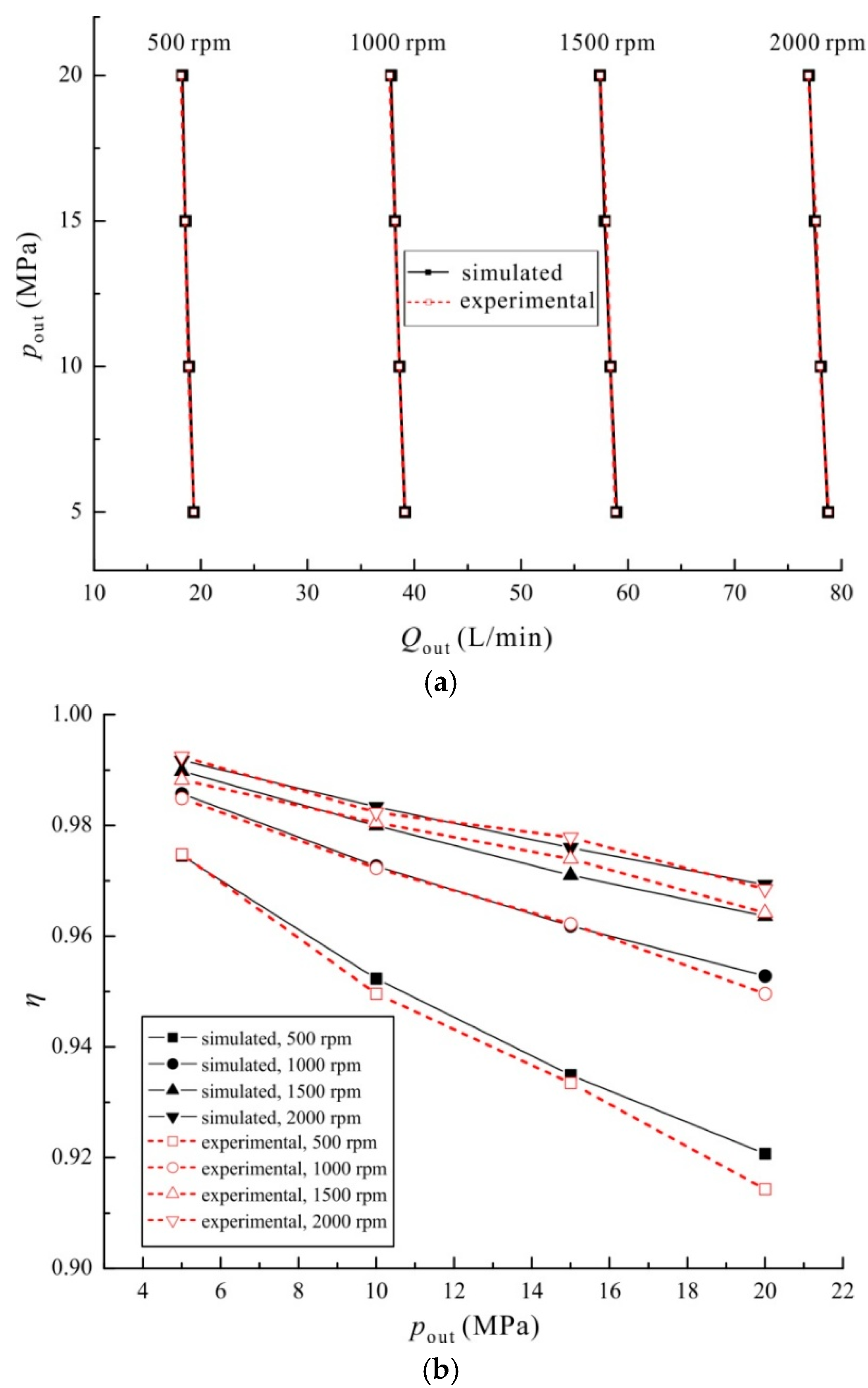
Figure 9 depicts the comparison between the simulated and experimental results concerning the steady-state flow characteristics with respect to different operating conditions (500–2000 rpm, 5–20 MPa). As observed, there existed a linear relationship between the flowrate and the operating speed, and the outlet flowrate yielded roughly 40 L/min at 1000 rpm, in accordance with the pump’s displacement (40 cc/rev). Furthermore, it was also observed that the outlet flowrate and the volumetric efficiency yielded a decrease as the outlet pressure increased (at a certain speed), which was expected since higher outlet pressure leads to greater internal leakage. A clear example can be given by the case of working at 500 rpm, where the volumetric efficiency drops from 0.98 at 5 MPa to 0.92 at 20 MPa. Moreover, it can be seen that a good agreement was found between the simulated and experimental results regarding the flowrate and the volumetric efficiency, noting that the accuracy of the flowmeter was within 0.3% (from measured value).
Figure 10 depicts the comparison between the simulated and experimental results on the outlet pressure ripples for one shaft revolution with respect to different operating conditions (500 rpm, 5 MPa; 500 rpm, 20 MPa; 2000 rpm, 20 MPa). As observed, 13 outlet pressure ripples existed in a shaft revolution, which is believed to be due to the tooth number of the gear shaft (driving gear) which was 13. Apart from that, it was visible that the pressure ripples yielded greater amplitudes under the circumstance of low operating speed and high outlet pressure (500 rpm, 20 MPa). Moreover, it can be seen that that a good agreement was found between the simulated outlet pressure ripples and the experimental results regarding different operating conditions, noting that the accuracy of the pressure sensor was within 0.5% (full scale) and the nonlinearity of the pressure sensor was within 0.5%.
Figure 11 depicts the comparison of the frequency spectra of the simulated and experimental outlet pressure ripples at 500 rpm, 20 MPa. As observed, the primary frequency concerning the simulated results yielded 108.33 Hz with an amplitude of 0.253 MPa, and the primary frequency concerning the experimental results yielded 108.33 Hz with an amplitude of 0.250 MPa, suggesting a good match of the frequency spectra. Aside from that, the primary frequency of the simulated and experimental results was in accordance with the analytical value given by Equation (21).
Judging from the analysis above, a good match was found between the simulated and experimental results regarding the steady-state outlet flowrate and the outlet pressure ripples, therefore justifying the capability of the proposed model regarding the analysis of the pump’s outlet flow characteristics.
4. Numerical Results
In this section, the numerical results from the simulation model will be presented in terms of the outlet flow of the tandem crescent pump, and the related flow ripples with respect to different design parameters and operating conditions.
4.1. Outlet Flow of the Crescent Pump
Figure 12 depicts the three types of outlet flow from one gear pair under 2000 rpm and 20 MPa: the kinematic outlet flow (Qkin) defined by Equation (13), the with-trapped outlet flow (Qwt) by taking the trapped flow into consideration defined by Equation (22), and the actual outlet flow (Qout) evaluated by the proposed model defined by Equation (23).
Referring to Figure 12, it can be seen that the three types of flow were subject to ripples with the period of approximately 27.7°, which was expected since the tooth number of the gear shaft (driving gear) was 13, as shown in Equation (24). The kinematic outlet flow (Qkin) yielded between 74.88 and 80.14 L/min; the with-trapped outlet flow (Qwt) yielded between 78 and 80.14 L/min; and the actual outlet flow (Qout) yielded between 75.25 and 78.33 L/min.
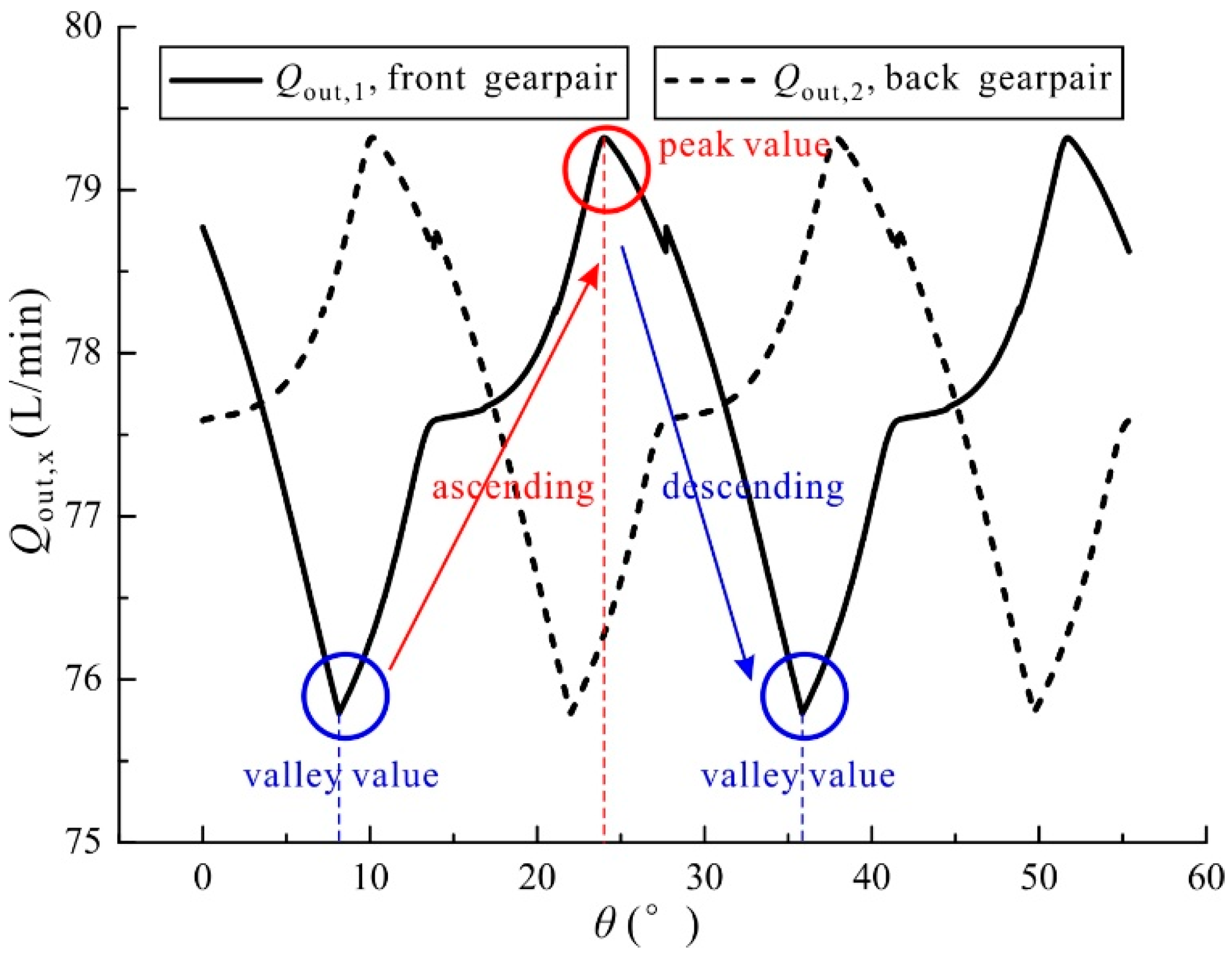
Figure 13 depicts the outlet flow from two gear pairs with an index angle (γ) under 2000 rpm and 20 MPa (ζ = 1). It can be seen that within a period, the flow from one gear pair was characterized by an ascending stage followed by a descending stage, and one could observe a peak value and a valley value. The flow from the two gear pairs were in the same shape since the displacement was ζ = 1. A phase difference was also observed between the flow from the two gear pairs due to the index angle.
Figure 14 depicts the outlet flow from the tandem pump (ζ = 1) under 2000 rpm and 20 MPa with respect to different index angles (0, λ/4, λ/2), noting that the index angle γ was bounded between 0 and λ. It can be seen that the outlet flow of the tandem pump exhibited a periodic behavior with the same period of 27.7° and roughly the same mean outlet flowrate though the index angle varied. However, the outlet flow exhibited different shapes and different ripples as the index angle varied. The outlet flow yielded between 151.59 and 158.64 L/min when γ = 0, between 153.25 and 156.96 L/min when γ = λ/4, and between 154.01 and 156.34 L/min when γ = λ/2.
Figure 15 depicts the outlet flow from the tandem pump (γ = λ/2) under 2000 rpm and 20 MPa with respect to different displacement ratios (0, 0.5, 1), noting that the displacement ratio ζ was bounded between 0 and 1. Expectedly, the outlet flow exhibits a periodic behavior with the period of 27.7°. It could also be seen that under the same operating conditions, the pump yielded different mean outlet flowrate and different flow ripples as the displacement ratio varied. The outlet flow yielded between 75.25 and 78.33 L/min when ζ = 0, between 115.02 and 116.88 L/min when ζ = 0.5, and between 153.91 and 156.34 L/min when ζ = 1.
4.2. Flow Ripple under Different Design Parameters
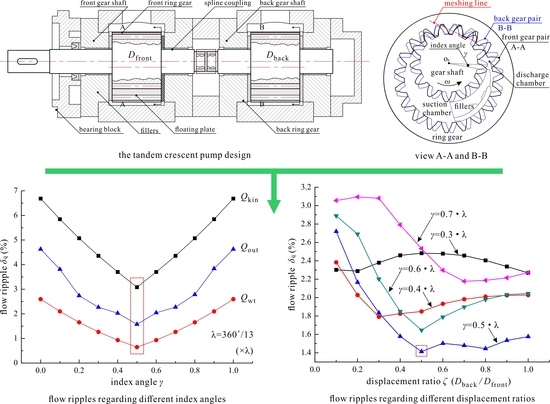
Figure 16 depicts the flow ripple (δq) of the tandem pump (ζ = 1) under 2000 rpm and 20 MPa regarding different index angles (from 0 to λ), noting that the flow ripple was defined by Equation (25), following the work addressed by Ivantysyn et al. [26].
where Qmax is the maximum flowrate; and Qmin is the minimum flowrate.
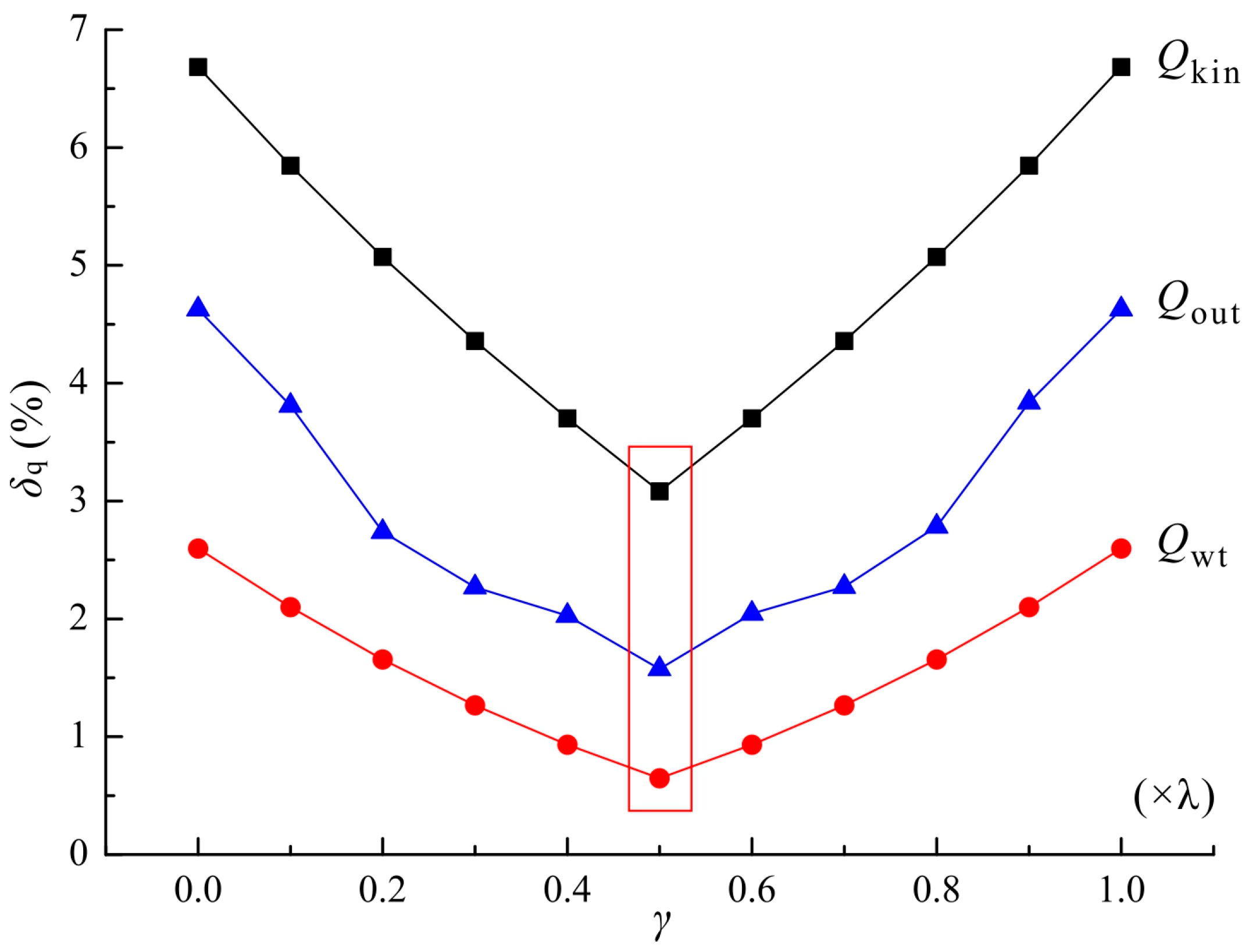
Referring to Figure 16, it was clear and consistent that with respect to a certain index angle, the tandem pump’s kinematic flow (Qkin) yielded a greater ripple while the with-trapped flow (Qwt) yielded a lower ripple than the actual flow (Qout). Additionally, as the index angle increased (from 0 to λ), one observed a decrease followed by an increase in the flow ripples of the three types of flow, and the flow obtained the minimum flow ripple when γ = λ/2 (in red rectangles). Concerning the actual flow (Qout), the maximum flow ripple was roughly 4.62% when γ = 0, and the minimum flow ripple was roughly 1.57% when γ = λ/2.
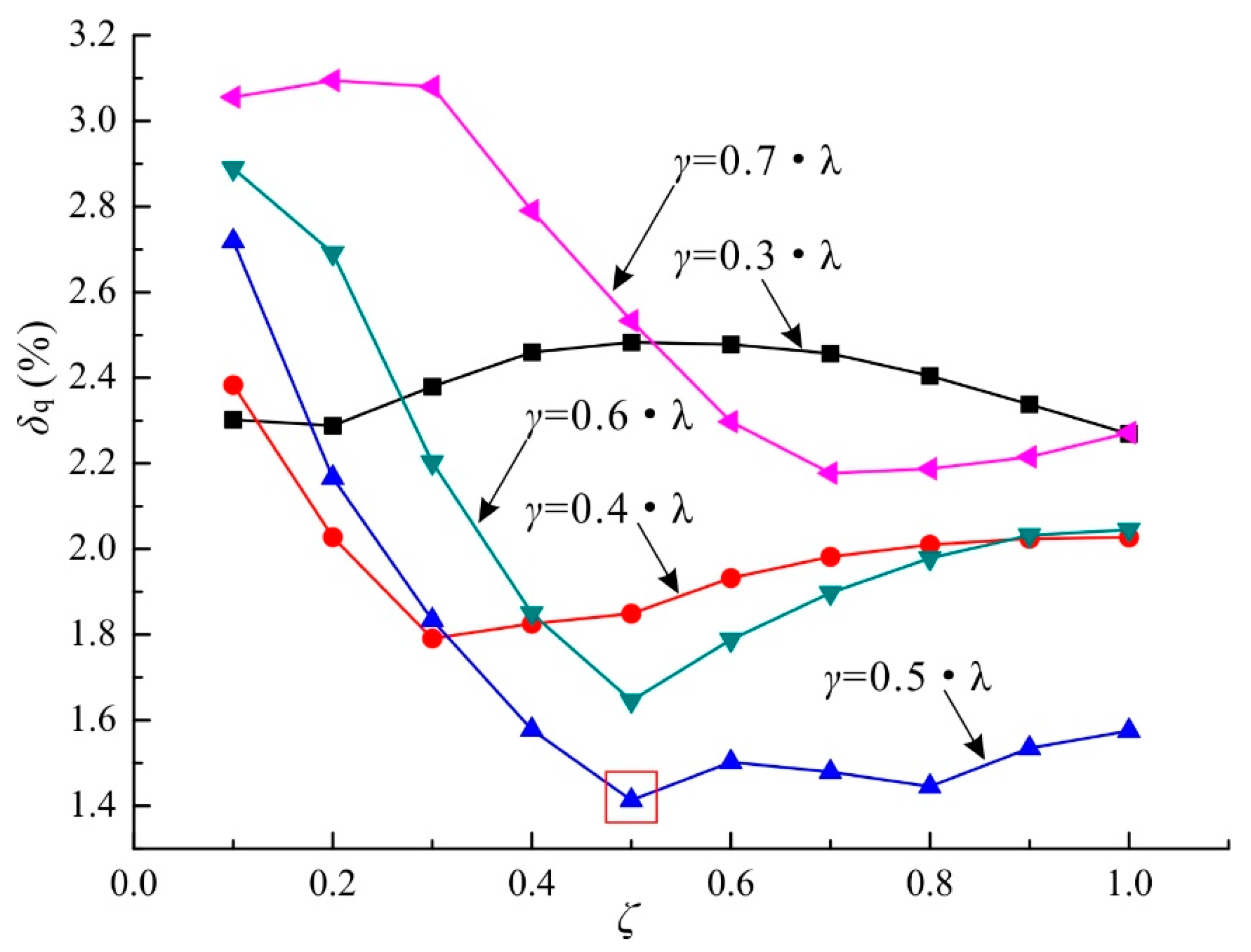
Figure 17 depicts the flow ripple of the tandem pump at 20 MPa regarding different displacement ratios (from 0.1 to 1) under the same mean outlet flowrate. The operating speed for the tandem pump with the displacement ratio ζ = 1 was 2000 rpm, and the operating speeds for other displacement ratios were set as Equation (26) for the purpose of maintaining the same mean outlet flowrate.
Referring to Figure 17, it can be seen that with respect to a certain index angle (γ), the flow ripple first exhibited a decrease, then followed by an increase as the displacement ratio (ζ) increased, and a minimum value of the flow ripple could be achieved by properly selecting the displacement ratio. With respect to a certain displacement ratio (ζ), the condition of γ = λ/2 yielded the minimum flow ripple when ζ was greater than 0.4. Hence, as observed, the condition of γ = λ/2 and ζ = 0.5 yielded the minimum flow ripple under the same outlet pressure and mean outlet flowrate (in red squares), and the related flow ripple yielded 1.41%.
4.3. Flow Ripple under Different Operating Conditions
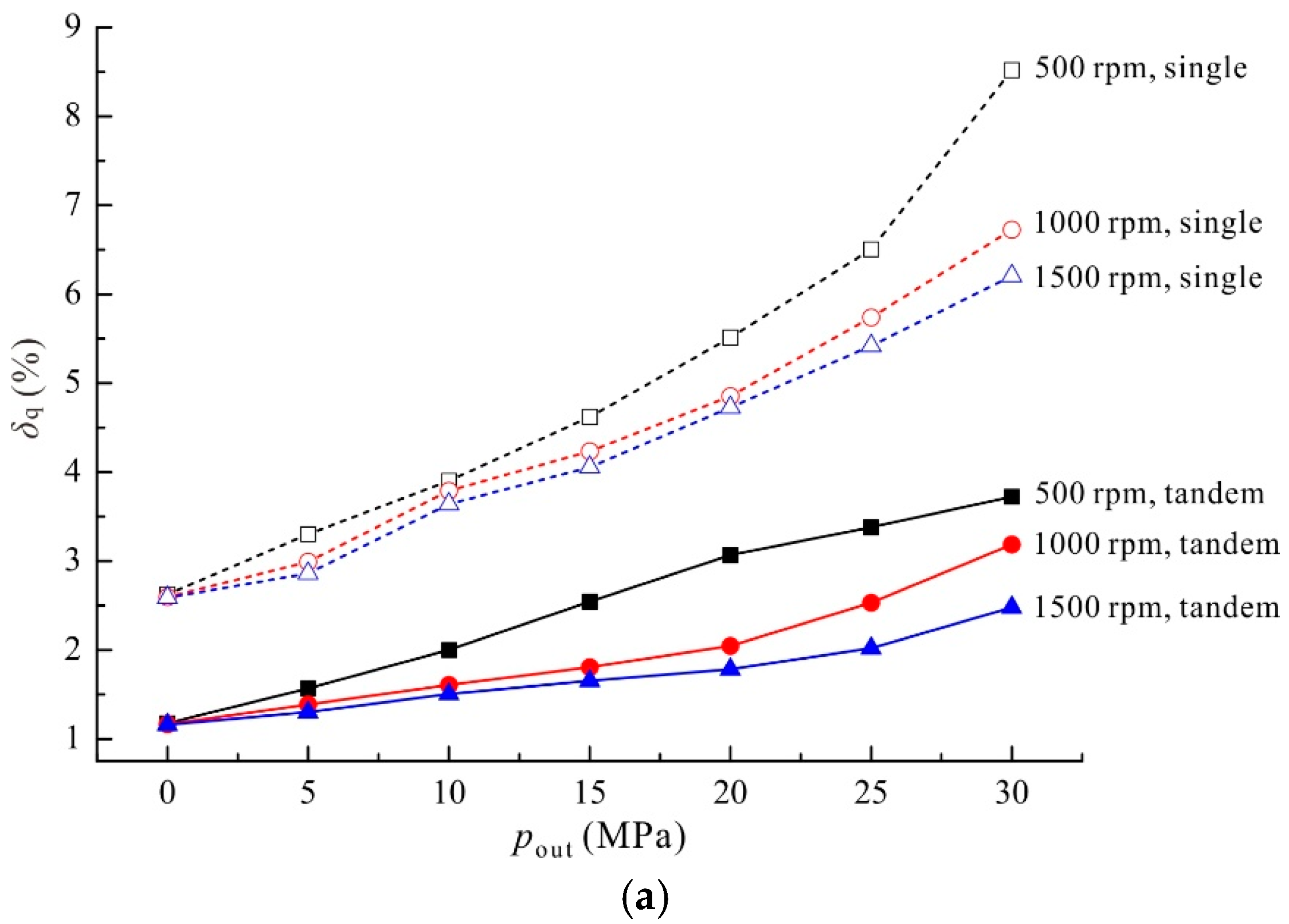
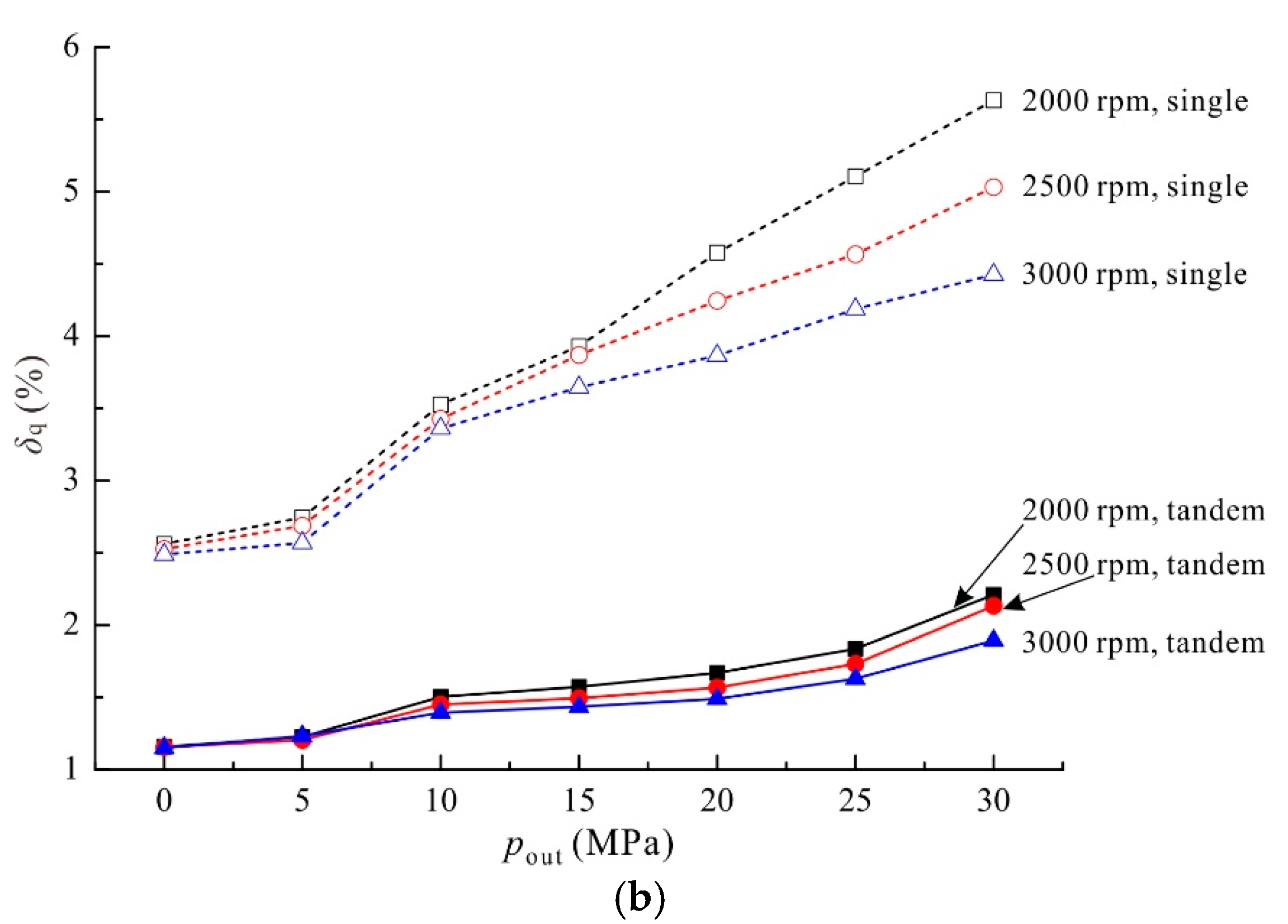
Figure 18 depicts the outlet flow ripples of the tandem pump (γ = λ/2 and ζ = 0.5) and the single pump under different operating conditions (500–3000 rpm, 0–30 MPa). It should be noted that the displacement of the tandem pump was 60 mL/rev given that the displacements of the two gear pairs were 40 mL/rev and 20 mL/rev, respectively; and the displacement of the single pump was 60 mL/rev for the purpose of maintaining the same mean outlet flowrate as the tandem pump when working under the same operating condition.
For these two types of pumps (tandem, single), it can be seen that with respect to a certain operating speed, the flow ripple increased as the outlet pressure increased. Furthermore, there was a clear and consistent trend that with respect to a certain outlet pressure, the flow ripple decreased as the operating speed increased. Moreover, the decrease of the flow ripple was noticed by applying the tandem pump with γ = λ/2 and ζ = 0.5. For instance, when working under 500 rpm and 30 MPa, the flow ripple of the single pump was 8.52% and the tandem pump was 3.72%; when working under 3000 rpm and 30 MPa, the flow ripple of the single pump was 4.42% and the tandem pump was 1.89%.
5. Discussion and Conclusions
In this section, we discuss the outlet flow of the pump to identify the main causes of the flow ripple. Additionally, the influence of the design parameters is discussed for the purpose of selecting the proper design parameters to enable a decrease of the crescent pump’s flow ripple.
5.1. Main Causes of the Flow Ripple
As observed in Figure 12, by applying Equation (25), the flow ripple of the kinematic flow (Qkin) yielded 6.8%, which is believed to be caused by the kinematic relations between the meshing gears. As stated above, the trapped flow (qtrap) was forced into the discharge chamber through the relief groove on the floating plate, thus leading to an increase in the outlet flow. Consequently, the with-trapped outlet flowrate (Qwt) yielded a greater mean outlet flowrate than that of Qkin. The flow ripple of Qwt in Figure 12 yielded 2.7%, an approximately 60% decrease than that of Qkin, indicating that the trapped flow plays an important role in decreasing the flow ripples. Regarding the internal leakage (qleak) and the triangular flow (qtri), it was clear that they led to a decrease in the outlet flow since they are the flow out of the discharge chamber. The flow ripple of Qout in Figure 12 yielded 4%, an approximate decrease of 41% than that of Qkin, but a 60% increase than that of Qwt, indicating that the internal leakage (qleak) and the triangular flow (qtri) led to an increase in the flow ripples.
Hence, it can be seen that the trapped flow led to a decrease in the flow ripple, while the triangular flow and the internal leakage of the pump led to an increase in the flow ripple; which was also consistent with the cases depicted in Figure 16.
5.2. Influence of Design Parameters
5.2.1. Influence of the Index Angle
As observed in Figure 14, the index angle (γ) had little influence on the mean outlet flowrate; however, it had a great influence on the outlet flow ripples. Referring to Figure 13, it can be seen that the index angle enabled a phase difference between the flow from the two gear pairs. Noting that the flow of the tandem pump was obtained by summing the flow from the two gear pairs, it was workable to attenuate the flow ripple of the tandem pump by properly selecting the index angle, therefore allowing the peak value of the flowrate from one gear pair to coincide with the valley value of the flowrate from the other gear pair. This is believed to be the reason why the index angle of 13.85° (λ/2) led to the greatest decrease in the flow ripple. As shown in Figure 16, the flow ripple was reduced by 66% from the maximum value (γ = 0) by properly selecting the index angle (γ = 13.85°).
5.2.2. Influence of the Displacement Ratio
The displacement ratio (ζ) led to different displacements of the pump, thus resulting in a different mean outlet flowrate in Figure 15 when working under the same operating condition. Under the circumstance of the same mean outlet flowrate, there was a value of the displacement ratio which enabled the greatest decrease in the flow ripple, and the value varied with respect to different index angles, as shown in Figure 17.
Referring to Figure 17, it can be seen that the index angle of 13.85° (λ/2) and the displacement ratio of 0.5 led to the greatest decrease in the outlet flow ripple, which was 10% lower than that of γ = 13.85° and ζ = 1 (flow ripple: 1.57%), and 70% lower than that of γ = 0 and ζ = 1 (flow ripple: 4.62%).
5.3. Influence of Operating Conditions
With respect to a certain operating speed, the internal leakage of the pump increased as the outlet pressure increased, and this is believed to be the reason why the flow ripple increased (the internal leakage leads to an increase in the flow ripple as discussed above). With respect to a certain outlet pressure, the mean outlet flowrate increased as the operating speed increased, and this is believed to be the reason why the flow ripple decreased (the denominator in Equation (25) became greater while the numerator remained roughly the same).
Referring to Figure 18, the tandem pump led to a more than 45% decrease in the flow ripple than the single pump with respect to the depicted operating conditions (500–3000 rpm, 0–30 MPa). Hence, it can be seen that a tandem crescent pump with proper design parameters (γ = 13.85° and ζ = 0.5) can result in a significant decrease in the outlet flow ripple (more than 45%) than a single pump with the same displacement across a wide range of operating conditions (500–3000 rpm, 0–30 MPa).
Acknowledgments
The authors are grateful to the anonymous reviewers and the editor for their constructive comments. The authors would also like to thank Xiaoping Ouyang from Zhejiang University for the improvement of the paper. Additionally, the authors would like to acknowledge the support of the National Natural Science Foundation of China (Grant No. 51521064) and Science and Technology Innovation Team of Independent Design Projects of Zhejiang Province (Grant No. 2013TD01).
Author Contributions
Hua Zhou and Ruilong Du proposed the idea of the tandem crescent pump for the purpose of decreasing the outlet flow ripple; Ruilong Du and Anhuan Xie conceived and designed the experiments; Huayong Yang contributed to the test rig; Ruilong Du and Anhuan Xie performed the experiments and analyzed the data; Ruilong Du wrote the Matlab code, conducted the numerical simulations and wrote the paper.
Conflicts of Interest
The authors declare no conflict of interest.
Notation
| Aval, rel, tri | flow area of the throttle valve, the relief groove, and the triangular groove (m2) |
| b | width of the gear (m) |
| bB, L1, L2 | parameters of the rectangular sealing area around the outlets (m) |
| Cd | discharge coefficient (-) |
| f | frequency (Hz) |
| l | length of the sealing area in the ring-gear/case interface(m) |
| lr | length of the tooth tip (m) |
| m | module of the gear (m) |
| n | operating speed (rpm) |
| Os,r | centers of the gear shaft and the ring gear (-) |
| p | pressure (Pa) |
| pin, out | inlet or outlet pressure (Pa) |
| ptran | transitional pressure (Pa) |
| ptrap | trapped pressure (Pa) |
| qin, out | flowrate into and out of a chamber (m3/s) |
| ql | lateral leakage of the lateral interface of the gears’ lateral sides and the floating plates (m3/s) |
| qleak | total internal leakage (m3/s) |
| qval, rel, tri | flowrate through the throttle valve, the relief groove and the triangular groove (m3/s) |
| qtri,s; tri,r | triangular flow for the gear shaft and the ring gear (m3/s) |
| qr | radial leakage of the radial interface of the tooth tips and the crescent fillers (m3/s) |
| qrc | leakage of the ring-gear/case interface (m3/s) |
| qtrap | trapped flow, flow out of the trapped chamber through the relief groove (m3/s) |
| Qmax, min | maximum and minimum flowrate (m3/s) |
| Qkin | kinematic outlet flow (m3/s) |
| Qwt | with-trapped flow by adding the kinematic flow and the trapped flow (m3/s) |
| Qout | actual outlet flow by adding the kinematic flow, the trapped flow, the leakage and the triangular flow (m3/s) |
| ra1, a2 | addendum radii of the gear shaft and the ring gear (m) |
| rf1, f2 | distances between the contact point and the centers of the gear shaft and ring gear (m) |
| rfp1, fp2 | radii of the inner and the outer border of the floating plate (m) |
| rp1, p2 | pitch radii of the gear shaft and the ring gear (m) |
| t | time (s) |
| V | volume (m3) |
| Vd | volume of the discharge chamber and the delivery line (m3) |
| Vkin | volume of the discharged fluid when the pump operates for a period of time t from the kinematic aspect (m3) |
| Vtrap | volume of the trapped chamber (m3) |
| VTS | volume of the tooth space (m3) |
| z1, 2 | tooth number of the gear shaft and the ring gear (-) |
| Greek symbols | |
| α0 | pressure angle of the gear (°) |
| α | operating pressure angle of the gear pair (°) |
| β | fluid bulk modulus (Pa) |
| γ | index angle (°) |
| δ | radial clearance between the ring gear and the case (m) |
| δl | lateral clearance between the gears’ lateral sides and the floating plates (m) |
| δq | flow ripple (-) |
| δr | radial clearance between the gears’ tooth tips and the fillers (m) |
| Δt | time interval (s) |
| ζ | displacement ratio (-) |
| η | volumetric efficiency (-) |
| θ | rotation angle of the gear shaft (°) |
| λ | circumferential angle of one tooth in the gear shaft (λ = 360°/z1) |
| μ | fluid viscosity (Pa·s) |
| ρ | fluid density (kg/ m3) |
| φ | angle circumference the sealing area in the ring-gear/case interface (rad) |
| ψ | sector angle of the annular sector for estimation of the lateral leakage (rad) |
| ω, ωr | angular velocity of the gear shaft and the ring gear (rad/s) |
References
- Zhou, H.; Song, W. Optimization of floating plate of water hydraulic internal gear pumps. In Proceedings of the 8th JFPS International Symposium on Fluid Power, Okinawa, Japan, 25–28 October 2011. [Google Scholar]
- Shi, Y.; Wu, T.; Cai, M.; Yixuan, W.; Weiqing, X. Energy conversion characteristics of a hydropneumatic transformer in a sustainable-energy vehicle. Appl. Energy 2016, 171, 77–85. [Google Scholar] [CrossRef]
- Shi, Y.; Wang, Y.; Cai, M.; Zhang, B.; Zhu, J. Study on the aviation oxygen supply system based on a mechanical ventilation model. Chin. J. Aeronaut. 2017. [Google Scholar] [CrossRef]
- Yang, H.; Pan, M. Engineering research in fluid power: A review. J. Zhejiang Univ. Sci. A 2015, 16, 427–442. [Google Scholar] [CrossRef]
- Mimmi, G.; Pennacchi, P. Involute gear pumps versus lobe pumps: A comparison. J. Mech. Des. 1997, 119, 458–465. [Google Scholar] [CrossRef]
- Bonandrini, G.; Mimmi, G.; Rottenbacher, C. Theoretical analysis of internal epitrochoidal and hypotrochoidal machines. Proc. Inst. Mech. Eng. C J. Mech. Eng. Sci. 2009, 223, 1469–1480. [Google Scholar] [CrossRef]
- Gamez-Montero, P.J.; Codina, E. Flow characteristics of a trochoidal-gear pump using bond graphs and experimental measurement. Part 1. Proc. Inst. Mech. Eng. I J. Syst. Control Eng. 2007, 221, 331–346. [Google Scholar] [CrossRef]
- Gamez-Montero, P.J.; Codina, E. Flow characteristics of a trochoidal-gear pump using bond graphs and experimental measurement. Part 2. Proc. Inst. Mech. Eng. I J. Syst. Control Eng. 2007, 221, 347–363. [Google Scholar] [CrossRef]
- Gamez-Montero, P.J.; Castilla, R.; del Campo, D.; Ertürk, N.; Raush, G.; Codina, E. Influence of the interteeth clearances on the flow ripple in a gerotor pump for engine lubrication. Proc. Inst. Mech. Eng. D J. Automob. Eng. 2012, 226, 930–942. [Google Scholar] [CrossRef]
- Hsieh, C.-F. Influence of gerotor performance in varied geometrical design parameters. J. Mech. Des. 2009, 131, 121008. [Google Scholar] [CrossRef]
- Hsieh, C.F. Flow characteristics of gerotor pumps with novel variable clearance designs. J. Fluids Eng. 2015, 137, 041107. [Google Scholar] [CrossRef]
- Manco, S.; Nervegna, N.; Rundo, M. A contribution to the design of hydraulic lube pumps. Int. J. Fluid Power 2002, 3, 21–32. [Google Scholar] [CrossRef]
- Schweiger, W.; Schoefmann, W.; Vacca, A. Gerotor pumps for automotive drivetrain applications: A multi domain simulation approach. SAE Int. J. Passeng. Cars-Mech. Syst. 2011, 4, 1358–1376. [Google Scholar] [CrossRef]
- Pellegri, M.; Vacca, A.; Frosina, E.; Buono, D.; Senatore, A. Numerical analysis and experimental validation of gerotor pumps: A comparison between a lumped parameter and a computational fluid dynamics-based approach. Proc. Inst. Mech. Eng. C J. Mech. Eng. Sci. 2016. [Google Scholar] [CrossRef]
- Pellegri, M.; Vacca, A. Numerical simulation of gerotor pumps considering rotor micro-motions. Meccanica 2017, 52, 1851–1870. [Google Scholar] [CrossRef]
- Ichikawa, T. Characteristics of internal gear pump. Bull. JSME 1959, 2, 35–39. [Google Scholar] [CrossRef]
- Zhou, H.; Song, W. Theoretical flowrate characteristics of the conjugated involute internal gear pump. Proc. Inst. Mech. Eng. C J. Mech. Eng. Sci. 2013, 227, 730–743. [Google Scholar] [CrossRef]
- Song, W.; Chen, Y.; Zhou, H. Investigation of fluid delivery and trapped volume performances of Truninger gear pump by a discretization approach. Adv. Mech. Eng. 2016, 8, 1–15. [Google Scholar] [CrossRef]
- Rundo, M. Theoretical flow rate in crescent pumps. Simul. Model. Pract. Theory 2017, 71, 1–14. [Google Scholar] [CrossRef]
- Rundo, M.; Corvaglia, A. Lumped parameters model of a crescent pump. Energies 2016, 9, 876. [Google Scholar] [CrossRef]
- Manring, N.D.; Mehta, V.S.; Raab, F.J.; Graf, K.J. The shaft torque of a tandem axial-piston pump. J. Dyn. Syst. Meas. Control 2007, 129, 367–371. [Google Scholar] [CrossRef]
- Mehta, V.S. Torque Ripple Attenuation for an Axial Piston Swash Plate Type Hydrostatic Pump: Noise Considerations. Ph.D. Thesis, University of Missouri, Columbia, SC, USA, 2006. [Google Scholar]
- Xu, B.; Ye, S.; Zhang, J. Effects of index angle on flow ripple of a tandem axial piston pump. J. Zhejiang Univ. Sci. A 2015, 16, 404–417. [Google Scholar] [CrossRef]
- Battarra, M.; Mucchi, E.; Dalpiaz, G. A model for the estimation of pressure ripple in tandem gear pumps. In Proceedings of the ASME 2015 International Design Engineering Technical Conference and Computers and Information in Engineering Conference, Boston, MA, USA, 2–5 August 2015. [Google Scholar]
- Xu, B.; Zhang, J.; Yang, H. Simulation research on distribution method of axial piston pump utilizing pressure equalization mechanism. Proc. Inst. Mech. Eng. C J. Mech. Eng. Sci. 2013, 227, 459–469. [Google Scholar] [CrossRef]
- Ivantysyn, J.; Ivantysynova, M. Hydrostatic Pumps and Motors, 1st ed.; Academia Books International: New Delhi, India, 2001; ISBN 81-85522-16-2. [Google Scholar]
- Ma, J.; Fang, Y.; Xu, B.; Yang, H. Optimization of cross angle based on the pumping dynamics model. J. Zhejiang Univ. Sci. A 2010, 11, 181–190. [Google Scholar] [CrossRef]
- Hamrock, B.J.; Schmid, S.R.; Jacobson, B.O. Fundamentals of Fluid Film Lubrication, 2nd ed.; Marcel Dekker, Inc.: New York, NY, USA, 2004; ISBN 0-8247-5371-2. [Google Scholar]
Figure 1.
(a) A schematic of the tandem crescent pump design; and (b) a schematic of the two sets of gear pairs with an index angle (view A-A and B-B).
Figure 1.
(a) A schematic of the tandem crescent pump design; and (b) a schematic of the two sets of gear pairs with an index angle (view A-A and B-B).
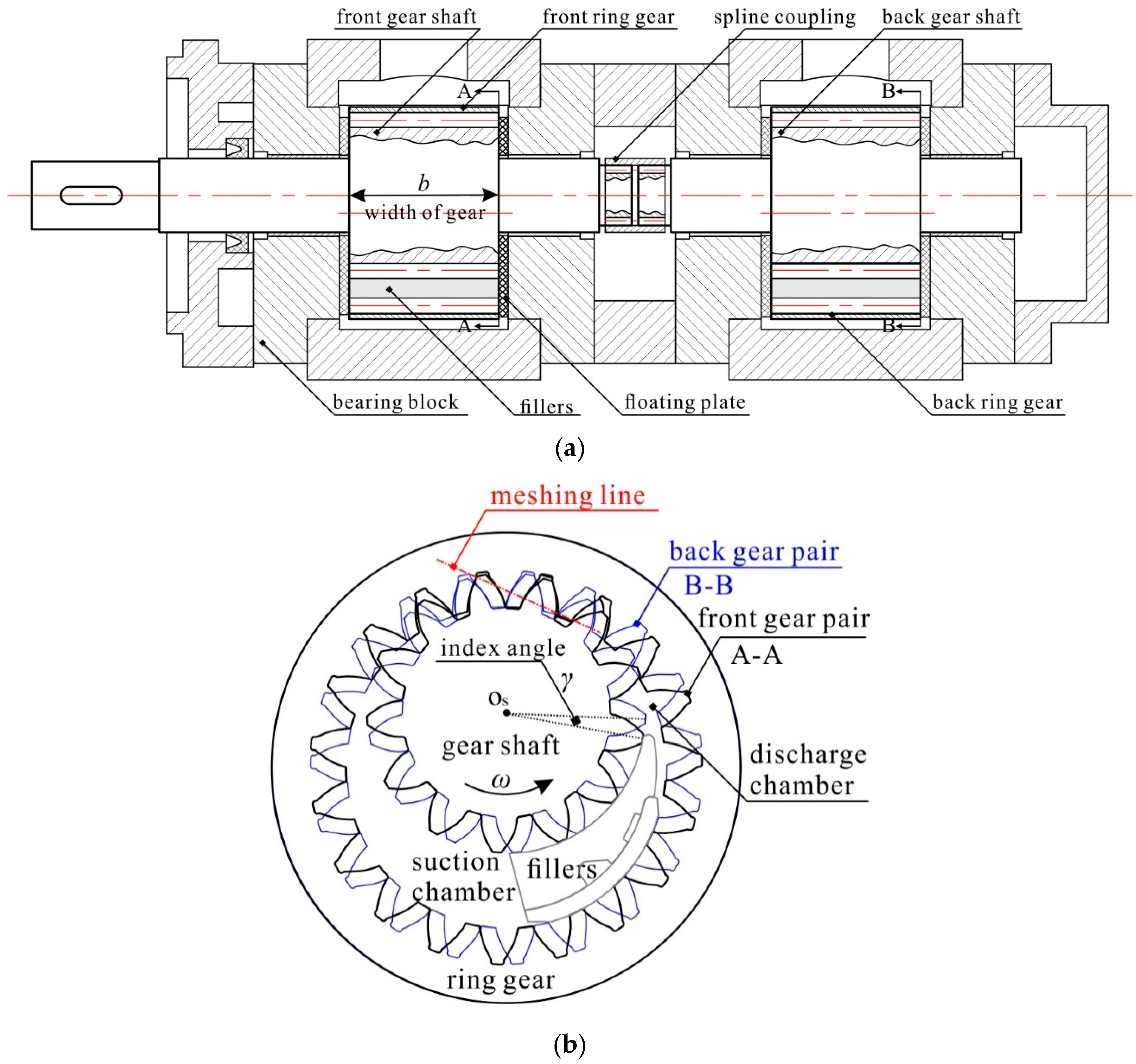
Figure 2.
Definition of the sealing chambers around the gear circumference.
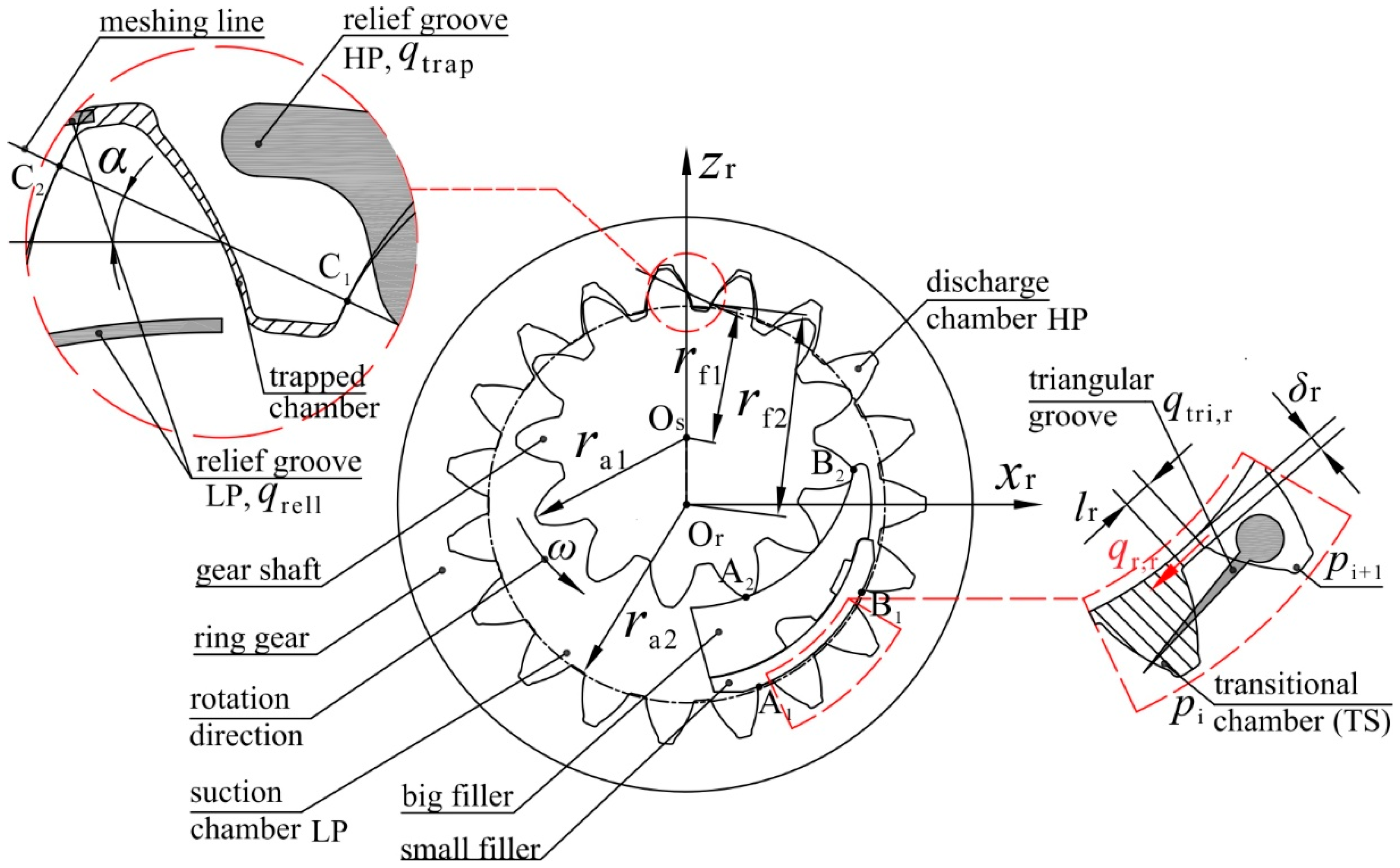
Figure 3.
The triangular grooves and the relief grooves machined on the floating plate.

Figure 4.
A hydraulic system for estimating the crescent pump’s flow-pressure characteristics.
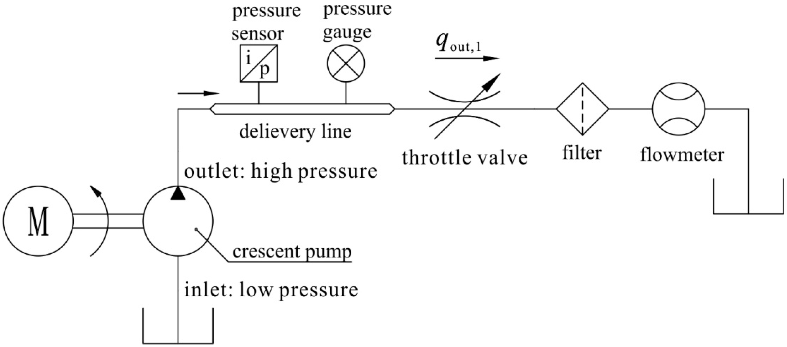
Figure 5.
Lateral leakage that goes through the gear shaft’s side and the ring gear’s side.
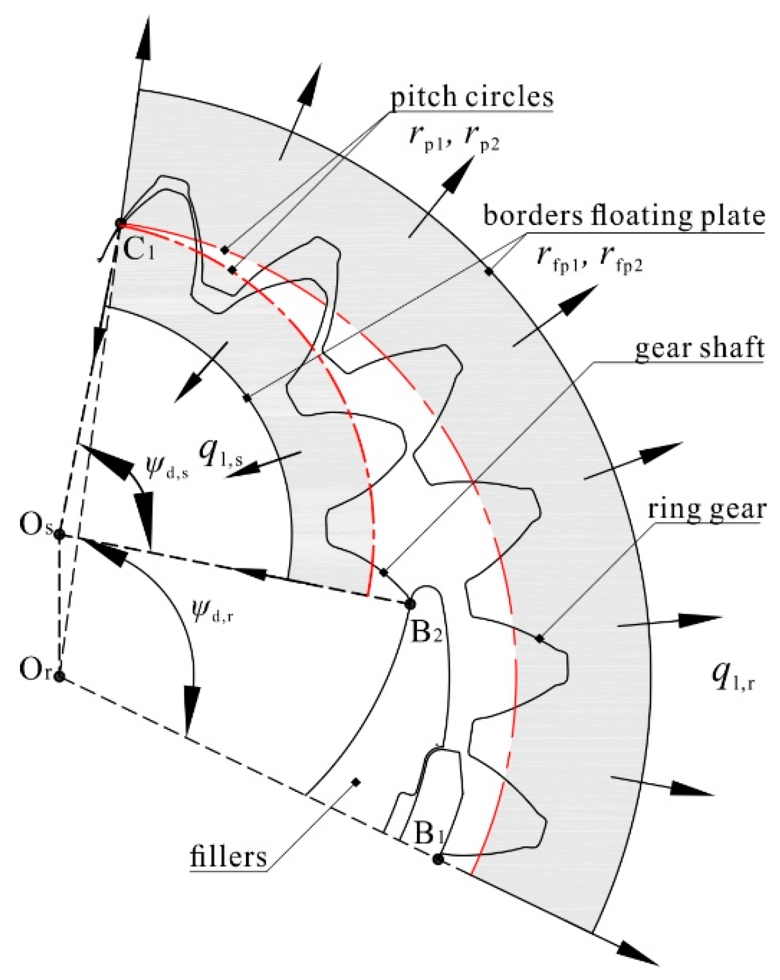
Figure 6.
(a) Cross section of the case depicting the rectangular sealing areas surrounding the outlets; and (b) the rectangular sealing area unwrapped on a plane.
Figure 6.
(a) Cross section of the case depicting the rectangular sealing areas surrounding the outlets; and (b) the rectangular sealing area unwrapped on a plane.
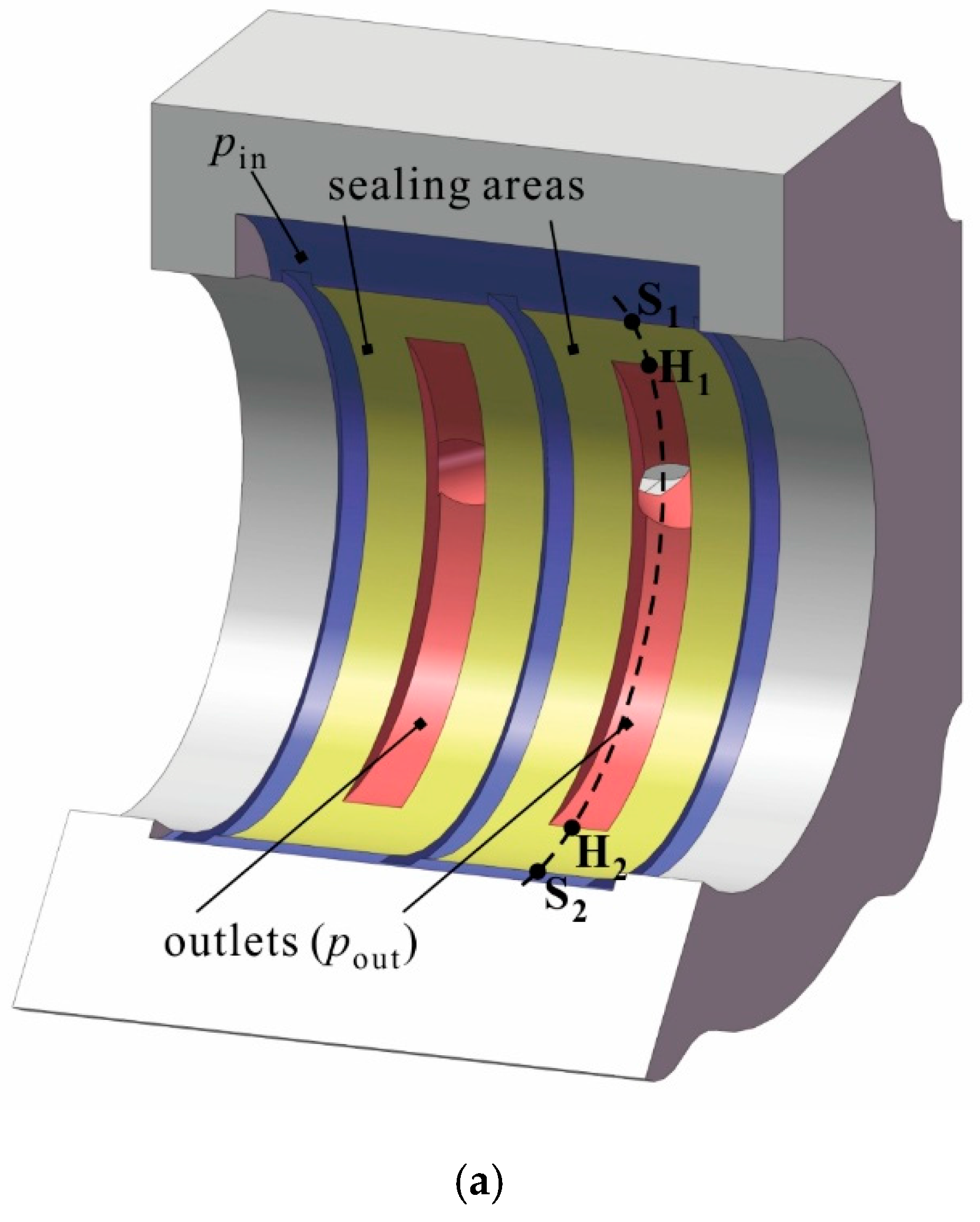

Figure 7.
Solution algorithm for analyzing the tandem crescent pump’s flow characteristics.
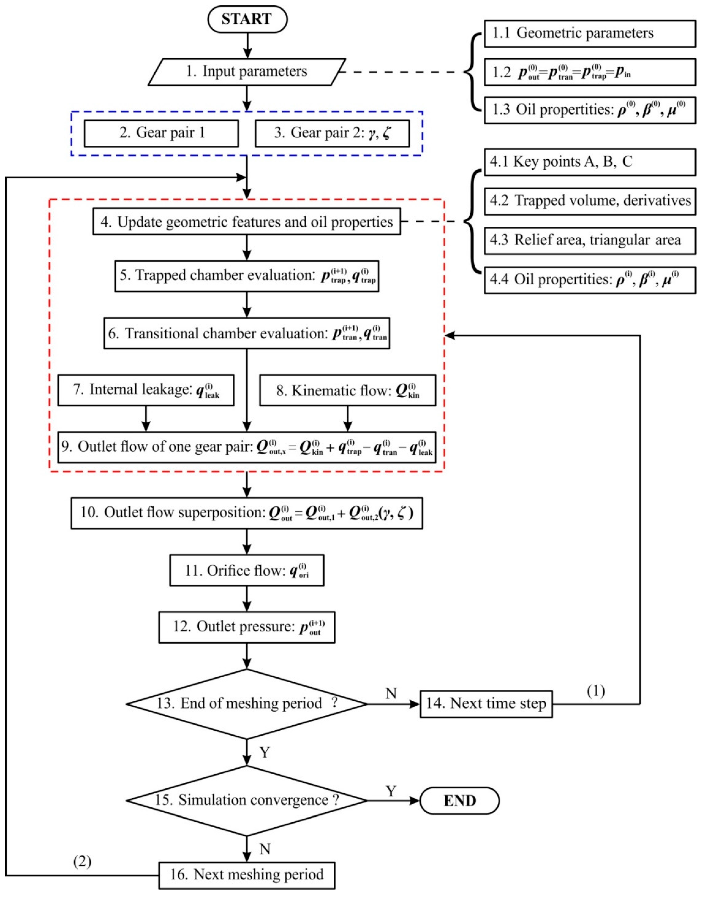
Figure 8.
Test rig for measuring the single crescent pump’s steady-state flowrate and outlet pressure ripples.
Figure 8.
Test rig for measuring the single crescent pump’s steady-state flowrate and outlet pressure ripples.
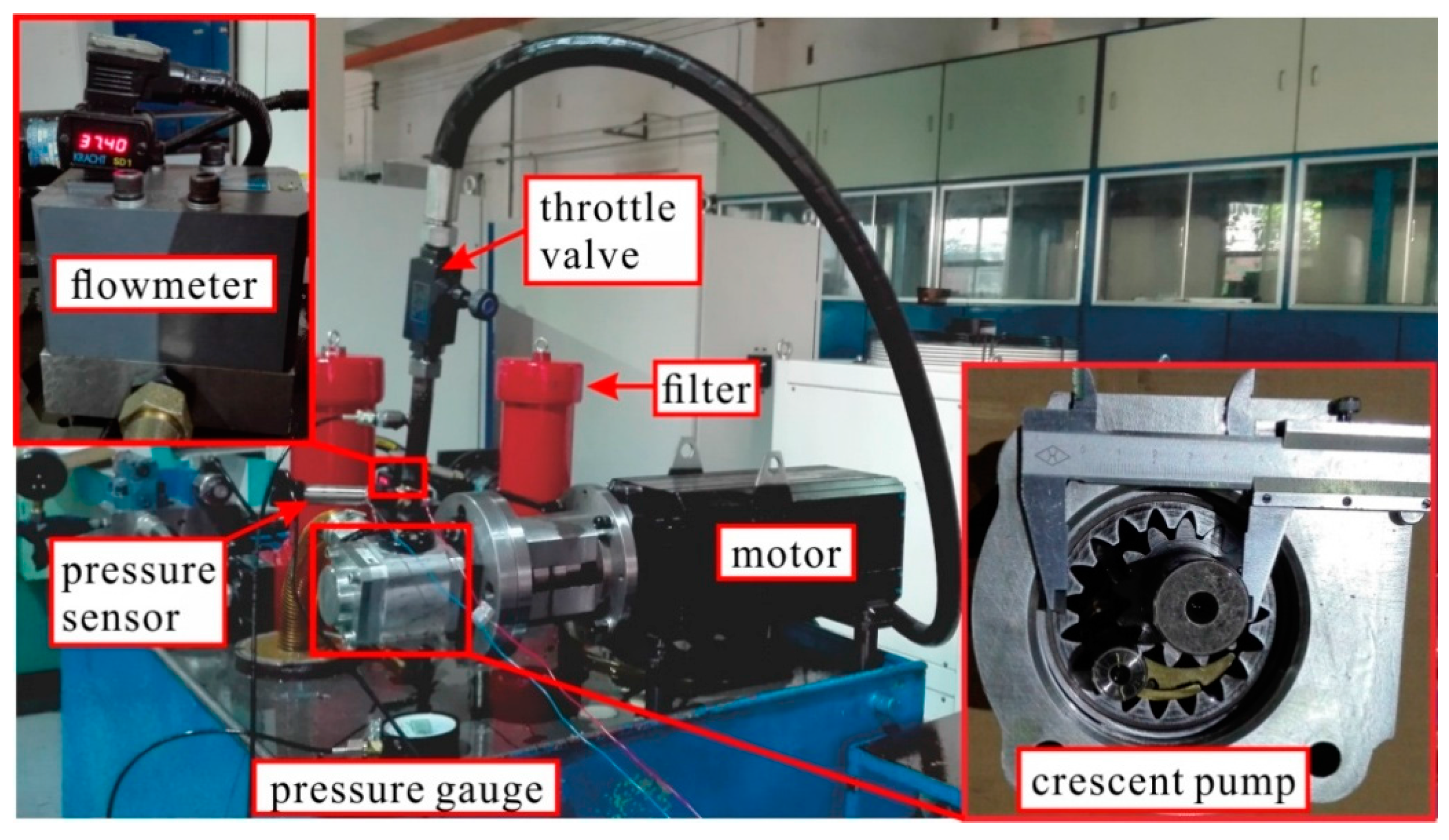
Figure 9.
Steady-state flow characteristics regarding different operating speeds (500–2000 rpm) and outlet pressures (5–20 MPa): (a) outlet flowrate; and (b) volumetric efficiency.
Figure 9.
Steady-state flow characteristics regarding different operating speeds (500–2000 rpm) and outlet pressures (5–20 MPa): (a) outlet flowrate; and (b) volumetric efficiency.

Figure 10.
Comparison of outlet pressure ripples regarding different operating conditions: (a) 500 rpm, 5 MPa; (b) 500 rpm, 20 MPa; and (c) 2000 rpm, 20 MPa.
Figure 10.
Comparison of outlet pressure ripples regarding different operating conditions: (a) 500 rpm, 5 MPa; (b) 500 rpm, 20 MPa; and (c) 2000 rpm, 20 MPa.
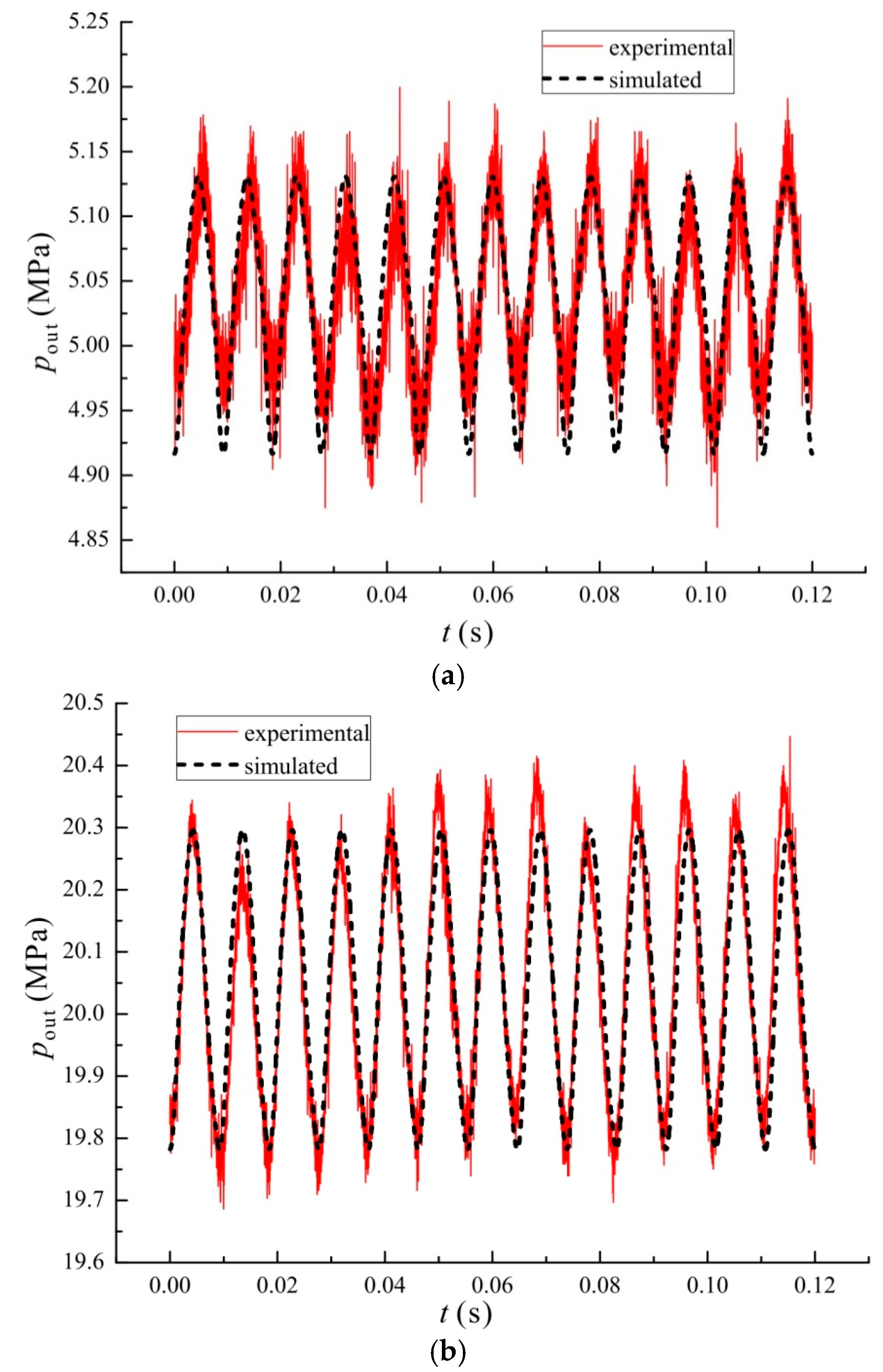
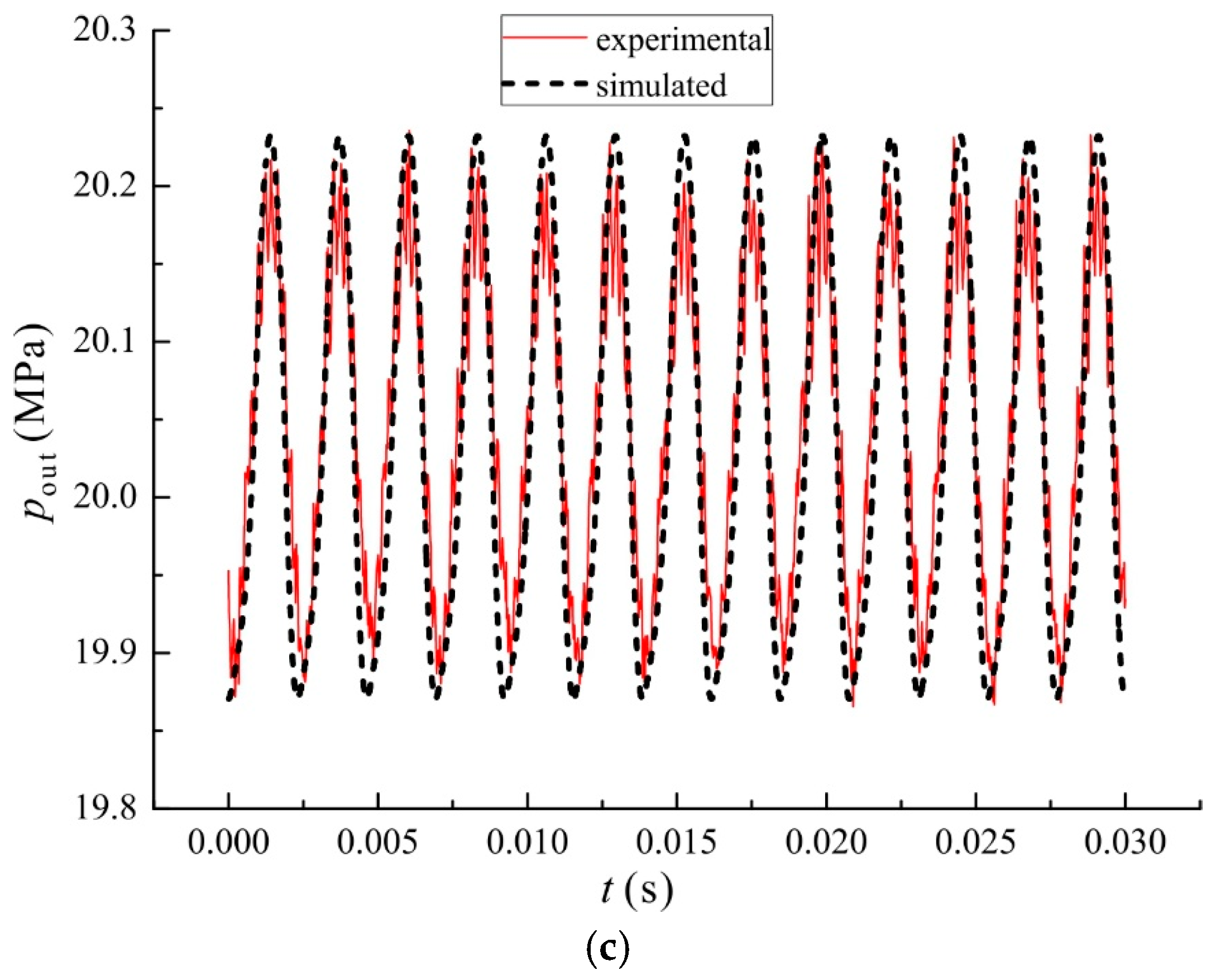
Figure 11.
Frequency spectra of simulated and experimental outlet pressure ripples at 500 rpm, 20 MPa.
Figure 11.
Frequency spectra of simulated and experimental outlet pressure ripples at 500 rpm, 20 MPa.
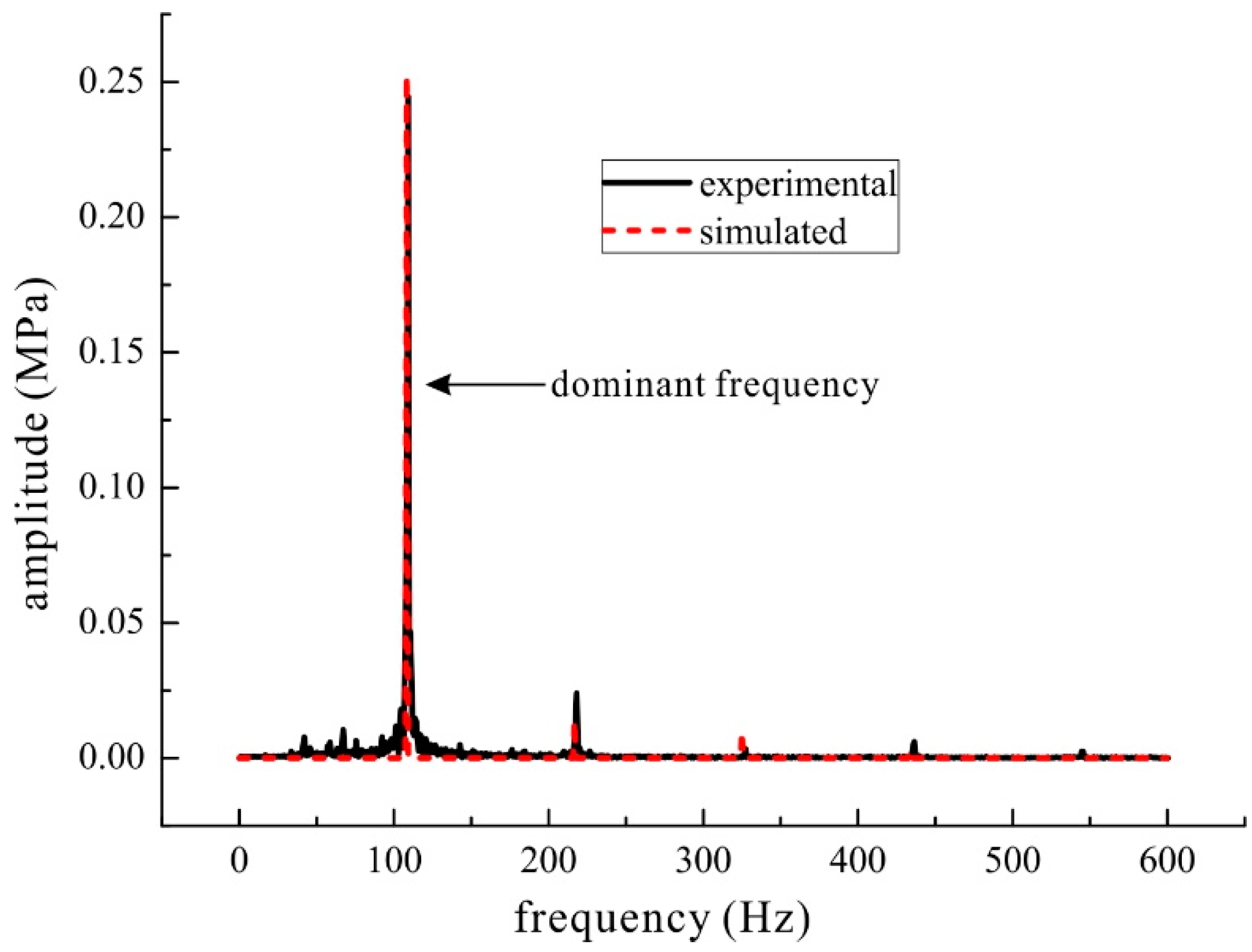
Figure 12.
Three types of outlet flow from one gear pair under 2000 rpm and 20 MPa.
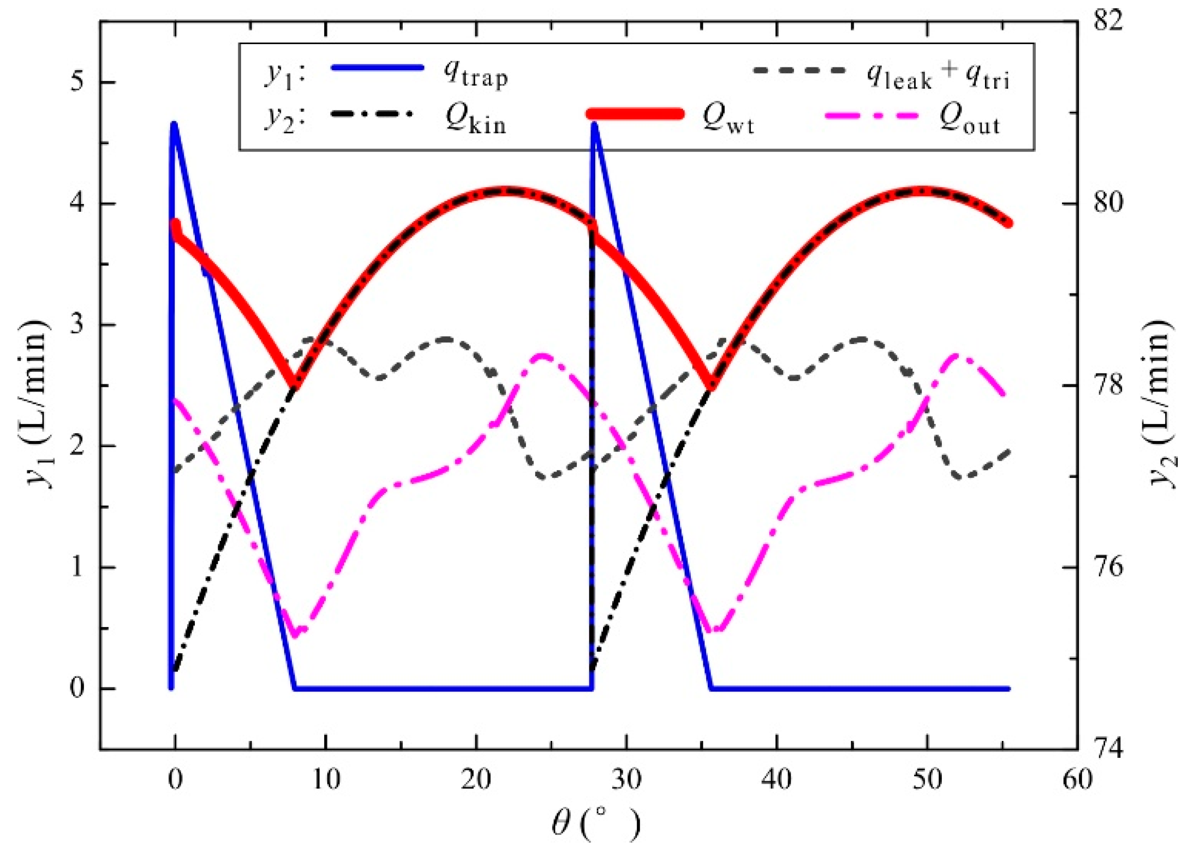
Figure 13.
Outlet flow from two indexed gear pairs under 2000 rpm and 20 MPa (ζ = 1).

Figure 14.
Outlet flow from the tandem pump (ζ = 1) under 2000 rpm and 20 MPa regarding different index angles.
Figure 14.
Outlet flow from the tandem pump (ζ = 1) under 2000 rpm and 20 MPa regarding different index angles.
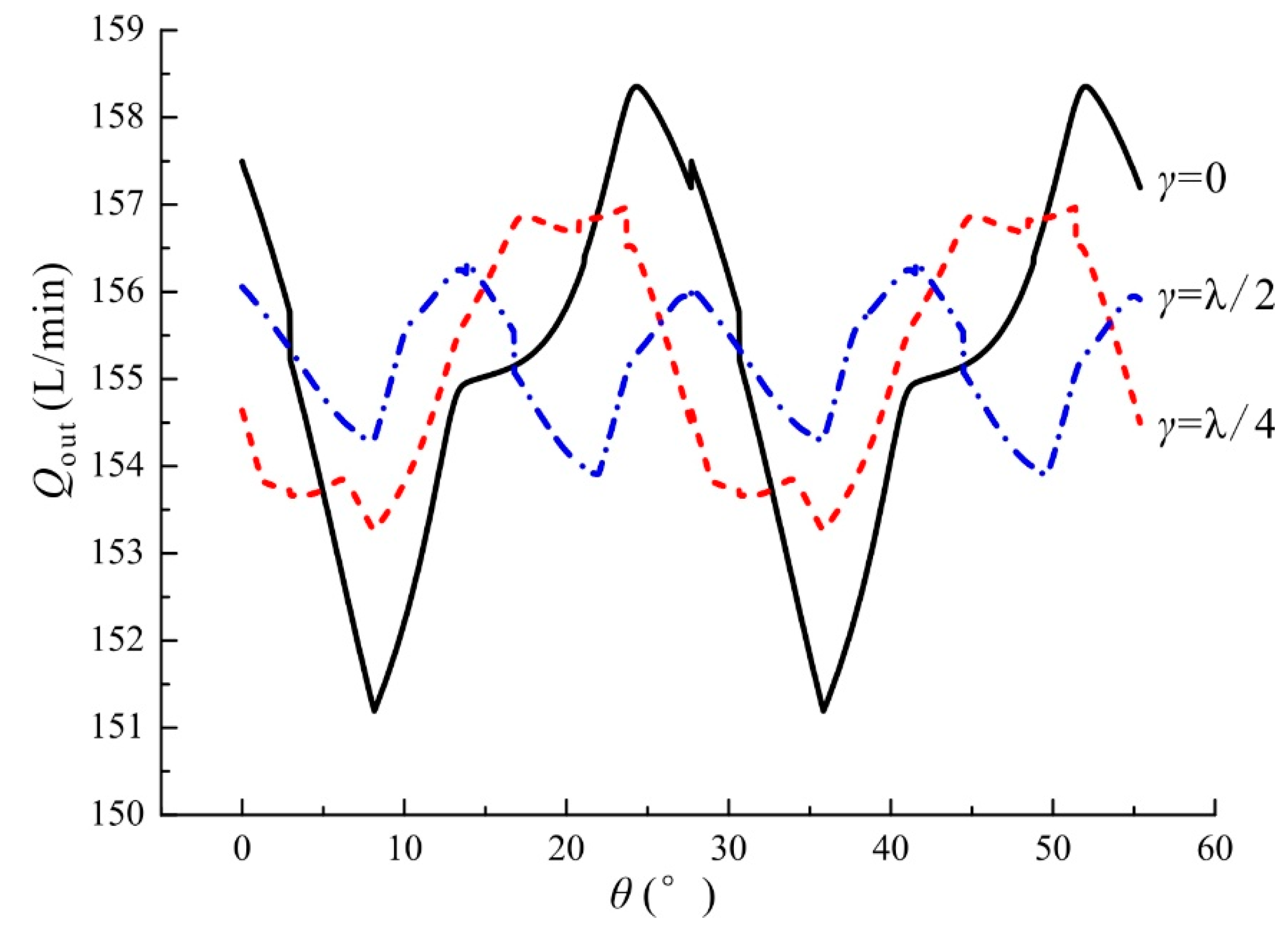
Figure 15.
Outlet flow from the tandem pump (γ = λ/2) under 2000 rpm and 20 MPa regarding different displacement ratios.
Figure 15.
Outlet flow from the tandem pump (γ = λ/2) under 2000 rpm and 20 MPa regarding different displacement ratios.
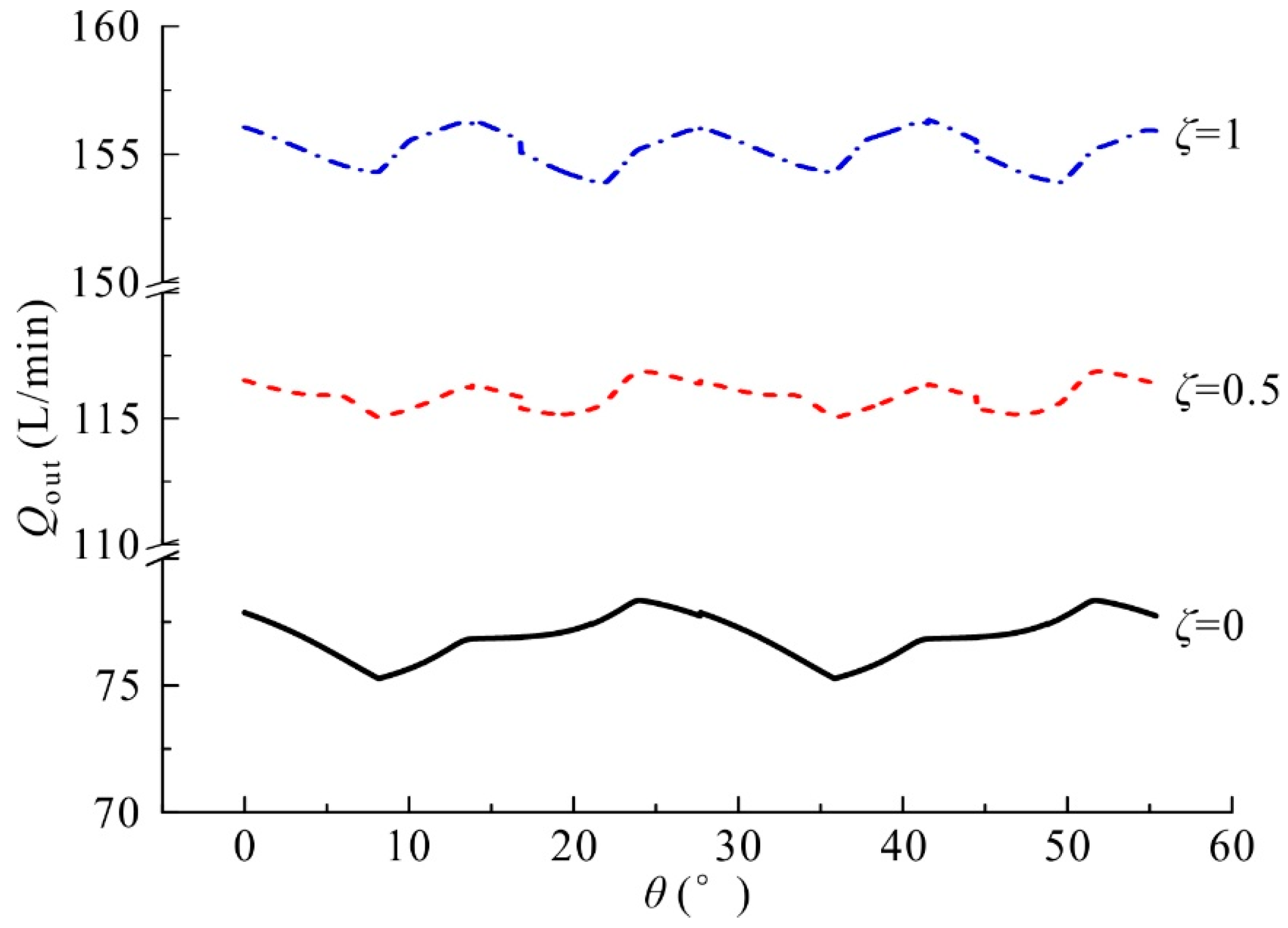
Figure 16.
Flow ripple of the tandem pump (ζ = 1) under 2000 rpm and 20 MPa regarding different index angles.
Figure 16.
Flow ripple of the tandem pump (ζ = 1) under 2000 rpm and 20 MPa regarding different index angles.

Figure 17.
Flow ripple of the tandem pump at 20 MPa regarding different displacement ratios under the same mean outlet flowrate (Qout).
Figure 17.
Flow ripple of the tandem pump at 20 MPa regarding different displacement ratios under the same mean outlet flowrate (Qout).

Figure 18.
Flow ripples of the tandem pump and the single pump under different operating conditions: (a) 500–1500 rpm; and (b) 2000–3000 rpm.
Figure 18.
Flow ripples of the tandem pump and the single pump under different operating conditions: (a) 500–1500 rpm; and (b) 2000–3000 rpm.


Table 1.
Main features of the flowmeter and the pressure sensor.
| Sensor | Type | Main Feature |
|---|---|---|
| Flowmeter | Kracht®, Germany, VC5F1PV | scale: 1–250 L/min, 0.3% accuracy (from measured value) |
| Pressure sensor | Shuangqiao®, China, CYG1401F | scale: 0–35 MPa, 0.5% FS accuracy, 0.5% nonlinearity, 100 KHz natural frequency |
Table 2.
Main geometric parameters of the crescent pump.
| Parameter | Notation | Value | Unit |
|---|---|---|---|
| Module of the gear | m | 3 | mm |
| Tooth numbers of the gear shaft and the ring gear | z1, z2 | 13, 19 | -- |
| Pressure angle of the gear | α0 | 22 | ° |
| Operating pressure angle of the gear pair | α | 24.87 | ° |
| Width of the gear | b | 55 | mm |
| Addendum and pitch radii of the gear shaft | ra1, rp1 | 23.43, 19.5 | mm |
| Addendum and pitch radii of the ring gear | ra2, rp2 | 26.95, 28.5 | mm |
| Radii of inner and outer borders of the floating plate | rfp1, rfp2 | 15.5, 38.25 | mm |
© 2017 by the authors. Licensee MDPI, Basel, Switzerland. This article is an open access article distributed under the terms and conditions of the Creative Commons Attribution (CC BY) license (http://creativecommons.org/licenses/by/4.0/).
Share and Cite
MDPI and ACS Style
Zhou, H.; Du, R.; Xie, A.; Yang, H. Theoretical Analysis for the Flow Ripple of a Tandem Crescent Pump with Index Angles. Appl. Sci. 2017, 7, 1148. https://doi.org/10.3390/app7111148
AMA Style
Zhou H, Du R, Xie A, Yang H. Theoretical Analysis for the Flow Ripple of a Tandem Crescent Pump with Index Angles. Applied Sciences. 2017; 7(11):1148. https://doi.org/10.3390/app7111148
Chicago/Turabian StyleZhou, Hua, Ruilong Du, Anhuan Xie, and Huayong Yang. 2017. "Theoretical Analysis for the Flow Ripple of a Tandem Crescent Pump with Index Angles" Applied Sciences 7, no. 11: 1148. https://doi.org/10.3390/app7111148
Note that from the first issue of 2016, this journal uses article numbers instead of page numbers. See further details here.