Backstepping Based Formation Control of Quadrotors with the State Transformation Technique


1
School of Electrical and Electronic Engineering, Yonsei University, Seodaemun-Gu, Seoul 03722, Korea
2
Department of Electronic Engineering, Kyonggi University, Suwon 16227, Kyonggi-Do, Korea
*
Author to whom correspondence should be addressed.
Appl. Sci. 2017, 7(11), 1170; https://doi.org/10.3390/app7111170
Submission received: 4 October 2017
/
Revised: 3 November 2017
/
Accepted: 8 November 2017
/
Published: 14 November 2017
Abstract
:In this paper, a backstepping-based formation control of quadrotors with the state transformation technique is proposed. First, the dynamics of a quadrotor is derived by using the Newton–Euler formulation. Next, a backstepping-based formation control for quadrotors using a state transformation technique is presented. In the position control, which is the basis of formation control, it is possible to derive the reference attitude angles employing a state transformation technique without the small angle assumption or the simplified dynamics usually used. Stability analysis based on the Lyapunov theorem shows that the proposed formation controller can provide a quadrotor formation error system that is asymptotically stabilized. Finally, we verify the performance of the proposed formation control method through comparison simulations.
1. Introduction
Unmanned aerial vehicles (UAVs) have received much attention in the past few years due to their great potential applications in exploration, transportation, reconnaissance and surveillance. Among all the UAVs, the quadrotor is the most widely used because of its easy implementation compared to other aerial vehicles, its vertical take-off and landing (VTOL) ability and its high agility and maneuverability.
Recently, there has been significant research interest in quadrotor applications especially those using multiple quadrotors. By operating multiple quadrotors, tasks that are impossible with a single quadrotor can be performed, and single quadrotor tasks can be performed faster and more efficiently. Therefore, there has been considerable attention on studies focusing on quadrotor formation control [1,2,3,4,5,6,7,8,9,10,11,12,13,14]. There are several quadrotor formation control methodologies including behavior based [1], leader-follower [2,3,4,5,6,7,8], virtual structures [9,10] and graph theory [11,12,13,14]. Among these methodologies for the formation control, the leader-follower approach is well recognized as the most popular and intuitive approach [15]. In the leader-follower approach, one of the agents in the formation is designated as a leader, and the other members are defined as the followers. The leader transmits its state information to the followers, but it does not receiving any information from the followers. However, the followers can transmit and receive information.
The formation control methodologies mentioned above commonly require precise position control of each quadrotor for precise formation control of multiple quadrotors. However, since the quadrotor system is an underactuated system in which the number of outputs is greater than the number of inputs, the precise position control of a quadrotor is not easy to achieve since the and z position system of a quadrotor is connected to only one altitude input unlike the attitude system of a quadrotor. Therefore, the x and y positions of the quadrotor are not directly controlled by the inputs. This is why the precise position control of a quadrotor is not easy.
Position control based on linear control methods such as proportional-integral-differential (PID) and the linear quadratic regulator (LQR) has been proposed [2,3,5,16,17], but it has limited performance because it was only focused on the local behavior of the system. Considering the nonlinear dynamics of a quadrotor, various nonlinear control methods have been proposed. Many researchers applied the backstepping control method to solve the problem of the position control mentioned above [4,8,18,19,20,21,22,23,24,25,26,27,28]. The position control of a quadrotor using the backstepping method can be roughly classified in two ways. The first one is to derive the reference attitude angles for the position control and formation control [4,18,20,21,22,23,24,27,28]. The other one is to derive the final inputs of a quadrotor by connecting the position to the attitude dynamics of the quadrotor without the use of reference attitude angles [19,25,26]. However, this approach has the disadvantage that it is difficult to actually implement because the final input formula is complicated and there is much computational burden with respect to the input. Therefore, most researchers commonly use the method to derive the reference attitude angles for the position and formation controls and the position and formation controls achieved through attitude tracking control of the reference attitude angles [29,30]. However, it is not easy to derive the reference attitude angles from the position dynamics of a quadrotor consisting of several coupled trigonometric functions. Therefore, in most studies, the reference attitude angles for the backstepping-based position control are obtained through simplified quadrotor dynamics or linearization methods such as the small angle assumption (SAA) [4,18,21,22,23,28]. The SAA assumes that the ranges of the quadrotor attitude angles are small or zero, which works well when a quadrotor operates with small attitude angles. However, a quadrotor cannot maintain good tracking performance when the attitude angles vary in a broad range.
In this paper, we present the backstepping-based quadrotor formation control with the state transformation technique. We can derive the reference attitude angles for the formation control without the use of simple position quadrotor dynamics and the special assumption such as SAA. By using the state transformation technique for both small and large variations in attitude angles, improved performance is expected not only in the position control of a single quadrotor, but also in the formation control of multiple quadrotors.
We first derive the quadrotor dynamics using the Newton–Euler formulation. Next, we formulate the formation control problem based on the leader-follower method of quadrotors. Then, we present the backstepping-based quadrotor formation control with the state transformation technique. Stability analysis based on the Lyapunov theorem shows that the proposed formation control method results in a quadrotor formation error system that is asymptotically stabilized. Finally, using comparison simulations with other control methods, we verify the effectiveness of the proposed formation control method.
The remainder of this paper is as follows: In Section 2, we describe the dynamics of a quadrotor. In Section 3, we formulate the leader-follower formation control problem and present the backstepping-based quadrotor formation control using the state transformation technique. We also show the stability of the proposed quadrotor formation control. In Section 4, we present the simulation results and conclude the paper in Section 5.
2. Dynamic Model of a Quadrotor
First of all, to derive the equations for the movement of a quadrotor, we have to define the coordinates of a quadrotor system. The generalized coordinates and each thrust of a quadrotor system are shown in Figure 1, where B and E denote the body-fixed and Earth inertial frames, respectively.
The kinematics of a generic six-DOF rigid-body is described as follows:
where and are the velocity vectors with respect to the Earth inertial and body-fixed frames, respectively. Here, , , and . Additionally, is a three by three submatrix filled with all zeros; the coordinate transformation matrix from the body-fixed frame to the Earth inertial frame R, the angle-rates transformation matrix from the body-fixed frame to the Earth-inertial frame T are defined, respectively, as follows:
where , and .
To describe the quadrotor dynamic model, we use the Newton–Euler formalism. The dynamics of a generic six-DOF rigid-body takes into account the mass of the body and its inertia. The dynamics is described by:
where m is the mass of a quadrotor and denotes a three by three identity matrix. The matrix, , is the force vector; is the torque vector of the body-fixed frame. Finally, the dynamics of a quadrotor represented by (4) can be rewritten as follows:
where J is the rotor inertia, (for ) is the total inertia moment of each axis of a quadrotor, g is the gravitational acceleration and are the altitude, the roll, the pitch and the yaw control inputs represented by:
Here, is the propeller speed of the i-th rotor, l is the distance between the center of a quadrotor and the center of a propeller and b and d are the thrust and drag factors of a quadrotor.
The dynamics of a quadrotor represented by (5) can be expressed in state-space form (7) using the following states:
In this paper, to design the leader-follower formation controller, we use the following assumption:
Assumption 1.
In the quadrotor formation control, the followers can estimate perfectly the states of the leader such as position, velocity, and so on.
3. Backstepping-Based Quadrotor Formation Control
In this section, we design the leader-follower quadrotor formation controller based on the backstepping control method. We use the state transformation technique to derive the reference attitude angles for the formation control without any special assumption such as SAA.
3.1. Leader-Follower Formation Control
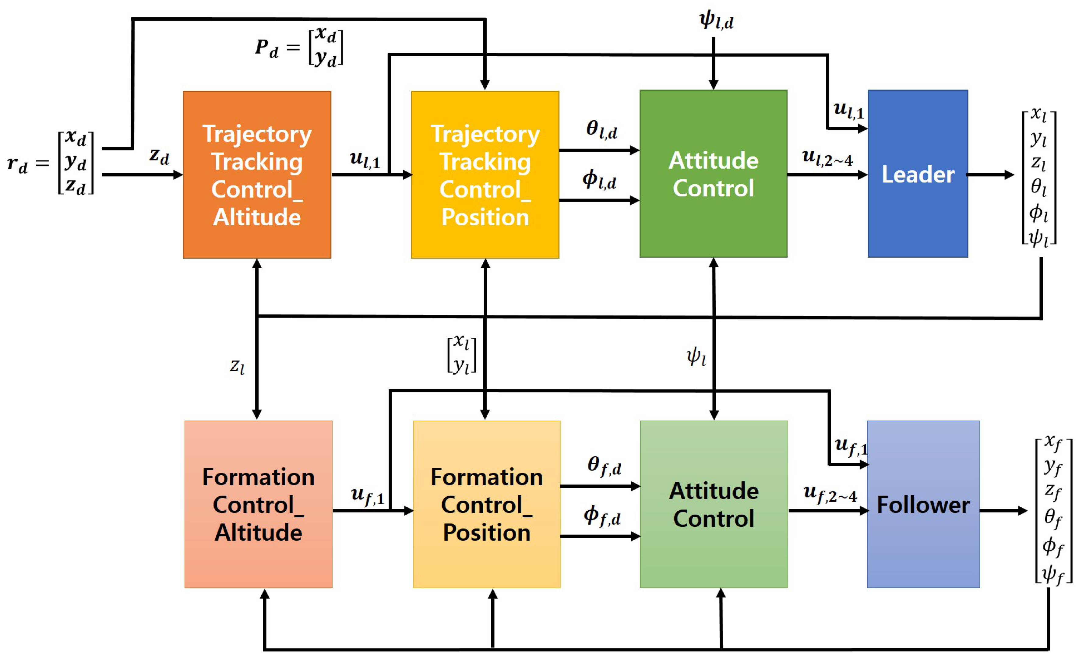
The formation control strategy used in this paper is as follows: first, the leader tracks the predefined trajectory, and the followers follow the leader with a certain distance from the leader. In the altitude controller of the leader, an altitude control input is created to track the reference altitude. Next, in the position controller, using the designed altitude control input, the reference roll and pitch angles are calculated for the leader to track the predefined position trajectory. The leader can track the predefined trajectory through the attitude tracking control with the previously calculated reference roll and pitch angles. On the other hand, the followers have a control scheme similar to the leader’s trajectory tracking control. Instead of the predefined trajectory given to the leader, the x, y and z positions of the leader and the set relative distance between the followers and leader are used for the formation control of the followers. The overall proposed formation control system block diagram is shown in Figure 2. In this paper, the same backstepping-based control strategy can be used for both the leader and the followers.
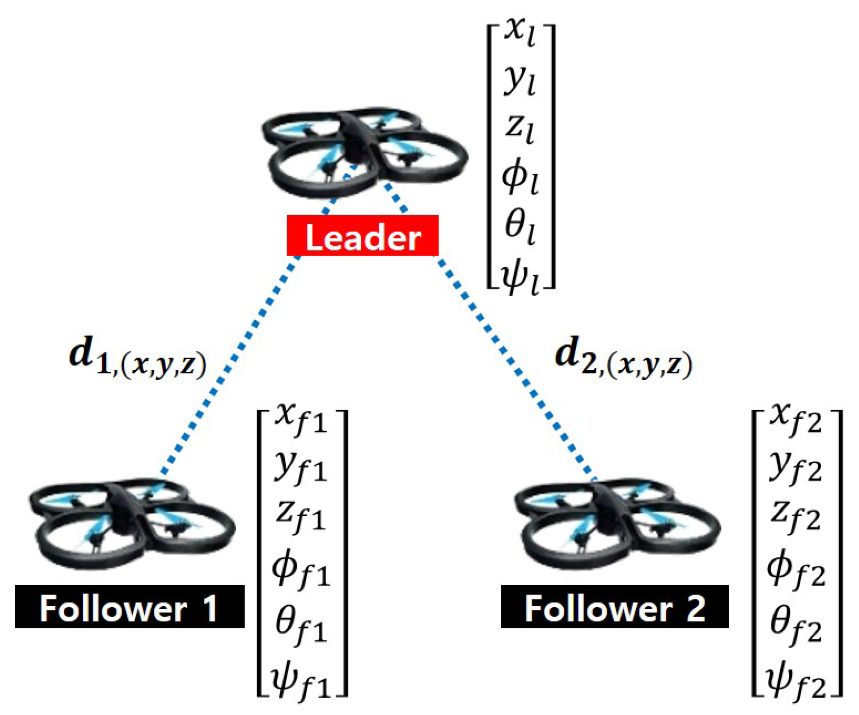
A leader-follower structure example consisting of three quadrotors is shown in Figure 3. Here, the position and attitude angles of each quadrotor are represented by , where the subscript l denotes the leader and f denotes a follower. The formation configuration is specified by the desired vector between the leader and a follower. As shown in Figure 3, each follower maintains the formation separated by the relative distance , from the leader quadrotor.
3.2. Altitude Control of a Quadrotor
In this subsection, we derive the altitude control input for the formation control on the z-axis using the state transformation technique. This altitude control input is used for the position control in the next subsection. In this paper, we derive the controller by assuming that both the leader and the follower quadrotors have the same dynamics.
First, the altitude dynamics of the i-th follower can be expressed using quadrotor dynamics in (7) as follows:
where is the pseudo altitude control input of the i-th follower defined by:
and is the first state transformation variable of the i-th follower given by:
To design the pseudo control input of the i-th follower using the backstepping technique, the first formation error related to the altitude of the i-th follower is the difference between the z-axis distance that the leader and follower must maintain and the actual z-axis distance, and the definition is as follows:
where is the relative z-axis distance between the leader and the i-th follower and is the desired relative z-axis distance between the leader and the i-th follower.
Differentiating the first formation error related to the altitude of the i-th follower with respect to time, we obtain:
where is the derivative of the relative z-axis distance between the leader and the i-th follower.
Assuming is given as , (11) can be rewritten as follows:
If , the above error dynamics becomes stable system, then the error converges to zero. Therefore, supposing as a virtual altitude control input and defining it as , the virtual altitude control input of the i-th follower to converge the first formation error related to the altitude of the i-th follower to zero is given by:
where is a positive constant.
Next, the second formation error related to the altitude of the i-th follower is the difference in velocity between the leader and follower on the z-axis, and the definition is as follows:
Differentiating the second formation error related to the altitude of the i-th follower with respect to time and substituting (8), we obtain:
The pseudo altitude control input of the i-th follower to converge the second formation error related to the altitude of the i-th follower to zero is given by:
where is a positive constant.
In this paper, we use the following assumption.
Assumption 2.
The attitude angles of the i-th follower , and satisfy the following conditions:
Therefore, based on the definition of in (8) and (9), we can derive the actual altitude control input of the i-th follower as follows:
Theorem 1.
Consider the altitude system of the i-th follower in (8) controlled by the virtual and pseudo altitude control inputs of the i-th follower in (12) and (14), respectively. Then, there exist the design parameters and such that the actual altitude control input of the i-th follower in (15) asymptotically stabilizes the formation error system related to the altitude of the i-th follower in (11) and (13).
Proof.
Let us consider the following Lyapunov function candidate:
Therefore, by the Lyapunov stability theorem [31], the formation error system related to the altitude of the i-th follower in (11) and (13) is asymptotically stable with the actual altitude control input of the i-th follower in (15). Finally, the follower maintains the formation that is separated by the relative distance on the z-axis from the leader. ☐
3.3. Position Control of a Quadrotor with the State Transformation Technique
To realize the position control for the quadrotor formation control on the -axis, we define the variable , using the actual altitude control input of the i-th follower , as follows:
The position dynamics of the i-th follower can be expressed using quadrotor dynamics in (7) as follows:
Rearranging these equations, we finally obtain the position dynamics of the i-th follower as follows:
where and are defined as : and : , respectively, and and are the effective position control inputs of the i-th follower defined as:
Substituting the actual altitude input of the i-th follower in (19) into the position dynamics of the i-th follower in (21), and using the state transformation matrix of the i-th follower given by:
we obtain the matrix-type position dynamics of the i-th follower quadrotor as follows:
where is the position control input vectors of the i-th follower given by:
To design the position control input vectors of the i-th follower using the backstepping technique, the first formation error vector related to the position of the i-th follower is the difference between the -axis distance that the leader and follower must maintain and the actual -axis distance, and the definition is as follows:
where : is the relative -axis distance between the leader and the i-th follower and and are the desired relative distance on the x and y each axis between the leader and the i-th follower, respectively.
Differentiating the first formation error vector related to the position of the i-th follower with respect to time, we obtain:
where is the derivative of the relative x- and y-axis distance between the leader and the i-th follower.
Assuming is given as , (26) can be rewritten as follows:
If , the above error dynamics becomes a stable system, then the error converges to zero. Therefore, supposing as a virtual position control input vector and defining it as , the virtual position control input vector of the i-th follower to converge the first formation error vector related to the position of the i-th follower to zero is given by:
where is a positive constant.
The second formation error vector related to the position of the i-th follower quadrotor is the difference in velocity between the leader and follower on the x and y each axis, and the definition is as follows:
Differentiating the second formation error vector related to the position of the i-th follower with respect to time and substituting (24), we obtain:
The actual position control input vector of the i-th follower to converge the second formation error vector related to the position of the i-th follower to zero is given by:
where is a positive constant.
Theorem 2.
Consider the position of the i-th follower in (20) controlled by the actual position control input of the i-th follower in (29). Then, there exist the design parameters and such that the actual position control input of the i-th follower in (29) asymptotically stabilizes the formation error systems related to the position of the i-th follower in (26) and (28).
Proof.
Let us consider the following Lyapunov function candidate:
Therefore, by the Lyapunov stability theorem [31], the formation error systems related to the position of the i-th follower in (26) and (28) are asymptotically stable with the actual altitude control input of the i-th follower in (29). Finally, the follower maintains the formation separated by the relative distance on the -axis from the leader. ☐
Using the position dynamics of the i-th follower in (21), which is expressed in terms of , and given by (23), we can consider the position control input of the i-th follower defined as:
The motion along the x- and y-axis is related to the pitch and roll angles, respectively. The reference roll() and pitch() are the attitude angles of the i-th follower, which allow the i-th follower to maintain the desired relative distance to the leader and are derived by the position control input of the i-th follower in (33) as follows:
If the quadrotor completely tracks the derived reference attitude angles, the formation control can be done well. In other words, the formation control is achieved through the attitude tracking control of quadrotors under the assumption that quadrotors tracks the reference attitude (trajectory) perfectly.
Assumption 3.
To derive the reference attitude angles for the formation control, the attitude of the quadrotor is assumed to track perfectly.
3.4. Attitude Control of a Quadrotor
The attitude dynamics related to the roll movement of the i-th follower can be expressed using quadrotor dynamics in (7) as follows:
where .
As in the previous altitude, the position cases, to design the attitude control input related to the roll movement of the i-th follower using the backstepping technique, the first error related to the roll is defined as follows:
Differentiating the first error related to the roll with respect to time, we obtain:
To converge the first error related to the roll to zero, the virtual attitude control input related to the roll movement for of the i-th follower is defined by:
where is a positive constant.
The second error related to the roll is defined as follows:
Differentiating the second error related to the roll with respect to time and substituting (36), we obtain:
To converge the second error related to the roll to zero, the actual attitude control input related to the roll movement of the i-th follower is defined as:
where is a positive constant.
Similarly, the actual attitude control inputs related to the pitch and yaw movement of the i-th follower and are defined as:
where and are positive constants, , , and the virtual attitude control inputs related to the pitch and yaw movement for and of the i-th follower are defined by:
Here, , are the reference pitch and yaw angles of the i-th follower, respectively, and , are positive constants. The errors related to the pitch and yaw movements are defined as:
The proof of the attitude dynamics of the i-th follower in (7) controlled by the backstepping based attitude control inputs of the i-th follower in (40) and (41) is the same as the Theorem 1.
The Lyapunov function candidate is as follows:
4. Simulation Results and Analysis
4.1. Simulation Environment Settings
We perform simulations to verify the effectiveness of the proposed backstepping-based formation controller of the quadrotor system using the state transformation technique. In these simulations, the quadrotor dynamics in (5) is employed. In addition, we do not consider the rotor dynamics of a quadrotor. Instead, as defined in (6), the control inputs of the i-th follower quadrotor , , derived as in (15), (40) and (41), are used. The simulations gain parameters are chosen as follows: , , , , , . In this paper, these gains are selected by changing slightly based on gains of the controller used in [20], and these gains are tuned to ensure acceptable tracking performance with minimizing the overshoot and the undershoot error signals. In addition, the simulations are performed with the model parameters presented in Table 1.
In this simulation, a total of three quadrotors is considered to verify the proposed quadrotor formation controller. That is, we consider a formation consisting of one leader and two follower quadrotors. First, the leader tracks the predefined trajectory. In this simulation, the ascending circular trajectory is set as the reference trajectory. Since the circular trajectory is a complex trajectory used to move the quadrotors, it is appropriate to verify the validity of the controller proposed in this paper.
Next, each follower quadrotor keeps constant distance and tracks the leader. In this simulation, the relative distances , and between the leader and the i-th follower are set as follows:
In Section 4.2, the results and analysis of two kinds of simulations are covered. First, the formation control simulation for the ascending circular trajectory using the formation controller applying the state transformation technique proposed in this paper is performed. Second, is the performance comparison simulation comparing the proposed formation controller and PID, a backstepping control technique not applying the state transformation technique. We verify the superiority and effectiveness of the proposed formation control method using the state transformation technique especially when the attitude angles change is large and sudden disturbance occurs.
4.2. Simulation Results and Analysis
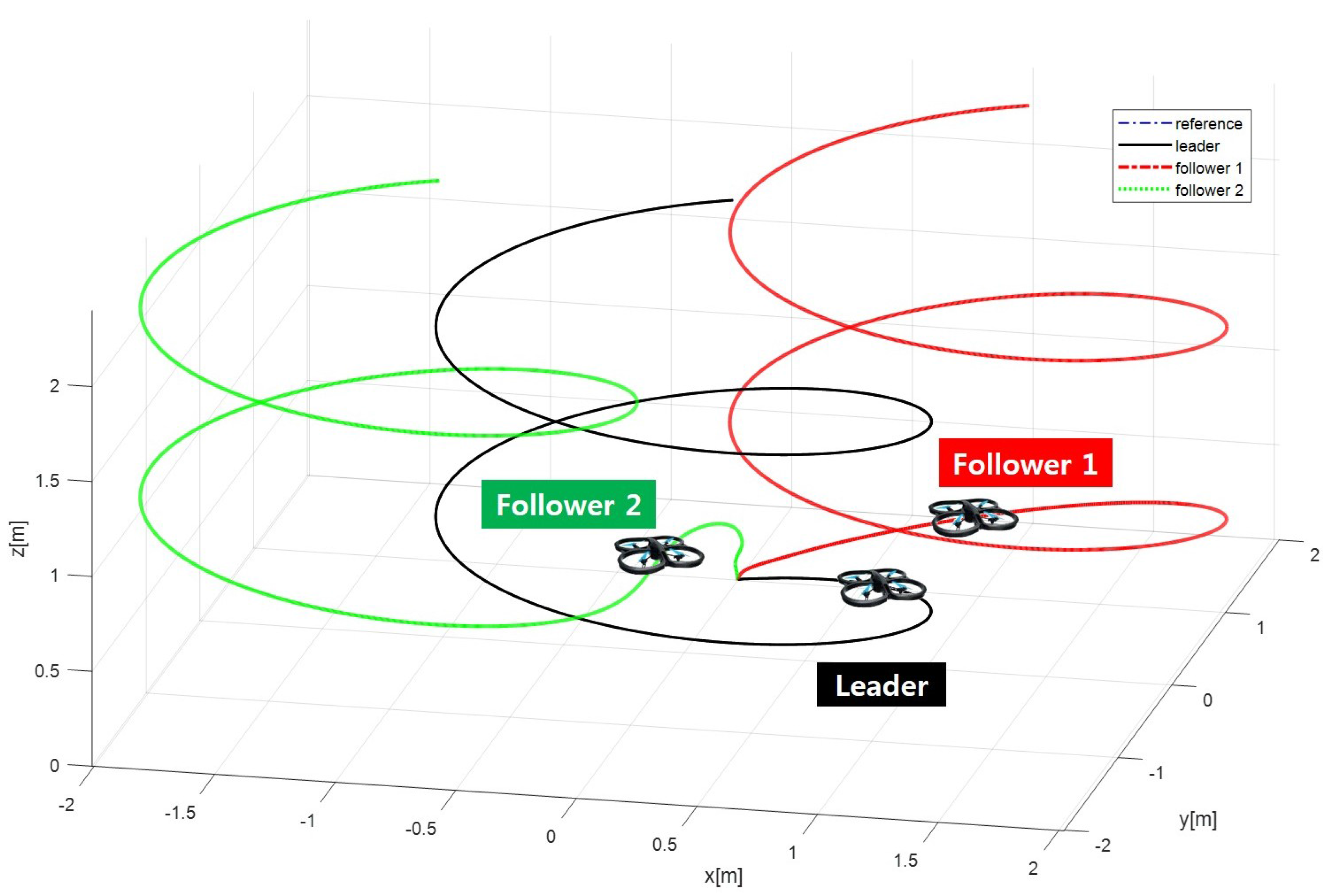
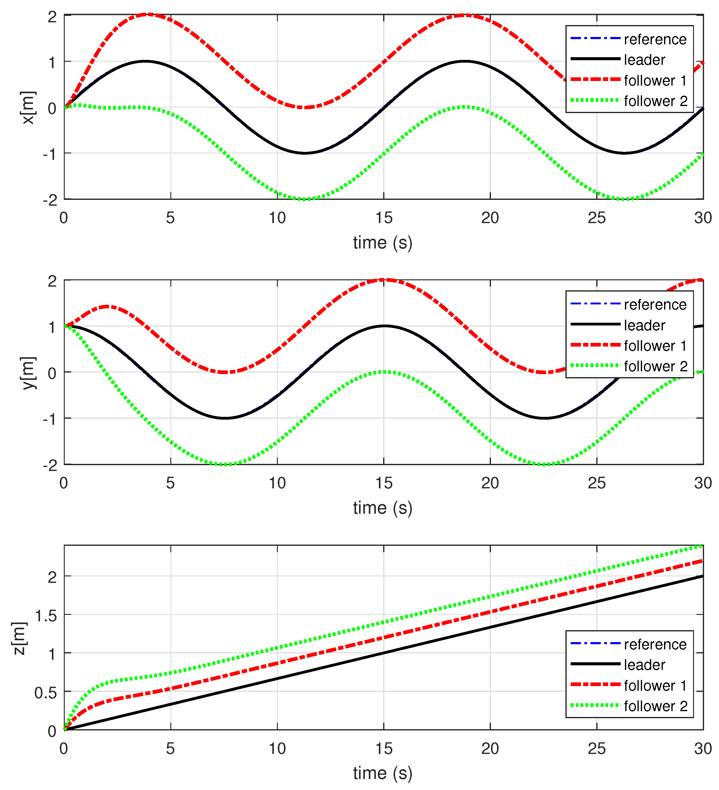
Figure 4 and Figure 5 show the simulation results obtained by applying the backstepping-based quadrotor formation control using the state transformation technique. As shown in Figure 4 and Figure 5, the initial position of the leader and follower quadrotors is = (0,1,0) (m), and the reference trajectory is set to the ascending 720-degree circular trajectory. From the simulation results, we can see that the leader tracks the predefined trajectory well, and the follower quadrotors maintain a constant distance from the leader quadrotor, as well as the formation shape.
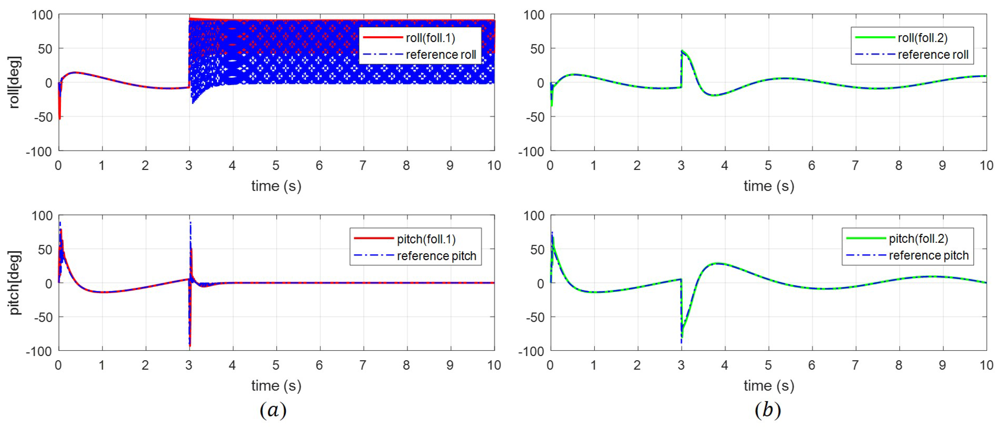
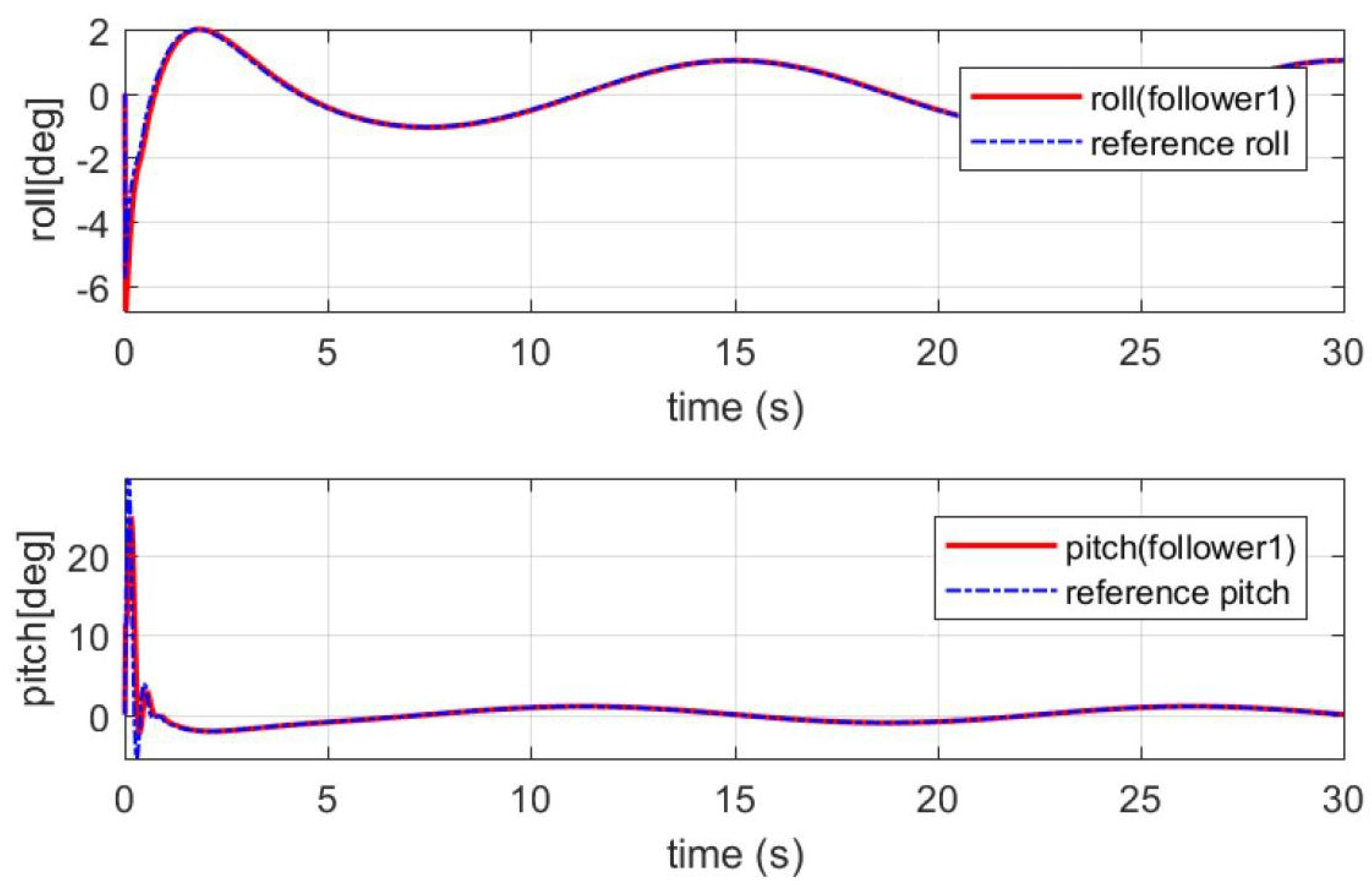
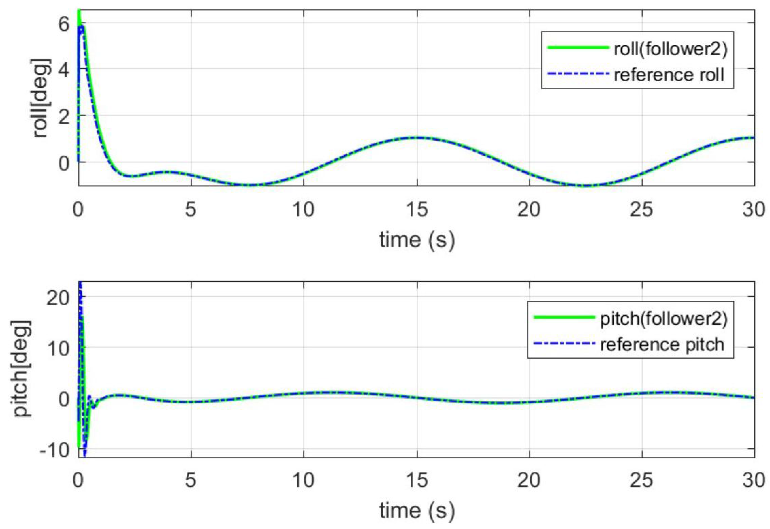
Figure 6 and Figure 7 show the simulation results for the attitude control of Followers 1 and 2, respectively. The initial state of the follower quadrotors is (rad), the current follower attitude angles track the reference attitude angles enabling the follower quadrotors to follow and maintain the set distance from the leader.
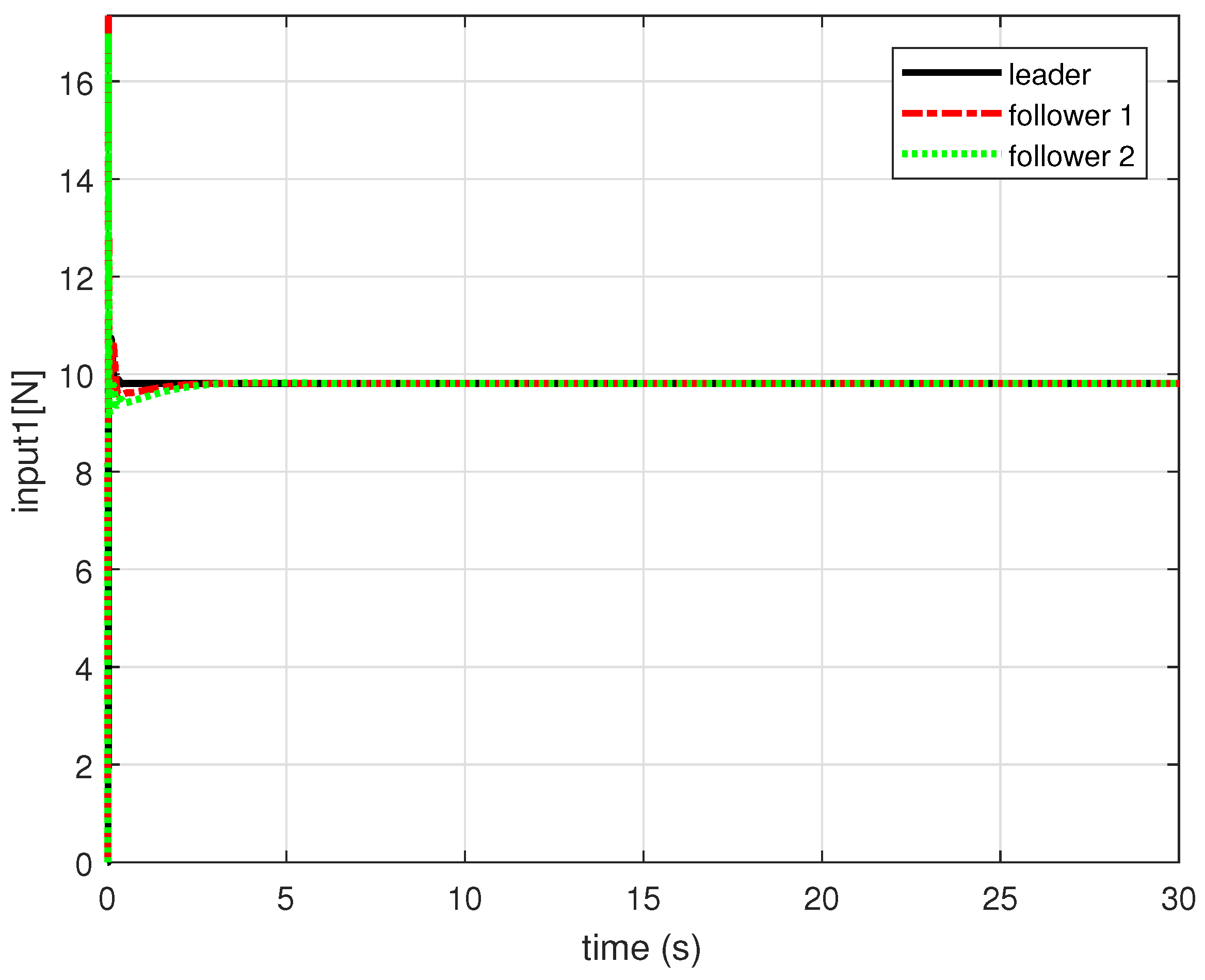
Figure 8 and Figure 9 show the altitude and attitude control inputs of the leader and follower quadrotors, respectively. As shown in the simulation result, the altitude control input is a positive value and close to about 9.8 N, which is the magnitude of gravity force. Furthermore, we can see that the size changes of inputs , and are within a reasonable range.
Figure 10, Figure 11, Figure 12 and Figure 13 show performance comparison simulations for tracking a circular trajectory at low speed ( s) and tracking a circular trajectory at high speed ( s) using the proposed control method and PID control method with the small angle assumption. In this simulation, we set the same ascending circular trajectory as before. We set the initial position of each follower and the leader to be equal to = (0,1,0) (m) and the desired relative distances between the follower and the leader to = (1,1,0.4) (m). In addition, for fair performance comparison, the feedback gain of PID controllers used in this simulation is selected by changing slightly based on the gain of PID controller used in [32]: these gains were tuned to ensure acceptable tracking performance considering reality with minimizing the overshoot and undershoot error signals.
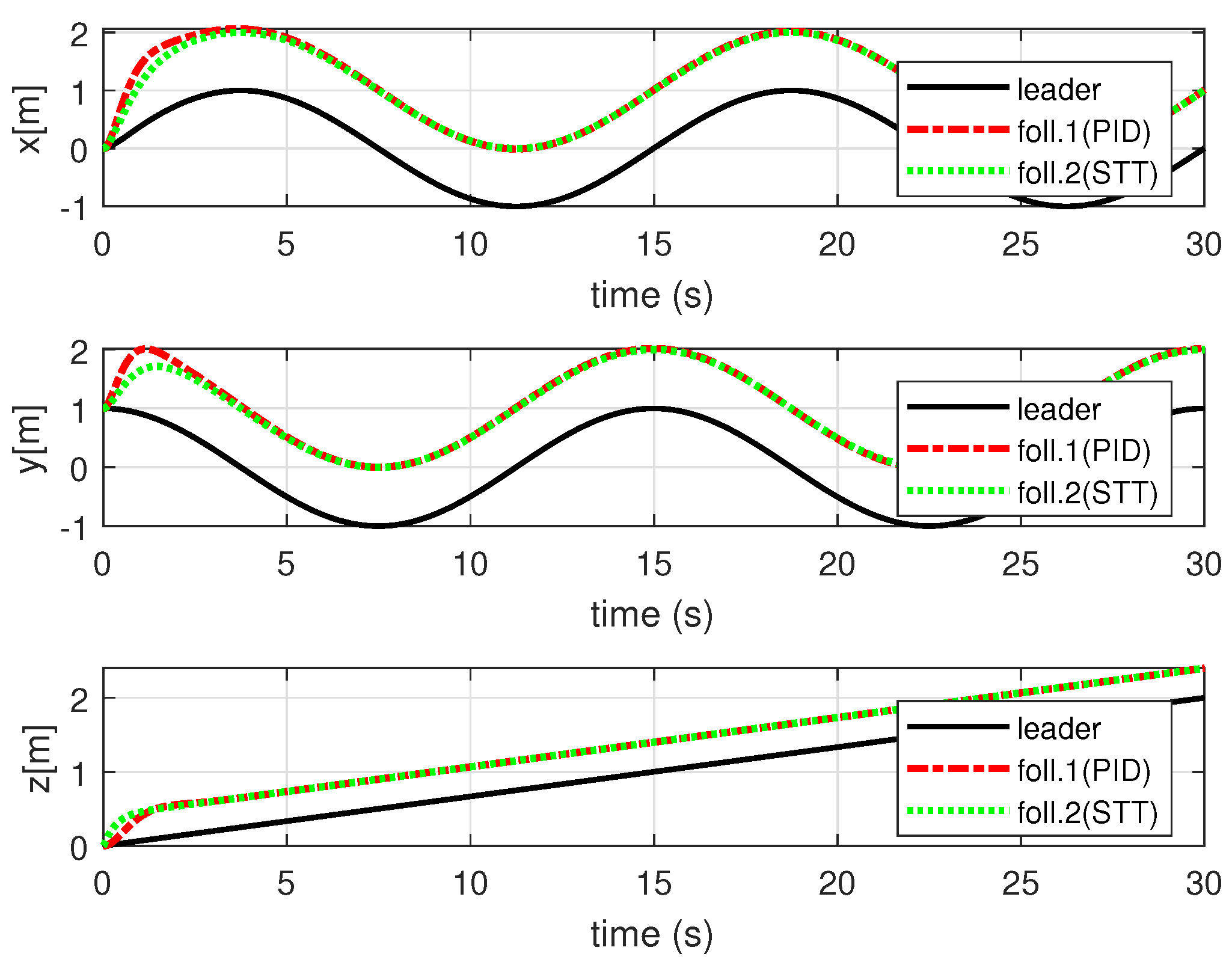
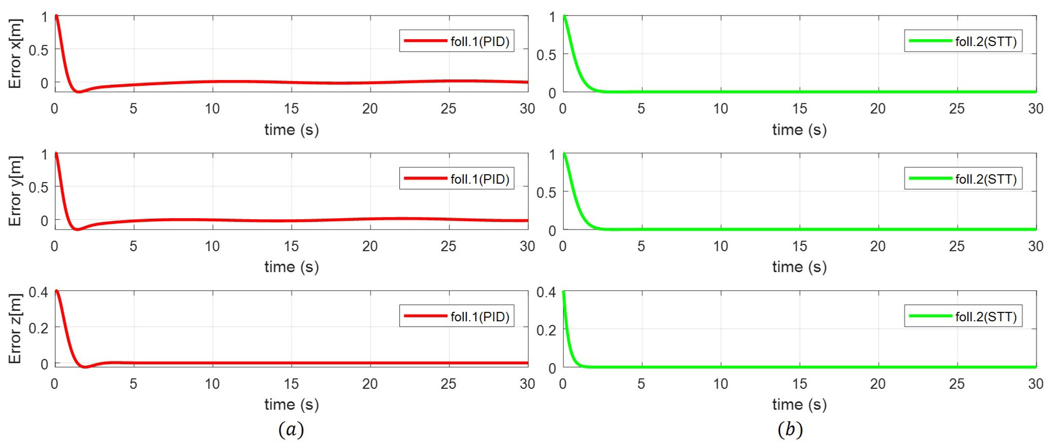
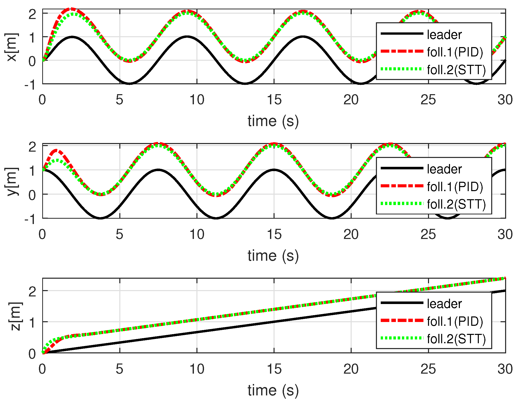
Figure 10 and Figure 11 show the simulation results for quadrotor to track a circular trajectory two times in 30 s. As shown in Figure 10 and Figure 11, there is no significant difference between two cases when the reference angles for the formation control are small. In this case, both the PID control method and the formation control method proposed in this paper show good performance of the formation control.
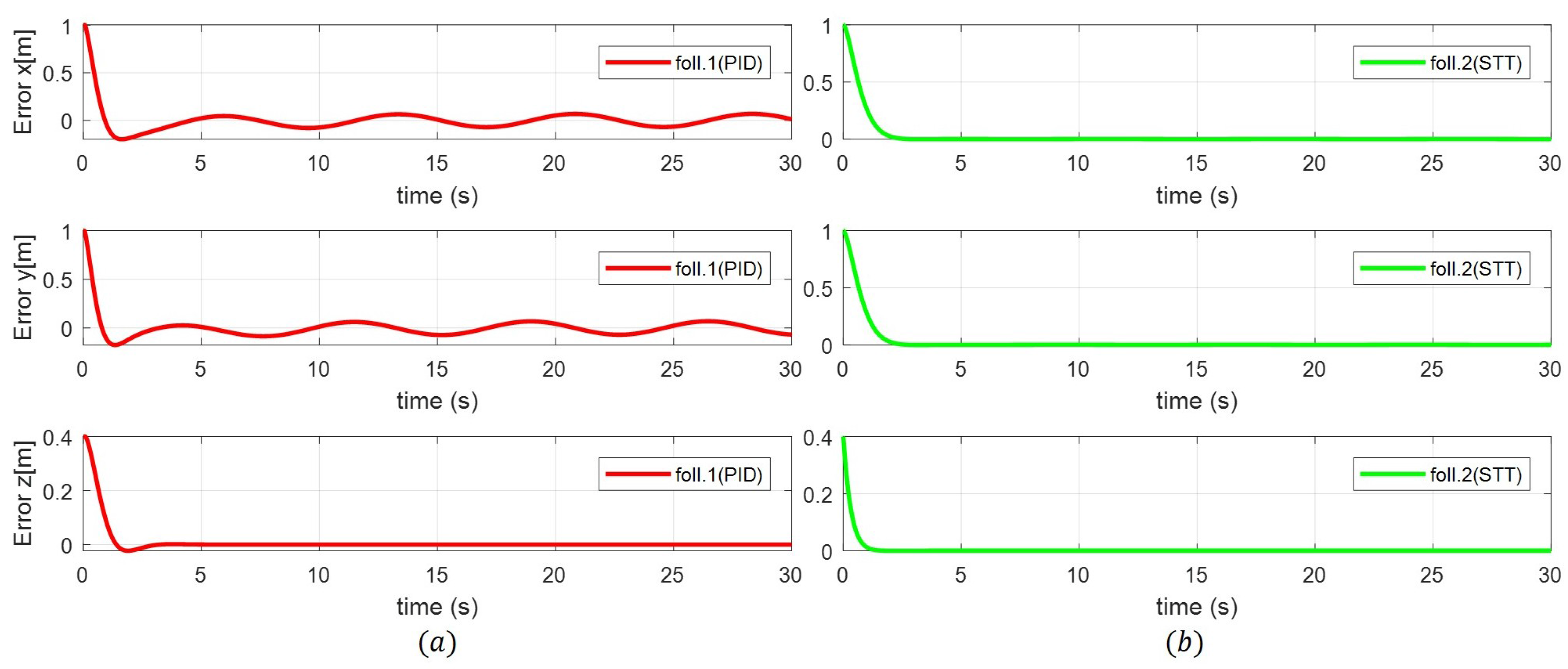
Figure 12 and Figure 13 show the simulation results for the quadrotor tracking the circular trajectory four times in 30 s. In this case, unlike the previous case, larger reference angles are required to track the circle trajectory faster. When the change of the attitude angle is large, in the case of deriving the reference angle using the PID control method applied to simplified dynamics with SAA, the formation control performance is degraded as shown in Figure 13a. As shown in Figure 13a, the formation errors for the x-, y- and z-axes do not converge completely to zero. On the other hand, when the reference angles for formation control are derived using the proposed state transformation technique, the formation errors for the x-, y- and z-axes converge completely to zero as shown in Figure 13b. The simulation results are shown in Figure 10, Figure 11, Figure 12 and Figure 13. Furthermore, if we set up more rotating trajectories within the same time, the formation cannot be maintained, and the states of follower quadrotors diverge when using the PID control method applied to the simplified dynamics with SAA.
Figure 14, Figure 15, Figure 16, Figure 17 and Figure 18 show performance comparison simulations for tracking a circular trajectory at low speed ( s) and tracking a circular trajectory at high speed ( s) using the proposed formation control method with the state transformation technique and backstepping-based formation control with SAA. The formation control problem covered in this simulation is the same as before, with the leader tracking the ascending circular trajectory followed by two follower quadrotors. For fair performance comparison, the conditions of each follower were the same. We set the initial position of each follower to = (0,1,0) (m) and the desired relative distances between the follower quadrotor and the leader to = (1,1,0.4) (m). Furthermore, the same backstepping control method was used to control the altitude, position and attitude of each follower, and the same feedback gain values were also used.
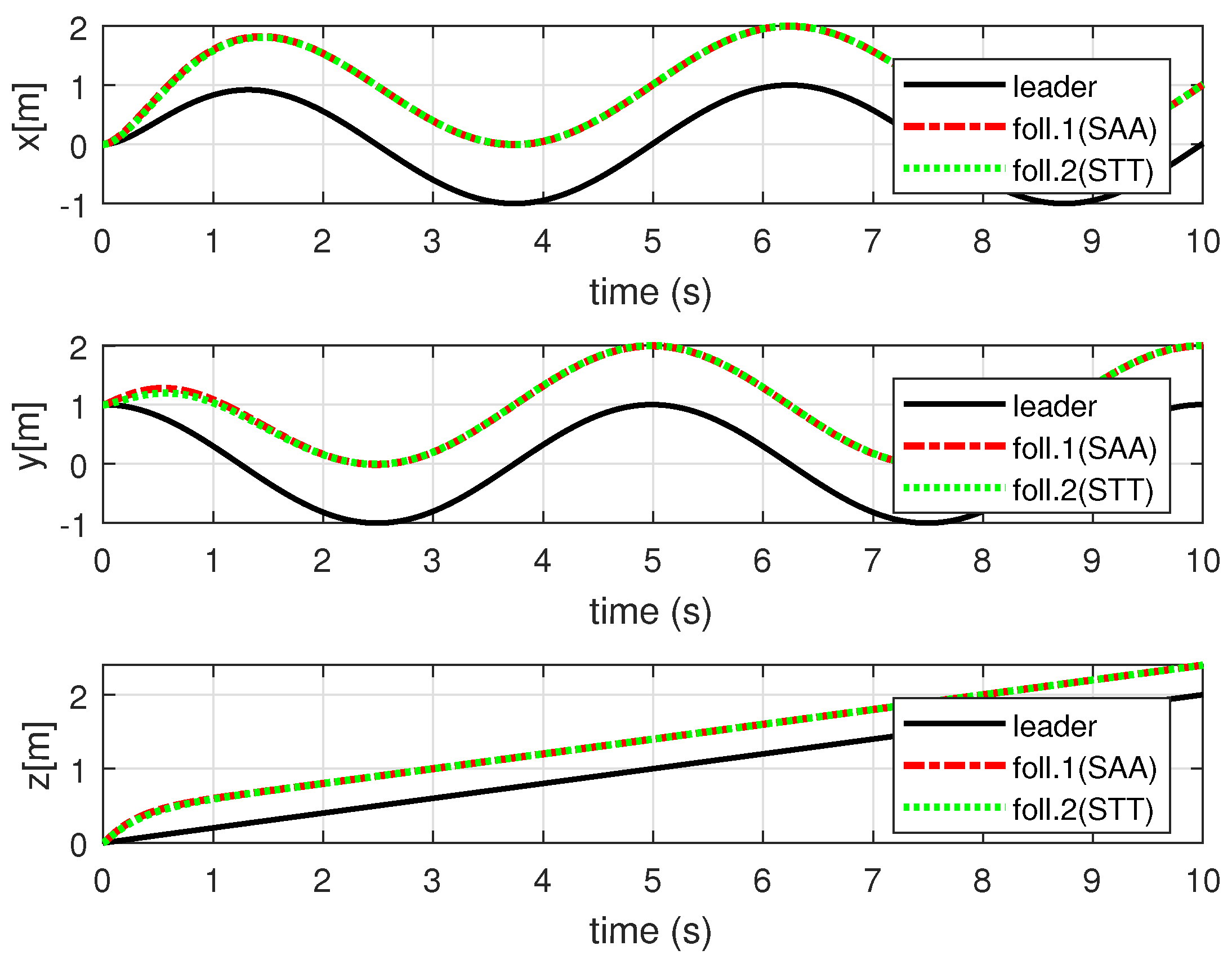
Figure 14 shows the result of the formation control using the state transformation technique proposed in this paper and the formation control using SAA. Simulation results for the x-, y- and z-axis errors in each case are shown in Figure 15a,b, respectively. As shown in Figure 14, Figure 15 and Figure 16, when the leader flies a 4 circular trajectory in 10 s, the large reference attitude angles are not required, and the follower quadrotors trail the leader in a circular motion pattern with small attitude angles (as shown in Figure 16). In this case, the proposed formation control using the state transformation technique and the conventional formation control using SAA show similar formation control performance.
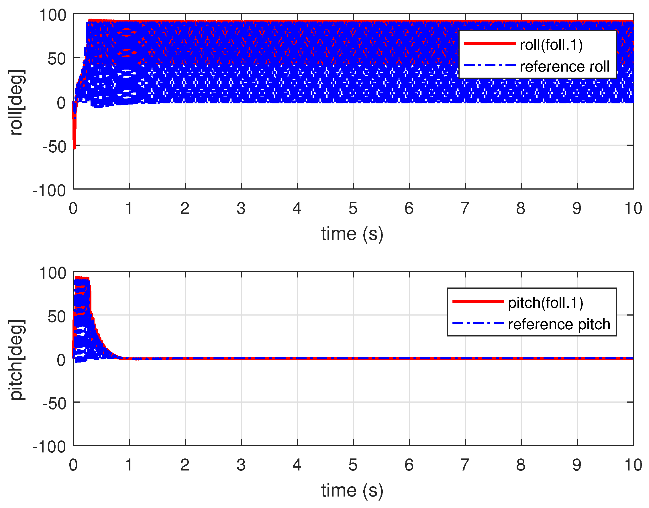
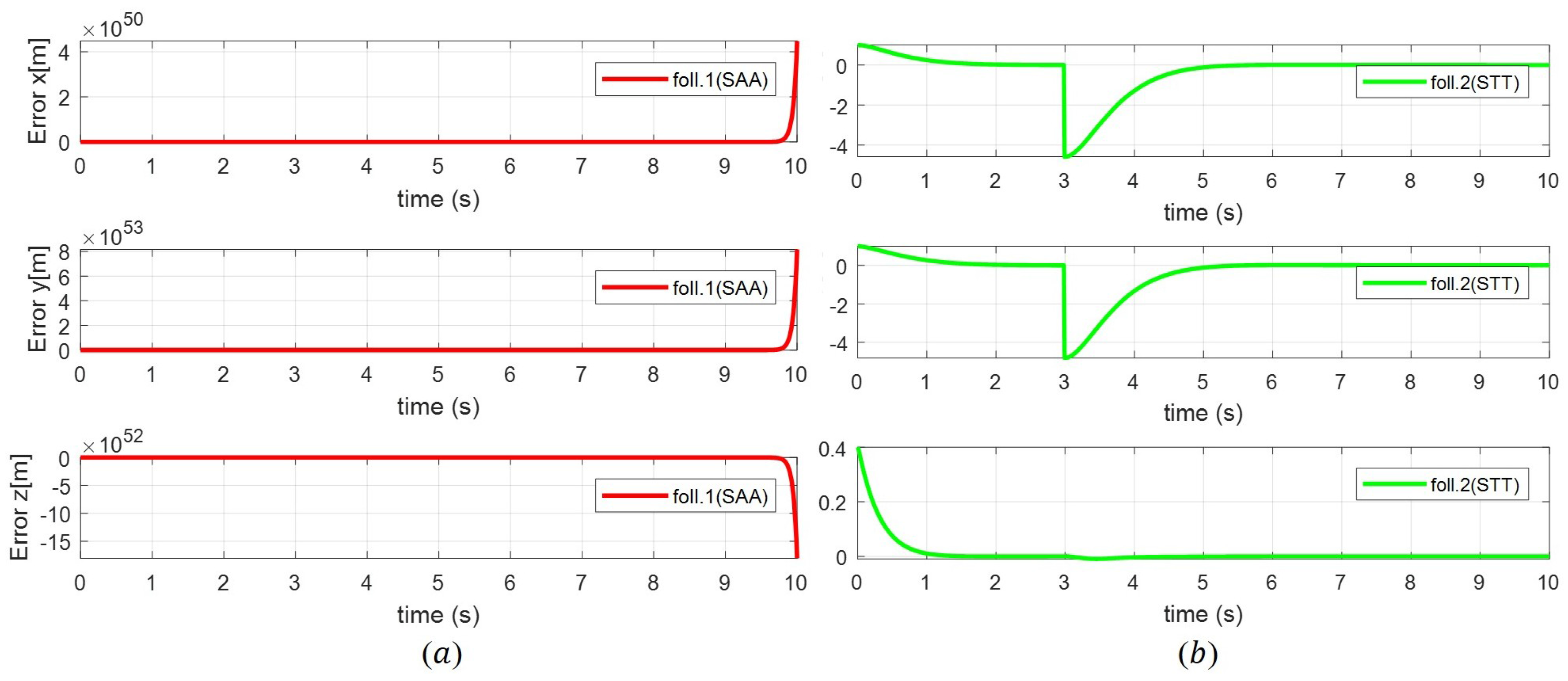
Next, we set the trajectory so that the quadrotor rotates three times in 10 s as shown in Figure 17, Figure 18, Figure 19 and Figure 20. In this case, as shown in Figure 18, larger reference attitude angles are required for faster rotation. As shown in Figure 17 and Figure 18, we can confirm that the proposed formation control using the state transformation technique allows the follower quadrotor to properly trail the leader.
However, as shown in Figure 19 and Figure 20, the general formation control using SAA does not. A fact, if we set the values of gain small, the quadrotor system does not diverge. However, if we set up more rotating trajectories within the same time, we can confirm that the follower quadrotor diverges like in Figure 19 and Figure 20 when we use the formation control with SAA.
We have carried out further simulations considering disturbance in order to demonstrate the superiority and effectiveness of the controller proposed in this paper. Quadrotors can experience disturbances such as wind during a flight. So, through the simulation considering disturbance, we can deal with the more practical environment. We can verify the effectiveness of the controller by looking at whether the proposed controller maintains good performance even with disturbance.
We compared the performance between the proposed formation control using the state transformation technique to derive the reference attitude angles and the method using SAA to derive the reference attitude angles in the same simulation conditions as Figure 17 and Figure 18. We set the disturbance environment that each follower quadrotor receives a force in each direction of x and y axis at 3 s as shown in Figure 21.
For disturbances below a certain size, both the case of using the small angle assumption and the case of using the state transformation technique show good tracking performance. However, if there is disturbance greater than a certain magnitude, in the case of using the small angle assumption, to maintain the formation, too large reference attitude angles are required, and as a result, the quadrotor system diverges. On the other hand, in the case of using the proposed backstepping formation controller with the state transformation technique, not too large reference attitude angles are required, and it can be confirmed that the original formation is maintained within about 2 s despite the presence of disturbance (see Figure 21 and Figure 22).
5. Conclusions
In this paper, we dealt with a backstepping-based quadrotor formation control using the state transformation technique. First, we derived the quadrotor dynamics using the Newton–Euler formulation. Then, we presented a backstepping-based quadrotor formation control using the state transformation technique. Furthermore, we derived the reference attitude angles for the formation control using the designed formation controller. Using the state transformation technique, it is possible to derive the reference attitude angles without the small angle assumption or simplified dynamics usually used. The stability analysis based on the Lyapunov theorem showed that the proposed formation control can realize a quadrotor formation error system that is asymptotically stabilized. Finally, from the simulation results, we verified that the proposed backstepping-based quadrotor formation control method using the state transformation technique has better performance than those of other formation control methods even with large angular variations and sudden disturbance.
Acknowledgments
This research was supported by the Basic Science Research Program through the National Research Foundation of Korea (NRF) funded by the Ministry of Science, ICT & Future Planning (No. 2015R1A2A2A01007545).
Author Contributions
All authors discussed the contents of the manuscript. Keunuk Lee contributed to the research idea and the framework of this study. Keunuk Lee and Yoonho Choi designed the backstepping-based formation controller using the state transformation technique. Jinbae Park contributed to the modeling of the quadrotor and the stability proof. Keunuk Lee performed the simulation and wrote the paper. All authors analyzed the results of this study.
Conflicts of Interest
The authors declare no conflict of interest.
References
- Sharma, R.K.; Ghose, D. Collision avoidance between UAV clusters using swarm intelligence techniques. Int. J. Syst. Sci. 2009, 40, 521–538. [Google Scholar] [CrossRef]
- Rinaldi, F.; Chiesa, S.; Quagliotti, F. Linear quadratic control for quadrotors UAVs dynamics and formation flight. J. Intell. Robot. Syst. 2013, 70, 203–220. [Google Scholar] [CrossRef]
- Mercado, D.A.; Castro, R.; Lozano, R. Quadrotors flight formation control using a leader-follower approach. In Proceedings of the 2013 European Control Conference (ECC), Zürich, Switzerland, 17–19 July 2013; pp. 3858–3863. [Google Scholar]
- Davidi, A.; Berman, N.; Arogeti, S. Formation flight using multiple integral backstepping controllers. In Proceedings of the 2011 IEEE 5th International Conference on Cybernetics and Intelligent Systems (CIS), Qingdao, China, 17–19 September 2011; pp. 317–322. [Google Scholar]
- Wu, F.; Chen, J.; Liang, Y. Leader-Follower Formation Control for Quadrotors. IOP Conf. Ser. Mater. Sci. Eng. 2017, 187, 1–8. [Google Scholar] [CrossRef]
- Guerrero, J.A.; Castillo, P.; Salazar, S.; Lozano, R. Mini Rotorcraft Flight Formation Control Using Bounded Inputs. J. Intell. Robot. Syst. 2012, 65, 175–186. [Google Scholar] [CrossRef]
- Kotov, K.Y.; Mal’tsev, A.S.; Nesterov, A.A.; Sobolev, M.A.; Yan, A.P. Decentralized control of quadrotors in a leader–follower formation. Optoelectron. Instrum. Data Process. 2017, 53, 21–25. [Google Scholar] [CrossRef]
- Roldão, V.; Cunha, R.; Cabecinhas, D.; Silvestre, C.; Oliveira, P. A leader-following trajectory generator with application to quadrotor formation flight. Robot. Auton. Syst. 2014, 62, 1597–1609. [Google Scholar] [CrossRef]
- Bayezit, I.; Fidan, B. Distributed cohesive motion control of flight vehicle formations. IEEE Trans. Ind. Electron. 2013, 60, 5763–5772. [Google Scholar] [CrossRef]
- Kushleyev, A.; Mellinger, D.; Kumar, V. Towards a swarm of agile micro quadrotors. Auton. Robot. 2012, 35, 287–300. [Google Scholar] [CrossRef]
- Abdessameud, A.; Tayebi, A. Formation control of VTOL unmanned aerial vehicles with communication delays. Automatica 2011, 47, 2383–2394. [Google Scholar] [CrossRef]
- Dong, X.; Yu, B.; Shi, Z.; Zhong, Y. Time-varying formation control for unmanned aerial vehicles: Theories and applications. IEEE Trans. Control Syst. Technol. 2015, 23, 340–348. [Google Scholar] [CrossRef]
- Guerrero, J.A.; Castillo, P.; Challal, Y. Quadrotors Formation Control: A Wireless Medium Access Aware Approach. J. Intell. Robot. Syst. 2013, 70, 221–231. [Google Scholar] [CrossRef]
- Wang, Y.; Wu, Q.; Wang, Y. Distributed cooperative control for multiple quadrotor systems via dynamic surface control. Nonlinear Dyn. 2014, 75, 513–527. [Google Scholar] [CrossRef]
- Defoort, M.; Floquet, T.; Kokosy, A.; Perruquetti, W. Sliding-Mode Formation Control for Cooperative Autonomous Mobile Robots. IEEE Trans. Ind. Electron. 2008, 55, 3944–3953. [Google Scholar] [CrossRef]
- Erginer, B.; Altug, E. Modeling and PD Control of a Quadrotor VTOL Vehicle. In Proceedings of the 2007 IEEE Intelligent Vehicles Symposium, Istanbul, Turkey, 13–15 June 2007; pp. 894–899. [Google Scholar]
- Oner, K.; Cetinsoy, E.; Unel, M.; Aksit, M.; Kandemir, I.; Gulez, K. Dynamic Model and Control of a New Quadrotor UAV with Tilt-wing Mechanism. IJMME 2008, 2, 12–17. [Google Scholar]
- Gong, X.; Hou, Z.C.; Zhao, C.J.; Bai, Y.; Tian, Y.T. Adaptive Backstepping Sliding Mode Trajectory Tracking Control for a Quadrotor. Int. J. Autom. Comput. 2012, 9, 555–560. [Google Scholar] [CrossRef]
- Huang, M.; Xian, B.; Diao, C.; Yang, K.; Feng, Y. Adaptive Tracking Control of Underactuated Quadrotor Unmanned Aerial Vehicles via Backstepping. In Proceedings of the 2010 American Control Conference, Baltimore, MD, USA, 30 June–2 July 2010; pp. 2076–2081. [Google Scholar]
- Bouabdallah, S.; Siegwart, R. Full control of a quadrotor. In Proceedings of the 2007 IEEE/RSJ International Conference on Intelligent Robots and Systems, San Diego, CA, USA, 29 October–2 November 2007; pp. 153–158. [Google Scholar]
- Das, A.; Lewis, F.; Subbarao, K. Backstepping Approach for Controlling a Quadrotor Using Lagrange Form Dynamics. J. Intell. Robot. Syst. 2009, 56, 127–151. [Google Scholar] [CrossRef]
- Raffo, G.V.; Ortega, M.G.; Rubio, F.R. Backstepping/Nonlinear H∞ Control for Path Tracking of a QuadRotor Unmanned Aerial Vehicle. In Proceedings of the 2008 American Control Conference, Seattle, DC, USA, 11–13 June 2008; pp. 3356–3361. [Google Scholar]
- Altug, E.; Ostrowski, J.P.; Mahony, R. Control of a Quadrotor Helicopter Using Visual Feedback. In Proceedings of the 2002 IEEE International Conference on Robotics & Automation, Washington, DC, USA, 11–15 May 2002; pp. 72–77. [Google Scholar]
- Mian, A.A.; Daobo, W. Modeling and Backstepping-based Nonlinear Control Strategy for a 6 DOF Quadrotor Helicopter. Chin. J. Aeronaut. 2008, 21, 261–268. [Google Scholar] [CrossRef]
- Heriberto, R.R.; Vicente, P.V.; Anand, S.O.; Octavio, G.S. Robust Backstepping Control Based on Integral Sliding Modes for Tracking of Quadrotors. J. Intell. Robot. Syst. 2014, 73, 51–66. [Google Scholar]
- Madani, T.; Benallegue, A. Sliding Mode Observer and Backstepping Control for a Quadrotor Unmanned Aerial Vehicles. In Proceedings of the 2007 American Control Conference, New York, NY, USA, 11–13 July 2007; pp. 5887–5892. [Google Scholar]
- Zuo, Z. Trajectory tracking control design with command-filtered compensation for a quadrotor. IET Control Theory Appl. 2010, 4, 2343–2355. [Google Scholar] [CrossRef]
- Gong, X.; Bai, Y.; Peng, C.; Zhao, C.; Tian, Y. Trajectory Tracking Control of a Quad-rotor UAV Based on Command Filtered Backstepping. In Proceedings of the 2012 Third International Conference on Intelligent Control and Information Processing, Dalian, China, 15–17 July 2012; pp. 179–184. [Google Scholar]
- Lee, D.W.; Kim, H.J.; Sastry, S. Feedback Linearization vs. Adaptive Sliding Mode Control for a Quadrotor Helicopter. Int. J. Control Autom. Syst. 2009, 7, 419–428. [Google Scholar] [CrossRef]
- Xie, H.; Lynch, A.F. Input Saturated Visual Servoing for Unmanned Aerial Vehicles. IEEE/ASME Trans. Mech. 2017, 22, 952–960. [Google Scholar] [CrossRef]
- Khalil, H. Nonlinear Systems, 3rd ed.; Prentice Hall: New York, NY, USA, 2002. [Google Scholar]
- Bouabdallah, S.; Noth, A.; Siegwart, R. PID vs. LQ control techniques applied to an indoor micro quadrotor. In Proceedings of the 2004 IEEE/RSJ International Conference on Intelligent Robots and Systems, Sendai, Japan, 28 September–2 October 2004; pp. 2451–2456. [Google Scholar]
Figure 1.
The generalized coordinates and thrusts of a quadrotor.
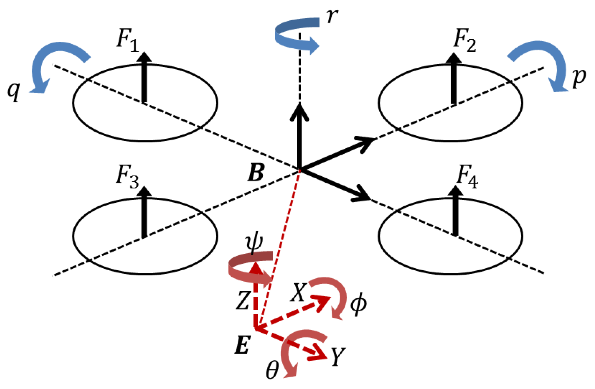
Figure 2.
The proposed formation control system block diagram.

Figure 3.
Leader follower structure for the formation of quadrotors.

Figure 4.
The simulation result for the formation control of quadrotors in three dimensions.

Figure 5.
The simulation result for the formation control of quadrotors in each of the three axis: The solid line indicates the trajectory of leader quadrotor, and the dashed lines are the trajectories of each follower quadrotor.
Figure 5.
The simulation result for the formation control of quadrotors in each of the three axis: The solid line indicates the trajectory of leader quadrotor, and the dashed lines are the trajectories of each follower quadrotor.

Figure 6.
The reference angles of the first follower quadrotor for the proposed formation control: the dashed line indicates the reference attitude angles that enable the quadrotor to converge to the desired formation, and the solid line is the result of the simulation about attitude responses of the first follower quadrotor.

Figure 7.
The reference angles of the second follower quadrotor for the proposed formation control: the meanings of the dashed line and the solid line are the same as in Figure 6.
Figure 7.
The reference angles of the second follower quadrotor for the proposed formation control: the meanings of the dashed line and the solid line are the same as in Figure 6.

Figure 8.
The control input for the altitude of the leader and follower quadrotors.

Figure 9.
The control inputs for the attitude of the leader and follower quadrotors.
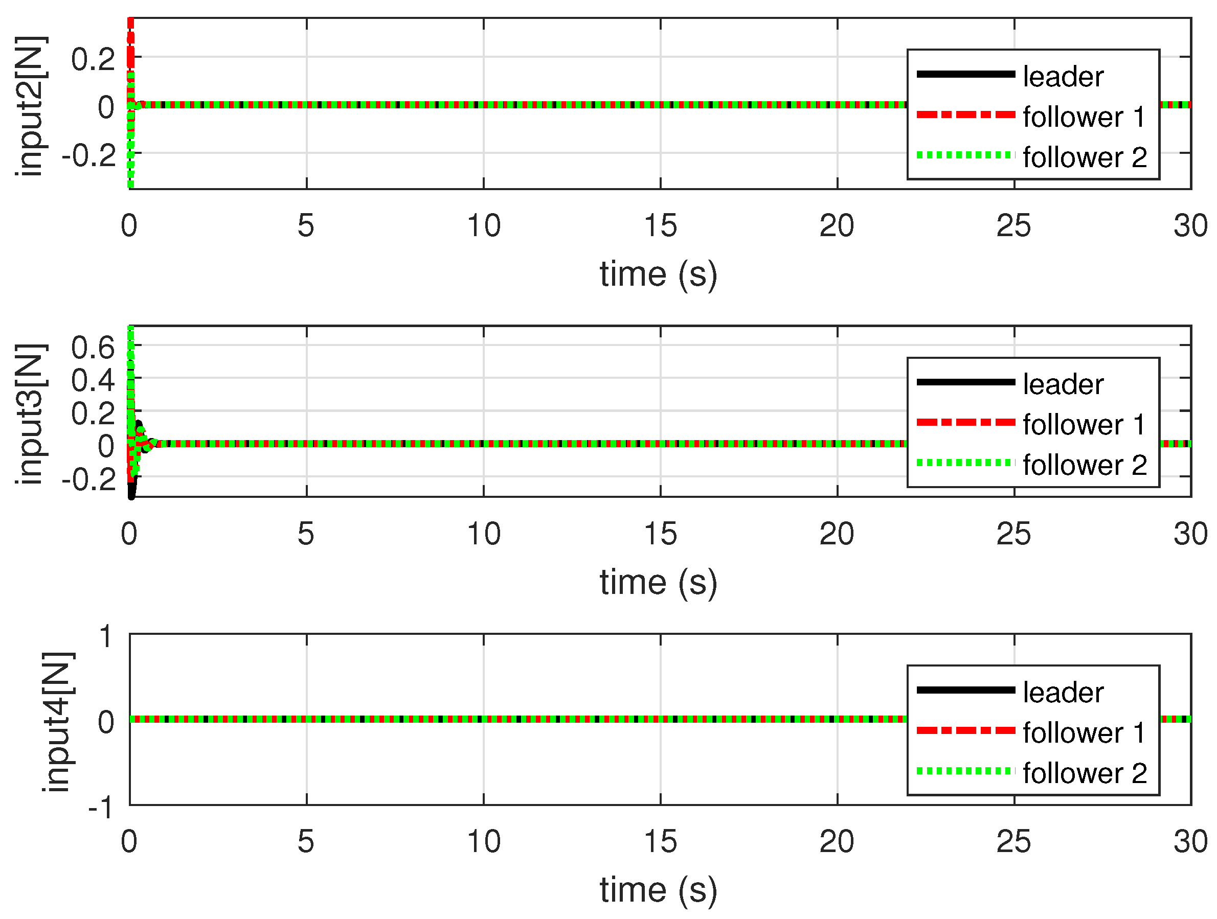
Figure 10.
The results of the comparison simulation for the formation control of quadrotors about the 4 circular trajectory: The red dashed line is the result of the formation control using the PID control method, and the green dashed line is the result of the formation control using the proposed formation control method with the state transformation technique (STT).

Figure 11.
The formation errors for each of the three axis about the 4 circular trajectory: (a) PID control method; (b) formation control method proposed in this paper.
Figure 11.
The formation errors for each of the three axis about the 4 circular trajectory: (a) PID control method; (b) formation control method proposed in this paper.

Figure 12.
The results of the comparison simulation for the formation control of quadrotors about the 8 circular trajectory: the red dashed line is the result of the formation control using the PID control method, and the green dashed line is the result of the formation control using the proposed formation control method with the state transformation technique (STT).

Figure 13.
The formation errors for each of the three axis about the 8 circular trajectory: (a) PID control method; (b) proposed formation control method in this paper.
Figure 13.
The formation errors for each of the three axis about the 8 circular trajectory: (a) PID control method; (b) proposed formation control method in this paper.

Figure 14.
The results of the comparison simulation for the formation control of quadrotors about the 4 circular trajectory: the red dashed line is the result of the backstepping-based formation control with small angle assumption (SAA), and the green dashed line is the result of the proposed formation control with the state transformation technique (STT).

Figure 15.
The formation errors for each of the three axis about the 4 circular trajectory: (a) backstepping-based formation control with SAA; (b) proposed formation control with the state transformation technique (STT).
Figure 15.
The formation errors for each of the three axis about the 4 circular trajectory: (a) backstepping-based formation control with SAA; (b) proposed formation control with the state transformation technique (STT).

Figure 16.
The reference angles of the follower quadrotors for the formation control about the 4 circular trajectory: the dashed line indicates the reference attitude angles that enable the quadrotor to converge to the desired formation, and the solid line is the result of the simulation about attitude responses of the follower quadrotors. (a) Backstepping-based formation control with SAA; (b) proposed formation control with the state transformation technique (STT).
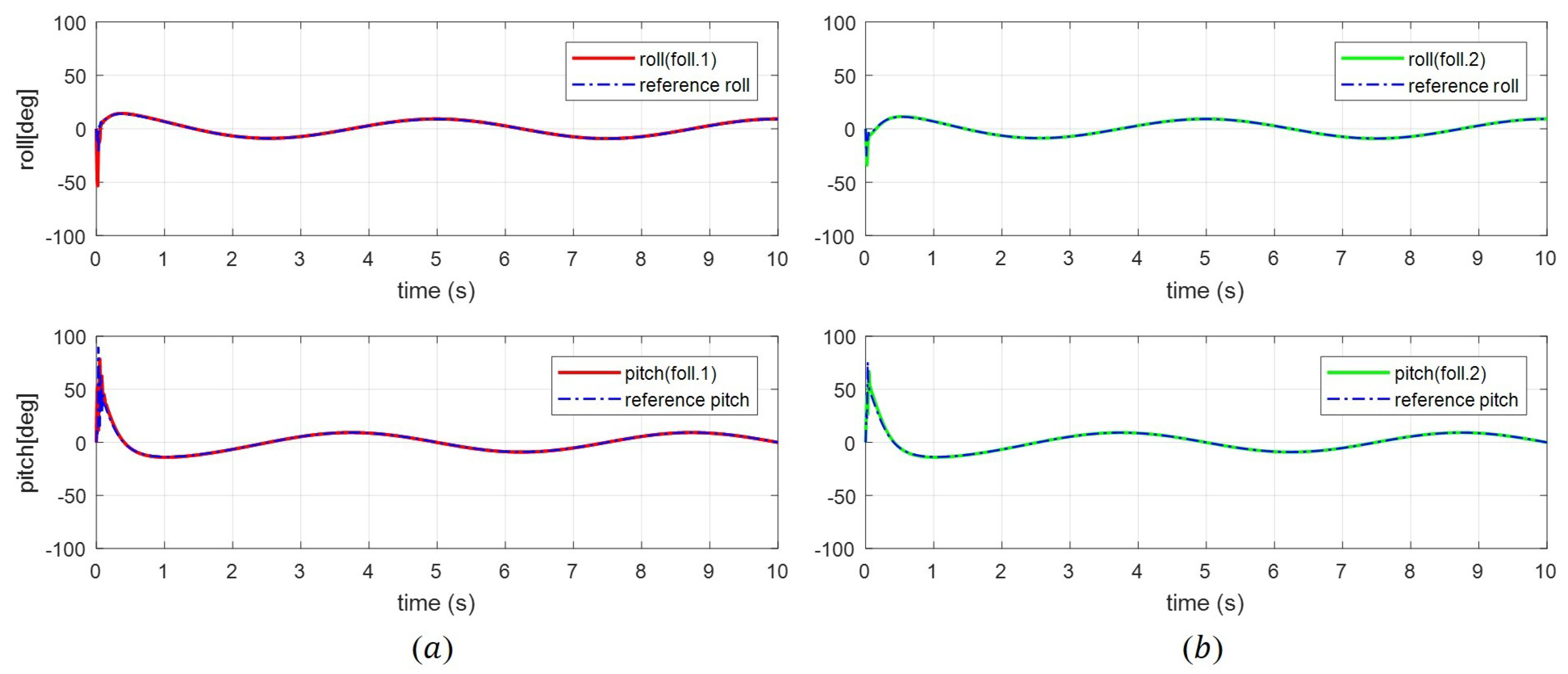
Figure 17.
The results of the comparison simulation for the formation control of the second follower quadrotors about the 6 circular trajectory: the solid line indicates the results of leader quadrotor; the green dashed line is the result of the proposed formation control with the state transformation technique (STT).
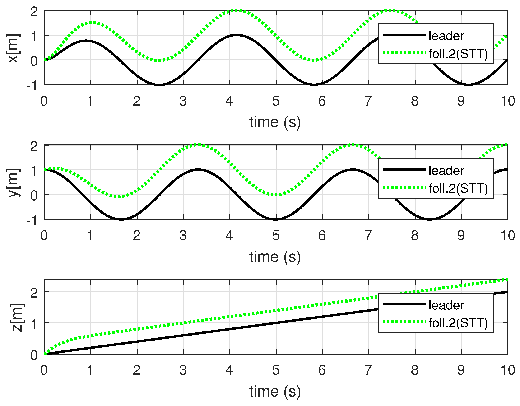
Figure 18.
The reference angles of the second follower quadrotors for the formation control about the 6 circular trajectory: the dashed line indicates the reference attitude angles that enable the second follower quadrotor to converge to the desired formation, and the solid line is the result of the simulation about attitude responses of the second follower quadrotors.
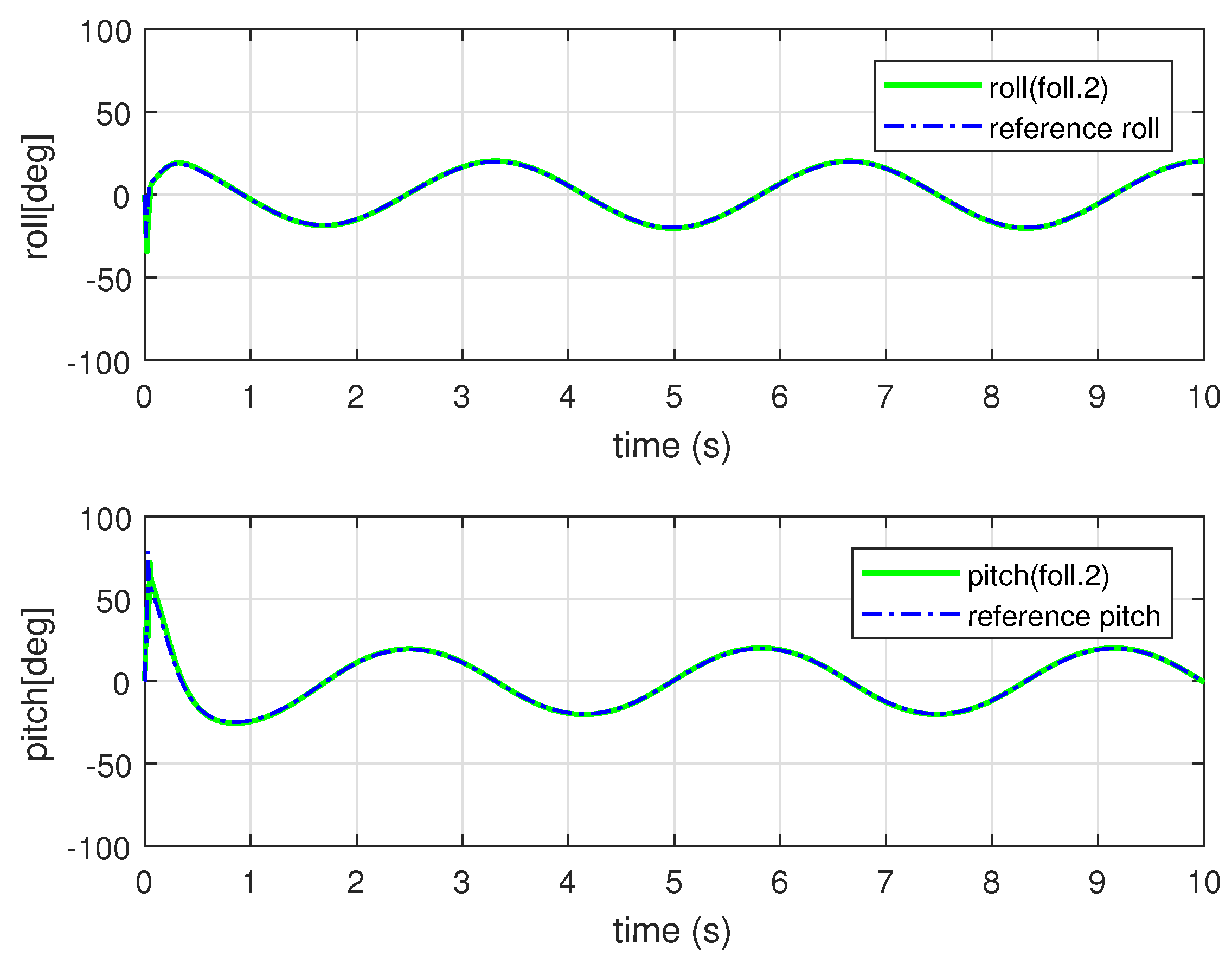
Figure 19.
The results of the comparison simulation for the formation control of the first follower quadrotors about the 6 circular trajectory: the solid line indicates the results of the leader quadrotor; the red dashed line is the result of the backstepping-based formation control with SAA.
Figure 19.
The results of the comparison simulation for the formation control of the first follower quadrotors about the 6 circular trajectory: the solid line indicates the results of the leader quadrotor; the red dashed line is the result of the backstepping-based formation control with SAA.
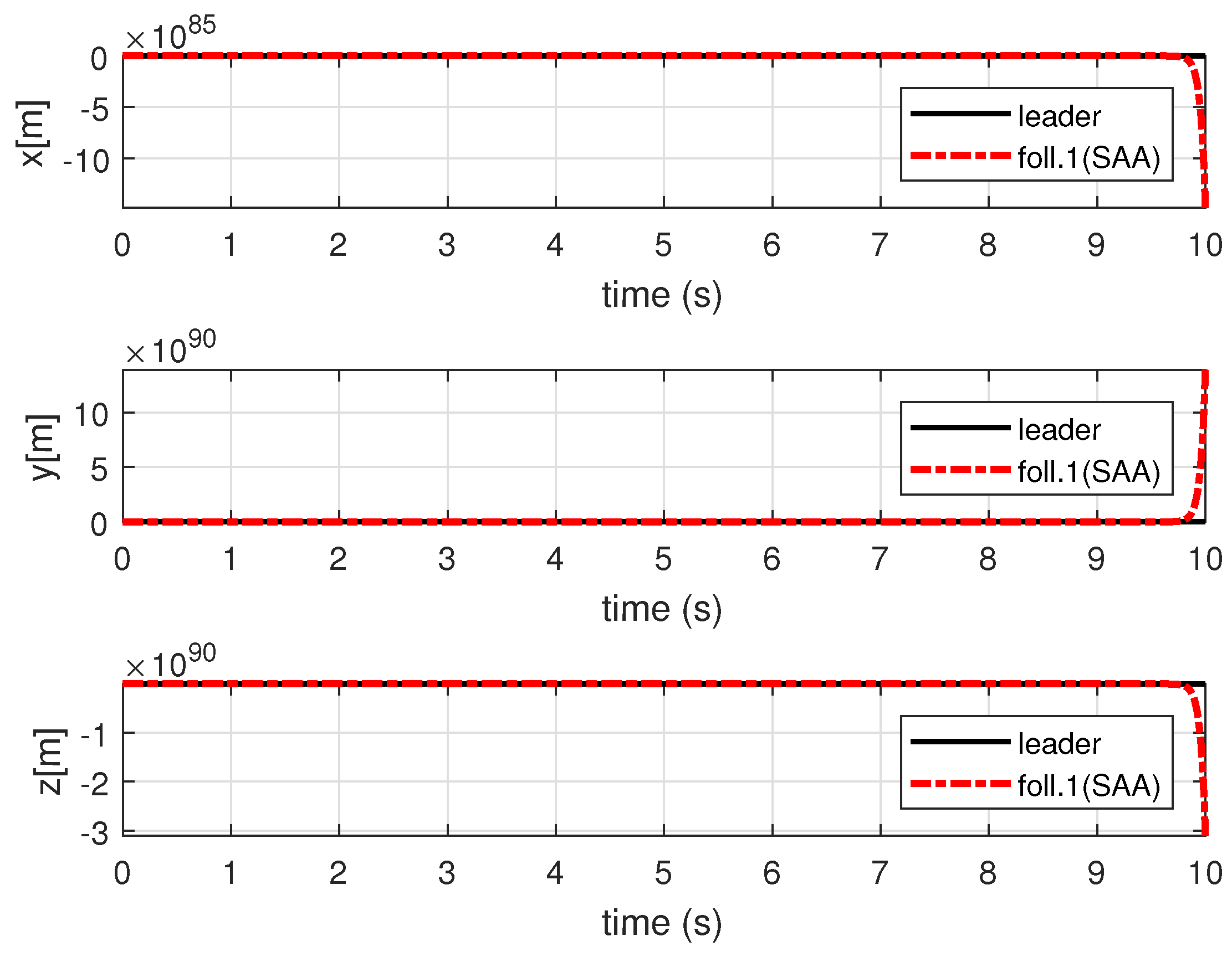
Figure 20.
The reference angles of the first follower quadrotors for the formation control about the 6 circular trajectory: The dashed line indicates the reference attitude angles that enable the first follower quadrotor to converge to the desired formation, and the solid line is the result of the simulation about attitude responses of the first follower quadrotors.

Figure 21.
The formation errors with disturbance: (a) backstepping-based formation control with SAA; (b) proposed formation control with the state transformation technique.
Figure 21.
The formation errors with disturbance: (a) backstepping-based formation control with SAA; (b) proposed formation control with the state transformation technique.

Figure 22.
The reference attitude angles with disturbance: (a) backstepping-based formation control with SAA; (b) proposed formation control with the state transformation technique.
Figure 22.
The reference attitude angles with disturbance: (a) backstepping-based formation control with SAA; (b) proposed formation control with the state transformation technique.

Table 1.
The model parameters for the dynamics of a quadrotor.
| Parameters | Value (Unit) |
|---|---|
| m | 1.0 (kg) |
| g | 9.806 (m/s) |
| 2.3 × 10 (kg · m) | |
| 2.3 × 10 (kg · m) | |
| 5.09 × 10 (kg · m) | |
| J | 6.5 × 10 (kg · m) |
© 2017 by the authors. Licensee MDPI, Basel, Switzerland. This article is an open access article distributed under the terms and conditions of the Creative Commons Attribution (CC BY) license (http://creativecommons.org/licenses/by/4.0/).
Share and Cite
MDPI and ACS Style
Lee, K.U.; Choi, Y.H.; Park, J.B. Backstepping Based Formation Control of Quadrotors with the State Transformation Technique. Appl. Sci. 2017, 7, 1170. https://doi.org/10.3390/app7111170
AMA Style
Lee KU, Choi YH, Park JB. Backstepping Based Formation Control of Quadrotors with the State Transformation Technique. Applied Sciences. 2017; 7(11):1170. https://doi.org/10.3390/app7111170
Chicago/Turabian StyleLee, Keun Uk, Yoon Ho Choi, and Jin Bae Park. 2017. "Backstepping Based Formation Control of Quadrotors with the State Transformation Technique" Applied Sciences 7, no. 11: 1170. https://doi.org/10.3390/app7111170
Note that from the first issue of 2016, this journal uses article numbers instead of page numbers. See further details here.