Closed Form Solutions for Thermal Buckling of Functionally Graded Rectangular Thin Plates


Institute of Solid Mechanics, Beihang University, Beijing 100191, China
*
Author to whom correspondence should be addressed.
Appl. Sci. 2017, 7(12), 1256; https://doi.org/10.3390/app7121256
Submission received: 31 October 2017
/
Revised: 27 November 2017
/
Accepted: 30 November 2017
/
Published: 3 December 2017
(This article belongs to the Special Issue Functionally Graded Material (FGM) and Functionally Graded Carbon Nanotube (FG-CNT) Reinforced Composites)
Abstract
:This work concerns the critical buckling temperature of functionally graded rectangular thin plates; the properties of functionally graded material vary continuously in accordance with the power law of thickness z. Closed form solutions for the critical thermal parameter are obtained for the plate with the following boundary condition combinations: simply supported, clamped and guided edges, under uniform, linear and nonlinear temperature fields via the separation-of-variable method. Furthermore, a new method is proposed to determine the critical buckling temperature from the critical thermal parameter. The present results coincide well with those in the literature, verifying the correctness of the present method. The influences of the length–thickness ratio, length–width ratio, power law index and initial temperature on critical buckling temperature are investigated.
1. Introduction
Designable Functionally Graded Materials (FGMs) are increasingly widely used in the aerospace, nuclear, and ship industries and other various industry departments, especially in thermal environments with ultra-high temperatures and a large temperature gradient. FGMs were proposed as thermal barrier materials by Japanese scientist Koizumi [1,2] to solve many problems in the new generation of aerospace airplane thermal protection systems. The volume content of each material in FGMs is continuously distributed in the spatial position on the macroscopic scale, and the physical properties change smoothly, so that the stress concentration of FGMs can be better avoided or reduced.
Since FGMs usually work in extremely high temperature environments, in order to ensure structural stability, the critical buckling temperature of FGM structures is very important in theory and application. Many researchers have studied the thermal buckling of FGM plates based on different theories in the past two decades.
Javaheri and Eslami [3] developed closed form solutions for the thermal buckling of simply supported FGM thin plates based on the Classical thin Plate Theory (CPT). Shariat and Eslami [4] obtained closed form solutions for the thermal buckling of simply supported imperfect FGM thin plates. Kiani et al. [5] investigated the critical buckling temperature of fully clamped FGM thin plates resting on elastic foundations; they used the Bubnov–Galerkin Solution (BGS), Power Series Solution (PSS) and Semi-Levy Solution (SLS) respectively to represent the lateral displacement which cannot be obtained by the Navier solution, and compared the solutions using these different approaches. Chu et al. [6] studied the critical buckling load and buckling model of FGM thin plate with in-plane material inhomogeneity by using radial basis function, but the thermal environment was not taken into account in their work.
Shear deformation plays a more prominent role for thick plates, so shear deformation theories are more accurate than CPT in this case. Wu [7] and Bouazza et al. [8] obtained a closed form solution for thermal buckling of simply supported FGM thick plates based on the first-order shear deformation theory (FSDT), and compared the results with those of CPT. Shariat and Eslami [9] developed closed form solutions for thermal buckling of imperfect simply supported FGM thick plates based on FSDT. Lee et al. [10] obtained a finite element solution for the critical buckling temperature based on neutral surface and FSDT. Park and Kim [11] presented thermal postbuckling and vibration analyses based on FSDT by using the nonlinear finite element method. Cong and Duc [12] studied the thermal stability of eccentrically stiffened sigmoid FGM thick plate with metal–ceramic–metal layers by the Galerkin method based on FSDT.
There are also some researches based on high-order shear deformation theories. Javaheri and Eslami [13] developed closed form solutions for thermal buckling of simply supported FGM thick plates based on the third-order shear deformation theory (TSDT). Najafizadeh and Heydari [14] investigated the critical buckling temperature of clamped FGM circular thick plates based on TSDT, and compared it with results based on CPT and FSDT. Matsunaga [15] investigated the critical buckling temperature of simply supported FGM thick plates based on the 2D higher-order deformation theory that he developed, and compared the results with CPT and other lower-order shear deformation theories such as FSDT and TSDT. Zenkour and Mashat [16] studied thermal buckling of simply supported FGM thick plates based on sinusoidal shear deformation plate theory (SPT) and obtained closed form solutions.
Some researchers have used three-dimensional linear elasticity theory to analyze the thermal buckling of FGM plates. Na and Kim [17] studied the critical buckling temperature of FGM plates with various boundary conditions under uniform, linear and sinusoidal temperature fields by establishing the finite element model via three-dimensional linear elasticity theory. Subsequently, Na and Kim [18] improved their previous work and studied the thermal buckling of FGM composite structures. Malekzadeh [19] investigated the thermal buckling of FGM arbitrary straight-sided quadrilateral plates via the differential quadrature method (DQM) based on three-dimensional linear elasticity theory. Asemi et al. [20] investigated buckling of functionally graded plates under biaxial compression, shear, tension-compression, and shear-compression load conditions by establishing a full compatible three-dimensional elasticity element, but they didn’t consider the thermal environment in their work. A review paper of various modeling techniques and solution methods in thermal analysis of FGM plates was also published [21].
From the above reviews, it can be seen that closed form solutions for thermal buckling of FGM plates are only available for a few boundary conditions such as fully simply supported parallel edges. Furthermore, there is currently no literature on the closed form solution for the critical buckling temperature of FGM thin plates for other boundary conditions. Furthermore, closed form solutions can play a reference role to study the convergence and precision of various numerical methods and serve the purpose of parametric designs of structures.
In the context of closed form solutions for the critical thermal parameter of simply supported FGM rectangular thin plates, guide and clamp boundary conditions are obtained via the separation-of-variable method. A novel method is presented to determine the critical buckling temperature from the critical thermal parameter. It is assumed that the FGM properties follow the power law distribution in the thickness direction. Two types of FGM thin plates and uniform, linear and nonlinear temperature fields are taken into account. The influences of the length–thickness ratio, length–width ratio, power law index and initial temperature on the critical buckling temperature are investigated in detail.
2. Governing Equation of Thermal Buckling
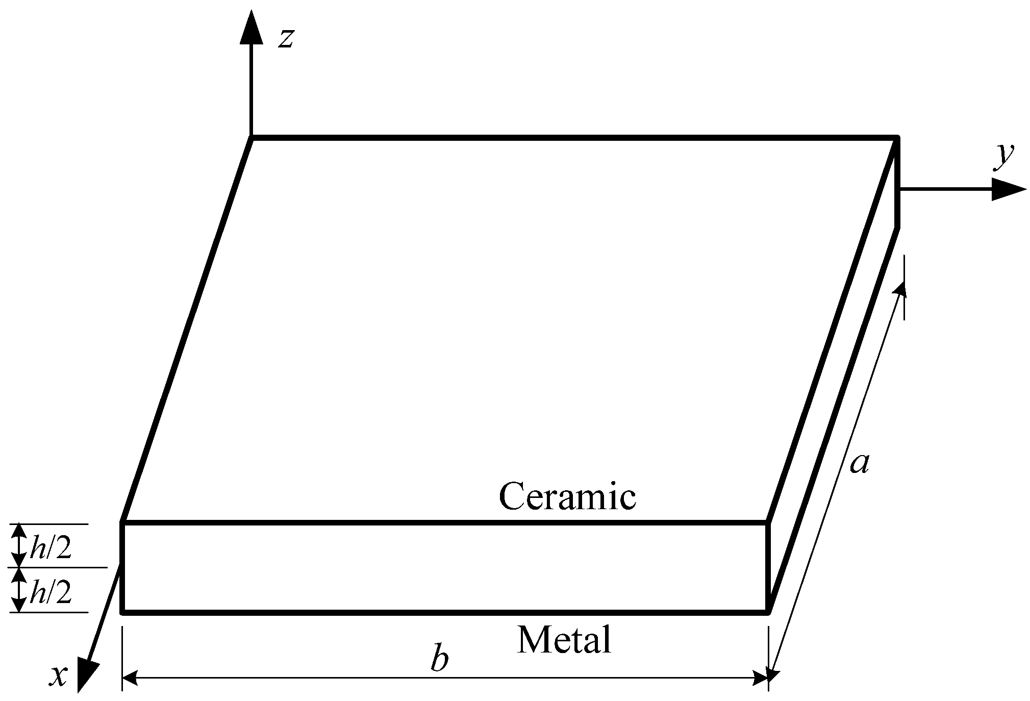
In this work, the FGM rectangular plate of length a, width b and thickness h is investigated as shown in Figure 1.
CPT is used with the following displacement fields
where u0 and v0 are the in-plane displacements on the midplane of the plate along the x and y direction, respectively; w is the midplane deflection. The strains associated with the displacement fields in Equation (1) are
The constitutive relation for the FGM plate subjected to thermo-mechanical loadings is
The stress resultants can be written as
Substituting Equations (1)–(3) into Equation (4) yields
where
From Equation (5), it can be seen that the in-plane loading and bending of the plate couple together because there is in-plane stretching in the geometrical midplane due to the materials’ asymmetry with respect to the midplane. However, the coupling can be eliminated by choosing the neutral surface instead of the geometrical midplane as a reference surface in which there are no in-plane displacements [22] (p. 1091).
The in-plane displacements of the midplane can be expressed as
where z0 is the distance between the geometrical midplane and the neutral surface. Substituting Equation (7) into Equation (5) yields
From Equation (8), it can be seen that the in-plane loading and bending of the plate have been decoupled.
Using Equation (8) and employing the Euler equations to minimize the total potential energy function yields the equilibrium equations of an FGM plate
Substituting Equation (8) into Equation (10) determines the distance z0 and yields the thermal buckling that governs the equation of an FGM thin rectangular plate as
or
where
where the Young’s modulus E, mass density ρ, Poisson’s ratio ν, thermal conductivity k and thermal expansion coefficient α of FGM vary continuously with thickness z as
where P stands for E, ν, α, k and ρ, respectively, and the subscripts t and b stand for the top and bottom surfaces of the plate, respectively. n is the power law index indicating the material variation profile through the thickness, and n = 0 represents a homogeneous plate. The material properties are also related to temperature by the following relation:
where P−1, P0, P1, P2 and P3 are the constants only related to the material, and T is the temperature function.
The temperature distribution of the uniform temperature field is
which is independent of thickness z.
The temperature distribution of the linear temperature field is
The temperature changes from T0 to T0 + ΔT linearly as the thickness varies from −h/2 to h/2.
The nonlinear temperature field is from the one-dimensional thermal conduction equation:
Note that the thermal conductivity of materials k(z) is independent of temperature T, so the analytical solution of Equation (20) can be obtained as
Substituting Equation (16) into Equation (21) yields the nonlinear temperature field as
where
kt and kb are thermal conductivities at the top and bottom surfaces of the plate, respectively.
3. Closed Form Solutions of Thermal Buckling
After establishing the thermal buckling governing equation, the material model and temperature fields, the buckling solutions including thermal buckling mode function and critical buckling temperature are obtained below in separation-of-variable form.
Assuming that Equation (12) has the following separation-of-variable solution:
where w is the buckling mode function, and
where ϑ and η are unknown spatial eigenvalues. Substituting Equations (24) and (25) into Equation (12) yields the relation of ϑ, η and as
From Equation (26), we have the following relations
Therefore, the functions ϕ(x) and ψ(y) have the following closed forms:
where the five unknown variables α1, α2, β1, β2 and are involved; then, four equations are needed for a unique solution. From Equation (27), one can obtain three relations of these five variables:
Substituting ϑ = ±iα1, η = ±iβ1 into Equation (30) yields
Another two transcendental eigenvalue equations can be derived by using the two pairs of boundary conditions of four edges. The boundary conditions used in this study are presented in Table 1 where n denotes the outer normal direction of the edge.
The buckling mode functions have the separation-of-variable form as shown in Equation (24); then, the two transcendental eigenvalue equations can be derived separately by considering the boundary conditions with respect to x and y, respectively. Substituting the two eigenfunctions in Equation (28) into the boundary conditions given in Table 1 yields the transcendental eigenvalue equations which are shown in Table 2 [25,26,27].
By using Equation (29), Equation (31) and two transcendental eigenvalue equations corresponding to specific boundary conditions of a rectangular plate, we can solve the five variables α1, α2, β1, β2 and . For clarity of discussion, the solved from eigenvalue equations is denoted by .
Note that is a critical thermal buckling parameter in which the critical temperature is involved, but in general it is hard or impossible to directly extract the explicit form of the critical buckling temperature Tcr from . In the present study, a novel method of determining Tcr is proposed. To achieve this aim, an algebraic equation for the critical buckling temperature is given as
where (T) is given in Equation (14); it is a function of temperature, material properties and plate thickness, and Tcr can be solved numerically from Equation (31). For three simple cases, analytical solutions can be found; the details are given in the following.
3.1. Case 1 Temperature-Independent Homogeneous Thin Plates
For homogeneous isotropic plates, the material properties are independent of geometry and temperature. According to Equation (14), can be written as
then, the analytical critical temperature can be solved from Equation (31). For a uniform temperature field, it is
where ΔTcr = Tcr − T0; for a linear temperature field, it is
It can be seen that, for the temperature-independent homogeneous isotropic thin plates, we have
The nonlinear temperature field does not exist for homogeneous isotropic plates since the thermal conductivities at the top and bottom surfaces are the same. Substituting kt = kb into Equation (23), we can find that the temperature distribution of the nonlinear temperature field reduces to the linear temperature field.
3.2. Case 2 Temperature-Independent FGM Thin Plates
In this case, the FGM thin plates have temperature-independent material properties which vary with the thickness following the power law in Equation (16). For a uniform temperature field, follows from Equation (14) that
Then, the critical buckling temperature is
where
The critical buckling temperature for linear and nonlinear temperature fields can be obtained similarly. Table 3 presents the integrals J0 ~ J5 which can be calculated numerically, and f(z) is given in Equation (23). It is noteworthy that the critical buckling temperature is irrelevant to the initial temperature for temperature-independent materials.
3.3. Case 3 Temperature-Dependent Homogeneous Plates for a Uniform Temperature Field
Referring to Equations (14) and (17), in this case can be written as
where
It can be proved that ΔTcr is one of the roots of the following ninth-order algebraic equation
where the coefficients are given in Appendix A. Equation (42) can be solved by the numerical methods to obtain the critical buckling temperature for a uniform temperature field. In general, the critical buckling temperature should be the smallest positive solution of the nine-order algebraic equation. It can be seen that the initial temperature T0 affects the critical buckling temperature of temperature-dependent homogeneous plates under a uniform temperature field. The results provided later demonstrate the effect of T0 for temperature-dependent FGM plates under all kinds of thermal environments.
3.4. Case 4 Other Situations
Except for the above three cases, it is difficult to obtain the explicit expression of the critical buckling temperature, and Equation (32) must be solved numerically for Tcr.
In this study, the secant method is used to solve
because it is difficult to determine the derivative d/dT. Let x = T and
Given two initial values x−1 and x0, the iterative scheme of the secant method is
When xk and xk−1 satisfy
the iteration stops, where the relative tolerance η > 0.
4. Numerical Results and Discussion
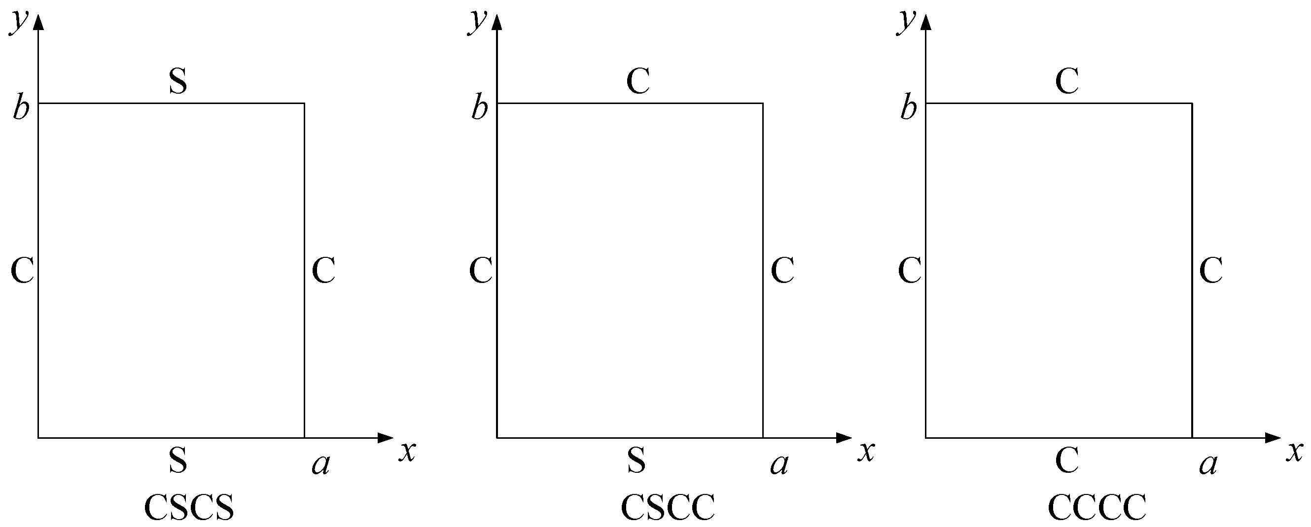
Two types of FGM thin plates are considered in this section. Type-I FGM plate is temperature-dependent; it is made from stainless steel (SUS304) and Silicon nitride (Si3N4). The material properties are shown in Table 4. Type-II FGM plate is temperature-independent; it is made from aluminum as its bottom surface and aluminum oxide as its top surface. Et = 70 GPa, αt = 23 × 10−6/K, Eb = 380 GPa, αb = 7.4 × 10⁻⁶/K, ν = 0.3. Plates with different boundary conditions investigated below are shown in Figure 2.
Firstly, the results of the present method are compared with those in the literature to validate the correctness of this method. Table 5 and Table 6 compare the critical buckling temperature ΔTcr of simply supported type-II FGM square plate based on different theories. Table 7 compares ΔTcr of fully clamped type-II FGM rectangular plate. It can be seen that the present results coincide well with available results.
Table 8 and Table 9 show ΔTcr of type-I FGM thin plate under a uniform temperature field with different boundary conditions. The results indicate that fully clamped (CCCC) plates have the largest ΔTcr, and ΔTcr decreases as the power law index n increases. Table 10 and Table 11 give ΔTcr of Type-I FGM thin plate under different temperature fields. Due to the small difference between the temperature distribution of the linear temperature field and nonlinear temperature field, ΔTcr under these two temperature fields is close. Furthermore, ΔTcr under a uniform temperature field is obviously lower than that under the other two temperature fields, so a uniform temperature field affects ΔTcr more significantly than the other two. Table 12 presents ΔTcr of Type-I FGM thin plate with different initial temperatures T0.
In addition, the critical temperatures are also plotted in Figure 3, Figure 4, Figure 5 and Figure 6 for different thickness–length ratios h/a, power law indexes n, length–width ratios a/b and initial temperatures T0 for type-I FGM plate. Figure 3 shows the relation between ΔTcr and h/a for type-I FGM plate. The critical buckling temperature ΔTcr increases as h/a increases since the thicker plates have larger bending rigidities than the thinner ones. One can also see that the critical buckling temperature of rectangular CCCC plate is the highest, whereas that of the CSCS plate is the lowest; this is because the CCCC plate has the highest bending rigidity compared with the other two cases. Furthermore, the uniform temperature field influences ΔTcr more remarkably than the other two temperature fields.
Figure 4 demonstrates that ΔTcr decreases as n decreases. It can be concluded from Equation (16) that the volume fraction of metal increases as n increases, and metallic materials have a lower critical buckling temperature than ceramic materials; this is because the thermal expansion coefficient α of ceramic materials is less than that of metallic materials.
Figure 5 shows the relation between ΔTcr and a/b for different n. It is observed that, with a/b increasing, ΔTcr increases gradually whatever n is; this indicates that the longer plates have a higher critical buckling temperature for different n. Homogeneous isotropic ceramic plate has the highest ΔTcr and metallic plate has the lowest, and the volume fraction of the metal component increases as n increases.
Figure 6 indicates that ΔTcr of type-I FGM plate decreases almost linearly as T0 increases. For temperature-independent material, the ΔTcr stays at a constant value, thus Tcr has the same increment as that of T0. However, for type-I FGM plate, which is made from temperature-dependent materials, ΔTcr decreases almost linearly as T0 increases, and Tcr increases almost linearly, but the increment of Tcr is less than that of T0.
5. Conclusions
In this study, the closed form analytical solutions were obtained via the separation-of-variable method to determine the thermal buckling of FGM thin plates with simply supported, clamped and guided edges. A novel method to find the critical buckling temperature was given; the explicit expressions of the critical buckling temperature were presented for three special cases.
Two types of FGM thin plates and uniform, linear and nonlinear temperature fields were taken into account in this work. The present results coincide well with those in the literature, which illustrates the correctness of this present method. It follows that the critical buckling temperature of FGM thin plates decreases as the length–thickness ratio and power law index increase, and increases as the length–width ratio increases, and the initial temperature affects the critical buckling temperature of temperature-dependent materials. The uniform temperature field has the greatest influence on the critical buckling temperature, and the critical buckling temperatures become very close for both linear and nonlinear temperature fields.
Acknowledgments
The work is supported by the National Natural Science Foundation of China (11372021, 11672019).
Author Contributions
Y.X. conceived the research ideas; Z.W. derived equations, calculated and analyzed numerical results; both authors participated in the writing of this article.
Conflicts of Interest
The authors declare no conflict of interest.
Appendix A

Table A1.
Coefficients of Equation (41).
| A9 | |
| A8 | |
| A7 | |
| A6 | |
| A5 | |
| A4 | |
| A3 | |
| A2 | |
| A1 | |
| A0 |
where
References
- Koizumi, M. The concept of FGM. Funct. Gradient Mater. 1993, 34, 3–10. [Google Scholar] [CrossRef]
- Koizumi, M. FGM activities in Japan. Compos. Part B Eng. 1997, 28, 1–4. [Google Scholar] [CrossRef]
- Javaheri, R.; Eslami, M.R. Thermal buckling of functionally graded plates. AIAA J. 2002, 40, 162–184. [Google Scholar] [CrossRef]
- Shariat, B.S.; Eslami, M.R. Thermal buckling of imperfect functionally graded plates. Int. J. Solids Struct. 2006, 43, 4082–4096. [Google Scholar] [CrossRef]
- Kiani, Y.; Bagherizadeh, E.; Eslami, M.R. Thermal buckling of clamped thin rectangular FGM plates resting on Pasternak elastic foundation (three approximate analytical solutions). J. Appl. Math. Mech. 2011, 91, 581–593. [Google Scholar] [CrossRef]
- Chu, F.; He, J.; Wang, L.; Zhong, Z. Buckling analysis of functionally graded thin plate with in-plane material inhomogeneity. Eng. Anal. Bound. Elem. 2016, 65, 112–125. [Google Scholar] [CrossRef]
- Wu, L. Thermal buckling of a simply supported moderately thick rectangular FGM plate. Compos. Struct. 2004, 64, 211–218. [Google Scholar] [CrossRef]
- Bouazza, M.; Tounsi, A.; Adda-Bedia, E.A.; Megueni, A. Thermoelastic stability analysis of functionally graded plates: An analytical approach. Comput. Mater. Sci. 2010, 49, 865–870. [Google Scholar] [CrossRef]
- Shariat, B.S.; Eslami, M.R. Effect of initial imperfections on thermal buckling of functionally graded plates. J. Therm. Stress. 2005, 28, 1183–1198. [Google Scholar] [CrossRef]
- Lee, Y.H.; Bae, S.I.; Kim, J.H. Thermal buckling behavior of functionally graded plates based on neutral surface. Compos. Struct. 2016, 137, 208–214. [Google Scholar] [CrossRef]
- Park, J.S.; Kim, J.H. Thermal postbuckling and vibration analyses of functionally graded plates. J. Sound Vib. 2006, 289, 77–93. [Google Scholar] [CrossRef]
- Cong, P.H.; Duc, N.D. Thermal stability analysis of eccentrically stiffened sigmoid-FGM plate with metal–ceramic–metal layers based on FSDT. Cogent Eng. 2016, 3. [Google Scholar] [CrossRef]
- Javaheri, R.; Eslami, M.R. Thermal buckling of functionally graded plates based on higher order theory. J. Therm. Stress. 2002, 25, 603–625. [Google Scholar] [CrossRef]
- Najafizadeh, M.M.; Heydari, H.R. Thermal buckling of functionally graded circular plates based on higher order shear deformation plate theory. Eur. J. Mech. A/Solids 2004, 23, 1085–1100. [Google Scholar] [CrossRef]
- Matsunaga, H. Thermal buckling of functionally graded plates according to a 2D higher-order deformation theory. Compos. Struct. 2009, 90, 76–86. [Google Scholar] [CrossRef]
- Zenkour, A.M.; Mashat, D.S. Thermal buckling analysis of ceramic-metal functionally graded plates. Nat. Sci. 2010, 2, 968–978. [Google Scholar] [CrossRef]
- Na, K.S.; Kim, J.H. Three-dimensional thermal buckling analysis of functionally graded materials. Compos. Part B Eng. 2004, 35, 429–437. [Google Scholar] [CrossRef]
- Na, K.S.; Kim, J.H. Three-dimensional thermomechanical buckling analysis for functionally graded composite plates. Compos. Struct. 2006, 73, 413–422. [Google Scholar] [CrossRef]
- Malekzadeh, P. Three-dimensional thermal buckling analysis of functionally graded arbitrary straight-sided quadrilateral plates using differential quadrature method. Compos. Struct. 2011, 93, 1246–1254. [Google Scholar] [CrossRef]
- Asemi, K.; Shariyat, M.; Salehi, M.; Ashrafi, H. A full compatible three-dimensional elasticity element for buckling analysis of FGM rectangular plates subjected to various combinations of biaxial normal and shear loads. Finite Elem. Anal. Des. 2013, 74, 9–21. [Google Scholar] [CrossRef]
- Swaminathan, K.; Sangeetha, D.M. Thermal analysis of FGM plates—A critical review of various modeling techniques and solution methods. Compos. Struct. 2017, 160, 43–60. [Google Scholar] [CrossRef]
- Xu, T.F.; Xing, Y.F. Closed-form solutions for free vibration of rectangular FGM thin plates resting on elastic foundation. Acta Mech. Sin. 2016, 32, 1088–1103. [Google Scholar] [CrossRef]
- Bouhadra, A.; Benyoucef, S.; Tounsi, A.; Bernard, F.; Bouiadjra, R.B.; Sid Ahmed Houari, M. Thermal buckling response of functionally graded plates with clamped boundary conditions. J. Therm. Stress. 2015, 38, 630–650. [Google Scholar] [CrossRef]
- Thornton, E.A. Thermal buckling of plates and shells. Appl. Mech. Rev. 1993, 46, 485–506. [Google Scholar] [CrossRef]
- Xing, Y.F.; Liu, B. New exact solutions for free vibrations of rectangular thin plates by symplectic dual method. Acta Mech. Sin. 2009, 25, 265–270. [Google Scholar] [CrossRef]
- Xing, Y.F.; Liu, B. New exact solutions for free vibrations of thin orthotropic rectangular plates. Compos. Struct. 2009, 104, 187–195. [Google Scholar] [CrossRef]
- Xing, Y.F.; Xu, T.F. Solution methods of exact solutions for free vibration of rectangular orthotropic thin plates with classical boundary conditions. Compos. Struct. 2013, 104, 187–195. [Google Scholar] [CrossRef]
Figure 1.
Functionally Graded Material (FGM) thin plate and Cartesian coordinates.

Figure 2.
Plates with different boundary conditions.

Figure 3.
The relation between the critical buckling temperature ΔTcr and the length–thickness ratio h/a of type-I FGM rectangular thin plate (a/b = 2, n = 2, T0 = 300 K).
Figure 3.
The relation between the critical buckling temperature ΔTcr and the length–thickness ratio h/a of type-I FGM rectangular thin plate (a/b = 2, n = 2, T0 = 300 K).
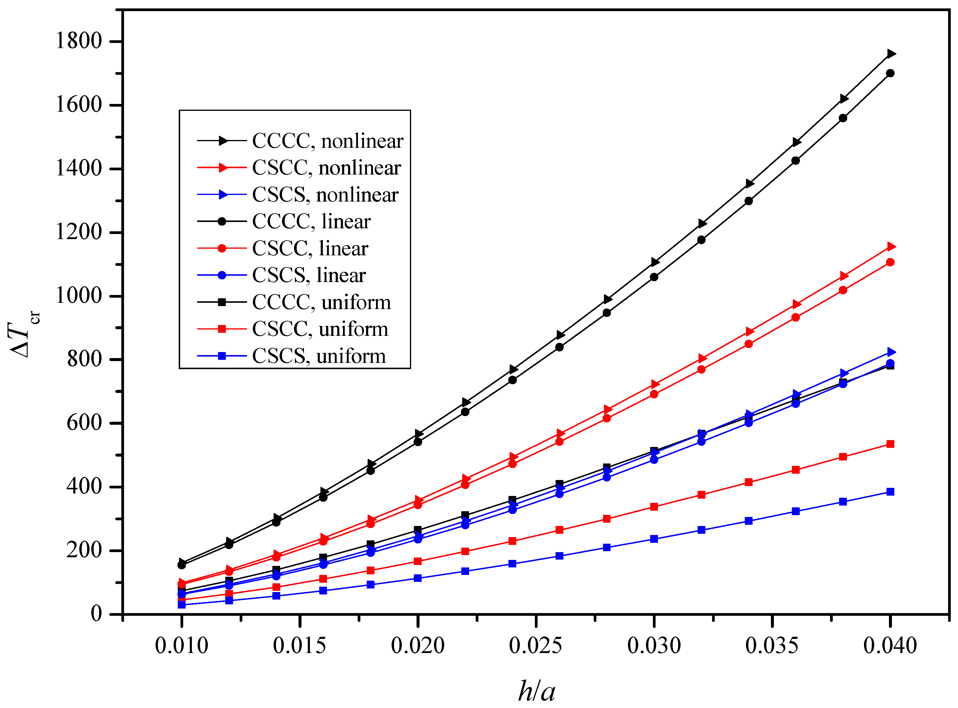
Figure 4.
The relation between the critical buckling temperature ΔTcr and power law index n of type-I FGM rectangular thin plate (a/h = 100, a/b = 2, T0 = 300 K).
Figure 4.
The relation between the critical buckling temperature ΔTcr and power law index n of type-I FGM rectangular thin plate (a/h = 100, a/b = 2, T0 = 300 K).
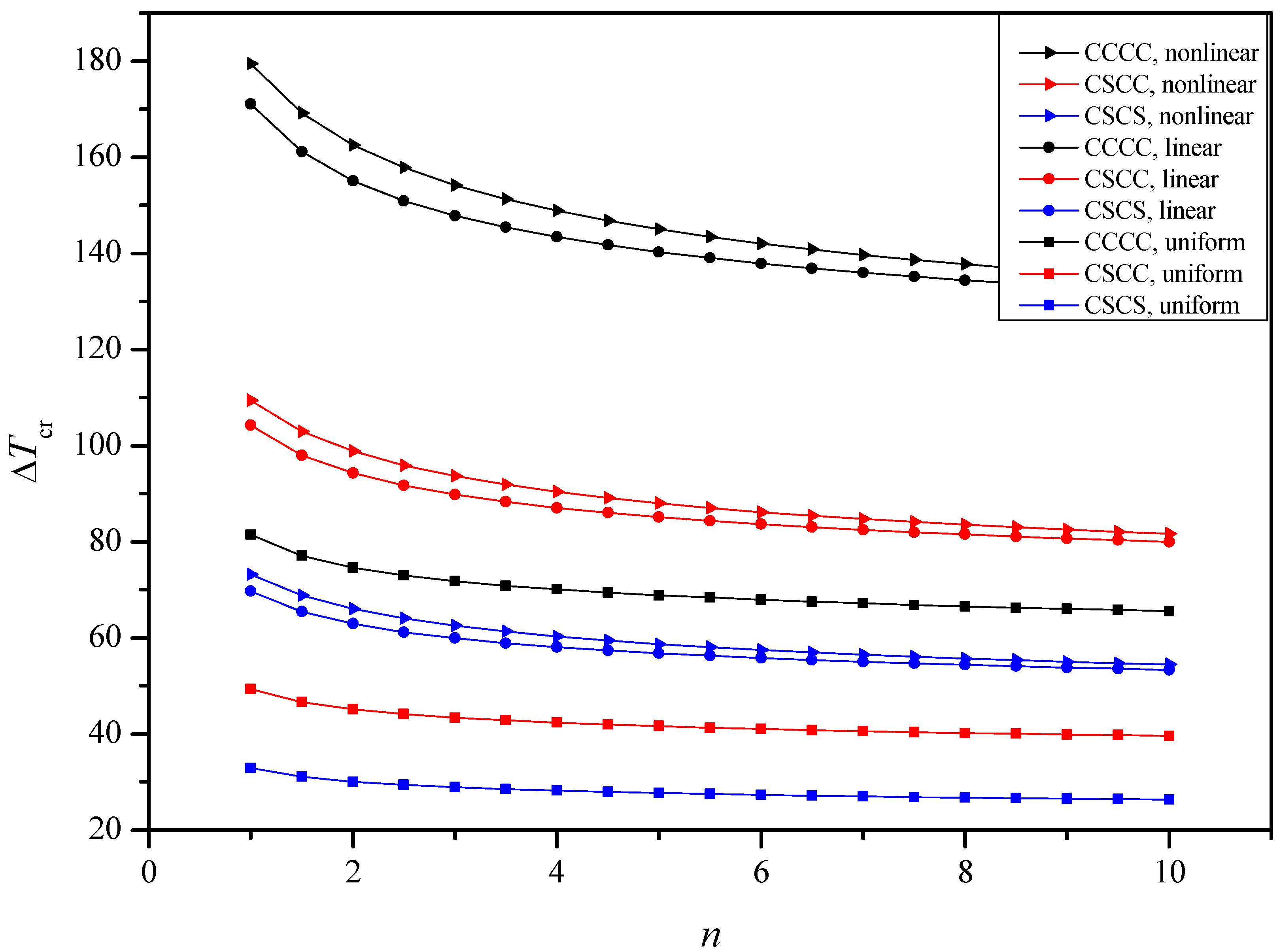
Figure 5.
The relation between the critical buckling temperature ΔTcr and the length–width ratio a/b of type-I FGM, ceramic and metal rectangular thin plate (a/h = 100, n = 2, T0 = 300 K).
Figure 5.
The relation between the critical buckling temperature ΔTcr and the length–width ratio a/b of type-I FGM, ceramic and metal rectangular thin plate (a/h = 100, n = 2, T0 = 300 K).
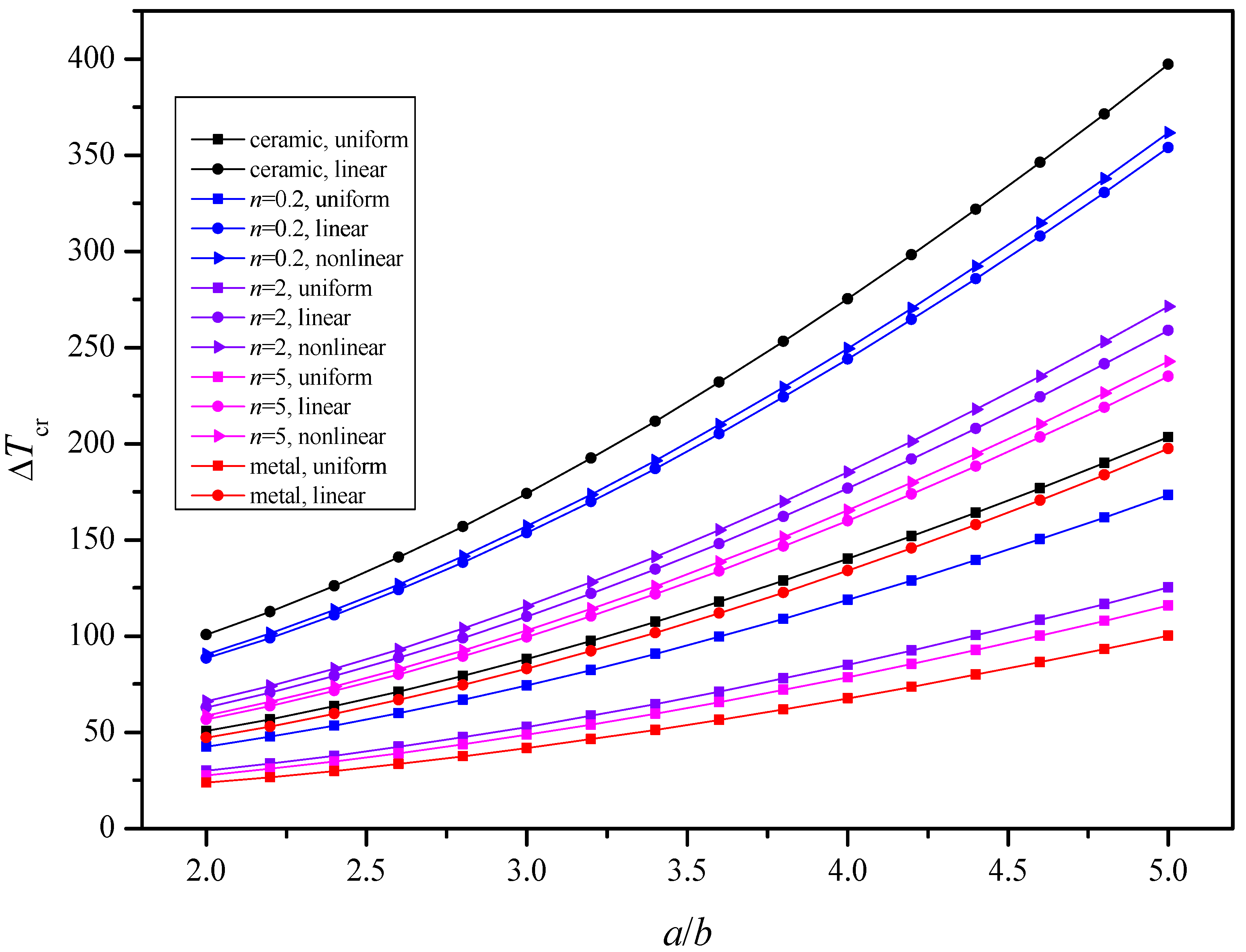
Figure 6.
(a) The relation between ΔTcr and the initial temperature T0 of type-I FGM rectangular thin plate (a/h = 100, a/b = 2, n = 2); (b) The relation between Tcr and the initial temperature T0 of type-I FGM rectangular thin plate (a/h = 100, a/b = 2, n = 2).
Figure 6.
(a) The relation between ΔTcr and the initial temperature T0 of type-I FGM rectangular thin plate (a/h = 100, a/b = 2, n = 2); (b) The relation between Tcr and the initial temperature T0 of type-I FGM rectangular thin plate (a/h = 100, a/b = 2, n = 2).
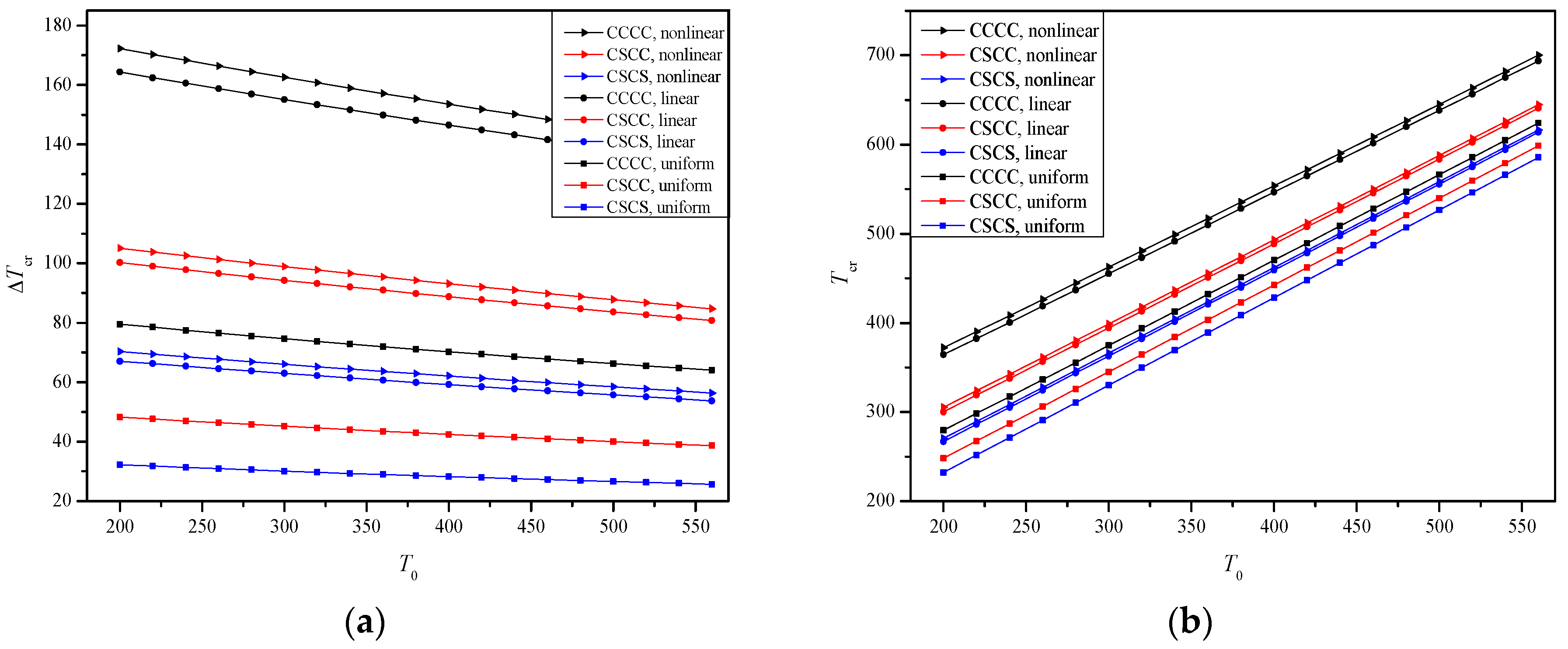
Table 1.
Boundary conditions of a rectangular plate.
| Simple Support (S) | ||
| Guide (G) | ||
| Clamp (C) |
Table 2.
Eigenvalue equations for various boundary conditions.
| B.C. | Eigenvalue Equations for y = 0 and b | Eigenvalue Equations for x = 0 and a |
|---|---|---|
| S-S | ||
| G-G | ||
| C-C | ||
| S-G | ||
| S-C | ||
| G-C |
Table 3.
The integrals in Equation (38).
| Integral | Uniform Temperature Field | Linear Temperature Field | Nonlinear Temperature Field |
|---|---|---|---|
| J0 | |||
| J1 | |||
| J2 | |||
| J3 | |||
| J4 | |||
| J5 |
Table 4.
The material properties of type-I FGM plate.
| Property | Material Type | P−1 | P0 | P1 | P2 | P3 |
|---|---|---|---|---|---|---|
| E | Si3N4 | 0 | 348.43 × 10⁹ | −3.070 × 10⁻⁴ | 2.160 × 10⁻⁷ | −8.946 × 10⁻¹¹ |
| SUS304 | 0 | 201.04 × 10⁹ | 3.079 × 10⁻⁴ | −6.534 × 10⁻⁷ | 0 | |
| ν | Si3N4 | 0 | 0.2400 | 0 | 0 | 0 |
| SUS304 | 0 | 0.3262 | −2.002 × 10⁻⁴ | 3.797 × 10⁻⁷ | 0 | |
| α | Si3N4 | 0 | 5.8723 × 10⁻⁶ | 9.095 × 10⁻⁴ | 0 | 0 |
| SUS304 | 0 | 12.330 × 10⁻⁶ | 8.086 × 10⁻⁴ | 0 | 0 | |
| ρ | Si3N4 | 0 | 2370 | 0 | 0 | 0 |
| SUS304 | 0 | 8166 | 0 | 0 | 0 | |
| k | Si3N4 | 0 | 9.19 | 0 | 0 | 0 |
| SUS304 | 0 | 12.04 | 0 | 0 | 0 |
Table 5.
Critical buckling temperature ΔTcr of SSSS type-II FGM square plate with different a/h under a uniform temperature field (a/b = 1).
Table 5.
Critical buckling temperature ΔTcr of SSSS type-II FGM square plate with different a/h under a uniform temperature field (a/b = 1).
| n | Method | a/h = 10 | a/h = 20 | a/h = 40 | a/h = 60 | a/h = 80 | a/h = 100 |
|---|---|---|---|---|---|---|---|
| 1 | Present | 782.016 | 197.813 | 49.600 | 22.056 | 12.409 | 7.943 |
| CPT [15] | 794.377 | 198.594 | 49.648 | 22.066 | 12.412 | 7.943 | |
| TSDT [15] | 757.891 | 196.257 | 49.500 | 22.037 | 12.402 | 7.939 | |
| HDT5 [15] | 749.260 | 195.623 | 49.404 | 22.029 | 12.400 | 7.939 | |
| 5 | Present | 713.894 | 180.841 | 45.361 | 20.173 | 11.350 | 7.265 |
| CPT [15] | 726.571 | 181.642 | 45.410 | 20.182 | 11.352 | 7.265 | |
| TSDT [15] | 678.926 | 178.528 | 45.213 | 20.144 | 11.340 | 7.260 | |
| HDT5 [15] | 669.402 | 177.805 | 45.166 | 20.134 | 11.337 | 7.259 | |
| 10 | Present | 733.217 | 185.863 | 46.629 | 20.737 | 11.667 | 7.468 |
| CPT [15] | 746.927 | 186.731 | 46.682 | 20.747 | 11.670 | 7.469 | |
| TSDT [15] | 692.519 | 183.141 | 46.455 | 20.703 | 11.657 | 7.462 | |
| HDT5 [15] | 683.211 | 182.432 | 46.409 | 20.694 | 11.654 | 7.462 |
Table 6.
Critical buckling temperature ΔTcr of SSSS type-II FGM plate with different a/b under a uniform temperature field (a/h = 100).
Table 6.
Critical buckling temperature ΔTcr of SSSS type-II FGM plate with different a/b under a uniform temperature field (a/h = 100).
| n | Method | a/b = 1 | a/b = 2 | a/b = 3 | a/b = 4 | a/b = 5 |
|---|---|---|---|---|---|---|
| 1 | Present | 7.9426 | 19.8516 | 39.6876 | 67.4319 | 103.0568 |
| CPT [16] | 7.9437 | 19.8594 | 39.7188 | 67.5220 | 103.2690 | |
| FPT [16] | 7.9400 | 19.8358 | 39.6248 | 67.2506 | 102.6355 | |
| TSDT [16] | 7.9400 | 19.8358 | 39.6248 | 67.2506 | 102.6356 | |
| SSDT [16] | 7.9400 | 19.8359 | 39.6249 | 67.2510 | 102.6365 | |
| 2 | Present | 7.0415 | 17.5995 | 35.1851 | 59.7816 | 91.3644 |
| CPT [16] | 7.0426 | 17.6065 | 35.2130 | 59.8621 | 91.5538 | |
| FPT [16] | 7.0392 | 17.5853 | 35.1285 | 59.6184 | 91.9850 | |
| TSDT [16] | 7.0390 | 17.5840 | 35.1234 | 59.6037 | 90.9508 | |
| SSDT [16] | 7.0390 | 17.5840 | 35.1233 | 59.6034 | 90.9501 | |
| 5 | Present | 7.2645 | 18.1563 | 36.2964 | 61.6659 | 94.2363 |
| CPT [16] | 7.2657 | 18.1642 | 36.3285 | 61.7585 | 94.4542 | |
| FPT [16] | 7.2615 | 18.1380 | 36.2236 | 61.4559 | 93.7481 | |
| TSDT [16] | 7.2606 | 18.1327 | 36.2025 | 61.3951 | 93.6069 | |
| SSDT [16] | 7.2606 | 18.1324 | 36.2014 | 61.3921 | 93.5999 | |
| 10 | Present | 7.4679 | 18.6645 | 37.3115 | 63.3884 | 96.8646 |
| CPT [16] | 7.4692 | 18.6731 | 37.3463 | 63.4888 | 97.1005 | |
| FPT [16] | 7.4644 | 18.6427 | 37.2246 | 63.1378 | 96.2820 | |
| TSDT [16] | 7.4634 | 18.6366 | 37.2006 | 63.0687 | 96.1213 | |
| SSDT [16] | 7.4634 | 18.6365 | 37.2001 | 63.0673 | 96.1183 |
Table 7.
Critical buckling temperature ΔTcr of CCCC type-II FGM rectangular plate under a uniform temperature field (a/h = 100, a/b = 2).
Table 7.
Critical buckling temperature ΔTcr of CCCC type-II FGM rectangular plate under a uniform temperature field (a/h = 100, a/b = 2).
| Method | n = 0 | n = 0.5 | n = 1 | n = 2 | n = 5 | n = 10 |
|---|---|---|---|---|---|---|
| Present | 32.355 | 18.332 | 15.032 | 13.326 | 13.748 | 14.133 |
| Kiani [5] | 33.628 | 19.053 | 15.623 | 13.850 | 14.289 | 14.690 |
Table 8.
Critical buckling temperature ΔTcr of type-I FGM rectangular thin plate with different a/h and various B.C. under a uniform temperature field (a/b = 2, T0 = 300 K).
Table 8.
Critical buckling temperature ΔTcr of type-I FGM rectangular thin plate with different a/h and various B.C. under a uniform temperature field (a/b = 2, T0 = 300 K).
| B.C. | n | a/h = 20 | a/h = 30 | a/h = 40 | a/h = 50 | a/h = 60 | a/h = 70 | a/h = 80 |
|---|---|---|---|---|---|---|---|---|
| CSCS | 1 | 583.7802 | 306.6174 | 186.0370 | 123.9484 | 88.1339 | 65.7278 | 50.8301 |
| 2 | 547.3748 | 283.8704 | 171.2913 | 113.7826 | 80.7593 | 60.1576 | 46.4854 | |
| 5 | 517.0574 | 264.5071 | 158.8189 | 105.2290 | 74.5765 | 55.4993 | 42.8584 | |
| CSCC | 1 | 783.2272 | 431.1364 | 267.9431 | 181.1536 | 130.0341 | 97.5959 | 75.8125 |
| 2 | 742.2713 | 401.3746 | 247.6355 | 166.7565 | 119.4051 | 89.4729 | 69.4245 | |
| 5 | 713.3132 | 376.0498 | 230.3741 | 154.5835 | 110.4567 | 82.6559 | 64.0761 | |
| CCCC | 1 | 1057.5407 | 640.8390 | 413.1423 | 285.7974 | 208.3541 | 158.0883 | 123.7707 |
| 2 | 1013.9656 | 602.6029 | 384.3119 | 264.3487 | 192.0395 | 145.3645 | 113.6185 | |
| 5 | 1030.1122 | 571.4283 | 359.7632 | 246.1036 | 178.2185 | 134.6260 | 105.0764 |
Note: ‘B.C.’ stands for Boundary Condition.
Table 9.
Critical buckling temperature ΔTcr of type-I FGM rectangular thin plate with different a/b and various B.C. under a uniform temperature field (a/h = 100, T0 = 300 K).
Table 9.
Critical buckling temperature ΔTcr of type-I FGM rectangular thin plate with different a/b and various B.C. under a uniform temperature field (a/h = 100, T0 = 300 K).
| B.C. | n | a/b = 2 | a/b = 3 | a/b = 4 | a/b = 5 | a/b = 6 | a/b = 7 |
|---|---|---|---|---|---|---|---|
| CSCS | 1 | 32.9286 | 57.7537 | 92.8929 | 136.4766 | 187.0319 | 243.2765 |
| 2 | 30.0846 | 52.8369 | 85.1409 | 125.3608 | 172.2154 | 224.5874 | |
| 5 | 27.7157 | 48.7288 | 78.6384 | 115.9968 | 159.6822 | 208.7213 | |
| CSCC | 1 | 49.3892 | 100.7232 | 168.6840 | 248.9947 | 338.3012 | 433.8633 |
| 2 | 45.1642 | 92.3546 | 155.1861 | 229.9260 | 313.6459 | 403.9628 | |
| 5 | 41.6377 | 85.3292 | 143.7844 | 213.7327 | 292.6429 | 378.5233 | |
| CCCC | 1 | 81.4595 | 176.7382 | 295.2208 | 428.0121 | 568.5417 | 711.2512 |
| 2 | 74.6176 | 162.6580 | 273.1802 | 398.4099 | 532.6899 | 671.3248 | |
| 5 | 68.8856 | 150.7570 | 254.4250 | 373.2176 | 502.7141 | 640.2733 |
Table 10.
Critical buckling temperature ΔTcr of type-I FGM rectangular thin plate with different a/h and various B.C. (a/b = 2, n = 2, T0 = 300 K).
Table 10.
Critical buckling temperature ΔTcr of type-I FGM rectangular thin plate with different a/h and various B.C. (a/b = 2, n = 2, T0 = 300 K).
| B.C. | T.F. | a/h = 20 | a/h = 30 | a/h = 40 | a/h = 50 | a/h = 60 | a/h = 70 |
|---|---|---|---|---|---|---|---|
| CSCS | uniform | 547.3748 | 283.8704 | 171.2913 | 113.7826 | 80.7593 | 60.1576 |
| linear | 1133.6559 | 581.2390 | 352.4874 | 235.3624 | 167.7132 | 125.2884 | |
| nonlinear | 1182.5836 | 607.9852 | 369.1144 | 246.6213 | 175.8071 | 131.3707 | |
| CSCC | uniform | 742.2713 | 401.3746 | 247.6355 | 166.7565 | 119.4051 | 89.4729 |
| linear | 1594.4982 | 822.6864 | 507.5211 | 343.2718 | 246.8452 | 185.6015 | |
| nonlinear | 1655.7434 | 859.5887 | 531.0572 | 359.4812 | 258.6364 | 194.5373 | |
| CCCC | uniform | 1013.9656 | 602.6029 | 384.3119 | 264.3487 | 192.0395 | 145.3645 |
| linear | 2230.3048 | 1256.9658 | 787.2933 | 541.4994 | 394.6294 | 299.7612 | |
| nonlinear | 2275.4643 | 1310.1371 | 822.7439 | 566.5211 | 413.1558 | 313.9882 |
Note: ‘T.F.’ represents Temperature Field.
Table 11.
Critical buckling temperature ΔTcr of type-I FGM rectangular thin plate with different a/b and various B.C. (a/h = 100, n = 2, T0 = 300 K).
Table 11.
Critical buckling temperature ΔTcr of type-I FGM rectangular thin plate with different a/b and various B.C. (a/h = 100, n = 2, T0 = 300 K).
| B.C. | T.F. | a/b = 2 | a/b = 3 | a/b = 4 | a/b = 5 | a/b = 6 | a/b = 7 |
|---|---|---|---|---|---|---|---|
| CSCS | uniform | 30.0846 | 52.8369 | 85.1409 | 125.3608 | 172.2154 | 224.5874 |
| linear | 62.9589 | 110.1631 | 176.7119 | 258.9990 | 354.3651 | 460.7078 | |
| nonlinear | 66.0438 | 115.5227 | 185.2298 | 271.3522 | 371.0771 | 482.1803 | |
| CSCC | uniform | 45.1642 | 92.3546 | 155.1861 | 229.9260 | 313.6459 | 403.9628 |
| linear | 94.2791 | 191.5108 | 319.7465 | 471.5480 | 642.0001 | 828.0680 | |
| nonlinear | 98.8767 | 200.7238 | 334.8863 | 493.5001 | 671.3553 | 865.1898 | |
| CCCC | uniform | 74.6176 | 162.6580 | 273.1802 | 398.4099 | 532.6899 | 671.3248 |
| linear | 155.0859 | 334.9406 | 559.4693 | 816.5263 | 1101.5178 | 1417.3660 | |
| nonlinear | 162.5833 | 350.7718 | 585.2726 | 853.1769 | 1149.2782 | 1475.2611 |
Table 12.
Critical buckling temperature ΔTcr of type-I FGM rectangular thin plate with different initial temperature T0 (a/h = 100, a/b = 2, n = 2).
Table 12.
Critical buckling temperature ΔTcr of type-I FGM rectangular thin plate with different initial temperature T0 (a/h = 100, a/b = 2, n = 2).
| B.C. | T.F. | T0 = 300 | T0 = 350 | T0 = 400 | T0 = 450 | T0 = 500 | T0 = 550 |
|---|---|---|---|---|---|---|---|
| CSCS | uniform | 30.0846 | 29.1293 | 28.2271 | 27.3736 | 26.5646 | 25.7966 |
| linear | 62.9589 | 61.0372 | 59.1907 | 57.4131 | 55.6986 | 54.0411 | |
| nonlinear | 66.0438 | 64.0307 | 62.0950 | 60.2304 | 58.4306 | 56.6896 | |
| CSCC | uniform | 45.1642 | 43.7545 | 42.4210 | 41.1575 | 39.9584 | 38.8184 |
| linear | 94.2791 | 91.4769 | 88.7779 | 86.1741 | 83.6574 | 81.2201 | |
| nonlinear | 98.8767 | 95.9427 | 93.1148 | 90.3846 | 87.7440 | 85.1846 | |
| CCCC | uniform | 74.6176 | 72.3631 | 70.2244 | 68.1925 | 66.259 | 64.4162 |
| linear | 155.0859 | 150.7014 | 146.4609 | 142.3542 | 138.3707 | 134.4997 | |
| nonlinear | 162.5833 | 157.9968 | 153.5573 | 149.2545 | 145.0775 | 141.0154 |
© 2017 by the authors. Licensee MDPI, Basel, Switzerland. This article is an open access article distributed under the terms and conditions of the Creative Commons Attribution (CC BY) license (http://creativecommons.org/licenses/by/4.0/).
Share and Cite
MDPI and ACS Style
Xing, Y.; Wang, Z. Closed Form Solutions for Thermal Buckling of Functionally Graded Rectangular Thin Plates. Appl. Sci. 2017, 7, 1256. https://doi.org/10.3390/app7121256
AMA Style
Xing Y, Wang Z. Closed Form Solutions for Thermal Buckling of Functionally Graded Rectangular Thin Plates. Applied Sciences. 2017; 7(12):1256. https://doi.org/10.3390/app7121256
Chicago/Turabian StyleXing, Yufeng, and Zekun Wang. 2017. "Closed Form Solutions for Thermal Buckling of Functionally Graded Rectangular Thin Plates" Applied Sciences 7, no. 12: 1256. https://doi.org/10.3390/app7121256
Note that from the first issue of 2016, this journal uses article numbers instead of page numbers. See further details here.