Off-Line Optimization Based Active Control of Torsional Oscillation for Electric Vehicle Drivetrain

1
National Engineering Laboratory for Electric Vehicles, Beijing Institute of Technology, Beijing 100081, China
2
Collaborative Innovation Center of Electric Vehicles in Beijing, Beijing 100081, China
3
Faculty of engineering and IT, University of Technology Sydney, 15 Broadway, Ultimo, NSW 2007, Australia
*
Author to whom correspondence should be addressed.
Appl. Sci. 2017, 7(12), 1261; https://doi.org/10.3390/app7121261
Submission received: 26 September 2017
/
Revised: 25 November 2017
/
Accepted: 29 November 2017
/
Published: 4 December 2017
(This article belongs to the Section Mechanical Engineering)
Abstract
:As there is no clutch or hydraulic torque converter in electric vehicles to buffer and absorb torsional vibrations. Oscillation will occur in electric vehicle drivetrains when drivers tip in/out or are shifting. In order to improve vehicle response to transients, reduce vehicle jerk and reduce wear of drivetrain parts, torque step changes should be avoided. This article mainly focuses on drivetrain oscillations caused by torque interruption for shifting in a Motor-Transmission Integrated System. It takes advantage of the motor responsiveness, an optimal active control method is presented to reduce oscillations by adjusting motor torque output dynamically. A rear-wheel-drive electric vehicle with a two gear automated manual transmission is considered to set up dynamic differential equations based on Newton’s law of motion. By linearization of the affine system, a joint genetic algorithm and linear quadratic regulator method is applied to calculate the real optimal motor torque. In order to improve immediacy of the control system, time consuming optimization process of parameters is completed off-line. The active control system is tested in AMEsim® and limitation of motor external characteristics are considered. The results demonstrate that, compared with the open-loop system, the proposed algorithm can reduce motion oscillation to a satisfied extent when unloading torque for shifting.
1. Introduction
With the increasing emergence of environment and energy issues as factors impacting on the design of passenger transportation system, scholars all over the world are devoting themselves to finding alternative energy and clean energy solutions for industry [1]. As a major energy-consuming product, reducing fuel consumption or finding alternative energy resources are significant targets for the automotive industry [2], electric vehicles (EV) have advantages of lower transportation cost, no direct emissions, no consumption of fuel, and smoother driving experience, which has drawn attention from vehicle designers and academics around the world. In 1976, a law is passed in America to ensure the healthy development of the electric vehicle industry [3]; today, the electric vehicle is occupying a larger and larger market share.
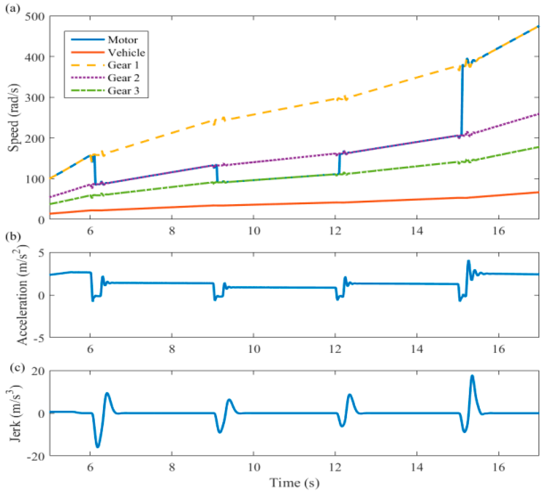
There are many differences in the drivetrain for traditional fuel-consuming vehicles and electric vehicles. The main parts of a typical a rear-wheel drive electric vehicle drivetrain are motor, transmission, shafts, and wheels as shown in Figure 1. A typical compact automobile drivetrain integrates the motor and automated manual transmission (AMT) with final drive to reduce speed and generate larger torque for driving the vehicle. The most obvious difference is that there is no clutch or hydraulic torque converter in electric vehicles. Considering the elastic and damping parts, the drivetrain should be regarded as a second order oscillatory system, because there are fewer parts to interrupt the transmission of power, and no parts to buffer or absorb torsional vibration oscillation caused by rapid torque changes. Figure 2, cited from reference [4], shows the typical oscillations of driveline when shifting.
The primary dynamic response in vehicle drivetrain is referred to as shuffle, and is linked to the lowest natural frequency of the drivetrain. This is one of the most critical issues of motor-transmission directly coupled to the drive system of electric vehicles. Some of these oscillations are transmitted through the bearing mounts and transmission shafts to the gearbox housing. In some instances it may be radiated into the environment as noise as well [5]. Improving the performance of the driveline by reducing undesirable oscillations is, therefore, a critical issue in automotive development.
There are two main kinds of schemes to solve such problems, one is to add torsional shock absorbers or clutch [6]. In 2009 Zhang et al. [7] have analyzed electric vehicle drivelines and drawn a conclusion that it is an underdamped vibration system. Oscillations can be reduced by designing a damper, but it may introduce other vibrations caused by structural change, and it also increases complexity of the system and manufacturing cost. The other option is controlling the motor reference torque output, by adjusting motor torque output dynamically to give the driveline torque compensation against oscillation; this is an active control method.
Templin et al. [8] at Sweden Linköping University has conducted research on shifting without detaching the clutch for a heavy truck with an internal combustion engine, by applying engine torque control during gear shifting to unload torque, minimize shift time and increase shift quality. Subsequent research has shown that there are still many researchers investigating active control for drivetrain vibrations by controlling engine torque output actively and dynamically with feed forward control method [9], optimal algorithm [10,11], model predictive control [12,13], H-infinity optimization [14] to replace the simple open-loop system to reduce oscillation when shifting or during tip in/out. The core principles of the above concepts are similar, by controlling engine torque according to drivetrain motion state, a controller will compensate for the speed oscillations. Such a compensator will act as a feedback unit so that a close-loop system is composed to improve drivetrain system performance. However, because the inherent defects of engines (such as variability of output torque) have limited success in terms of accuracy of control and rapid response, it is difficult to apply the above methods to control engine torque to compensate motion oscillation of drivetrain in a certain frequency band.
The ongoing development of electric motors and associated power electronics produces a system that can be easily and precisely controlled. Mohsen et al. have proposed two approaches for the implementation of finite-control-set model predictive control (FCS-MPC) methods to control a permanent-magnet synchronous motor torque fed by a matrix converter; these methods were presented and their results were evaluated experimentally. Neither method needs a current PI controller and modulator, which leads to a fast dynamic [15]. Yulin et al. have improved MPC by proposing an alternative strategy of finite-control-set model-predictive torque control (MPTC), so that the computational burden and the torque ripple can decouple the switching frequency from the controller sampling time, which is then reduced [16]. Furthermore, motors installed in electric vehicles have shown an excellent performance with higher efficiency, lower response times, higher power density [17]; some scholars investigated the problem of automatic speed tracking control of an electric vehicle based on higher order sliding mode (HOSM) observer for the events of sensor faults/failures to maintain a good control performance [18]. More adaptable than conventional engines, electric motors can overcome large resisting moment of inertia during vehicle launch, with the motor connected rigidly and directly to the wheels. As the motor does not stall, the clutch and torque converter are no longer required. The structure of the electric vehicle drivetrain is consequently much simpler and more compact.
Based on the advantages of electric motors, many researchers are determined to realize the active control for EV drivetrain oscillation. In 2015 Song et al. [19] applied fuzzy logic to control motor torque to actively reduce oscillations. Bang et al. [20] presented a novel filter using wheel speeds to eliminate oscillations and improve the robustness of EV control. In 2008 Orlowska-Kowalska et al. [21] proposed an adaptive sliding neuro-fuzzy speed controller for the drive system to improve robustness of control system. Similarly, in 2015 Chen et al. [22] applied mode-switching-based active control of drivetrain for EV during regenerative braking. However, some of these algorithms are too complicate to be applied practically, or too time-consuming to meet the requirements of torsional oscillation frequency up to several dozens of Hertz. Furthermore, the limitations of motor external characteristics are also not considered. Aimed at a kind of motor-transmission integrated drive system, Fu et al. [23] proposed an adaptive method by using the linear quadratic regulator (LQR) and dimensionality reduction observer joint algorithm.
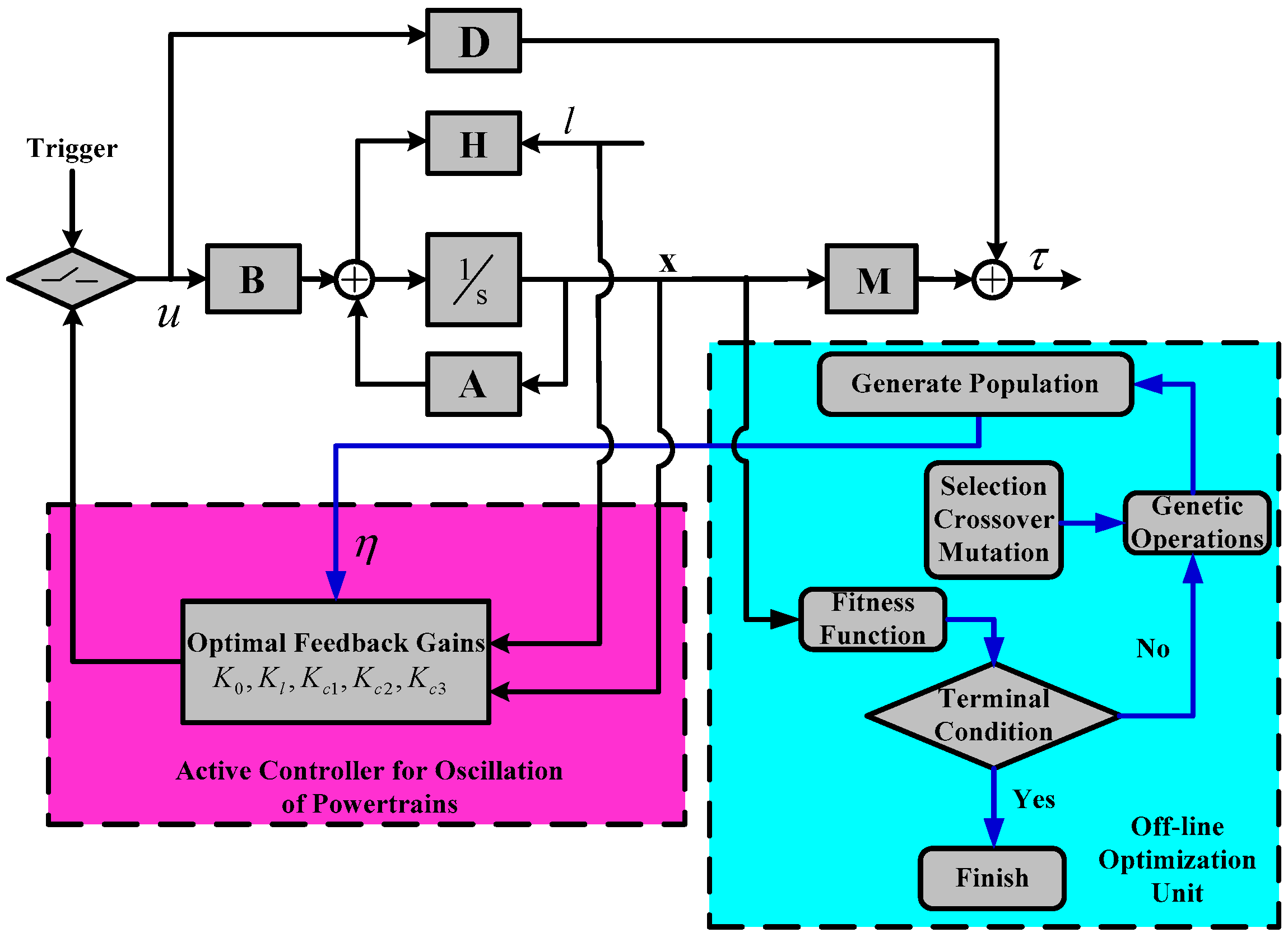
At present, the linear quadratic regulator control algorithm has been found to be one of the most effective methods in vibration control under the premise of appropriate weighting matrices, which gives optimal control gain by minimizing the performance index [24,25,26]. The weighting matrices Q and R will influence the optimal result directly. However, they are selected based on designer’s subjective preference currently and generally; also, such optimal results may not be the real optimal value and even may cause side-effects. Many researchers are looking for methods to choose appropriate weighting matrices to bring a better control performance [27,28,29]. This work aims to present a joint genetic algorithm (GA) and optimal control method for the suppression of oscillations in EV drivetrain. The genetic algorithm searches for the optimum selection of weighting matrices off-line, and this process regards root mean square (RMS) of motor rotational oscillation, drive-shaft rotational oscillation, and drive-shaft twist angle as the multi-objective optimization cost function, so that a reduced jerking feel and improved shift quality can be realized. This active anti-jerking control system is tested on AMEsim® (Version 15, Siemens, Beersel, Belgium, 2016). The results demonstrate that it can realize rapid unloading of the motor output torque to the transmission to zero before opening the synchronizer mechanism for shifting. At the same time, oscillations of EV driveline are actively damped to a satisfactory extent in comparison to open-loop and a reference control strategy.
2. Drivetrain Modelling
The establishment of drivetrain is based on a rear-wheel-drive electric vehicle with integrated motor-transmission system. A six degrees of freedom model is applied to develop the dynamic equation as shown in Figure 3, it can reveal frequency characteristics, decoupling ratio, transmissibility, etc. of the EV drivetrain more accurately than the conventional two or three degrees of the freedom model [30]. The drivetrain model consists of motor rotor, input shaft and output shaft of transmission (neglecting gear lash), final drive, flexible drive shaft, wheels, and translational mass of vehicle body. The symbols and subscripts of the drivetrain mathematical model are shown in Table 1.
Based on the dynamic equations of each part, the EV drivetrain model can be transformed to state space model as shown in Equation (1) and torsional angle, wheel speed and motor rotor speed are selected as the state variables:
where denote
with
In the above equations, u is the motor torque output, , are coefficients in fitting formula of rolling resistance , and from reference [31], they are set as 0.01 and 0.002, respectively. Considering that the process of shifting occurs over a short time period, drag torque l is regarded as a constant. The EV drivetrain is modeled in AMEsim® and these tests are shown in Figure 4.
3. Active Control System
3.1. Controller Design
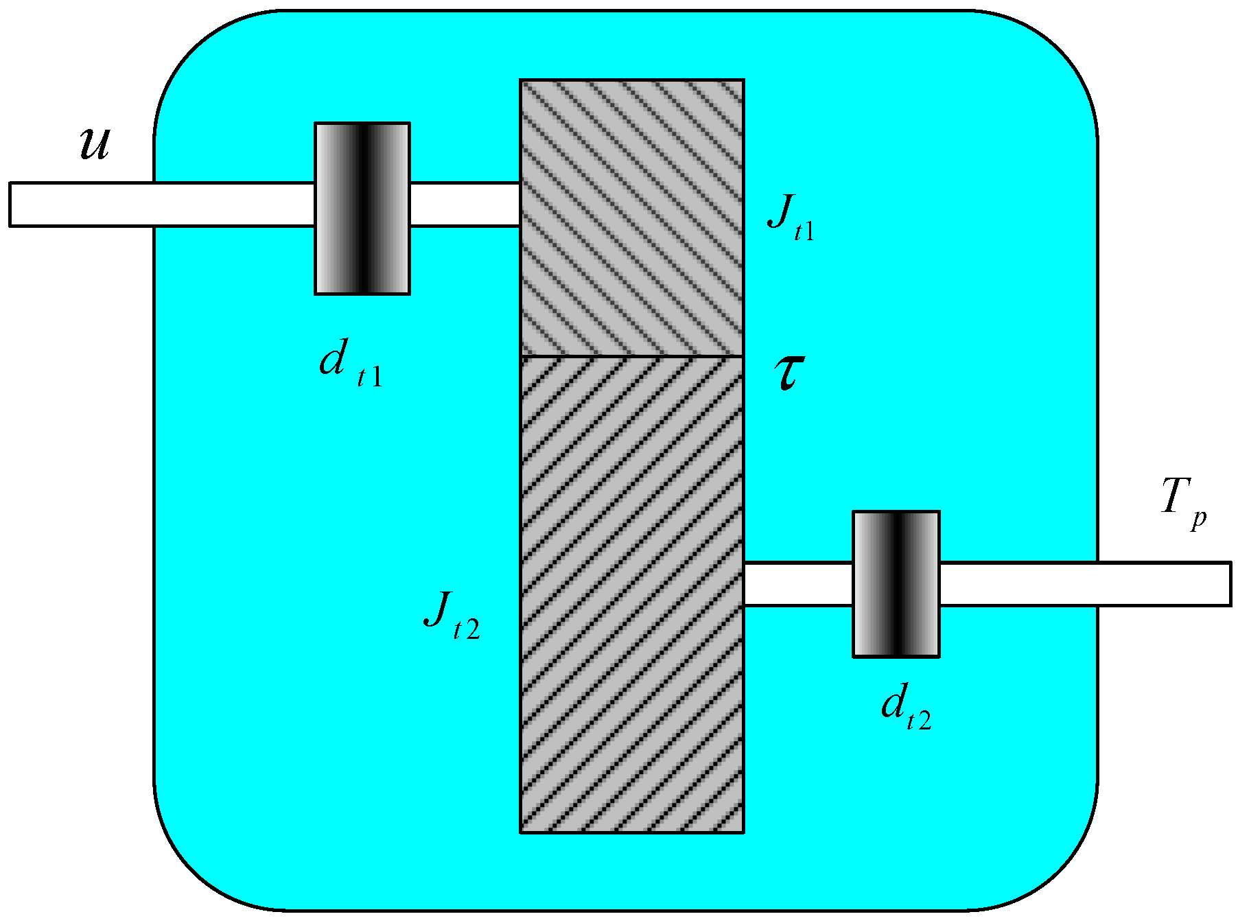
Active control of oscillation for shifting unloads motor torque dynamically rather than directly, until it is suitable for detaching the meshed gears, it will introduce much less motion oscillation. Therefore, minimization of the torque τ of meshed gears is selected as control objective of this controller. Figure 5 shows a simplified transmission model, where damping is considered in input and output shafts, with and , respectively.
For each gear shaft in transmission above, dynamic equation with transmission torque can be obtained as follows.
Combining them with the drive shaft dynamic Equation (5), Equation (6) can be transformed. The specific process of derivation can be seen in [32]:
where
The objective of the control system is to minimize the deviation between torque in meshed gears and the desirable reference value; should be reduced to zero before gear change begins in order to ensure smooth and quick shifting, so the reference value is 0. However, the response time should not be as short as possible, because quite a short response time always introduce a large overshoot, so a reasonable compromise is necessary. The cost function can be extended as (8). The second term indicates deviation between the control signal and the reference , is introduced as a trade-off between response time and large deviations of control signal (overshoot). It is the variable to be optimized.
can be derived as shown in Equation (9) by setting .
where
However, Equation (1) is an affine system because of the constant term [32], in order to obtain an optimal feedback unit based on LQR algorithm, Equation (1) should be linearized in the area near the equilibrium point, and the linearized state space equation is given in Equation (11).
where , , , . and are the initial values of and respectively, and considering the Equation (6), Equation (8) can be transformed into Equation (12).
where , . Based on Equation (1), the model of the drivetrain is augmented into Equation (13), should be small enough so that is a slow-varying value, i.e., , , and the linearized system will be stable.
So the cost function (12) can is augmented as Equation (14).
where
In order to minimize the Equation (14), the optimal feedback unit shown in Equation (17) is obtained based on LQR algorithm.
where is the solution of the Riccati Equation shown as Equation (18).
Therefore, the output of the controller, torque command of the motor , can be obtained ultimately as the following equations.
where
with
One of the main challenges of the LQR or any model-based approach is the model accuracy. How does the model behave against model parameters changing is discussed in Appendix A and stability of the designed controller against model parameter is discussed in Appendix B.
3.2. Off-Line Optimization with Real-Coded Genetic Algorithm
The critical parameter, , in designing the LQR controller acts as the weighting matrix, and it effects the performance of controller directly. Typically, the choice of this parameter mainly depends on the designer’s experience; such a subjective choice cannot guarantee an optimal result, and it may even introduce unknown side effects. In this article, the most appropriate value of is calculated off line by genetic algorithm in order to seek possible optimal solutions to the problem. Genetic algorithm is an effective research technique based on the rules of natural selection and genetics. By genetic operations such as reproduction, crossover and mutation [33], it simulates the mechanism of survival competitions, the superior results survive while the inferior results are eliminated. GA has been applied to many kinds of optimization issues in engineering, due to its simple and effective implementation procedure [34,35]. In order to unload torque in transmission with less oscillation in drivetrain, root mean square (RMS) of motor speed, torsional angle and rotary speed of drive shaft are introduced to constitute the fitness function, as their unit and magnitude are different, so that the above three indexes are normalized to be the fitness function , the optimization objectives can be expressed as Equation (23) where is open-loop drivetrain system state variable, is amount of sample points.
with , .
4. Results and Discussion
The proposed anti-oscillation active control algorithm is tested on a business software AMEsim®, with identical sample time of MATLAB. A drivetrain model is established on AMEsim® based on parameters and drivetrain structure of an electric vehicle, and parameters of controller is calculated and optimized by MATLAB off-line. The performance of optimized system is compared with unloading motor torque directly and other arbitrary parameters. In order to make the simulation test more realistic, external characteristic of permanent magnet synchronous motor (PMSM) is considered, as shown in Figure 7, which limits the torque command according to the peak torque limit, and the efficiency map related to energy consumption; also, while it is not discussed in this article, some critical parameters are shown in Table 3.
The critical parameters are listed as the following Table 4.
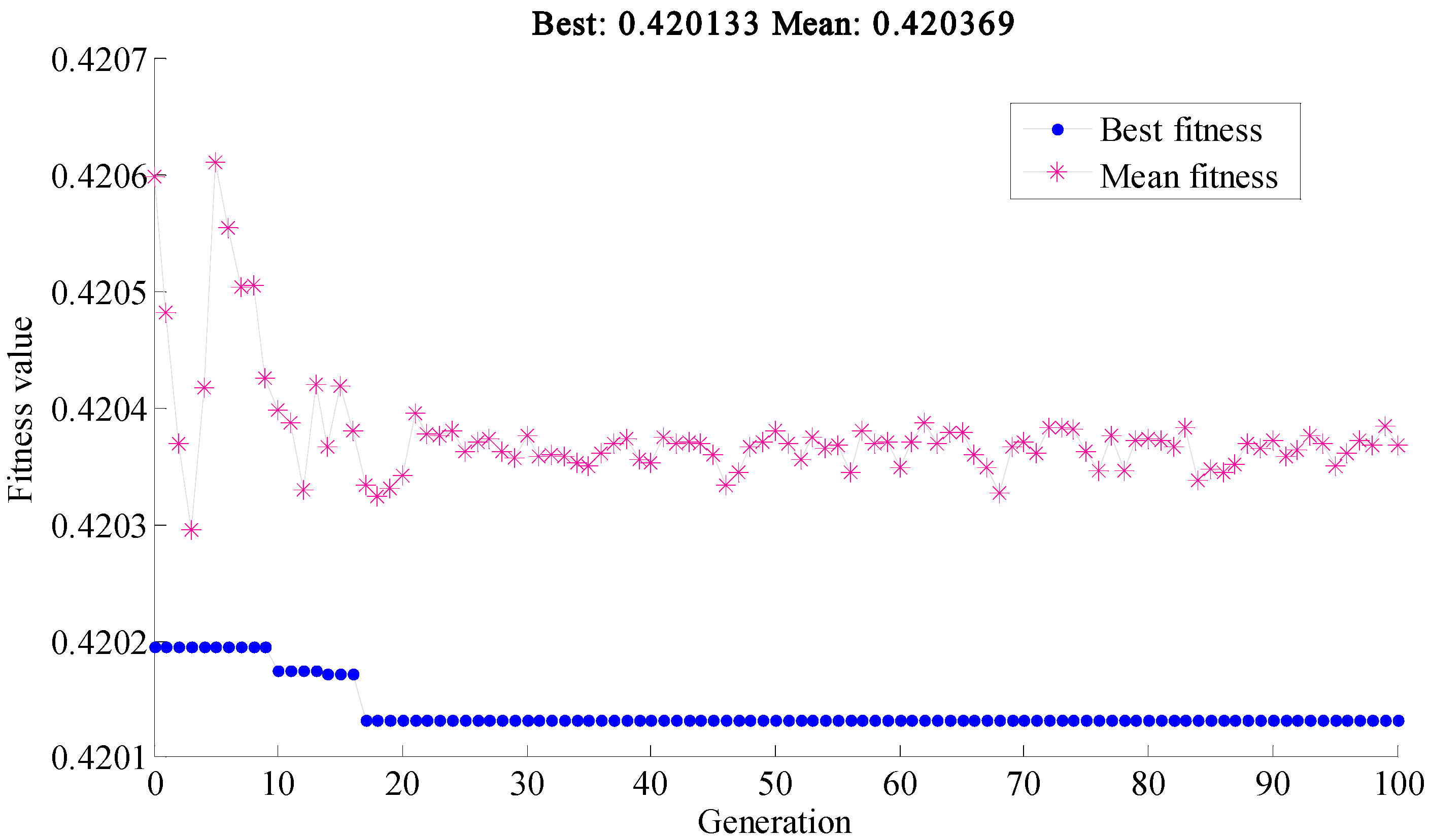
The test is conducted on the condition when the AMT receive a signal of shifting in the 3rd second, the motor is triggered to unload torque dynamically from initial 80 Nm as normal driving force. The first gear engaged is considered for instance, drag torque is set to 60 Nm constantly. Figure 8 shows the process of evolution of 100 generations. Because the optimization is quite time-consuming, this searching for the optimal parameter is finished off-line. The optimal will be searched out if the fitness namely fitness function reaches the minimum value. The pink mark is average fitness function of a population with 100 individuals in one generation, and the blued mark is the corresponding best fitness function value. From Figure 8, it can be observed that after revolution of about 20 generations, the best fitness is getting convergent and keep stable, so optimization results of the fitness function with the optimized is obtained. The optimal feedback gains is shown as follows.
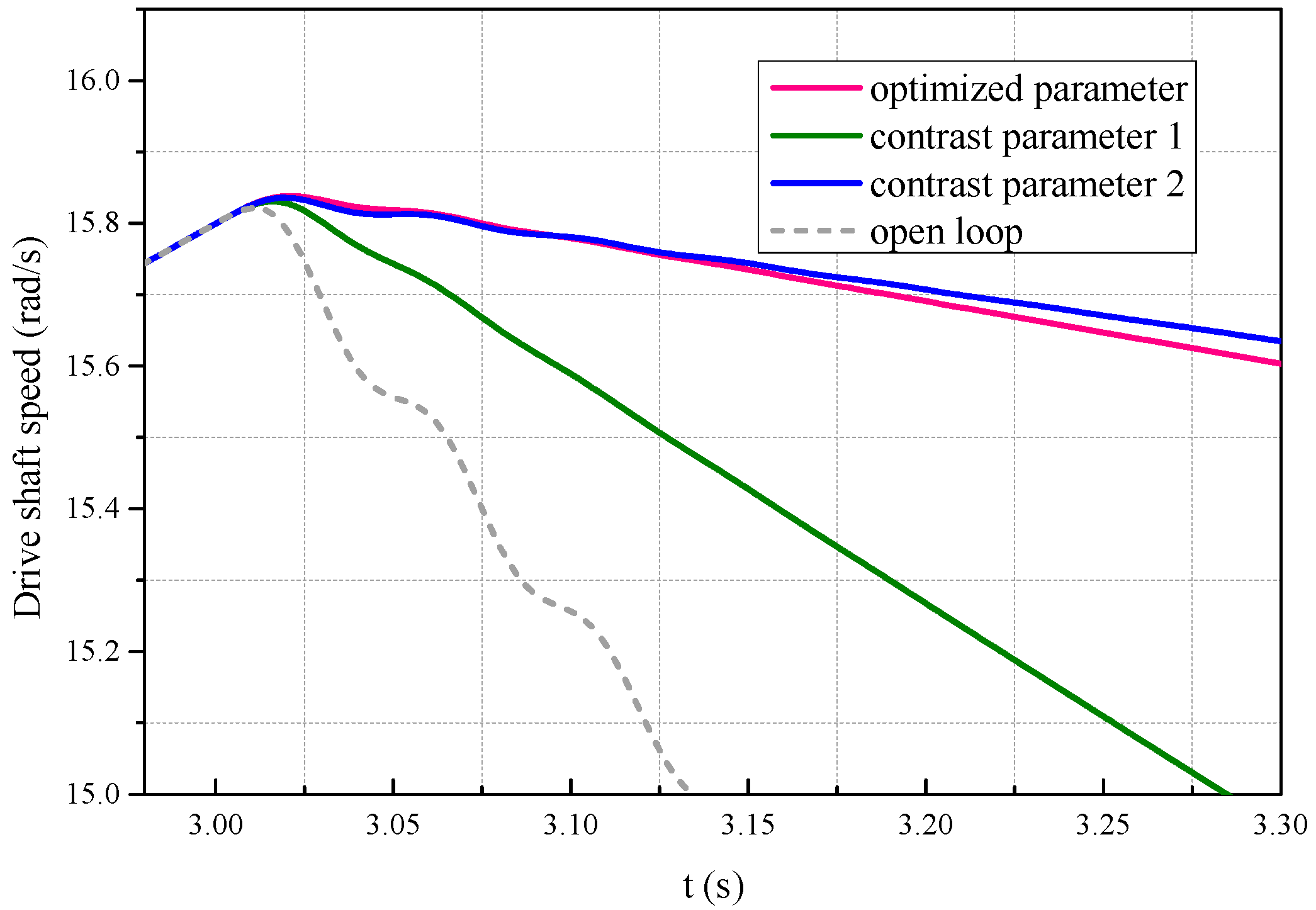
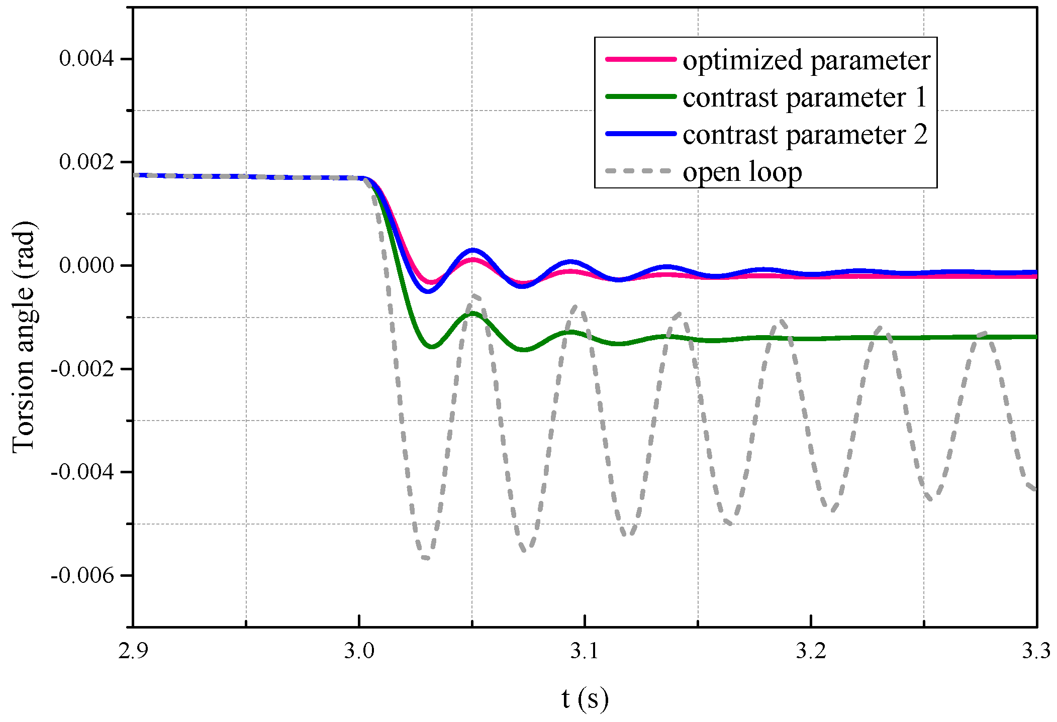
As a result of the physical characteristics of the motor, such as inertia of motor rotor, the torque output cannot actually be identical with the torque command as shown in Figure 9. It can be observed that motor torque output decreases dynamically instead of decreasing to zero directly, and friction moment, damping moment, inertia moment etc. are surmounted to decrease transmission torque , steady-state torque value compensates for large load torques due to losses and inertia. Figure 10 and Figure 11 illustrate motor speed oscillations and drive shaft speed oscillations respectively, Figure 12 shows the torsion angle of drive shaft. Contrast results with arbitrary contrast parameter 1 and contrast parameter 2 are introduced. Compared with open loop, EV drivetrain system with optimal feedback unit performs much better with few speed and torsion angle oscillations, the one with optimized parameter performs the best.
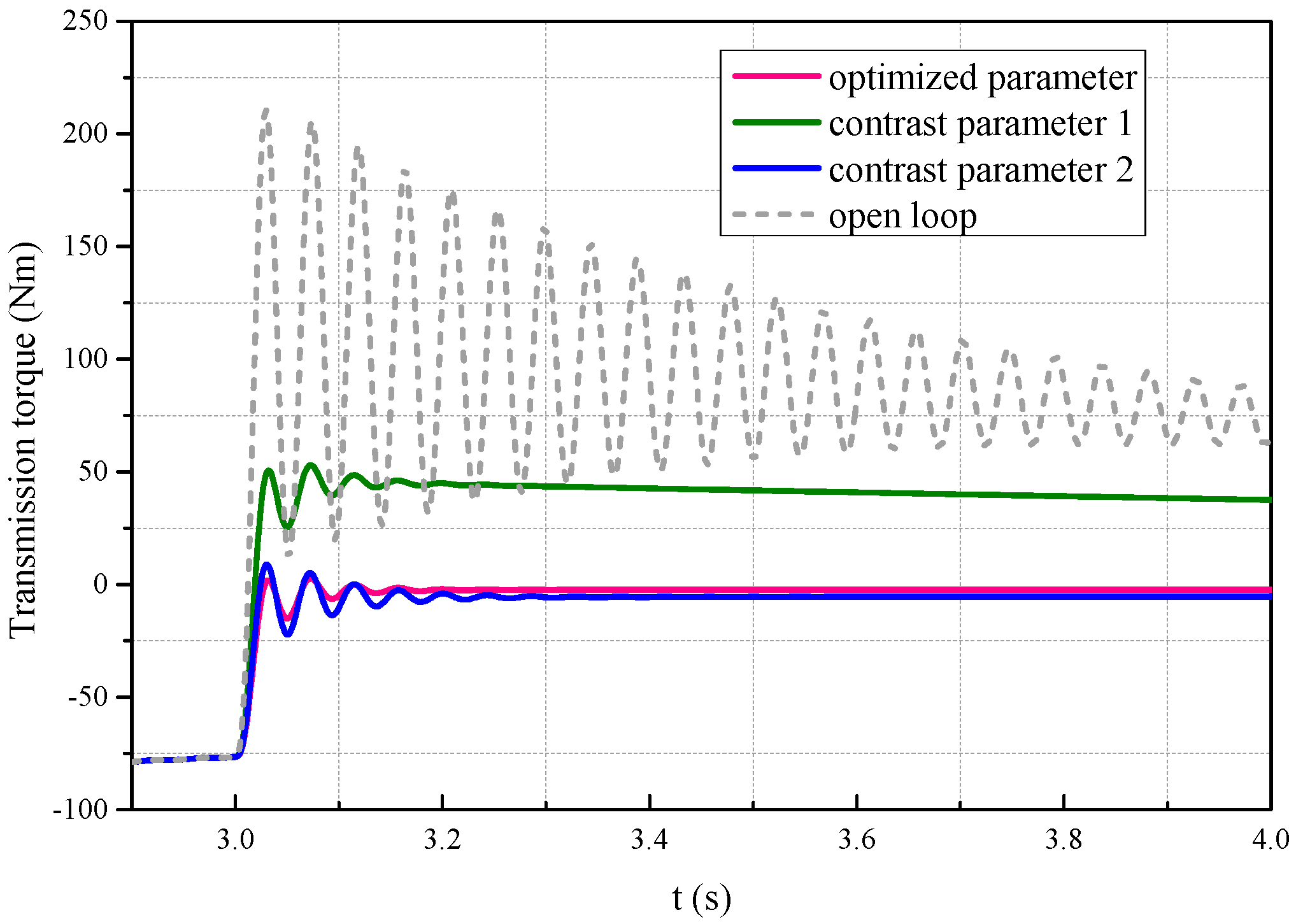
In Figure 13, transmission torque with the three configurations are compared. It can be observed that the transmission torque decreases to zero dynamically after the motor torque is unloaded. The open-loop system takes the longest time to converge to zero with the most oscillations. The optimal feedback units significantly improve over these results with the transmission torque reducing to zero much faster with less oscillations. The optimized parameter performs better than that with contrast parameter, demonstrating that the off-line optimization unit works effectively.
5. Conclusions and Future Work
The drivetrain of electric vehicles is quite different from that of conventional vehicles, with no clutch or no torque converter to interrupt torque transmission and buffer oscillation during gear shifting. Fortunately, the motor installed in electric vehicles has many advantages, such as being easily controlled and with quick response. This makes it possible to realize active attenuation for oscillation by controlling motor torque. This paper presents an active control method with off-line optimization to unload torque into transmission for gear shifting. Based on the linearized affine EV drivetrain dynamic model, linear quadratic regulator is applied to calculate an active torque to compensate speed oscillation, an off-line optimization unit with joint real-coded genetic algorithm is introduced to search the best weighting parameter of the optimal controller. Test results illustrate that by applying the presented method, torque in meshed gears will be reduced to zero rapidly for gear shifting, and less speed oscillations in the drivetrain will occur during the process of gear change. Therefore, shifting quality is improved, as compared with open-loop control and non-optimal solutions.
The proposed control method will be tested on a test rig and real electric vehicle in future; communication between the motor control unit (MCU) and the transmission control unit (TCU) by Controller Area Network (CAN) bus will be established in the next stage work.
Acknowledgments
This work was supported by the National Natural Science Foundation of China (grant number: 51575044).
Author Contributions
Cheng Lin supported this article financially; Shengxiong Sun conceived this control method for EV drivetrain, performed numerical simulation and completed the article; Paul Walker contributed to language revising and theoretical analysis; Nong Zhang contributed to theoretical analysis and theoretical guidance.
Conflicts of Interest
The authors declare no conflict of interest.
Appendix A
In this model, is rotational inertia of motor rotor, is gear ratio, they are fixed as constant values. is torsional stiffness of driveshaft. Because there could not be much deformation in driveshaft and it will not be beyond the proportional limit as typical shear stress-strain curve shows. Therefore, it is reasonable to regard the torsional stiffness as constant value. Similarly, are damping of some parts of the EV drivetrains, they are considered as constant values as well, as in all the relevant references of this article.
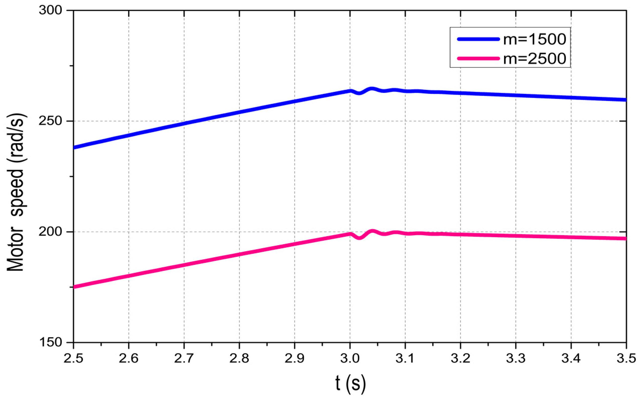
The only left parameter of the model is the , the equivalent rotational inertia of vehicle body, which may change a lot with different loading. In this article, m is supposed to be 1500 kg () as an empty loading, and here we introduce m = 2500 kg () as full loading for contrast.
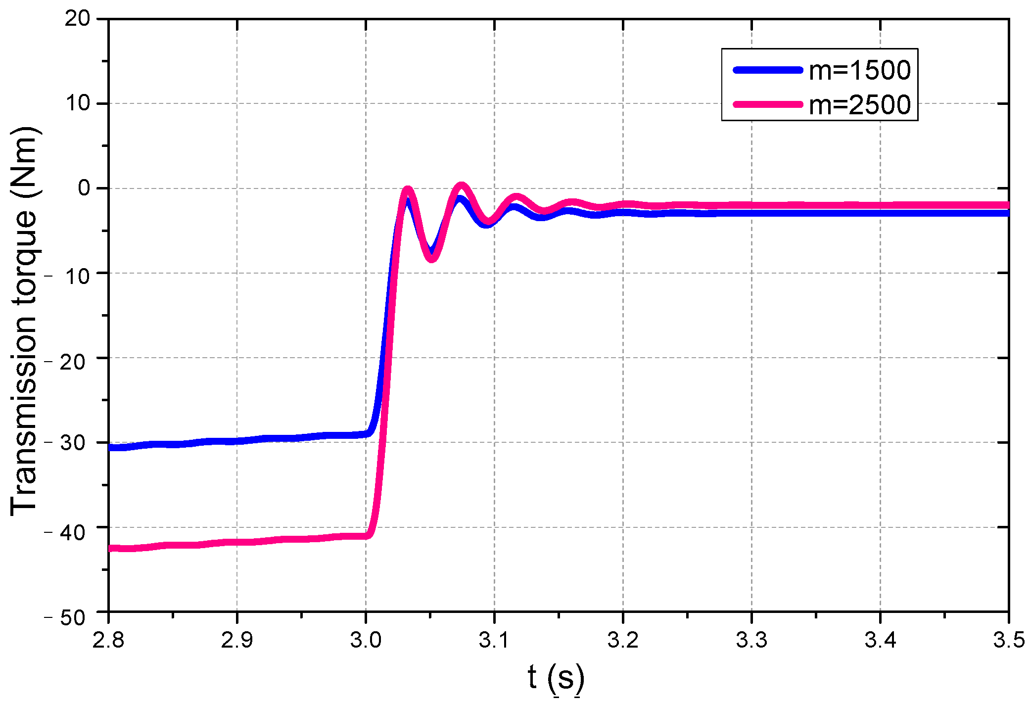
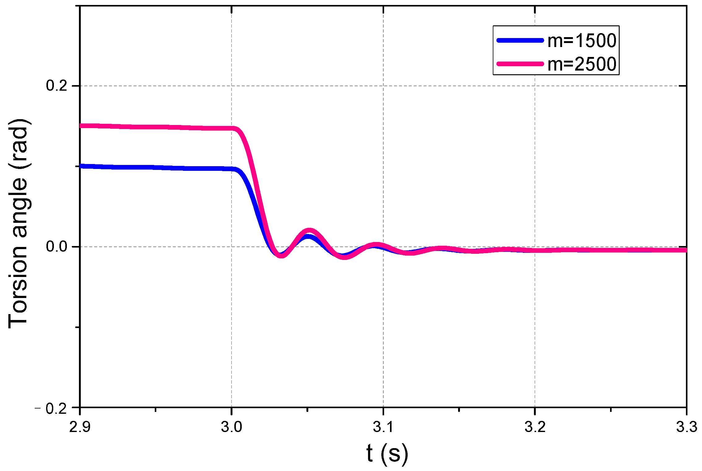
Figure A1, Figure A2, Figure A3 and Figure A4 illustrate performance comparisons of empty loading (m = 1500 kg) and performance of full loading (m = 2500 kg). In the above figures, the proposed controller still works regularly. Transmission torque can be decreased close to 0 dynamically and oscillations are kept in almost the same level. Fortunately, this controller seems not vulnerable to variation of rotational inertia of vehicle body, therefore, this application of LQR is not effected by variation of parameters so much.
The last but not least, there is error of transmission torque from 0, that is because the optimal feedbacks are calculated by matlab based on the exacted dynamic model and it is tested in AMEsim®, and we considered as many influential factors as possible to make the test approximate a real test, so the test results may deviate from the ideal result inevitably.
Figure A1.
Motor speed oscillations.

Figure A2.
Shaft speed oscillations.
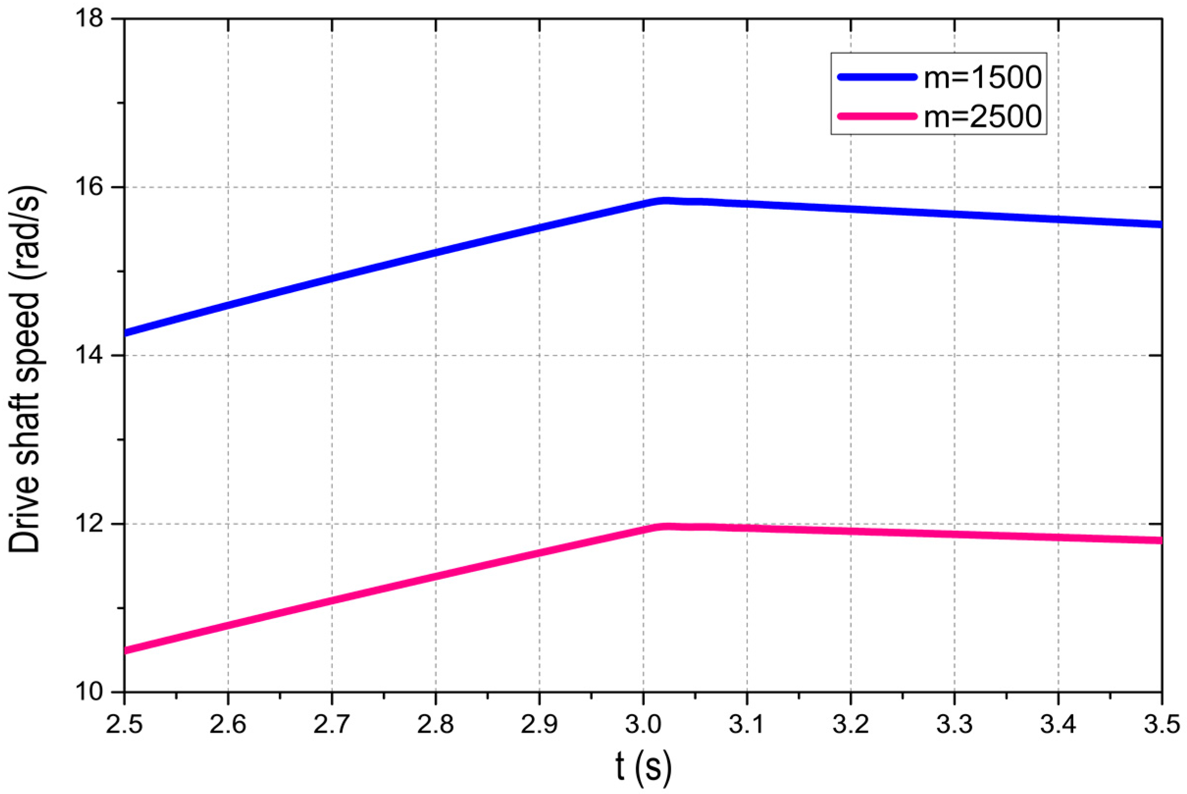
Figure A3.
Torsion angle of the drive shaft.

Figure A4.
Transmission torque .
Appendix B
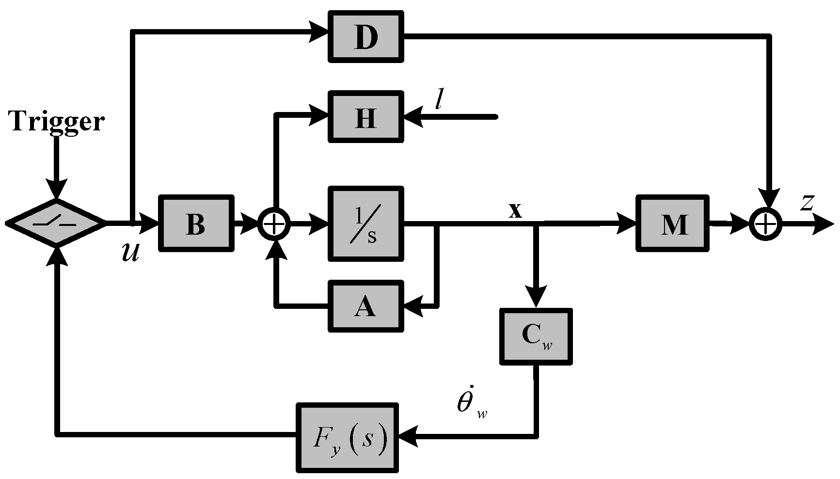
Figure A5 shows the diagram of the control system. Wheel speed is selected as feedback and then , , the others are identical to those in the submitted article. As parameter variations and disturbances may effect motor torque, and are mainly discussed, where , .
Figure A5.
Diagram of the control system.

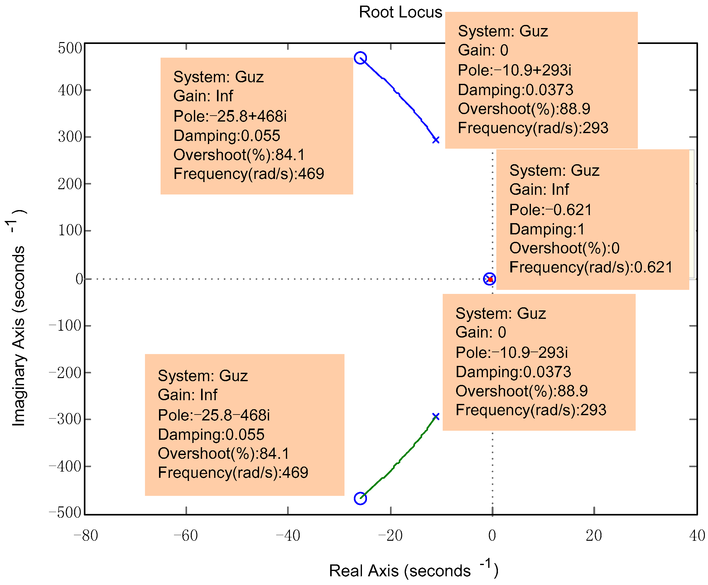
Figure A6 and Figure A7 show root locus using wheel speed feedback and using transmission torque feedback respectively. In the following figure it can be observed that all the roots are in the negative part of the coordinate, therefore, this system is stable.
Figure A6.
Root locus of .
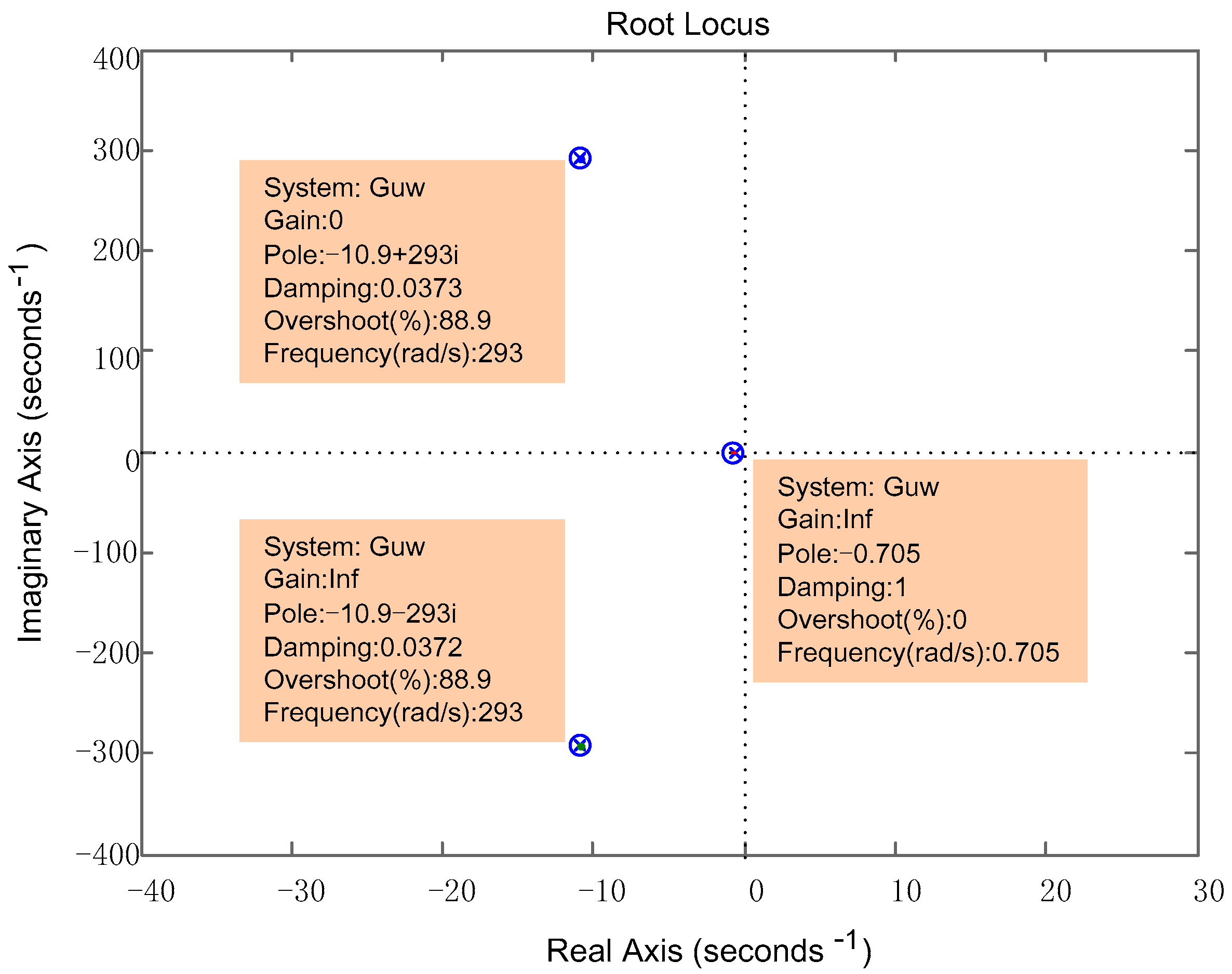
Figure A7.
Root locus of transmission torque .

The sensitivity of system using wheel speed feedback is expressed as
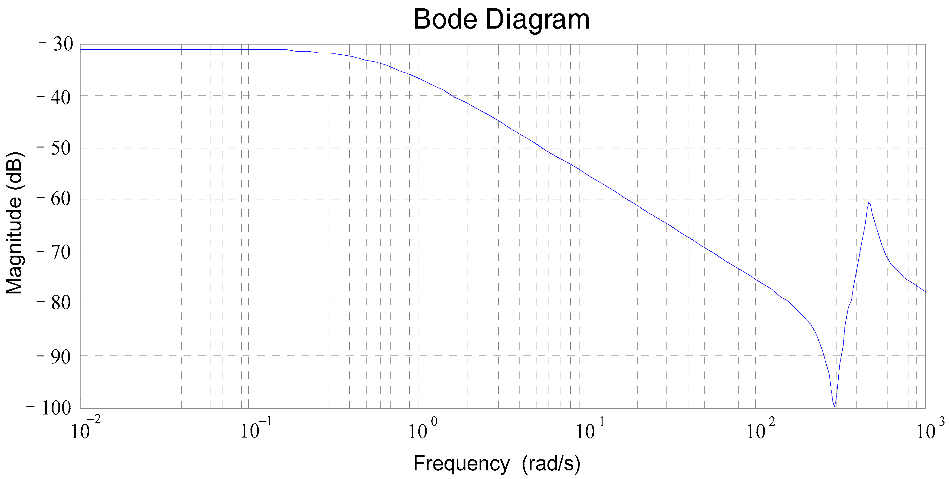
The sensitivity of system using transmission torque feedback is expressed as
Figure A8.
Sensitivity of system using wheel speed feedback.

Figure A9.
Sensitivity of system using transmission torque feedback.
Combining with Appendix A, rotational inertia of motor rotor, torsional stiffness and damping are considered as constant values, equivalent rotational inertia of vehicle body varies in quite a limited range and quite a limited frequency during regular operation. Therefore, it is still reasonable to apply LQR to active control system for EV drivetrains, although LQR may be effected by parameters variation.
References
- Shin, M.; Kim, H.; Kim, H.; Jang, H. Building an interoperability test system for electric vehicle chargers based on iso/iec 15118 and iec 61850 standards. Appl. Sci. 2016, 6, 165. [Google Scholar] [CrossRef]
- Llaria, A.; Terrasson, G.; Curea, O.; Jiménez, J. Application of wireless sensor and actuator networks to achieve intelligent microgrids: A promising approach towards a global smart grid deployment. Appl. Sci. 2016, 6, 61. [Google Scholar] [CrossRef]
- Chan, C.C.; Chau, K. An overview of power electronics in electric vehicles. IEEE Trans. Ind. Electron. 1997, 44, 3–13. [Google Scholar] [CrossRef] [Green Version]
- Walker, P.D.; Fang, Y.; Zhang, N. Dynamics and control of clutchless automated manual transmissions for electric vehicles. J. Vib. Acoust. 2017, 139, 061005. [Google Scholar] [CrossRef]
- Theodossiades, S.; Tangasawi, O.; Rahnejat, H. Gear teeth impacts in hydrodynamic conjunctions promoting idle gear rattle. J. Sound Vib. 2007, 303, 632–658. [Google Scholar] [CrossRef] [Green Version]
- Haris, A.; Motato, E.; Theodossiades, S.; Rahnejat, H.; Kelly, P.; Vakakis, A.; Bergman, L.A.; McFarland, D.M. A study on torsional vibration attenuation in automotive drivetrains using absorbers with smooth and non-smooth nonlinearities. Appl. Math. Model. 2017, 46, 674–690. [Google Scholar] [CrossRef]
- Zhang, L.; Si, Y.; Yu, Z. Numerical investigation into nonlinear dynamical characteristics of fuel cell vehicle powertrain system. Chin. J. Mech. Eng. 2009, 45, 62–67. [Google Scholar] [CrossRef]
- Pettersson, M.; Nielsen, L. Gear shifting by engine control. IEEE Trans. Control Syst. Technol. 2000, 8, 495–507. [Google Scholar] [CrossRef]
- Pham, T.; Bushnell, L. Two-degree-of-freedom damping control of driveline oscillations caused by pedal tip-in maneuver. In Proceedings of the American Control Conference (ACC) 2015, Chicago, IL, USA, 1–3 July 2015; pp. 1425–1432. [Google Scholar]
- Berriri, M.; Chevrel, P.; Lefebvre, D. Active damping of automotive powertrain oscillations by a partial torque compensator. Control Eng. Pract. 2008, 16, 874–883. [Google Scholar] [CrossRef]
- Fredriksson, J.; Weiefors, H.; Egardt, B. Powertrain control for active damping of driveline oscillations. Veh. Syst. Dyn. 2002, 37, 359–376. [Google Scholar] [CrossRef]
- Baumann, J.; Torkzadeh, D.D.; Ramstein, A.; Kiencke, U.; Schlegl, T. Model-based predictive anti-jerk control. Control Eng. Pract. 2006, 14, 259–266. [Google Scholar] [CrossRef]
- Caruntu, C.F.; Balau, A.E.; Lazar, M.; Bosch, P.P.; Di Cairano, S. Driveline oscillations damping: A tractable predictive control solution based on a piecewise affine model. Nonlinear Anal. Hybrid Syst. 2016, 19, 168–185. [Google Scholar] [CrossRef]
- Lefebvre, D.; Chevrel, P.; Richard, S. An h-infinity-based control design methodology dedicated to the active control of vehicle longitudinal oscillations. IEEE Trans. Control Syst. Technol. 2003, 11, 948–956. [Google Scholar] [CrossRef]
- Siami, M.; Khaburi, D.A.; Rivera, M.; Rodríguez, J. An experimental evaluation of predictive current control and predictive torque control for a pmsm fed by a matrix converter. IEEE Trans. Ind. Electron. 2017, 64, 8459–8471. [Google Scholar] [CrossRef]
- Wang, Y.; Wang, X.; Xie, W.; Wang, F.; Dou, M.; Kennel, R.M.; Lorenz, R.D.; Gerling, D. Deadbeat model-predictive torque control with discrete space-vector modulation for pmsm drives. IEEE Trans. Ind. Electron. 2017, 64, 3537–3547. [Google Scholar] [CrossRef]
- Yang, H.; Zhang, Y.; Yuan, G.; Walker, P.D.; Zhang, N. Hybrid synchronized pwm schemes for closed-loop current control of high-power motor drives. IEEE Trans. Ind. Electron. 2017, 64, 6920–6929. [Google Scholar] [CrossRef]
- Kommuri, S.K.; Defoort, M.; Karimi, H.R.; Veluvolu, K.C. A robust observer-based sensor fault-tolerant control for pmsm in electric vehicles. IEEE Trans. Ind. Electron. 2016, 63, 7671–7681. [Google Scholar] [CrossRef]
- Song, Z.; Li, J.; Shuai, Z.; Xu, L.; Ouyang, M. Fuzzy logic torque control system in four-wheel-drive electric vehicles for active damping vibration control. Int. J. Veh. Des. 2015, 68, 55–80. [Google Scholar] [CrossRef]
- Bang, J.S.; Ko, Y.-K.; Jung, T.-H. The Active Damping Control to Reduce Driveline Oscillations for Electric Vehicles Using Wheel Speeds; SAE Technical Paper 0148-7191; SAE: Detroit, MI, USA, 2015. [Google Scholar]
- Orlowska-Kowalska, T.; Szabat, K. Damping of torsional vibrations in two-mass system using adaptive sliding neuro-fuzzy approach. IEEE Trans. Ind. Inform. 2008, 4, 47–57. [Google Scholar] [CrossRef]
- Lv, C.; Zhang, J.; Li, Y.; Yuan, Y. Mode-switching-based active control of a powertrain system with non-linear backlash and flexibility for an electric vehicle during regenerative deceleration. Proc. Inst. Mech. Eng. D J. Automob. Eng. 2015, 229, 1429–1442. [Google Scholar] [CrossRef]
- Fu, H.; Tian, G.; Chen, H.A.; University, C.Q. A study on the torsional vibration control of motor-transmission integrated drive system. Automot. Eng. 2010, 32, 597–600. [Google Scholar]
- Roy, T.; Chakraborty, D. Optimal vibration control of smart fiber reinforced composite shell structures using improved genetic algorithm. J. Sound Vib. 2009, 319, 15–40. [Google Scholar] [CrossRef]
- Zhang, Y.; Chen, Z.; Jiao, Y. A hybrid vibration isolator: Design, control, and experiments. Proc. Inst. Mech. Eng. C J. Mech. Eng. Sci. 2016, 230, 2982–2995. [Google Scholar] [CrossRef]
- Prabakar, R.S.; Sujatha, C.; Narayanan, S. Response of a half-car model with optimal magnetorheological damper parameters. J. Vib. Control 2016, 22, 784–798. [Google Scholar] [CrossRef]
- Nagarkar, M.; Vikhe, G. Optimization of the linear quadratic regulator (LQR) control quarter car suspension system using genetic algorithm. Ing. Investig. 2016, 36, 23–30. [Google Scholar] [CrossRef]
- Das, S.; Pan, I.; Das, S. Multi-objective lqr with optimum weight selection to design fopid controllers for delayed fractional order processes. ISA Trans. 2015, 58, 35–49. [Google Scholar] [CrossRef] [PubMed]
- Ufnalski, B.; Kaszewski, A.; Grzesiak, L.M. Particle swarm optimization of the multioscillatory lqr for a three-phase four-wire voltage-source inverter with an LC output filter. IEEE Trans. Ind. Electron. 2015, 62, 484–493. [Google Scholar] [CrossRef]
- Yu, S.; Dong, G.; Li, L. Transient characteristics of emissions during engine start/stop operation employing a conventional gasoline engine for HEV application. Int. J. Automot. Technol. 2008, 9, 543–549. [Google Scholar] [CrossRef]
- Mitschke, M.; Wallentowitz, H. Dynamik der Kraftfahrzeuge; Springer: Berlin/Heidelberg, Germany, 2004. [Google Scholar]
- Kiencke, U.; Nielsen, L. Automotive Control Systems: For Engine, Driveline, and Vehicle; Springer: Berlin, Germany, 2005. [Google Scholar]
- Kuo, C.-C.; Liu, C.-H.; Chang, H.-C.; Lin, K.-J. Implementation of a motor diagnosis system for rotor failure using genetic algorithm and fuzzy classification. Appl. Sci. 2017, 7, 31. [Google Scholar] [CrossRef]
- Perez-Ramirez, C.; Jaen-Cuellar, A.; Valtierra-Rodriguez, M.; Dominguez-Gonzalez, A.; Osornio-Rios, R.; Romero-Troncoso, R.; Amezquita-Sanchez, J. A two-step strategy for system identification of civil structures for structural health monitoring using wavelet transform and genetic algorithms. Appl. Sci. 2017, 7, 111. [Google Scholar] [CrossRef]
- Cam, E.; Gorel, G.; Mamur, H. Use of the genetic algorithm-based fuzzy logic controller for load-frequency control in a two area interconnected power system. Appl. Sci. 2017, 7, 308. [Google Scholar] [CrossRef]
Figure 1.
Structure of rear-wheel-drive electric vehicle drivetrain with motor-transmission integrated system.
Figure 1.
Structure of rear-wheel-drive electric vehicle drivetrain with motor-transmission integrated system.
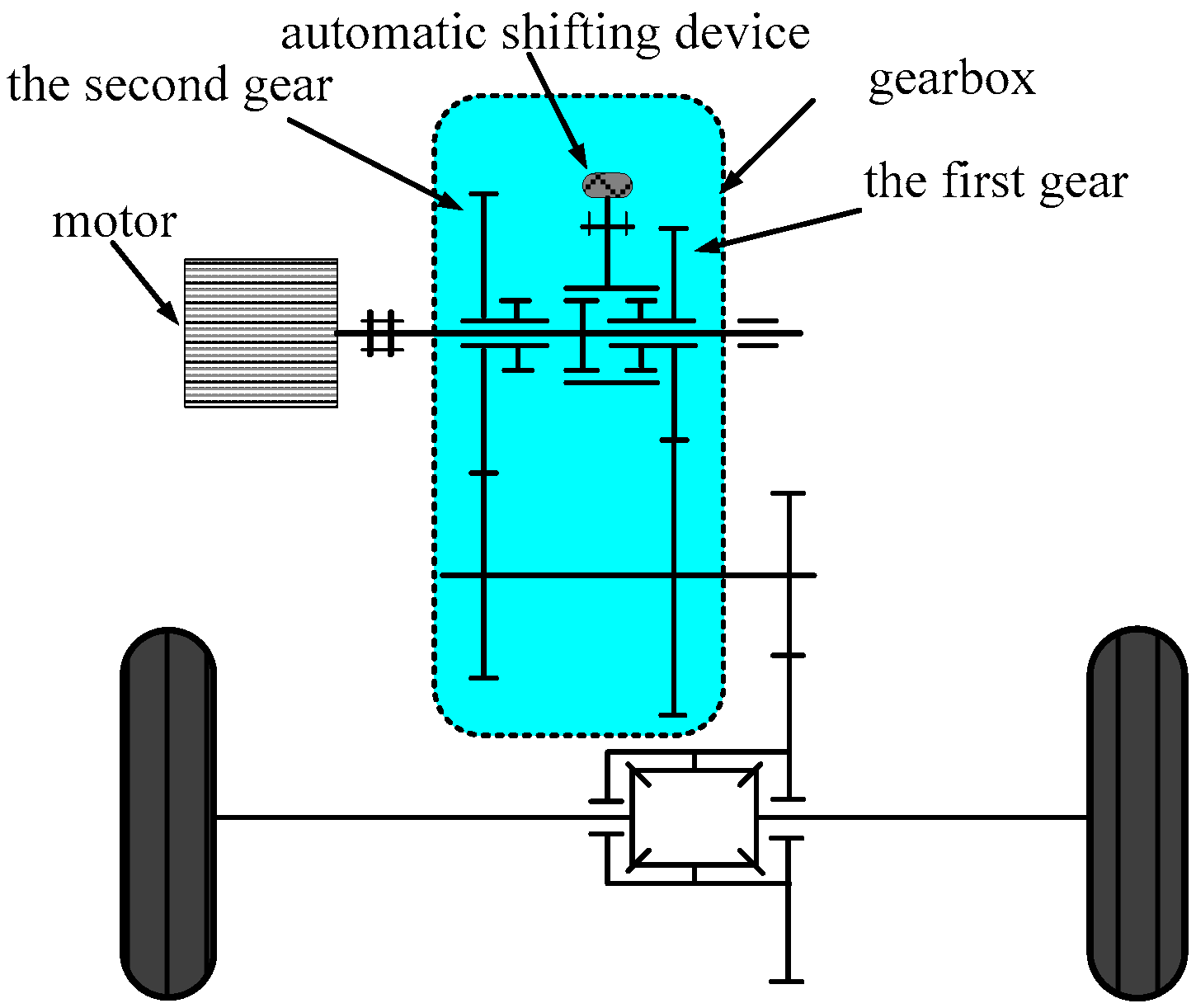
Figure 2.
Up and down shift transients for clutchless automated manual transmission (AMT) powertrain for a 20 ms stage duration at 200 Nm motor torque (a) system speeds, (b) vehicle longitudinal acceleration, and (c) vehicle longitudinal jerk.
Figure 2.
Up and down shift transients for clutchless automated manual transmission (AMT) powertrain for a 20 ms stage duration at 200 Nm motor torque (a) system speeds, (b) vehicle longitudinal acceleration, and (c) vehicle longitudinal jerk.

Figure 3.
Six degrees of the freedom model of electric vehicle (EV) drivetrain.

Figure 4.
Electric vehicle drivetrain model.
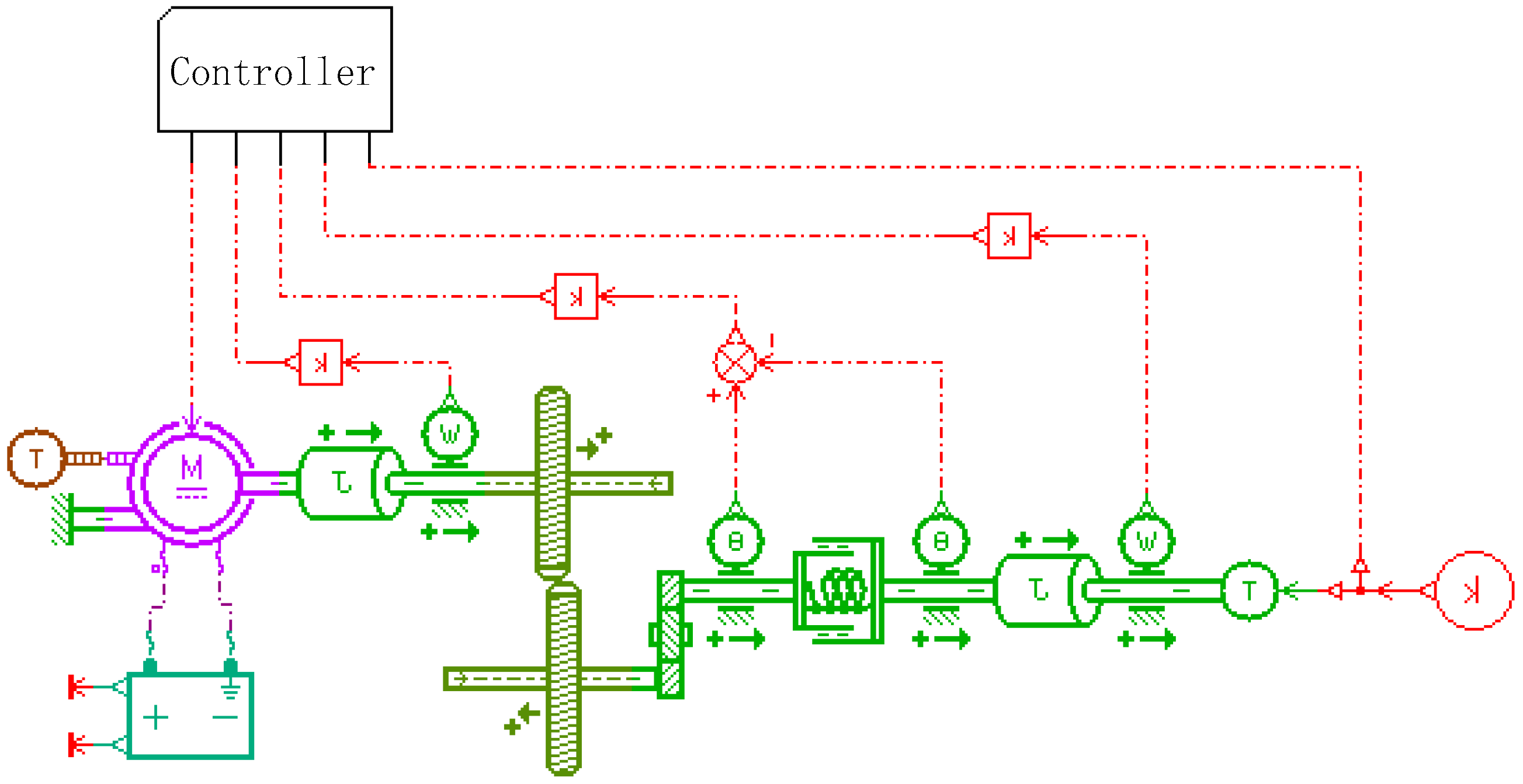
Figure 5.
Simplified transmission model.

Figure 6.
Structure of the active control system with off-line unit.

Figure 7.
External characteristic of permanent magnet synchronous motor.
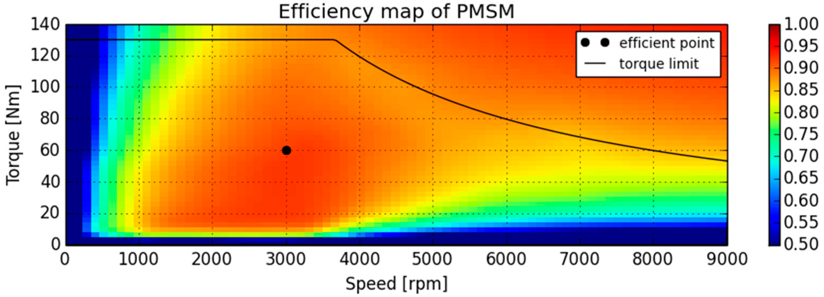
Figure 8.
Optimized fitness result.

Figure 9.
Torque output of permanent magnet synchronous motor (PMSM).
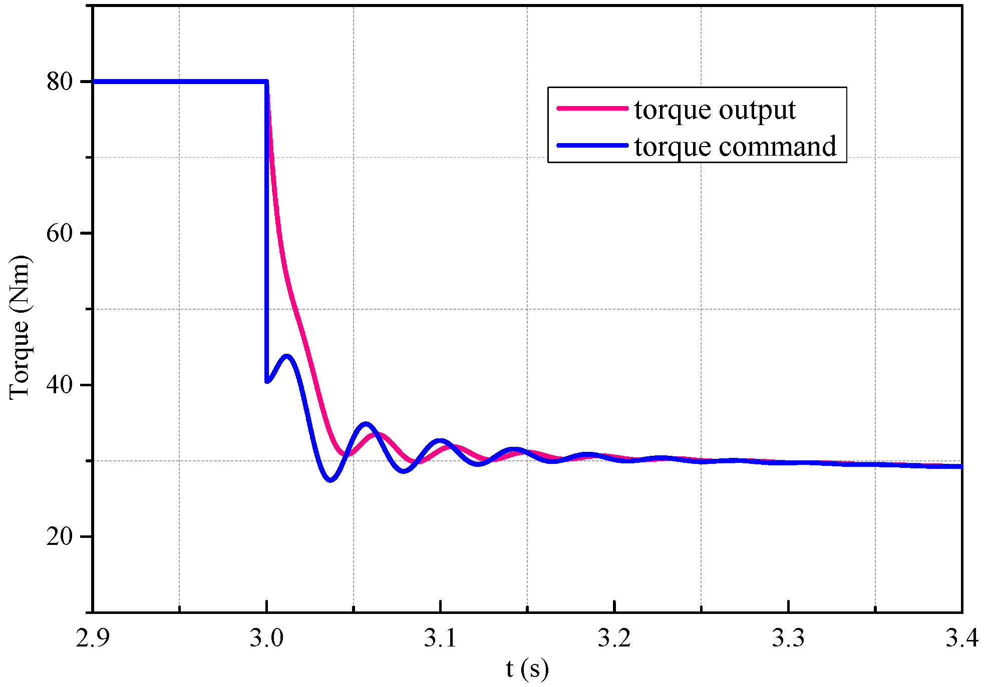
Figure 10.
Motor speed oscillations.
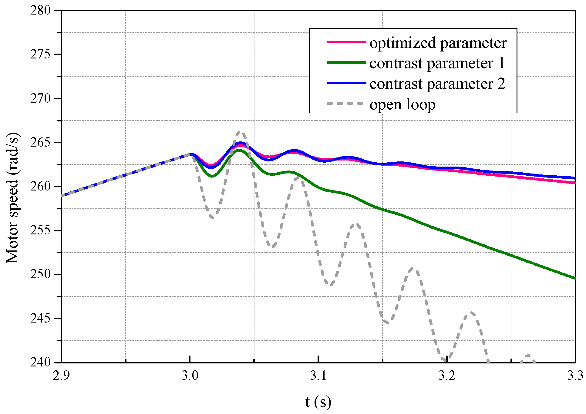
Figure 11.
Drive shaft speed oscillations.

Figure 12.
Torsion angle of drive shaft.

Figure 13.
Transmission torque .

Table 1.
Symbols and subscripts of electric vehicle (EV) drivetrain model cite.
| Symbols | Indication | Subscripts | Indication |
|---|---|---|---|
| mass moment of inertia | Motor | ||
| torsional stiffness | transmission | ||
| torsional damping | propeller shaft | ||
| gear ratio | final drive | ||
| torsion angle of drive shaft | drive shaft | ||
| torque include friction | wheel | ||
| resisting moment | - | - | |
| gross mass of vehicle | - | - | |
| wheel radius | - | - |
Table 2.
Configuration parameters of genetic algorithm (GA).
| Parameter | Configuration | Parameter | Configuration |
|---|---|---|---|
| Encoding | real code | Crossover Fraction | 0.4 |
| Population Size | 100 | Generations | 100 |
| Elite Amount | 10 | Mutation Function | constrained mutation |
Table 3.
Configuration parameters of permanent magnet synchronous motor (PMSM).
| Parameter | Configuration | Parameter | Configuration |
|---|---|---|---|
| maximum power | 60 kW | maximum torque | 150 Nm |
| maximum speed | 9000 rev/min | - | - |
Table 4.
Critical parameters of EV drivetrain.
| Parameter | Configuration | Parameter | Configuration |
|---|---|---|---|
| 1500 kg | 0.29 m | ||
| 3.4545 | 4.831 | ||
| 246,371 Nm/rad | 0.05 kg·m2 | ||
| 0.01055 kg·m2 | 128.15 kg·m2 | ||
| 9.549 Nm/(rad/s) | 0.2 Nm/(rad/s) | ||
| 31.17 Nm/(rad/s) | - | - |
© 2017 by the authors. Licensee MDPI, Basel, Switzerland. This article is an open access article distributed under the terms and conditions of the Creative Commons Attribution (CC BY) license (http://creativecommons.org/licenses/by/4.0/).
Share and Cite
MDPI and ACS Style
Lin, C.; Sun, S.; Walker, P.; Zhang, N. Off-Line Optimization Based Active Control of Torsional Oscillation for Electric Vehicle Drivetrain. Appl. Sci. 2017, 7, 1261. https://doi.org/10.3390/app7121261
AMA Style
Lin C, Sun S, Walker P, Zhang N. Off-Line Optimization Based Active Control of Torsional Oscillation for Electric Vehicle Drivetrain. Applied Sciences. 2017; 7(12):1261. https://doi.org/10.3390/app7121261
Chicago/Turabian StyleLin, Cheng, Shengxiong Sun, Paul Walker, and Nong Zhang. 2017. "Off-Line Optimization Based Active Control of Torsional Oscillation for Electric Vehicle Drivetrain" Applied Sciences 7, no. 12: 1261. https://doi.org/10.3390/app7121261
Note that from the first issue of 2016, this journal uses article numbers instead of page numbers. See further details here.