Article

Optimization Design of Coupling Beam Metal Damper in Shear Wall Structures

1
Faculty of Vehicle Engineering and Mechanics, Dalian University of Technology, State Key Laboratory of Structural Analysis for Industrial Equipment, Dalian 116024, China
2
Faculty of Infrastructure Engineering, Dalian University of Technology, Dalian 116024, China
3
Department of Mechanical Engineering, Penn State University, State College, PA 16802, USA
*
Author to whom correspondence should be addressed.
Appl. Sci. 2017, 7(2), 137; https://doi.org/10.3390/app7020137
Submission received: 10 November 2016 / Revised: 25 December 2016 / Accepted: 22 January 2017 / Published: 3 February 2017

Abstract

:
The coupling beam damper is a fundamental energy dissipation component in coupling shear wall structures that directly influences the performance of the shear wall. Here, we proposed a two-fold design method that can give better energy dissipation performance and hysteretic behavior to coupling beam dampers. First, we devised four in-plane yielding coupling beam dampers that have different opening types but the same amount of total materials. Then the geometry parameters of each opening type were optimized to yield the maximum hysteretic energy. The search for the optimal parameter set was realized by implementing the Kriging surrogate model which iterates randomly selected input shape parameters and the corresponding hysteretic energy calculated by the infinite element method. By comparing the maximum hysteretic energy in all four opening types, one type that had the highest hysteresis energy was selected as the optimized design. This optimized damper has the advantages of having a simple geometry and a high dissipation energy performance. The proposed method also provided a new framework for the design of in-plane coupling beam dampers.

1. Introduction

Based on the assumptions of ductility design, coupled shear wall structures should satisfy the features of a “strong wall with a weak coupling beam”. Such a setup will guarantee that a structure has enough stiffness to allow the shear wall to not fail first during rare earthquake events. In these scenarios, a plastic hinge would dissipate the energy and ensure that the shear wall will not yield too early. The ductility of coupling beams is one of the most important factors that influence the ultimate bearing capacity, and both shear force and deformation requirements should be met by a coupling beam under reciprocating load which occurs in earthquakes. A great deal of research has been done around the globe to explore approaches to satisfy the ductility requirements of shear wall beam structures.
Paulay et al. [1] improved the behavior of commonly-used reinforcement concrete using diagonal crossing reinforcement, which can remarkably improve anti-seismic features. Coull [2] proposed placing stiff coupling beams on the top of a shear wall structure in order to strengthen the structure’s integrity and to improve lateral stiffness. Kelly and Skinner et al. [3,4] raised the idea of metallic dampers, which, made out of metal, could have the advantage of the material’s plastic yield feature to dissipate earthquake energy inputs. Fortney et al. [5,6,7] developed the concept of a changeable steel coupling beam, which features a weakened middle part (namely the safety wire) that can dissipate energy via shear yielding and is easy to switch after damage. Chung et al. [8] used bending as a damper energy dissipative form and set up a frictional damping device in the middle of a coupling beam that can decrease the response of the shear wall structure during earthquakes. Kim et al. [9,10] developed a compound energy-dissipation damper, in which high-damping rubber material and two U-shaped steel plates were combined to acquire high energy dissipation. Lyons [11] developed a new type of visco-elasticity damper which could potentially replace the coupling beam damper. Mao et al. [12] proposed a new shape for memory alloy dampers that restore their original shape after damage, and do not require replacement as coupling beam dampers do. Although the above-mentioned designs of dampers have led to progress at some points, they also made the structure coupling beams complicated enough to hardly justify the improvements in the energy dissipation capacity. In addition, parameter optimization which can potentially improve damper performance is often overlooked in the design of coupling beam dampers.
To this end, we proposed a two-fold method for the design of a simple and easy-to-make metallic damper that features a high energy dissipation capability. Based on the existing dampers, four types of openings in the damper are developed and studied. A constitutive law is provided to establish the relationship between design parameters, including the opening size and thickness, and the energy dissipation capacity. A Kriging surrogate model is then introduced with a shuffled complex evolution (SCE) intelligent optimization algorithm to search the optimized design parameters that can lead to the maximum hysteresis energy. The proposed work can also be used as a platform for opening parameter design with high surrogate accuracy and global optimization efficiency.

2. Coupling Beam Metal Dampers

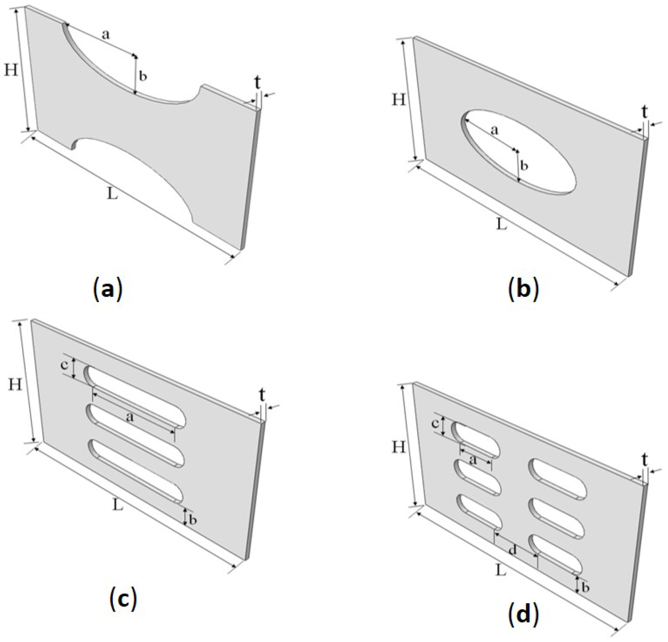
2.1. Typical Pores in Coupling Beam Metal Dampers

Following the principle of equivalent strength, large pores should open in the middle part of the slab with no weakening at the two ends. We chose the following four types of dampers with a length of 280 mm and a width of 160 mm, which can be seen in Figure 1. Based on the premise of equal materials of the same size, the limit boundary of the pore geometrical parameters can be determined using pore porosity limitations of 10%–25%. The four kinds of models are described as follows:
Plate with split elliptic pores (SP1). The independent variables are elliptical semi-major axis a and semi-minor axis b, and the dependent variable is the thickness of plate t; a is in the interval of 53.42 to 84.46 and b is in the interval of 26.71 to 42.23.
Plate with one central elliptic pore (SP2). The independent variables are elliptical semi-major axis a and semi-minor axis b, which have the same upper and lower bounds as SP1. The dependent variable is the thickness of plate t.
Plate with single column of uniform pores (SP3). The independent variables are the length of row pore a and the distance between two rows b, respectively. The dependent variables are the width of row pores c and the thickness of plate t; a is in the interval [74, 67, 118, 06] and b is in the interval [19, 87, 27, 26].
Plate with two columns of uniform pores (SP4). The distance between the two columns is fixed at 60 mm. The independent variables and the dependent variables are similar to those of SP3, where the range of a is reset to [30, 68, 48, 50].

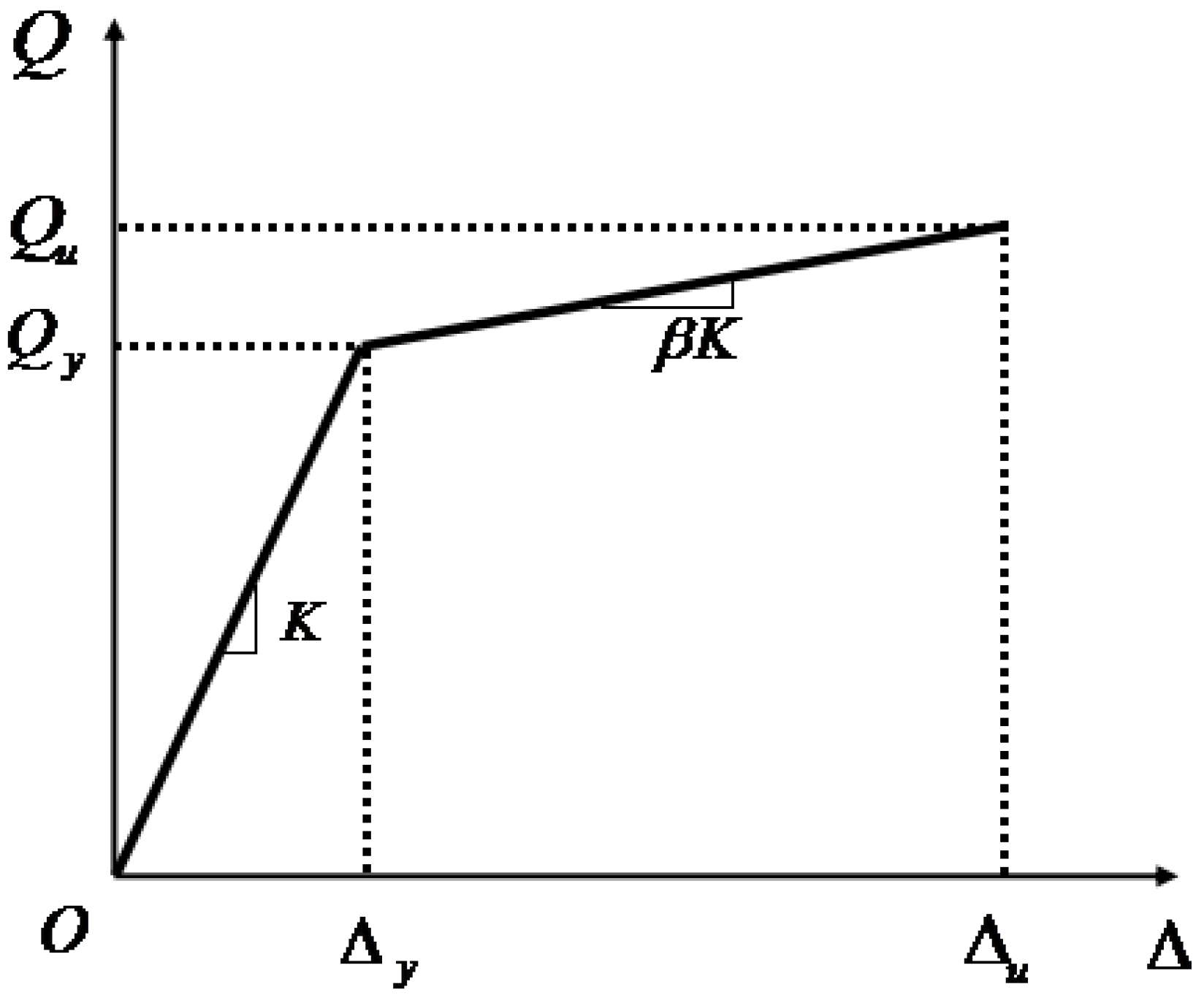
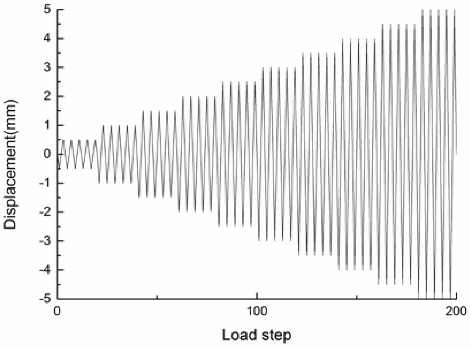
2.2. Hysteresis Energy Calculation

The bilinear kinematic hardening model of the material was used as shown in Figure 2. The elastic modulus was 2.07 × 10⁵ MPa, Poisson’s ratio was 0.3, and the yield strength was 235 MPa. The elastic modulus after yielding was 0.004 times that of the initial modulus. The component was fixed at the left end, and was freely constrained in the X (horizontal) and Z (out-of-plane) direction at the right end. Vertical displacement was applied in the Y direction, and the right end of the component was applied to the vertical reciprocating displacement. The incremental displacement was 5 mm to control the loading rate. Then cycles of loading were done in total and the maximum displacement was 50 mm, and the displacement load is shown in Figure 3.

3. The Relationship between Pore Geometrical Parameters and Hysteresis Energy

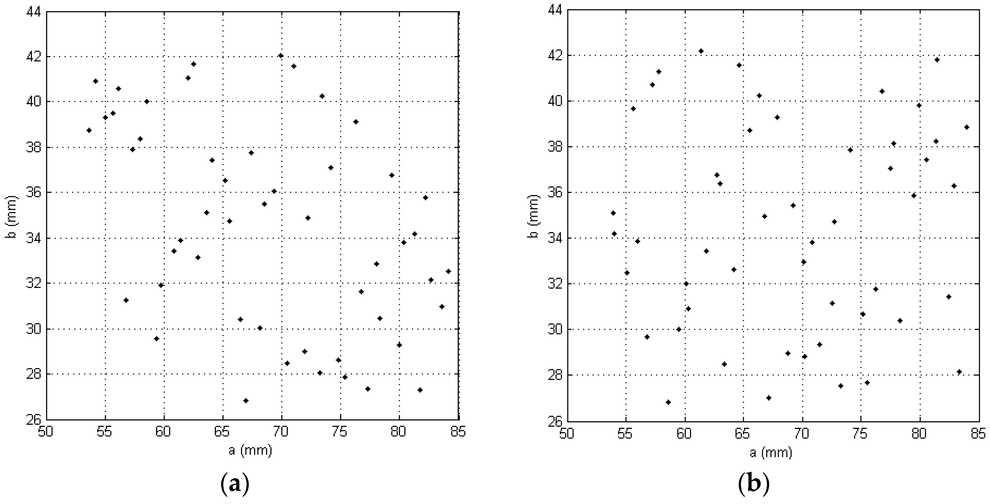
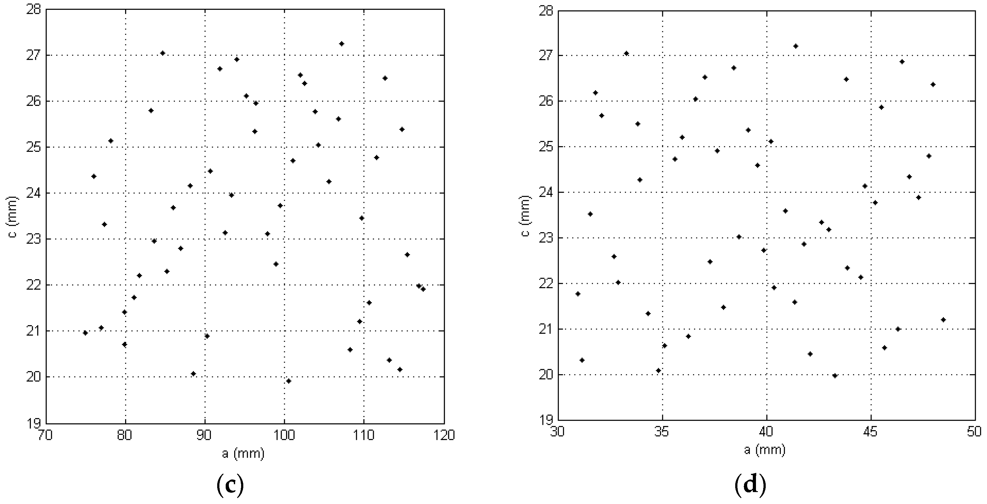
3.1. Sampling Selection

Fifty samples of the each kind of metal damper were selected using the Latin hypercube sampling method. Then, the dependent variables, c, in SP3 and SP4SP4 could be deduced under the precondition of equal materials being used which are of the same size:
c = ( 160 4 b ) / 3
For the plate with elliptic pores, the thickness could be calculated using the following equation:
t = A 280 × 160 π a b
in which A represents the total material, and a and b are the semi-major axis and semi-minor axis, respectively. For SP3 and SP4SP4, the thickness of the plate could be written as the following
t = A 280 × 160 3 ( a c + π ( c 2 ) 2 )
t = A 280 × 160 6 ( a c + π ( c 2 ) 2 )
The sampling results for each kind of metal damper are shown in Figure 4.

3.2. Construction of the Kriging Surrogate Model

Kriging surrogate model–based optimization has been applied in many fields over the past few decades. Simpson [13] applied the method to the design of the space shuttle, and compared it with the calculation accuracy and efficiency of the response surface. Lee [14] used the Kriging surrogate model to optimize the design of the cylindrical member crashing problem. Gao [15] used the Kriging model in order to reduce the warping of injection molding process components in order to optimize the design.
Kriging interpolation, as a semi-parameterized technique, including a regression portion and a non-parametric part, consists of two parts: polynomials and random distributions.
y ( x ) = F ( β , x ) + z ( x ) = f T ( x ) β + z ( x )
where beta is the regression coefficient, f(x) is a polynomial in X, an in the design space, the simulated global approximation can be zero-order, first-order, or second-order polynomials; z(x) is a random distribution error, providing the approximation of the analog local deviations, with statistical characteristics as follows:
E [ z ( x ) ] = 0
V a r [ z ( x ) ] = σ z 2
c o v [ Z ( x i ) , Z ( x j ) ] = σ z 2 [ R i j ( θ , x i , x j ) ]
in which x i ,   x j are any two points in the training samples, R i j ( θ ,   x i ,   x j ) is the correlation function with parameter θ to characterize the spatial correlation between the training sample points. Thus, the Kriging agent model treated any corresponding value as a random variable following a normal distribution, and the model is not limited to a particular form and is strongly flexible.
The response surface of the four kinds of metal dampers could be obtained, as shown in Figure 5.

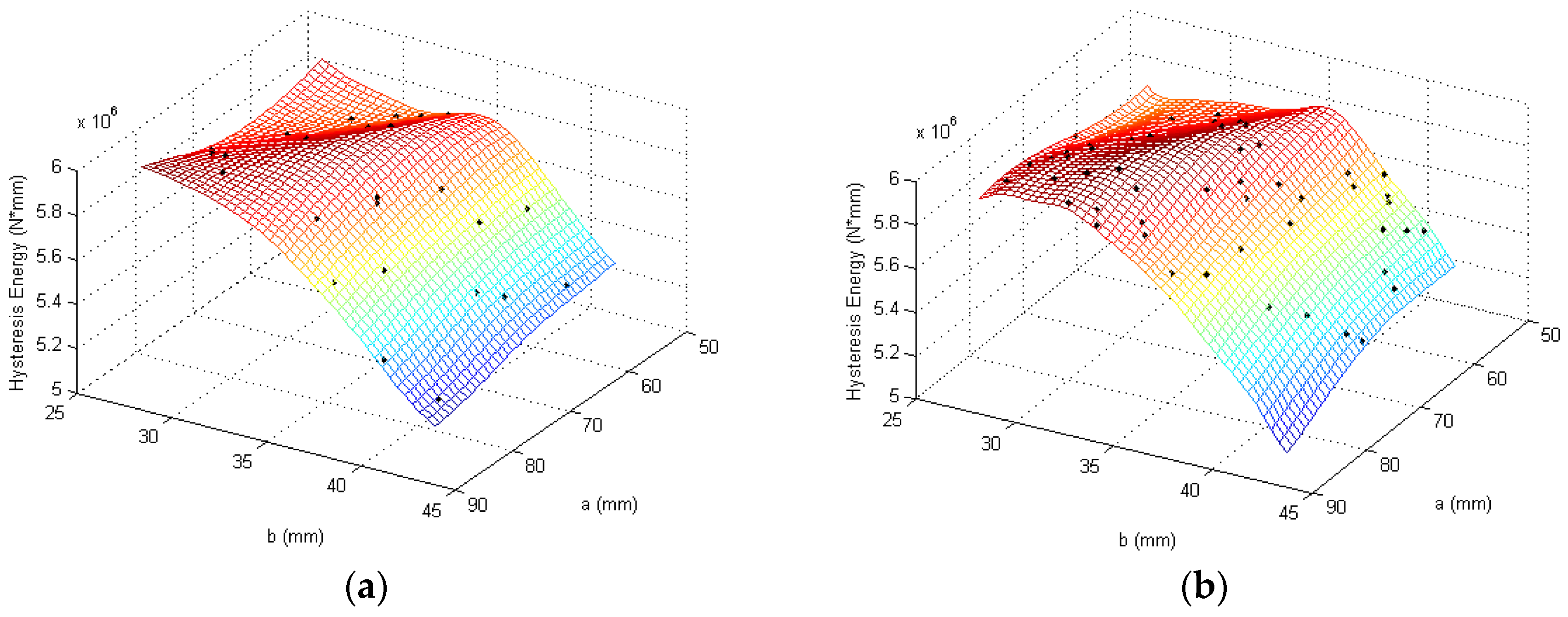
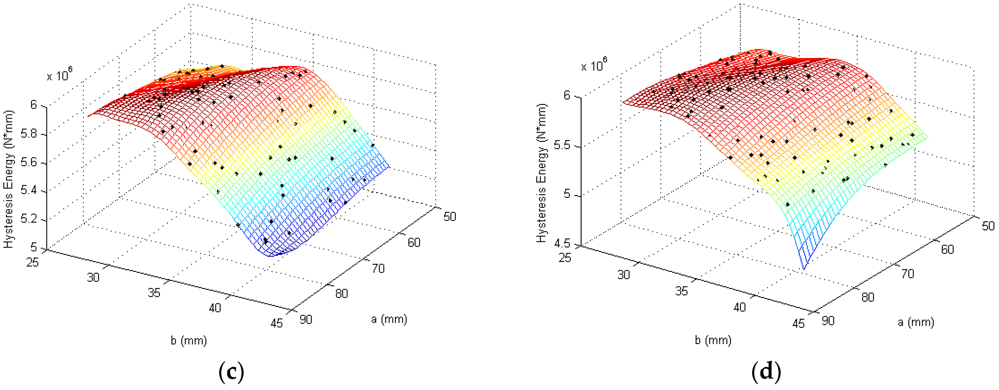
3.3. Design Parameters and Hysteretic Energy Dissipation Relationship

The thickness of all kinds of metal dampers changes when independent variables change on the response surface. It can be seen that hysteresis energy decreases along with the bounds of the independent variables in the SP2, SP3, and SP4 cases, but the response surface for SP1 seems to be parabolic instead of a monotonic decay trend. The existing research results [16] also show that when the thicknesses of the four kinds of metal dampers are equal, the same pattern (above) can be seen.

4. Optimization of Pore Parameters Based on the Kriging Surrogate Model

4.1. Optimization Problem

The problem of choosing pore parameters of the metal dampers, in order to maximize hysteresis energy, arises:
Find   x 1   and   x 2
M a x ( Y ( x 1 , x 2 ) )
Subjected to Equations (1) and (2), also
l b 1 x 1 u b 1
l b 2 x 2 u b 2
in which Y is the hysteresis energy function of independent variables x 1 and x 2 , and lb and ub are the lower and upper bounds.
The current optimal design problems need to be solved using an optimization algorithm. Classical optimization algorithms, such as the simplex method, the steepest descent method, and the sequential quadratic programming method, are all determined by local information (e.g., derivatives), so they are effective in a depth search but cannot effectively conduct a breadth search. These methods cannot jump out of the local optimum for classical optimization algorithms.
The SCE algorithm was proposed by Duan [17] to solve for the continuity of watershed hydrological model parameter selection problems. It combines certain complex search methods and the biological evolution principle in nature, in which every generation can be divided into several complexes that evolve independently. After some evolution, a new compound will be created by means of random restructuring in order to ensure the quality of the whole group’s overall improvement.

4.2. Process of Pore Parameter Optimization Based on the Kriging Model

The Kriging model can not only predict responses using the new input parameters, but can also estimate optimal parameters satisfied with equality or inequality response constraints in both linear and nonlinear systems. When the original surrogate model is constructed, the quality of the model can be assessed according to the accuracy of the predictions:
S C = 1 j = 1 q [ y ^ j y j ] 2 j = 1 q [ y j y ˜ ] 2
where y ^ j and y j are the jth component of the response vector of the surrogate model and the true value calculated via FE analysis, respectively; y ˜ is the mean of all true values. Some scholars proposed to maximize the expected increasing (EI) add criteria [15], multiple-spot add criteria [18], experience semivariogram add criteria [19], etc. Here the EI sample adding criteria is used.

4.3. Maximizing the Expected Increasing (EI) Add Criteria

Maximizing the expected increase (EI) is considered as a forecast variance weighted method. In the design, the point x, prior to its response value calculated in response to the value of y(x), is also unknown, but the Kriging agent model is able to predict its mean value y ˜ and the variance sigma σ 2   ( x ) . If the response to this optimal design value is y k * , it would improve the point target response value to I   ( x )   =   y k *   y ( x ) for the minimization problem, which follows a normal distribution, so the probability density function is:
1 2 π σ ( x ) e x p [ ( y k * I ( x ) y ˜ ( x ) ) 2 2 σ 2 ( x ) ]
Additionally, the response to the value of the target’s increased expectations is:
E [ I ( x ) ] = I = 0 I = I { 1 2 π σ ( x ) e x p [ ( y k * I ( x ) y ˜ ( x ) ) 2 2 σ 2 ( x ) ] } d I
After integration:
E [ I ( x ) ] = σ ( x ) [ u Φ ( u ) + ϕ ( u ) ]
u = y k * y ˜ ( x ) σ ( x )
in which Φ and ϕ are the positive probability distribution function and the probability density function, respectively.
Equation (10) is the sum of the two terms. The first is the predictive value y ˜ of point x, multiplied by the probability of improving the current optimal response, which is the difference. A larger x will cause the predicted variance to be small, which means that it will find little predictive value and a more accurate prediction point. Forecasting the variance of the probability density function of the product, it is clear that when the predicted value is relatively large, the value is large, but the probability density function of a limited predictive value is not far from the current optimal response. In Equation (10) the probability distribution function and the probability density function play the role of a “penalty” when a point is smaller than the current optimum of the forecast variance, which is expected to be very small and close to 0 or to have a negative value.
In summary, maximizing the expected increase aims to find a point to make the predictive value smaller than the current optimal response.

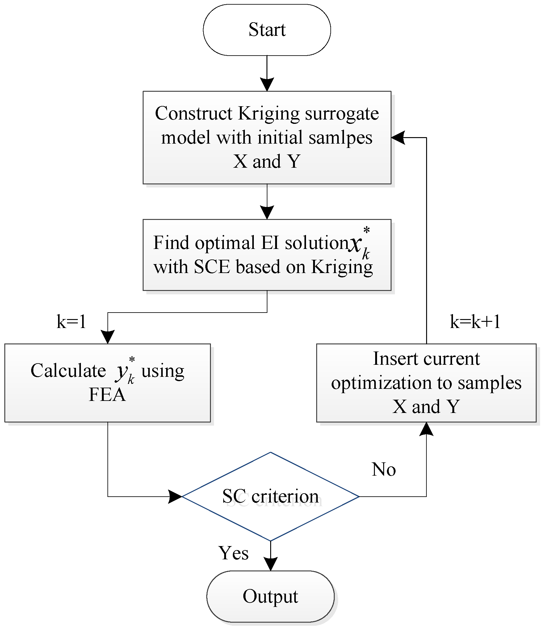
4.4. Optimization Process

The process of optimization based on the Kriging model can be described as follows (Figure 6):
  • Based on the initial sample points X and the response values Y, build agents for the Kriging model;
  • Use the SCE optimization algorithm to obtain the EI maximum;
  • Calculate the current optimal solution and its corresponding hysteresis energy, and set k = 1;
  • Run the convergence criterion test; if the convergence criteria meet the requirements, then the object problem optimal solution is acquired. If it is not satisfied, the value will be added to the sample of the current optimal design for the next optimization modeling until the convergence criteria is met.

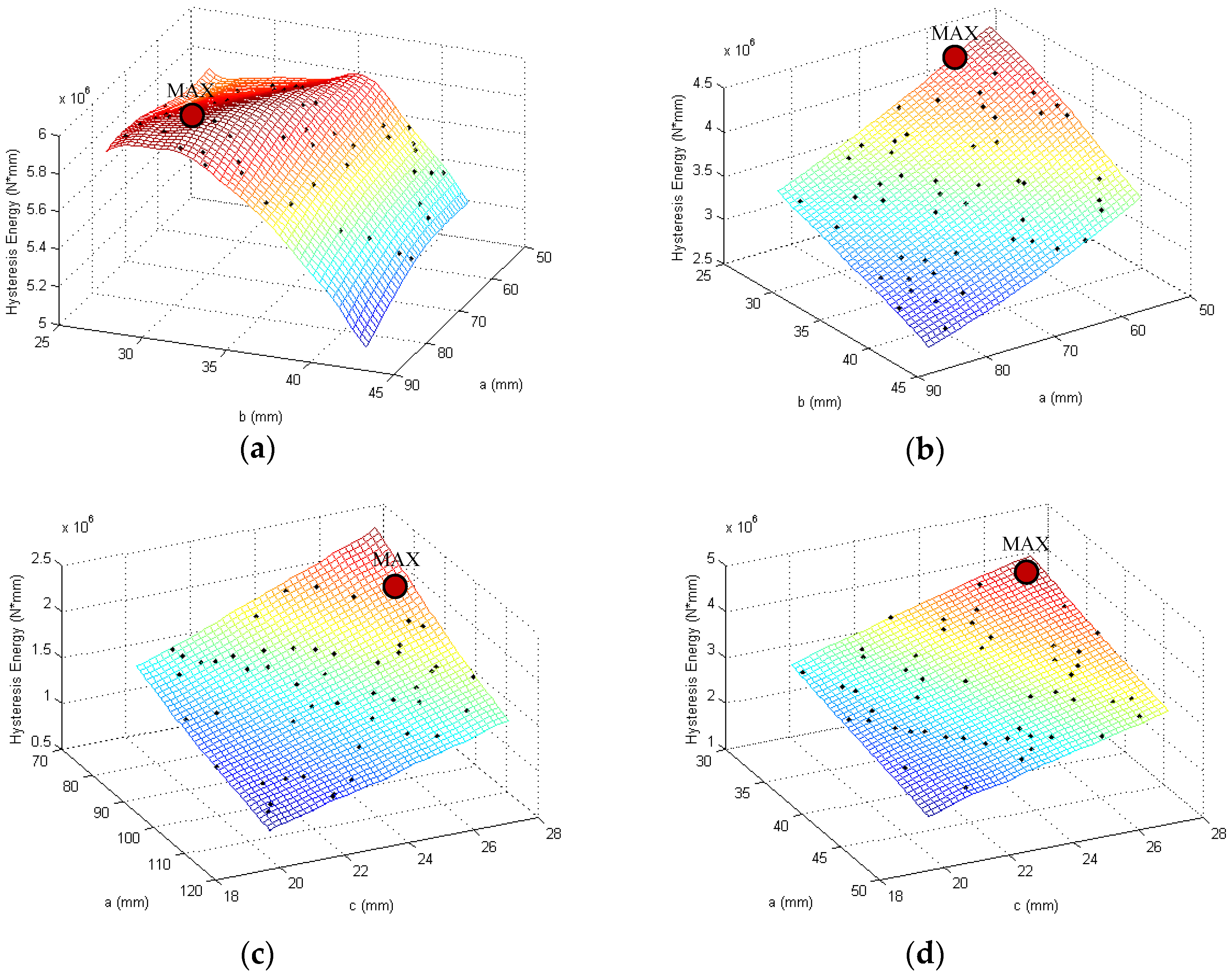
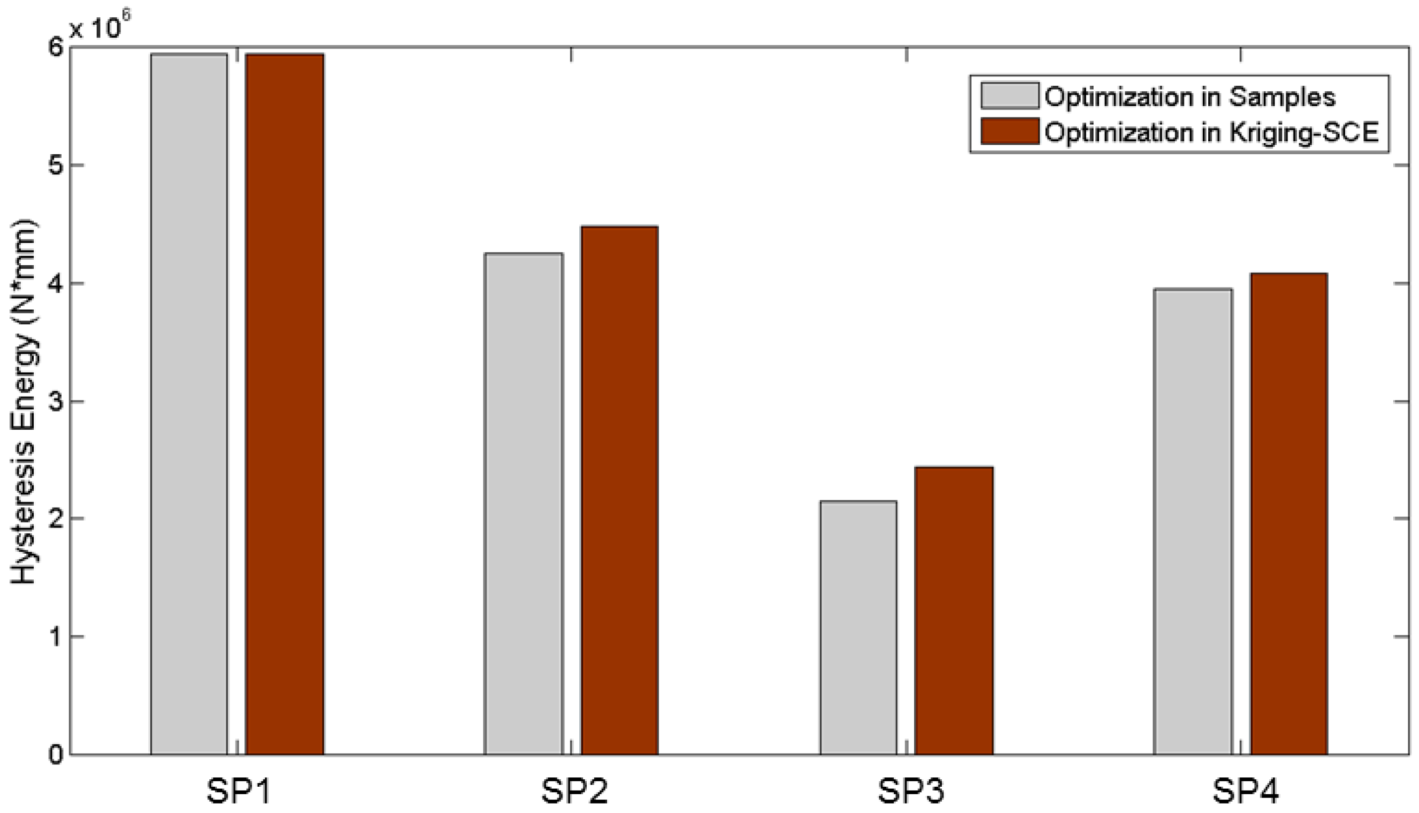
4.5. Optimal Design Results and Discussion

The optimization results of the dampers, based on four different opening shapes, are shown in Table 1. As shown in the table, maximum hysteresis energy exists in the feasible region for SP1, while the other dampers are shown in the feasible region boundary under the conditions of having the same amount of material and the same length and width in the plane. The result shows that thickness has very little influence on the hysteresis energy for these three types of plates, besides SP1. This table also shows that the larger the hysteresis energy with a smaller opening area is, there is a restriction relationship between the parameters of SP1 and the thickness of the steel plate. The hysteresis energy for the four kinds of coupling beam metal dampers, after optimization, is compared in Figure 7, which shows that SP1 has the maximum hysteresis energy while SP3 has the minimum capacity of hysteresis energy.
SP1 is selected to analyze the influence of the numbers of the initial samples on the optimization design efficiency. Four different initial samples (25, 50, 75, 100) were chosen to build the initial Kriging surrogate model, as shown in Figure 8. The shapes and types of all four different initial surrogate models were almost the same except for some minor local differences.
In order to illustrate the optimization design efficiency of the Kriging surrogate model, SP1 was optimized with the SCE optimization design. The calculation times for the different initial samples were compared using the same computer (Intel Core(™)[email protected] GHz, 16 G RAM, Santa Clara, CA, USA), as shown in Figure 9. The combination of the Kriging surrogate model with the SCE optimization algorithm could highly improve the parameter optimization design efficiency. Meanwhile, the initial sample had an influence on the design optimization efficiency. In general, as the initial samples increased, the surrogate model became more accurate and needed fewer iteration steps. However, the iteration steps of the SCE optimization algorithm may increase due to randomness during the period of searching for the optimum, as well as in the selection of a threshold at the end of the iteration. The dimensions of the optimal problem and the complexity of the engineering conditions, as well as the method of selecting initial samples, could influence the iteration numbers, as well as the calculation time. It should be noted that it also took time to calculate the hysteresis energy and it took longer to calculate the energy when the initial sample was increased. Thus, a larger initial sample is not better for the optimal design case.

5. Conclusions

In this paper, we studied four different coupling shear wall dampers with varying opening shapes and compared them for energy dissipation performance. By establishing the relationships between the opening size parameters and hysteresis energy based on the Kriging surrogate model, we optimized the parameters to allow the beam damper to achieve the maximum hysteresis energy. Two appealing conclusions could be reached as follows:
(1)
The maximum hysteresis energy exists in the feasible region for the plate with split elliptic pores, SP1, while the hysteresis energy is a monotone function in the feasible region. This suggests that the maximum hysteresis energy lies at the boundary of the feasible region for the plate with one central elliptic pore, and the ones with uniform row pores and uniform column-row pores.
(2)
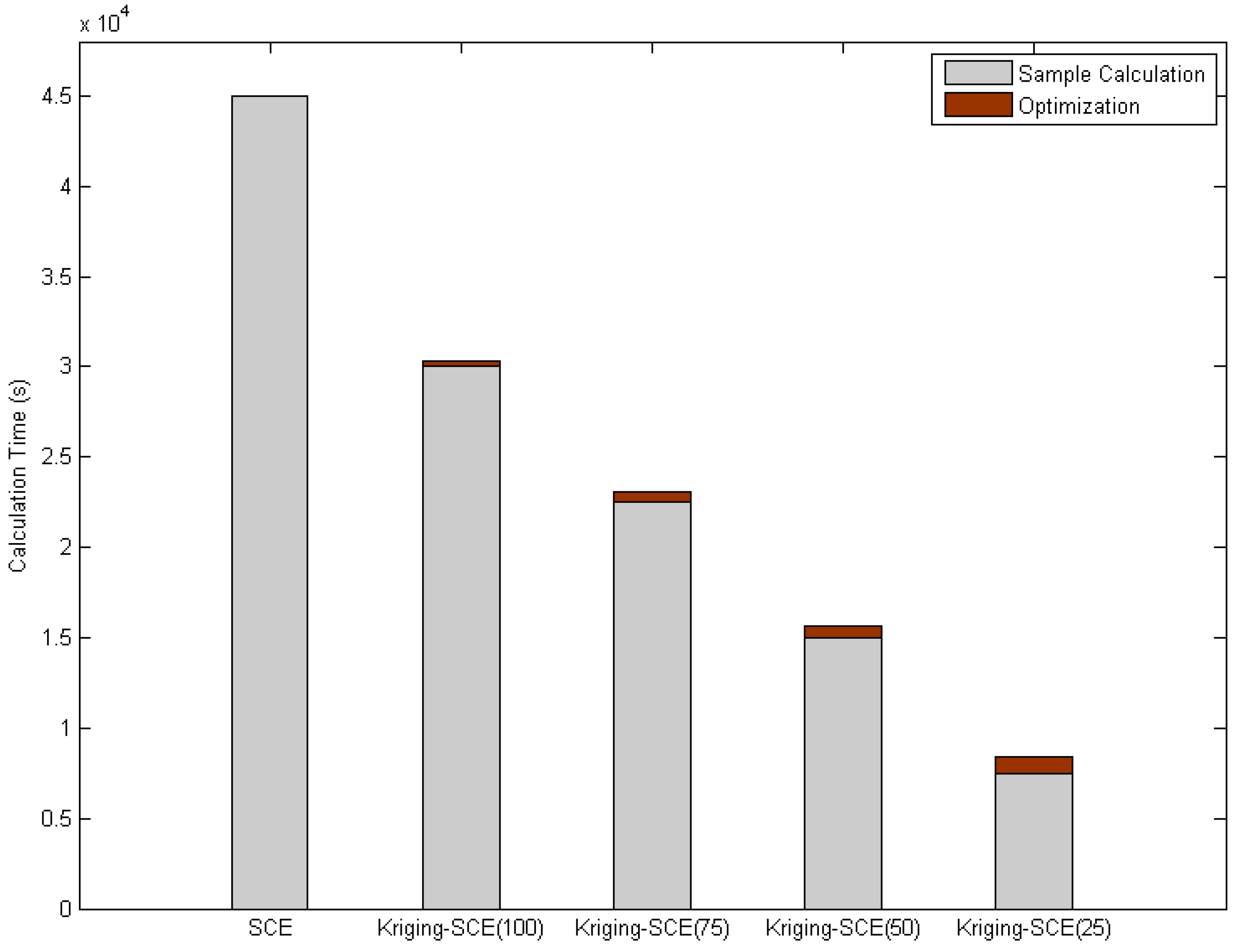
The parameter of the optimum design method, based on the combination of the Kriging surrogate model with an intelligence algorithm, could significantly reduce the calculation time. Additionally, the initial sample conditions do influence the speed of the iterations.
The designed coupling shear beam dampers with split elliptic pores, SP1, have many advantages, which include a high hysteresis energy dissipation performance, facile fabrication, and low costs. We believe the optimal SP1 opening shape we found in this work will have a promising future in manufacturing and applications.

Acknowledgments

This work is supported by the National Natural Science Foundation of China (NSFC91315301-12).

Author Contributions

Jinping Ou and Dongsheng Li conceived the idea and provided the support of the experimental setup, Zhe Zhang designed the experiments and analyzed the data, Zhe Zhang and Shuaifang Zhang performed the experiments, Dongsheng Li and Zhe Zhang wrote the paper, Shuaifang Zhang helped to modify the grammar in this paper.

Conflicts of Interest

The authors declare no conflicts of interests.

References

  1. Paulay, T. Simulated Seismic Loading of Spandrel Beams. J. Struct. Div. ASCE 1971, 97, 2047–2419. [Google Scholar]
  2. Choo, B.S.; Coull, A. Stiffening of Laterally Loaded Coupled shear Walls on Elastic Foundations. Build. Environ. 1984, 4, 251–256. [Google Scholar] [CrossRef]
  3. Kelly, J.M.; Skinner, R.I.; Heine, A.J. Mechanisms of Energy Absorption in Special Devices for Use in Earthquake Resistant Structures. Bull. Environ. Contam. Toxicol. 1972, 5, 63–73. [Google Scholar]
  4. Skinner, R.I.; Tyler, R.G.; Heine, A.J. Hysteretic Dampers for Earthquake-Resistant Structures. Earthq. Eng. Struct. Dyn. 1975, 3, 287–296. [Google Scholar] [CrossRef]
  5. Fortney, P.J.; Shahrooz, B.M.; Rassati, G.A. Large-Scale Testing of a Replaceable “Fuse” Steel Coupling Beam. J. Struct. Eng. 2007, 133, 1801–1807. [Google Scholar] [CrossRef]
  6. Rassati, G.A.; Fortney, P.J.; Shahrooz, B.M.; Johnson, P.W., III. Performance Evaluation of Innovative Hybrid Coupled Core Wall Systems. In Composite Construction in Steel and Concrete VI; American Society of Civil Engineers: Reston, VA, USA, 2011; pp. 479–492. [Google Scholar]
  7. Fortney, P.J.; Shahrooz, B.M.; Rassati, G.A. The Next Generation of Coupling Beams. In Proceedings of the Fifth International Conference on Composite Construction in Steel and Concrete, Mpumalanga, South Africa, 18–23 July 2004; pp. 619–630.
  8. Chung, H.S.; Moon, B.W.; Lee, S.K.; Park, J.H.; Min, K.W. Seismic performance of friction dampers using flexure of RC shear wall system. Struct. Des. Tall Spec. Build. 2009, 18, 807–822. [Google Scholar] [CrossRef]
  9. Kim, H.J.; Choi, K.S.; Oh, S.H.; Kang, C.H. Comparative study on seismic performance of conventional RC coupling beams and hybrid energy dissipative coupling beams used for RC shear walls. In Proceedings of the 15th World Conference on Earthquake Engineering, Lisbon, Portugal, 24–28 September 2012.
  10. Choi, K.Y.; Kim, H.J.; Kang, C.H. Experimental validation on dynamic response of RC shear wall systems coupled with hybrid energy dissipative devices. In Proceedings of the 15th World Conference on Earthquake Engineering, Lisbon, Portugal, 24–28 September 2012.
  11. Lyons, R.M.; Montgomery, M.S. Enhancing the seismic performance of RC coupled wall high-rise buildings with visco elastic coupling dampers. In Proceedings of the 15th World Conference on Earthquake Engineering, Lisbon, Portugal, 24–28 September 2012.
  12. Mao, C.; Dong, J.; Li, H.; Ou, J. Seismic performance of RC shear wall structure with novel shape memory alloy dampers in coupling beams. In Proceedings of the Society of Photo-Optical Instrumentation Engineers (SPIE) Conference Series, San Diego, CA, USA, 11 March 2012; pp. 304–320.
  13. Simpson, T. W.; Lin, D.K.; Wei, C. Sampling Strategies for Computer Experiments: Design and Analysis. Int. J. Reliab. Saf. 2001, 2, 209–240. [Google Scholar]
  14. Lee, K.H.; Park, G.J. A global robust optimization using the Kriging based Approximation model. JSME Int. J. 2006, 49, 779–788. [Google Scholar] [CrossRef]
  15. Gao, Y.; Wang, X. Surrogate-based process optimization for reducing warpage in injection molding. J. Mater. Process. Technol. 2009, 209, 1302–1309. [Google Scholar] [CrossRef]
  16. Zhang, Z.; Ou, J.; He, Z. Optimization Design for Coupling Beam Dampers of Shear Walls. Appl. Mech. Mater. 2013, 444, 115–121. [Google Scholar] [CrossRef]
  17. Duan, Q.; Sorooshian, S.; Gupta, V. Effective and efficient global optimization for conceptual rainfall-runoff models. Water Resour. Res. 1992, 28, 1015–1031. [Google Scholar] [CrossRef]
  18. Sakata, S.; Ashida, F.; Zako, M. An efficient algorithm for Kriging approximation and optimization with large-scale sampling data. Comput. Methods Appl. Mech. Eng. 2004, 193, 385–404. [Google Scholar] [CrossRef]
  19. Song, X.M.; Xia, J. Integration of a statistical emulator approach with the SCE-UA method for parameter optimization of a hydrological model. Chin. Sci. Bull. 2012, 57, 3397–3403. [Google Scholar] [CrossRef]
Figure 1. Section dimensions of the components: (a) Plate with split elliptic pores (SP1); (b) Plate with one central elliptic pore (SP2); (c) Plate with single column of uniform pores (SP3); (d) Plate with two columns of uniform pores (SP4).
Applsci 07 00137 g001
Figure 2. Curve of constitutive relation.
Applsci 07 00137 g002
Figure 3. Load–displacement curve.
Applsci 07 00137 g003
Figure 4. Parameter sampling for coupling beam metal dampers: (a) SP1; (b) SP2; (c) SP3; and (d) SP4.
Applsci 07 00137 g004aApplsci 07 00137 g004b
Figure 5. The Kriging model for four kinds of coupling beam metal dampers: (a) SP1; (b) SP2; (c) SP3; and (d) SP4.
Applsci 07 00137 g005
Figure 6. Optimization process.
Applsci 07 00137 g006
Figure 7. Hysteresis energy of four kinds of optimized coupling beam metal dampers.
Applsci 07 00137 g007
Figure 8. Kriging models with different initial samples for SP1: (a) 25 samples; (b) 50 samples; (c) 75 samples; and (d) 100 samples.
Applsci 07 00137 g008aApplsci 07 00137 g008b
Figure 9. Calculation times.
Applsci 07 00137 g009
Table 1. Optimization results for sample optimal solution (SOS) and optimization model solution (OMS).
Opening ShapesDesign Variablesx1 (mm)x2 (mm)Hysteresis Energy (N*mm)Hysteresis Energy Improvement
SP1SOS76, 7231, 645,940,7770.064%
OMS74, 7431, 785,944,571
SP2SOS58, 6026, 834,252,9115.3%
OMS53, 4226, 714,477,092
SP3SOS84, 6627, 032,141,27713.7%
OMS74, 6727, 272,436,392
SP4SOS32, 0426, 93,950,7006%
OMS30, 6827, 274,084,100

