1. Introduction
A router with an optical data plane is needed to support high-bandwidth communication on the Internet. Optical packet switching can support the Internet’s multiplexing efficiency and flexibility, while avoiding costly and complex conversion from optical formats required for high-bandwidth, long-distance transmission. It differs from circuit switching, which can already be accomplished optically with micro-mirrors, wavelength selection, or electro-optical switches, but which is effective only for traffic that has very long and predictable patterns. An Internet router is the most common form of packet switch used for long-distance communication, and its operation can be reduced to four core functions—hop count decrement, header lookup, checksum calculation, and packet traffic merging. This paper presents our experience implementing or simulating each function as optical processing of packets and the potential for future integration to a complete optical packet switching device, based on the existing requirements of Internet routers. Our goal is to determine the implications of an all-optical solution on emerging approaches to digital optical processing. An earlier version of this work was presented as an invited paper at SPIE Photonics West [
1], updated herein with additional history (
Section 1.2), significant clarifications (especially to
Section 5 and
Section 6), a detailed discussion of the implications of our assumptions (in
Section 1.3 and
Section 8), and details on recent related work on processing-compatible all-optical phase regeneration (
Section 8).
1.1. The Need for Optical Routing
A high-bandwidth Internet requires per-packet channel sharing and optical transmission. Optical circuit switching is already widely used but limited to traffic that is predictable over long timescales and can be very inefficient for typical Internet traffic. High-efficiency capacity sharing requires packet-level processing. Packets are variable-length messages and packet-level statistical multiplexing results in an effective capacity gain of 3–10 times larger, i.e., a 10 Gb/s link shared using packet multiplexing can support tens to hundreds of users with 1 Gb/s data flows, because Internet traffic is bursty and packet-based sharing is efficient. This efficiency occurs when multiplexing at the packet level and is undermined by multiplexing where shares are allocated longer timescales, e.g., for packet bursts or persistent channels.
High-bandwidth, long-distance data transmission necessarily requires optical signals. Electronic transmission is limited to roughly 10 Gb/s over 10 m. Electronic signals must be slowed down to traverse longer distances, or can conversely support higher rates over shorter distances. Optical transmission is required for higher bandwidth and distance combinations and is typical for long-haul Internet connections in the network core. As transmission bandwidths increase, the use of optics is expanding from the core to metropolitan aggregation sites and ultimately to end users.
An Internet router is a device with multiple inputs and outputs that shares channel capacity on a per-packet basis [
2]. Assuming its inputs and outputs are already often optical, having an optical router would avoid complex and costly optical-electronic-optical (OEO) conversion. Routers are composed of a control plane and a data plane; the control plane exchanges information with other routers to ensure that packets make progress toward their destination and the data plane is a packet switch that directs incoming packets as indicated by their header information and control plane configuration (a process known as ‘forwarding’ when it applies to Internet protocol (IP) datagrams). In this paper, we focus on developing an optical data plane to natively switch optically encoded packets and we assume a conventional electronic control plane for management operations.
1.2. Some History
The Internet is the most recent stage of an evolution in communication architecture that began with telephony over 120 years ago. Early telephone network architectures used circuits, a dedicated physical path between endpoints. The need for more flexible channel sharing led to the development of virtual circuits, in which a circuit is emulated by dedicating fractions of resources (frequencies/wavelengths, time slots, or combinations) over multiple paths. Transmissions are multiplexed over these resource components to emulate a channel with a fixed capacity.
Most communication, whether data exchanges, audio, or even compressed video, are more typically bursty and do not require fixed capacity. In this case, concurrent channels can share each other’s spare capacity during idle periods. This is the basis of packet switching, which is a dynamic, adaptive, on-demand variant of time-division multiplexing. Unlike a circuit, a packet network reacts to each message that traverses it, but this was difficult to accomplish at high bandwidths in the early Internet (1970s–1990s).
In the mid-1990s, the Internet’s increasing need for the flexibility and more efficient channel sharing of packet switching led to the development of Tag Switching [
3] (also known as Flow Switching [
4] and more recently as Multiprotocol Label Switching, MPLS [
5]). Groups of packets are relayed through a predetermined set of switches using configurations that are deployed in advance, making decisions only once for each group. These mechanisms allowed networks to leverage some of the efficiency of on-demand resource sharing while reducing the processing needed for each message, but also limited sharing to timescales of the packet bursts.
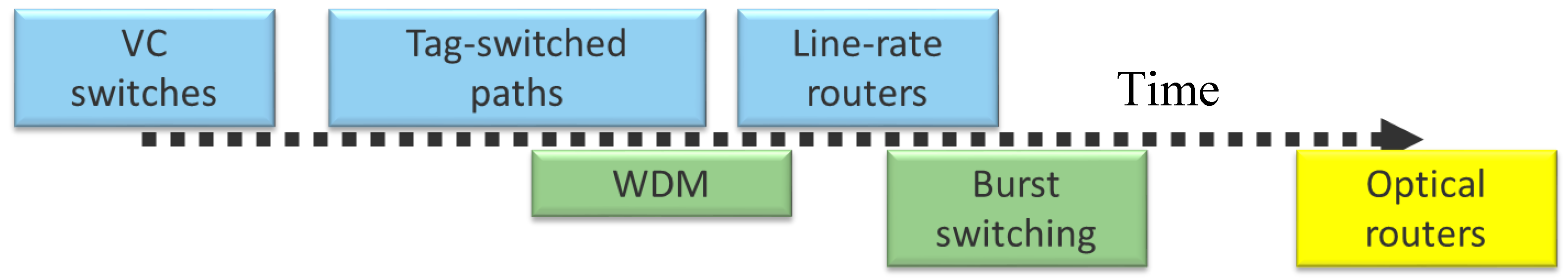
The final step in the evolution towards increasingly shorter channel multiplexing timescales culminated in the development of electronic packet switching that was capable of relaying packets at full electronic transmission rates (so-called ‘line-rate routers’), which occurred towards the turn of the last century. This native electronic packet switching performs on-demand resource sharing for each packet, and is the basis of electronic Internet routers. This evolution is shown in the top of
Figure 1.
Optics is currently recapitulating this evolution (bottom of
Figure 1). It began with dedicated light paths and evolved to virtual light paths using multiplexing wavelengths (WDM), with wavelength conversion to avoid the need for global coordination of wavelength assignment. Optical WDM thus corresponds roughly to electronic virtual circuits. Optical Burst Switching [
6] (another variant is known as Terabit Burst Switching [
7]) is the optical corollary of Tag Switching, configuring paths for small groups of adjacent packets with the same destination, effectively providing very short timescale circuits, corresponding to electronic tag switching. The corollary of electronic line-rate packet switching is all-optical packet switching, and is the obvious conclusion of this evolution. An optical router assigns resources for each message, which results in much more efficient resource sharing and this sharing efficiency is why we focus on a packet switched approach.
The alternative to optical packet switching would be to optimize the network to support less dynamic, adaptive, and efficient sharing. This is only possible if data exchange patterns are both known in advance and are stable over long periods. Such patterns currently occur in datacenters and other researchers are developing optical circuit systems for that environment [
8]. We prefer to focus on the more general, most flexible solution of optical packet switching, which would support not only these known, long-scale traffic patterns but also the unknown, rapidly shifting patterns prominent elsewhere throughout the Internet.
1.3. Our Assumptions
We focus on the Internet router as the device that shares capacity between interconnected optical links. As a result, we assume optical links that do not include dimensions that introduce their own, distinct sharing mechanism—i.e., they are individual, directional channels with no further partitioning by wavelength, phase, polarization, etc. As with electronic Internet channels, we assume that these dimensions may be used to encode information, e.g., symbols that represent multiple bits, but that they are not otherwise used to partition packets within a link.
Similarly, we assume point-to-point (i.e., unicast) links. Shared links require a media sharing arbitration mechanism, often known as a Medium Access Control (MAC) protocol; this arbitration is more efficient when coordinated explicitly by the multiplexing mechanism inside a packet switch, which is why Ethernet evolved from shared, MAC-controlled links to dedicated unicast links between packet switches.
We also avoid assumptions on the size of packets, other than that they conform to Internet requirements. IPv4 packets (also called ‘datagrams’) are a minimum of 20 bytes, but typically exhibit a bimodal distribution of 40 and around 1500 bytes [
9]. IPv6 packets (these too are called ‘datagrams’) are a minimum of 40 bytes and typically exhibit a bimodal distribution at 60 and around 1500 bytes [
10]. Packets on a link are assumed to have bytes in the order specified in the IPv4 or IPv6 formats—header bytes arrive in the order that they are defined in the IP standards. We also do not assume adjacent (or nearly-adjacent) packet sequences with the same destination, i.e., we do not assume typical flow or burst sequences of packets. We want a solution that works in the absence of such flow properties, without advance configuration.
This paper focuses on whether implementing an Internet router as an all-optical device is feasible by focusing on its four defining capabilities—hop count decrement, header lookup (for packet demultiplexing by Internet routing rules), checksum update, and packet traffic merging (multiplexing and output port contention). This approach is intended to support rates far beyond those possible with electronics, but is not expected to reduce either power or cost. Although we do not assume the need for new materials, our approach requires integration of active and passive optical devices on a single substrate, as noted in
Section 8.
Finally, we assume an optical encoding compatible with optical processing because conversion between transmission and processing encodings is as complex and costly when both are optical as when converting from optical to electrical, and we want to avoid that cost and complexity. Our preliminary implementations utilize binary encodings (e.g., on-off keying, return-to-zero (RZ) encoding, or binary phase-shift keying (BPSK)); in
Section 7, we address extending these designs to higher-density, multiple bit symbol encodings (e.g., M-PSK, , where “M” refers to an integer, as in “8-PSK” or “16-PSK") for more efficient long-distance transmission.
2. Internet Router Architecture
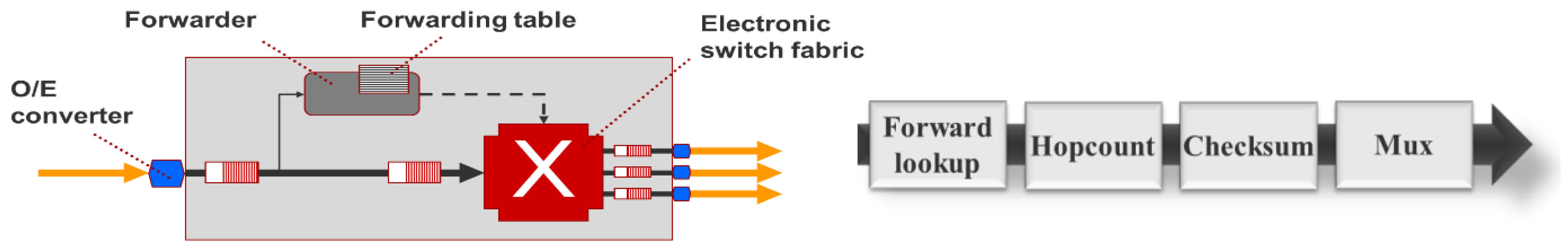
Internet routers typically use an electronic data plane, even when interfaced to optical links. They switch incoming packets towards their destination, a process known as “forwarding” when it refers to Internet packets (datagrams), as shown in
Figure 2 (left). A forwarding engine (or ‘forwarder’) examines the packet header, matching it to entries in a forwarding table. This table is determined manually by the operator or by exchanges with the control planes of adjacent routers. The packet passes through a switching fabric, taking the path based on the result of this lookup. At various locations in this process, packets may be queued to avoid backlogs due to slow header processing, switch fabric availability, output port contention (competition), or to adapt between internal transfer rates and incoming and outgoing line data rates.
Although Internet routers may include a number of additional capabilities, such as filtering and proxying (relaying) high level protocols, the core operation of a router is composed of these four independent functions in sequence: forwarding lookup, hop count decrement, checksum computation, and packet multiplexing (
Figure 2, right) [
11].
Packet forwarding lookup, sometimes called ‘header lookup’, matches the header destination address to an internal forwarding table, whose entries are patterns. IP datagrams are matched in this table using “longest prefix” matching. Forwarding entry patterns consist of a sequence of consecutive zeroes and ones, followed by “don’t cares” (indicated as ‘x’), sometimes indicated with the “don’t cares” as zeroes followed by a “mask length” indicating the number of non-don’t care bits (e.g., 11xxxxxx is denoted as 11000000/2). All matches start at the high-order bit and proceed to lower-order bits. Longer matches take precedence over shorter matches, e.g., a packet destined for address 11010111 that matches both 11000000/2 (i.e., 11xxxxxx) and 11010000/4 (i.e., 1101xxxx) would select the latter. IPv4 addresses are 32 bits long, but, typically, patterns are no longer than 24 bits inside the network (vs. at the user edge); IPv6 addresses are 128 bits long, but typically patterns are 64 bits or less. Routers in the core of the Internet can have several hundred thousand distinct patterns and packets not matching any patterns are silently dropped.
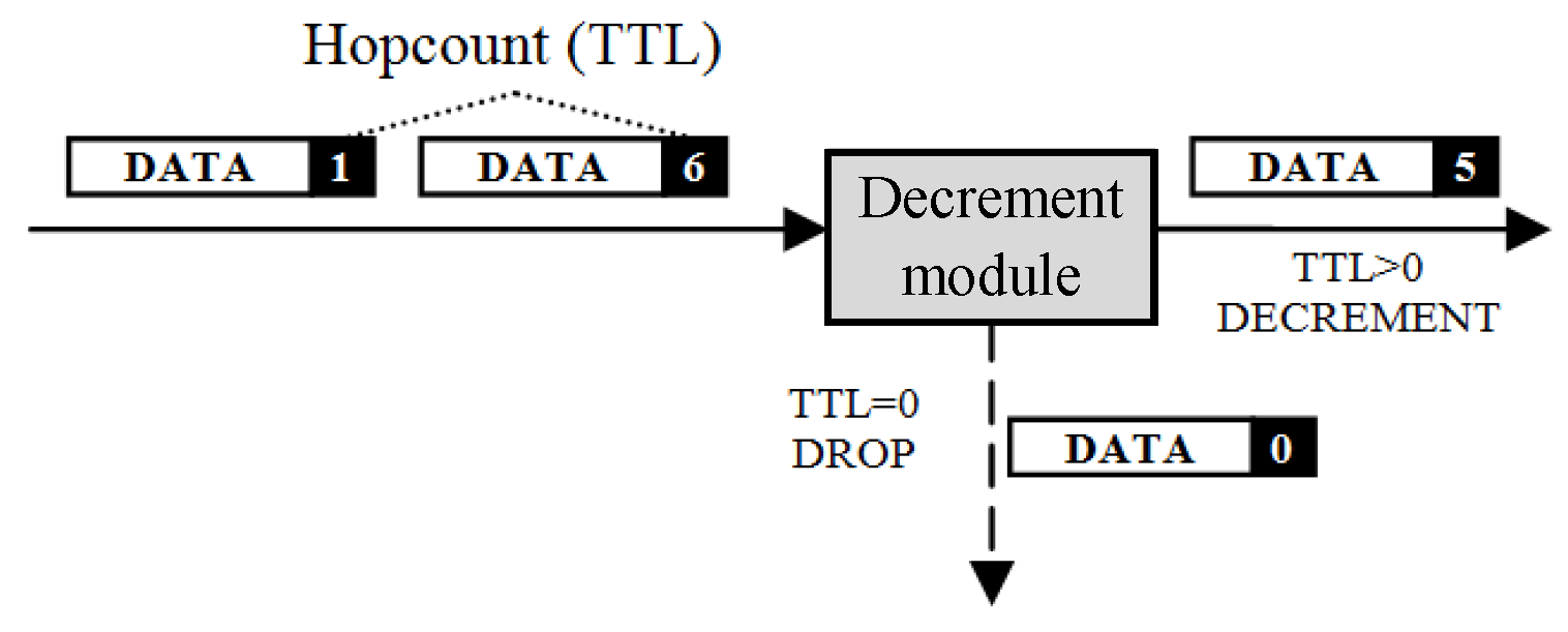
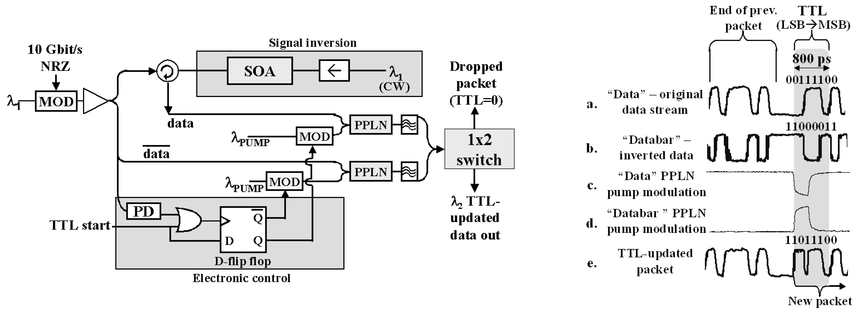
The hop count is a field in the header of Internet packets. In IPv4, it is called “Time-to-Live” (TTL), which originally indicated the number of seconds a packet was allowed to persist in the network. In IPv6, the field has been renamed “Hop Limit” to more accurately reflect what it tracks—the maximum number of routers traversed (in IPv4, every router is required to decrement the TTL by at least one even when a packet takes less than one second to forward). In both cases, the hop count field is decremented by at least one (typically exactly one) at every router; when the count reaches zero, the packet is discarded. The hop count field avoids the potential for packets to accumulate and thus disable a network; an ‘immortal’ packet that is misrouted in a loop might interfere with new packets entering. By ensuring that all packets ‘die’ after some finite time, Internet architects protect the network from transient routing loops and ensure that any network can be cleaned of ‘zombie’ packets by shutting down network inputs, rather than requiring the entire network to be disconnected and/or rebooted. Although it may seem wasteful to lookup a packet that might be then dropped because its hop count is exceeded, it is more likely that a packet would be dropped because of a forwarding lookup failure, so this step often happens second in the sequence. In addition, a packet might be destined to the router itself (e.g., to its control plane), in which case the hop count would not be decremented because the packet does not strictly traverse the router; this decision cannot be made until after the forwarding step.
IPv4 packets include a checksum that validates the correctness of the header [
9]. The IP checksum is validated and recomputed at each hop using the Internet checksum algorithm—it is a 16-bit, one’s complement sum of the data in the header [
12]. This checksum is also used to validate the entire contents of packets at other protocol layers, notably TCP (the Transmission Control Protocol) and UDP (the User Datagram Protocol). The one’s complement sum is the same as a two’s complement sum whose carry-out (from the high-order bit) is wrapped around as the carry-in to the low-order bit. The IP checksum changes whenever any field of the packet header changes, e.g., when the hop count (TTL) field is decremented by forwarding at a router. IPv6 does not include a separate header checksum; it assumes that the IP header is sufficiently protected by checksums at other layers (e.g., link) [
10]. Again, although it may seem wasteful to do forwarding lookup and hop count decrement on a packet whose checksum is invalid, such cases are sufficiently rare that it is effective to process the unmodified header (to validate the checksum) and modified header (to recompute the new checksum) at the same time as checksum validation.
Finally, a router needs to deal with output port contention, when two packets seek the same output port at the same time. This is a multiplexing function, needed to manage sharing of the output resources. It necessarily requires either delaying (preferably) or discarding some of the packets competing for the same resource. The fewer discarded packets, the higher the efficiency of the multiplexing function.
Each of these functions can be challenging to convert to optical processing in different ways. Forwarding lookup is difficult because of the length of the patterns and the number of concurrent patterns being matched. Hop count decrement and Internet checksum validation and recomputation are both difficult because they require mathematical digital optical processing. Multiplexing is difficult because it requires delaying packets and light can be difficult to delay. However, for each of these challenges, we have developed a candidate approach that has been validated either by experimentation or simulation and is presented in
Section 3,
Section 4,
Section 5 and
Section 6. A final challenge involves integrating these steps and composing them in sequence, which is addressed in the discussion of feasibility presented in
Section 7.
3. Optical Forwarding
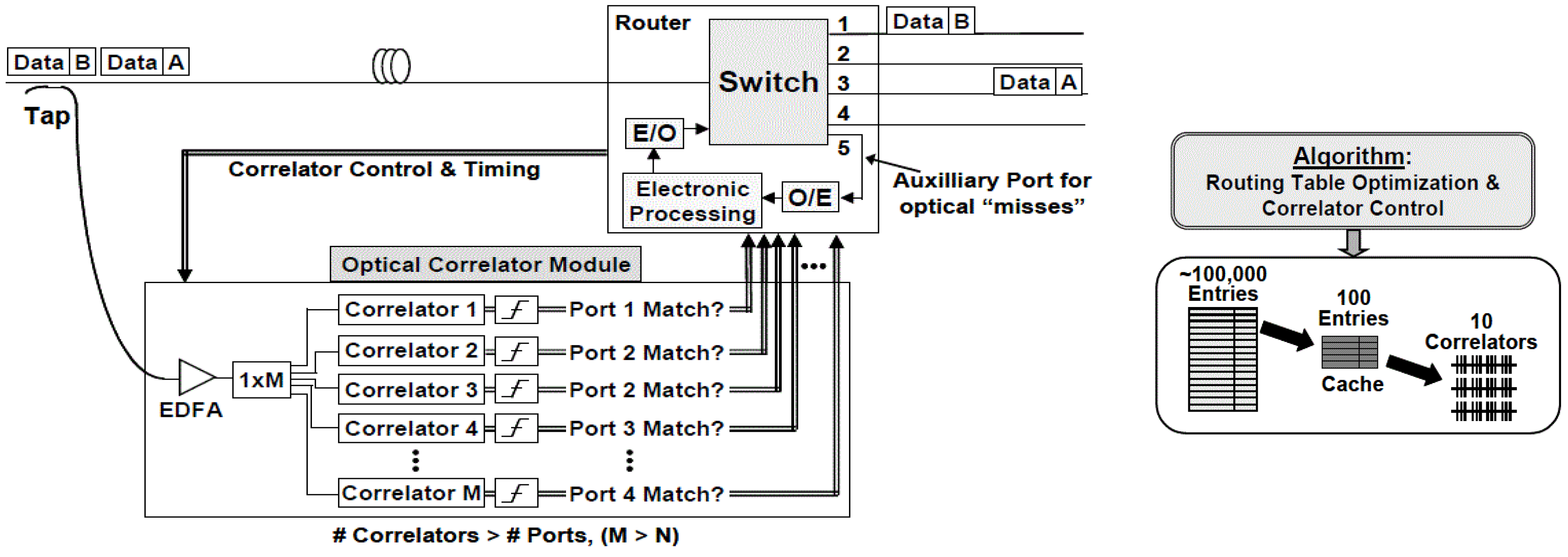
Optical packet forwarding requires performing a longest prefix match on a potentially very large number of forwarding table patterns, each of which could be 24–64 bits long. This process is sometimes simplified in modern routers, so that the forwarding table uses only fixed-length entries, replicating entries where necessary to represent shorter patterns. As a result, longest-prefix matching can be implemented as fixed-length pattern match, which itself can be implemented optically by a set of correlators (
Figure 3, left) [
13]. The number and length of the correlators can be managed by compressing the forwarding table to represent the most frequently used entries, in which several hundred thousand entries often can be sufficiently represented by approximately 100 entries (
Figure 3, right) [
14].
Forwarding table entries indicate the egress port and next-hop link layer address for each matched destination address [
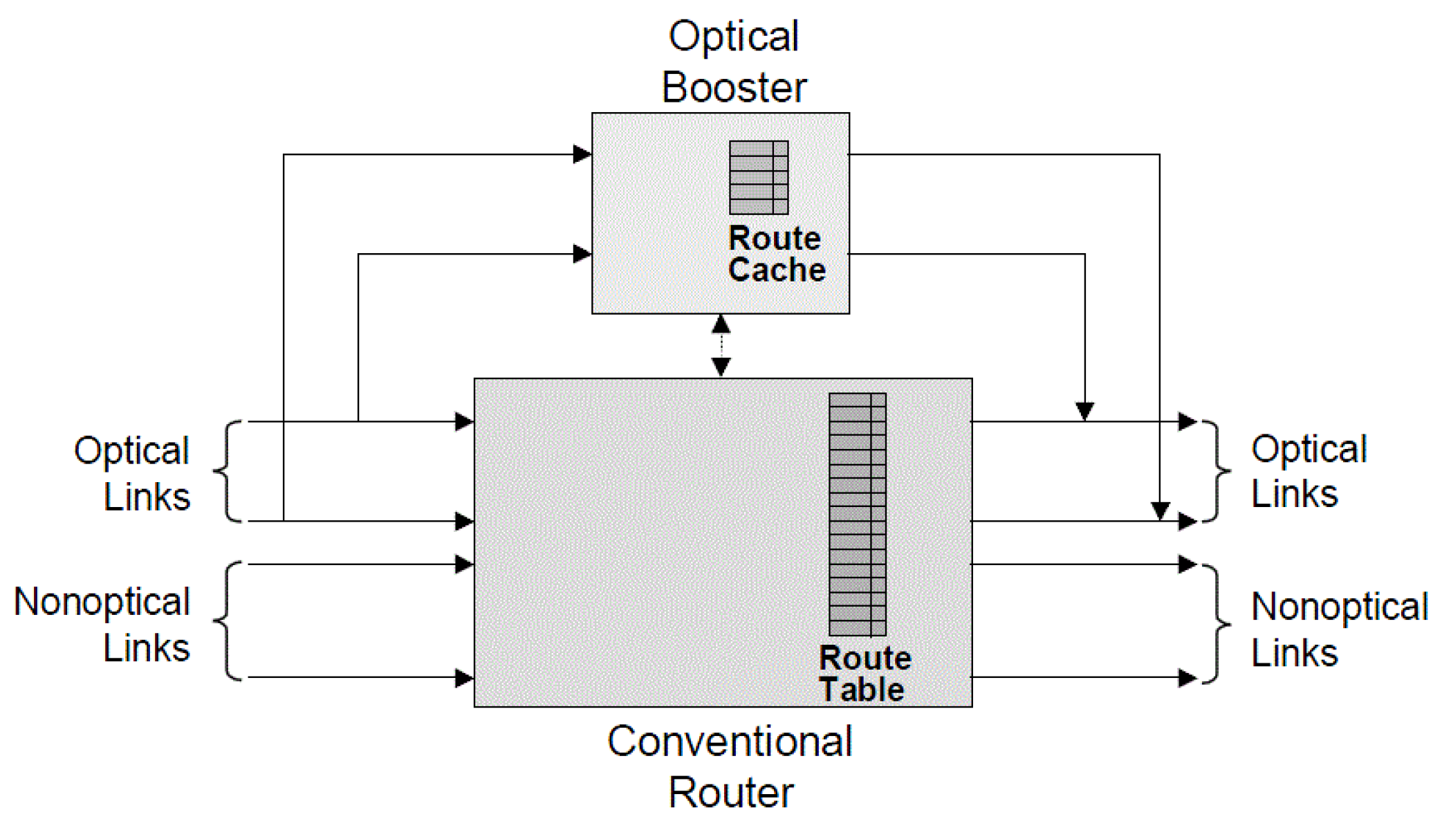
2]. For shared output links, the next-hop link address indicates which node on the output link is the intended recipient. For networks whose links are point-to-point, as we assume, the next-hop link layer address can be omitted, thus the resulting table can often be compressed by considering entries to the same egress port. Analysis of the table in this manner frequently yields a very small number of patterns (e.g., <10) of a very small number (e.g., 5–8) of 0/1 (non-don’t care) bits and this pattern might not start with the highest bit and its 0/1 values may not be adjacent, which differs from the original IP forwarding table patterns [
15,
16,
17]. This analysis may result in a set of patterns that may be more feasible to implement, using only a small set of correlators that each examine a small number of bits. Such a compressed table may not match 100% of incoming packets, but an optical router can be coupled with a conventional electronic router in parallel, the latter to handle packets not matching this small number of compressed optimized patterns (
Figure 4) [
18].
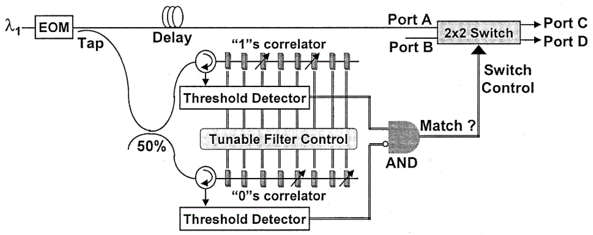
We implemented a configurable header correlator based on this approach and measured its performance using 10 Gb/s non-return-to-zero (NRZ) encoded packet headers (
Figure 5). The data rate was slower than desired due to the limitations of available lab equipment; given appropriate equipment, faster data rates can be simpler to implement due to the smaller size of the correlator device. Our correlators were able to match only “1” values in the NRZ encoded data, so we needed to match the “1” values and “0” values separately (don’t care values were ignored and not matched). The “1” values were matched against the incoming data, and the “0” values were matched against the complement of the incoming data. Threshold detectors combined the individual bit match signals to determine when the entire pattern matched, and then the correlator outputs were combined to control a 2 × 2 optical switch.
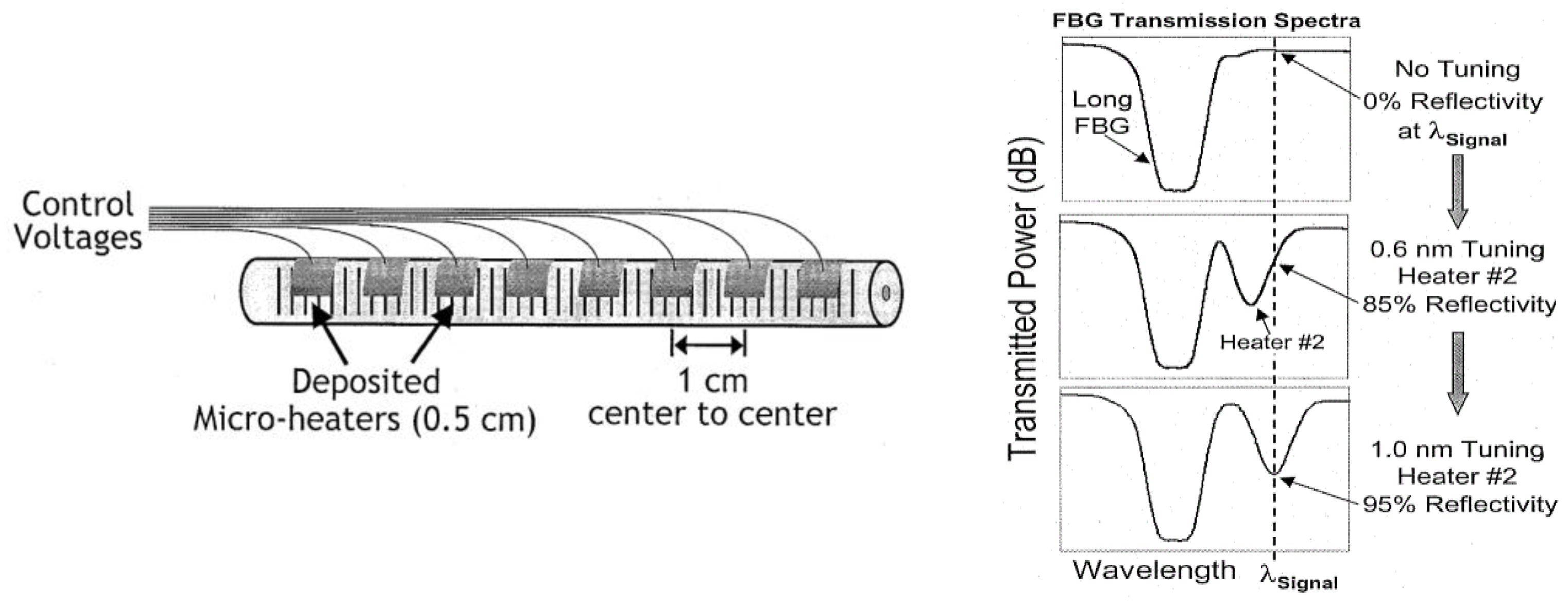
The correlators were implemented using 0.5 cm micro-heaters deposited on 1 cm centers on a Fiber Bragg grating (FBG) (
Figure 6, left), where the micro-heaters could be controlled to vary reflectivity
Figure 6, right). The correlators were tuned to match two different header patterns (1010 and 1000), and the system successfully switched headers based on their value (
Figure 7). Packet payloads would follow the same path as the header by latching the output of the correlator, either electronically or optically, until the beginning of the next packet. A delay in the data path allows the header match to be completed in time to configure the 2 × 2 switch to affect the corresponding packet header (
Figure 5).
5. Optical Checksum
Routers processing IPv4 packets are required to validate the IPv4 checksum field and to update its value to accommodate header field changes (e.g., hop count decrement). Although the shift to IPv6 (which has no header checksum) is already underway, it is unclear when (if ever) the shift will affect most Internet traffic. Furthermore, the Internet checksum used as an IPv4 header checksum is also used in other protocols such as TCP and UDP even when layered with IPv6, and these too need to be updated if the packet payload or certain header fields are changed, such as for network address translation. Even if optical routers never process IPv4 packets and never update TCP or UDP checksums, some type of optical checksum could be useful for link error checking, so exploring the IP checksum provides an opportunity to evaluate the potential to convert a simple checksum calculation to optical processing.
The IP checksum is a one’s complement 16-bit sum of the 16-bit words of the IP header [
12]. It is commonly implemented using commonly available two’s complement adders, in which the high-order carry-out is wrapped around as the low-order carry-in. When implemented in hardware, this carry wraparound results in a symmetric device in which each bit of an output word depends on all bits of both input words vs. the asymmetry of a two’s complement system in which the carries propagate from low to high bit only. This is why the one’s complement is a more effective error checksum—its pattern represents a more thorough mixing of the input patterns.
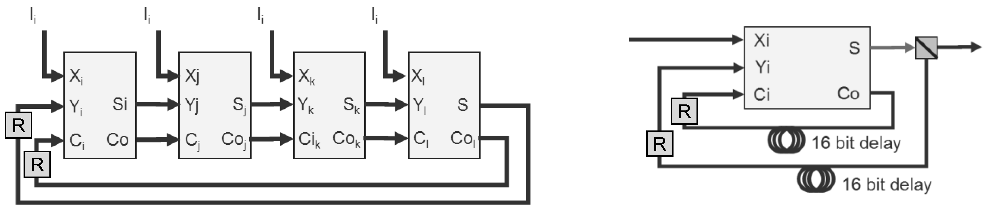
Over two decades ago, our team developed a 1.26 Gb/s IP checksum using a simple programmable logic device (PLD) [
21]. The device was composed of four 4-bit full adders, whose carries and data are cascaded in a cycle (
Figure 11, left). For an optical version, we propose using a single full adder with 16 bits of recirculation delay for both the data and carry (
Figure 11, right). This variant may also require data regeneration (‘R’ boxes in the right figure), depending on the number of 16 bit words being summed. For most IPv4 packets, the header is 20 bytes long, requiring the summation of 10 16-bit words, in which the partial sums and carries cycle 10 times. When the TCP or UDP checksum needs to be updated, as when a router supports network address translation, as many as 750 cycles of 16-bit words may be required (e.g., for a 1,500 byte packet). Our team has developed a proprietary variant of this design that requires only four cycles for the IP checksum (or 10 for the TCP or UDP checksum) to reduce the signal degradation that occurs during each cycle.
Implementation of this design requires the development of an optical one-bit full adder. Other teams have developed such a device for binary RZ encoded data [
22], and we are currently planning on implementing the IP checksum based on existing binary adders.
6. Optical Packet Multiplexing
The final phase of router processing is packet multiplexing, in which packets whose destinations have been determined, hop counts have been decremented, and checksums have been updated are switched towards the output port indicated by the forwarding lookup. This step also needs to include the possibility of output port contention (competition), possibly storing one of the competing packets to help the traffic more efficiently interleave.
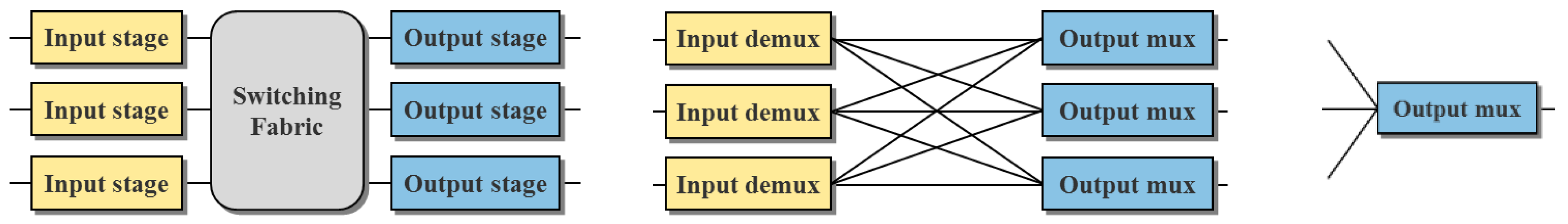
The basic high-level structure of a router includes input and output stages that correspond to input and output links, connected by a switching fabric (
Figure 12, left). One implementation variation of that structure adds a demultiplexer to each input stage and a multiplexer to each output stage, so that the switching fabric can be replaced by a fully connected internal mesh (
Figure 12, center). In this architecture, output port contention is handled in the output multiplexer, in which each output port’s multiplexing function can be implemented independently (
Figure 12, right).
We chose this latter architecture for our optical router for two reasons. First, it lets us focus on the multiplexing operation of each output independently, rather than considering that an internal function of the switching fabric. Second, the output multiplexer itself is useful as a traffic aggregator, such as would be useful in metropolitan access networks where traffic from many lower-bandwidth local networks is combined for long-distance transit. The case shown, with N inputs and outputs (assuming a symmetric capacity configuration), requires N2 internal bandwidth, and N output multiplexers each with N inputs, i.e., N2 merging elements. Other more scalable designs require only N internal bandwidth and N*log2N merging elements and are achieved by using these same output multiplexing components in multiple successive stages. Both approaches rely on the same basic output multiplexer function.
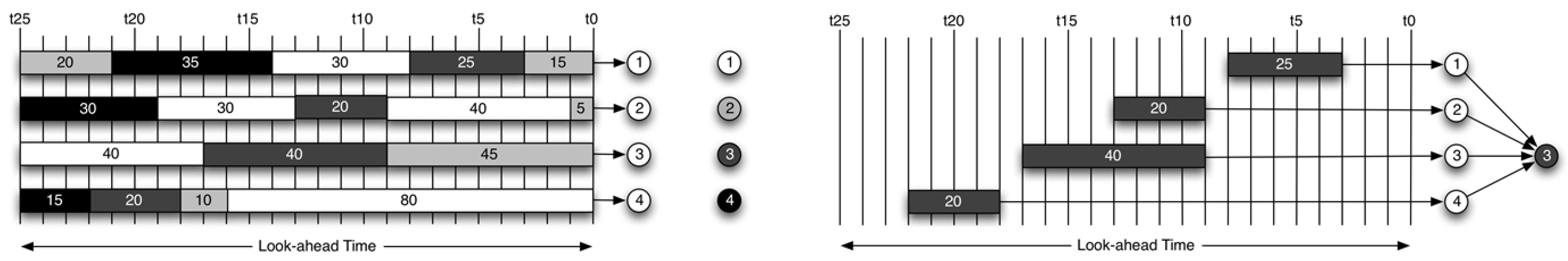
In the demux–mux architecture, we can examine packets destined to each output port as independent sets [
23].
Figure 13, left, shows a set of packets arriving at each of four input ports, shaded to represent their desired output port (based on lookup in the forwarding table). The numbers inside each packet indicate its length (in arbitrary units).
Figure 13, right, shows only those packets destined for output port #3; in the demux–mux design, these are the only set of packets that the port #3 output multiplexer needs to coordinate.
Within that set, some packets may overlap in time (the one of length 20 and the one of length 40, both starting at time
t9), whereas other packets might not overlap (e.g., the one at length 20 starting at time
t18). We call the set of packets that overlap the
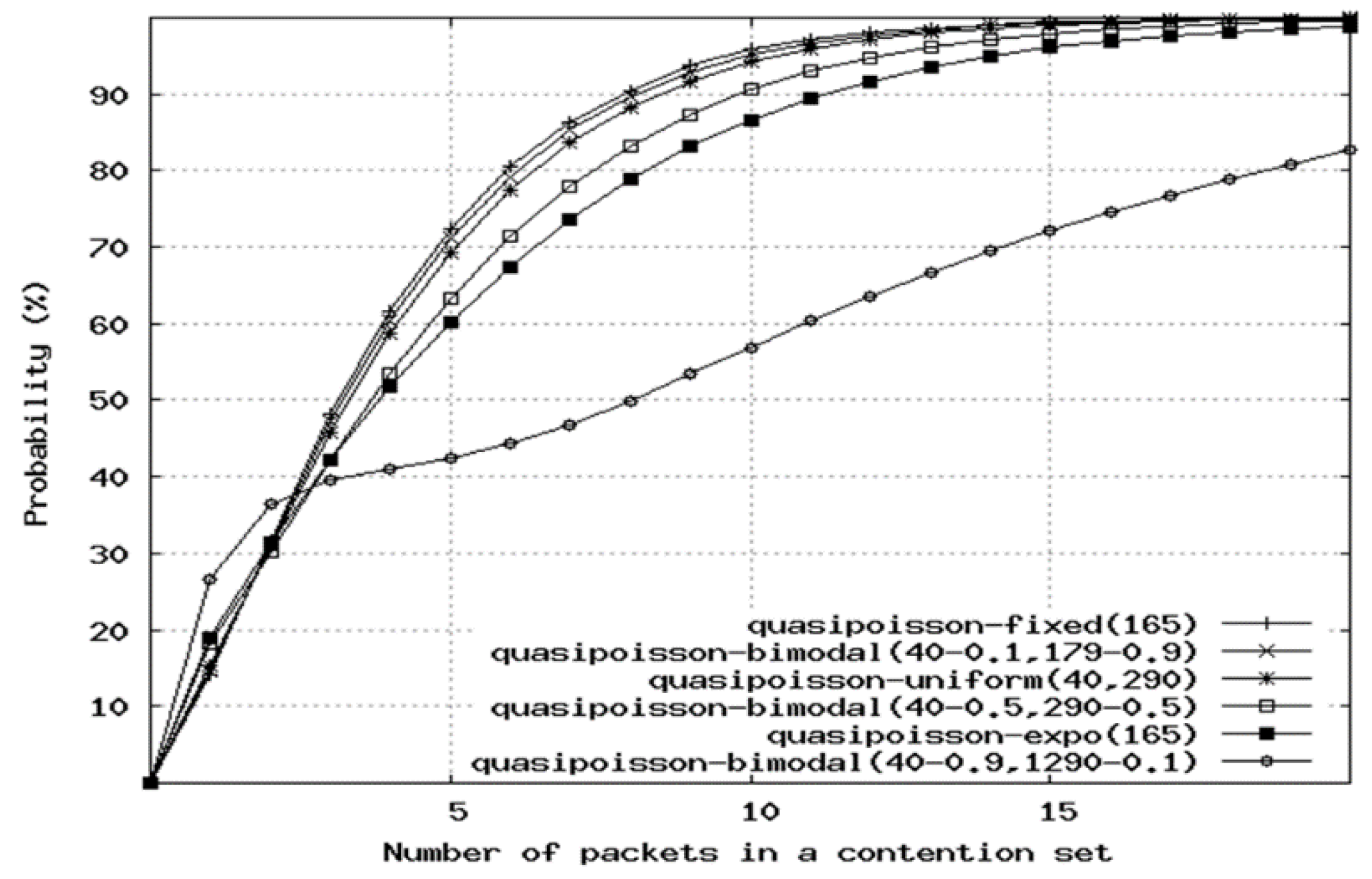
contention set. We measured the size of this contention set for generated traffic based on Internet characteristics [
24].
Figure 14 shows various types of such traffic and the cumulative probability of a set having a given number of packets; for most distributions, most of the contention sets include 10 or fewer packets. This suggests that the output multiplexer need not coordinate arbitrarily long sequences of overlapping packets, but that natural gaps occur in the packet stream, such that it is sufficient that only a few packets need to be scheduled at a time. This presents the opportunity for batch processing, which could enable a slower electronic scheduler to manage groups of packets. We call this batch scheduling interval the
lookahead time because it represents the set of packets that the multiplexer needs to “look ahead” in time to see, so that it can coordinate them as a set.
It is important to determine the limits of the effect of such batch processing. Within each batch, only a subset of packets may succeed in being multiplexed while others may need to be dropped, e.g., if the average output link capacity is exceeded for a long enough period of time. We performed extensive simulations to determine the difference between arbitrary (e.g., random) drop of contending packets vs. intelligent drop, the latter where the smallest number of the shortest packets (i.e., the fewest bytes total) is dropped [
24]. Our simulation configuration considered a 32 × 32 switch under various input loads from 10% to 100% per port activity and a variety of traffic patterns from Poisson (emulating highly multiplexed traffic, as is typical close to the core) to Pareto (emulating highly bursty traffic, as is typical closer to the edge). The simulator exhaustively considered every possible combination of packet drops, looking arbitrarily far into the incoming packet stream, determining the best choice in every case. We called this the “precognition switch” because it performs as if it knows the arriving traffic packet patterns arbitrarily far into the future. Regardless of preference, drops alone were shown to be insufficient, achieving only 65% efficiency, in which even the most intelligent precognition approach was only 3%–5% more efficient than arbitrary random drops (60%).
Efficient multiplexing thus requires time-shifting some of the packets, in order to better utilize the gaps between arrivals to compensate for overlapping arrivals and avoid drops [
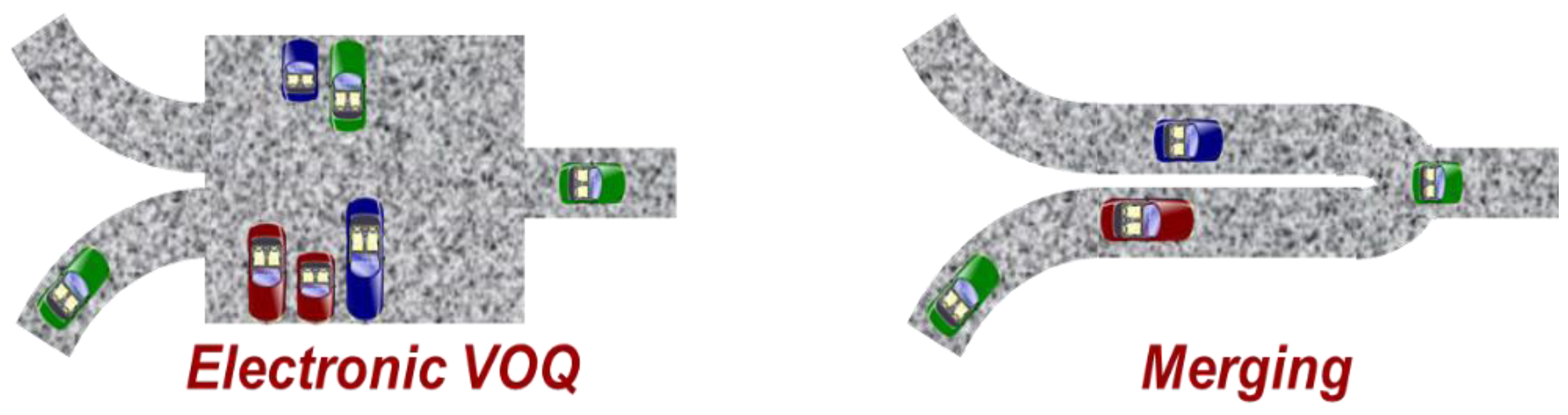
23]. Electronic packet switches accomplish this time-shift using queues. Queues are first-in, first-out buffering devices that help time-shift and sometimes reorder groups of packets. Electronic queues provide first-in, first-out behavior but are typically implemented less like waiting lines (e.g., ticket queues at the movie theater) and more like parking lots (random access storage). Arriving packets are placed into determined locations based on the packet type and arrival time. They remain parked in this lot until they are scheduled for release, in a process that is more like a valet retrieving the desired car than people completing a ticket purchase (
Figure 15, left). Common mechanisms for electronic queuing place these parking lots at the input stage, called Virtual Output Queuing (VOQ), in which packets are parked in separate groups destined for each output, such that packets are released to the output stage with no overlap, so the output passively merges the result. The two common electronic VOQ algorithms are iSLIP [
25] and Parallel Iterative Matching (PIM) [
26]; these provide the metrics against which we can evaluate optical queuing.
Although electronic packets can be parked arbitrarily long in random access memory (RAM), optical packets cannot be ‘stopped’ in this manner. Light can be slowed down, but not stopped. As a result, we consider a different approach to queuing, in which packets merge much as do cars on merging roads. Packets come together where they (or an external party) detect potential contention, and one car ‘hits the brakes’ so the cars merge passively without slowing down (
Figure 15, right).
The merging approach, based on gradual and selective slowing of packets, can be accomplished using a switched delay line (SDL) (
Figure 16, left inset). An SDL is a sequence of switches that select between a fast and a slow path, which can be implemented in optics using lossless Mach–Zehnder switches that select between waveguides with different refractive indices or of different lengths. Our approach assumes a small number (e.g., 10) of switches in series, with the same delay possible at each switch. This sequence of SDLs is sometimes known as a ‘staggered delay line’ [
27], which also behaves similarly to a ‘conveyor queue’ [
28].
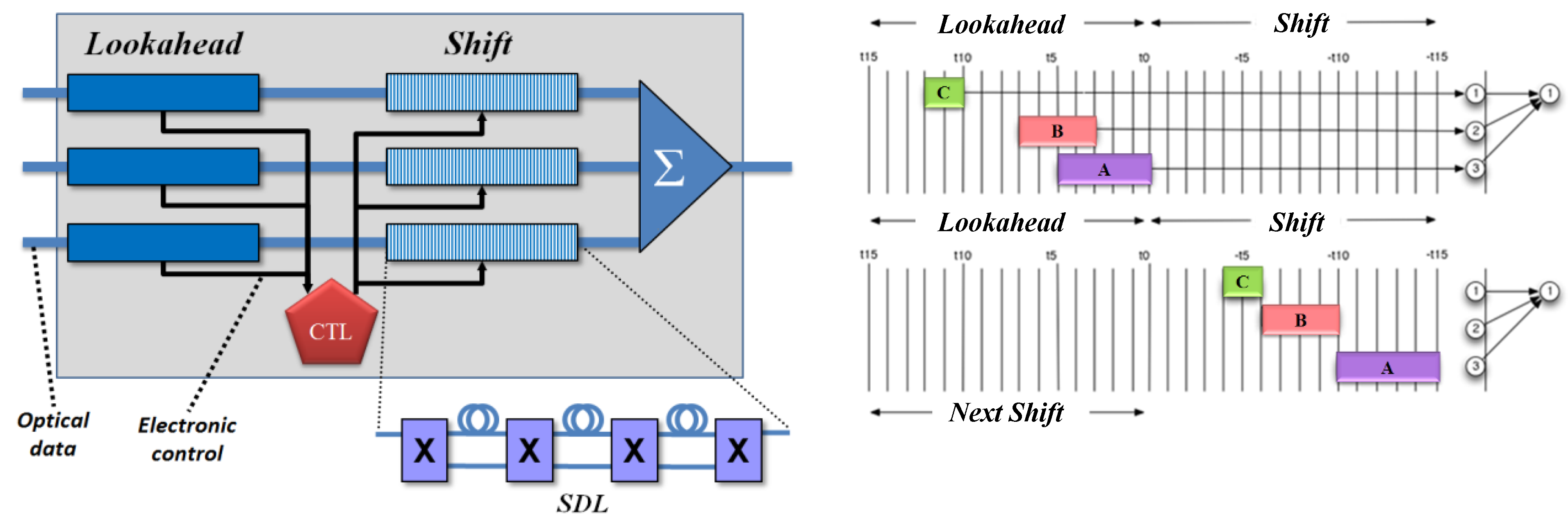
Our output multiplexer consists of two sets of delay lines—one fixed followed by one switched—of the same length (
Figure 16, left) [
23,
29,
30]. The fixed delay provides access to the headers of a batch of incoming packets, one line from each of the input demultiplexers. While in this
lookahead region, packet headers are sent to an electronic control that determines which packets to slow down and which to drop. The control configures the SDLs in the
shift region, and the packets are time-shifted to avoid contention. Each input line is allocated its own
lookahead and
shift regions, which together form a linear delay, so packets from a given input are never reordered. The resulting set of shifted packets is combined passively onto the output link.
Figure 16, right, shows this behavior for a set of incoming packets while in the
lookahead region (top) and after being aligned in the
shift region (bottom). We call this the ‘Tetris’ switch, named after the popular video game, because it is similar to the packing of blocks in the game when viewed horizontally [
29].
Batch processing of sets of contending packets in the lookahead region enables our approach to support a variety of prioritization algorithms, which “pack” the output port similar to classical bin packing algorithms. This prioritization also supports different types of packet quality-of-service (QoS), in which header priority tags or other properties (address, destination, protocol type) can determine which packets are shifted first, which should be dropped or not dropped, and which can wait for available capacity (e.g., network control messages, traffic that exceeds assigned capacity, packets assigned to guaranteed or reserved flows, and background capacity, respectively). For our measurements, we use a default algorithm in which packets are scheduled in the order they arrive, attempting to retain their relative arrival order.
We measured the effectiveness of this configuration in a 32 × 32 switch using simulations based on traffic properties closer to the Internet edge, where we believe packet switching will have the most significant impact [
23]. Such traffic is more bursty (Pareto) and thus more likely to benefit from statistical multiplexing gains. We measured the effective throughput of the switch under a variety of loads from 10% to 100%, using
lookahead and
shift buffer regions of varying sizes from 1500 bytes to 15,000 bytes, equivalent to 1–10 large IP packets. We assume the
lookahead and
shift region buffer sizes match, largely to simplify the number of variables considered.
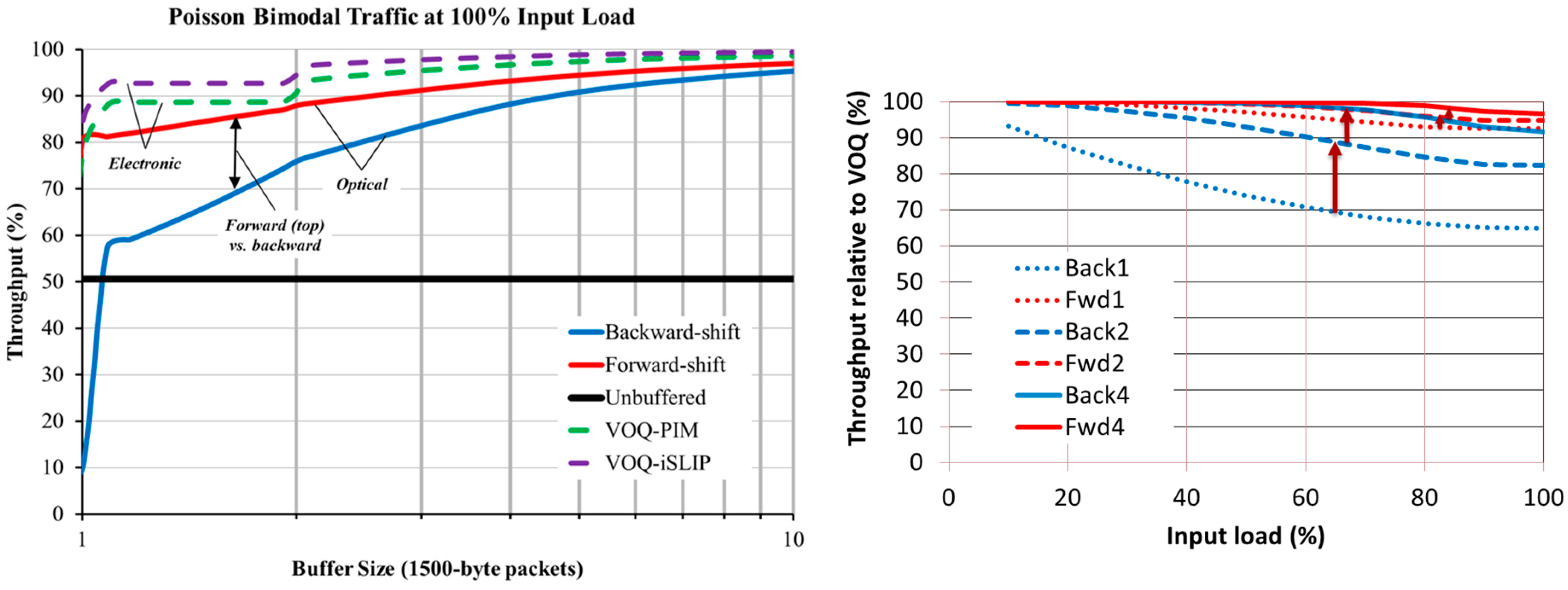
Our results at 100% load are shown in
Figure 17, both as absolute measures (left) and relative to VOQ iSLIP (right). We compared two electronic VOQ algorithms: iSLIP [
25] and PIM [
26], forward-shift, backward-shift, and no queuing (unbuffered). In backward shift (inspired by an architecture developed at the National Institute of Information and Communications Technology (NICT) [
31]), the SDL default is to select the fast path and packets are slowed down (take the longer path) when desired. In our proposed forward shift, the SDL default path is to select the slow path and packets are effectively sped-up (take the shorter path) when desired [
29,
30]. The results demonstrate that optical SDLs can achieve up to 95% of the efficiency of electronic VOQ with buffers as short as 6000 bytes (the equivalent of four large IP packets) [
23]; this result agrees with the new understanding that efficient Internet routing can be achieved with a comparatively small amount of buffering, rather than the conventional wisdom of a full round-trip bandwidth-delay product’s worth [
32]. The results also clearly demonstrate the difference between backward and forward shift approaches and show that forward shift is much more efficient, especially for smaller buffer regions.
Figure 17, right, shows the difference between backward and forward shifting under input loads varying from 10%–100% compared to VOQ iSLIP [
23]. It compares one, two, and four large IP packets’ worth of buffering and shows that forward shifting is much more efficient under all loads than backward shifting assuming the same amount of buffering. It also shows that forward shift achieves at least 95% of the efficiency of VOQ iSLIP under all loads.
7. Related Work
Two large surveys review high-performance router design [
33] and optical routers [
27]. High-performance router designs tend to focus on increased electronic parallelism, which does not support all-optical packet processing needed when communication bandwidths and distances necessitate optical transmission modulation formats. Many optical approaches focus on the expectation of reduced energy, although some attempt to refute that claim [
27]. Our approach makes no assertions as to the potential for energy savings for the optical approach; we assume that the primary benefit of an optical packet switch is avoiding the complexity and cost inherent in conversion from necessary optical transmission formats to electronic formats for switching.
A number of groups have attempted to develop optical packet switches. Most designs fall into two categories: recirculation and burst switching. Recirculation systems handle output port collision by sending colliding packets to a set of fiber delay lines (FDLs) of different delay, in which those packets are returned to the input for a new attempt at switching [
34,
35,
36,
37]. Recirculation causes packet reordering, which can severely affect some protocols [
38]. Some switches handle only fixed-sized packets that arrive aligned (synchronously) [
35], whereas others recirculate variable-length packets into FDLs of different length [
37] or have input ports with one FDL staging area for each output port [
39]. Our design shifts packets while in transit and each input is assigned its own SDL for each output, so it never recirculates them, thus avoiding packet reordering.
Optical Burst Switching (OBS) [
6] and Terabit Burst Switching (TBS) [
7] schedule groups of adjacent packets with the same destination as if they were brief circuits configured while the packets are in flight. They assume both that these groups can be created at the network edge, typically using large electronic buffers, and that these brief circuits avoid contention while in transit, sometimes by scheduled coordination of burst emission. We consider the delay introduced in gathering sufficient packets for a burst and the global coordination required to avoid burst contention untenable approaches to handling dynamic Internet traffic patterns. Furthermore, a burst is scheduled as a group, reducing the opportunity to schedule each packet individually and thus achieve higher multiplexing efficiency.
Some groups have recently revived use of more conventional optical circuits as a complement to packet switching, such as those that would use micro-mirrors, wavelength selection, or electro-optical switches (e.g., Pockels cells). This approach is already widely used commercially and can be very effective when traffic patterns are known sufficiently in advance, both early enough to mask large circuit setup delays to offset the dead time during circuit reconfiguration and involving enough data to warrant a dedicated optical channel. This is rarely the case for Internet traffic in general, but can be used for provisioning links between Internet routers in the Internet core (where traffic is large enough and where its backbone patterns are predictable in the aggregate), especially over long timescales. Known traffic patterns are also a hallmark of many data center applications, in which hybrid use of optical circuits can complement packet switching [
8]. Our approach avoids being limited to such environments.
Some groups have explored so-called ‘subwavelength’ fast optical switching to handle packets. These often focus on the switching mechanism itself, especially using wavelength conversion mechanisms. In most designs such as these, the header is assumed available out-of-band concurrent with the packet and is handled electronically [
40]. Our approach uses an all-optical data plane, including optical packet processing, and assumes a focus on switching rather than wavelength partitioning.
The closest optical packet switch architecture to our approach is the NICT design [
31]. Their architecture, like ours, supports variable-length packets without converting them internally to fixed-length packets. They too avoid the issue of wavelength conversion, focusing on a single-channel per port approach. Their design uses a fixed set of FDLs of different lengths to provide different delays, rather than our SDL approach. Our backward-shift configuration was inspired by their use of no delay as default and to add delay only when needed. Our forward-shift approach was inspired by the Tetris game, specifically the use of the ’space bar‘ to “drop” a block into place rather than waiting for it to drop more slowly. As described in
Section 6, our forward-shift approach is more efficient than the backward-shift inspired by the NICT design.
8. Discussion
This exploration demonstrates the need for an optical data plane for Internet routers and the viability of optical processing. For each component, including forwarding, hop count decrement, checksum computation, and multiplexing, we have demonstrated the feasibility of a relatively simple approach, either through experiment or simulation.
Practical optical header matching will depend on the ability to efficiently compress the forwarding table into a very small number of cached entries, each of which considers a fairly small number of bit values, and there is evidence that this may be feasible [
15,
16,
17]. The alternative would require both very large scale integration to support larger, more complete forwarding tables, as well as the ability to efficiently optically replicate packet headers to support a large number of concurrent correlators.
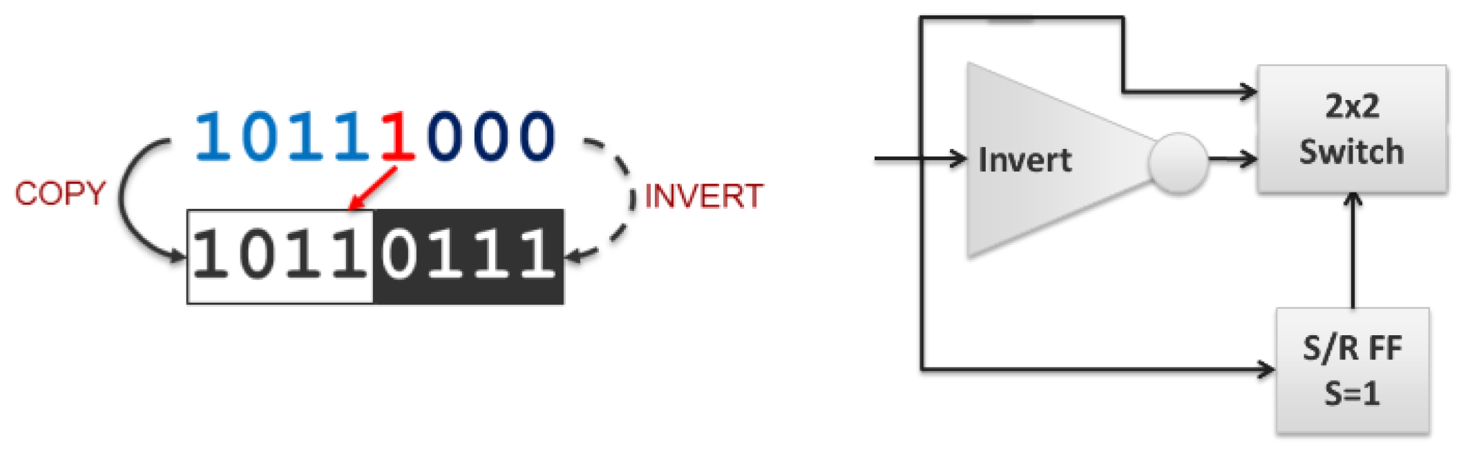
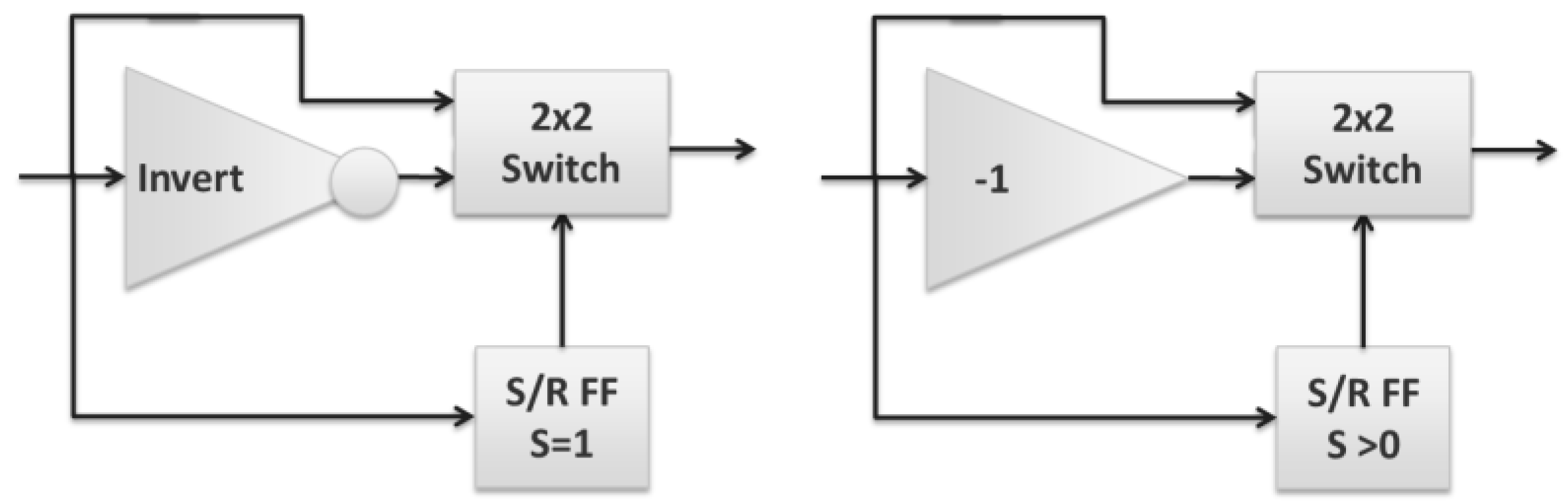
Internet hop count decrement is the closest to being immediately practical in optics. A more complete solution would require integration of an optical S/R FF, but the current approach is otherwise sufficiently simple and direct. It would additionally benefit from being extended to support multi-bit encodings, such as M-PSK or QAM, to natively support common high bandwidth, long-distance transmission formats. Using an M-PSK encoding changes the inverter to a ‘−1’ (subtract one) transform (‘−1’ is the same as conjugate generation for binary values, but requires a phase shift of 2π/M for M-PSK encodings) and changing the S/R FF from a binary device (
Figure 18, left) to one that treats the set input as either zero or nonzero (
Figure 18, right).
The Internet checksum may be challenging to implement in optics, but shows the promise of support for other checksum approaches, especially those that might be more directly tailored to optical processing. The two impediments for checksum development are signal integrity and extension to multi-bit formats. The checksum currently requires the partial carry and partial sum to be recirculated K times for a K-word input (for K recirculations, with one final recirculation to allow the carry to propagate through the final sum). This may be practical for the 20-byte default IPv4 header, but it would be difficult to extend to support packet rewriting that requires updating the transport layer (TCP, UDP) checksum over the full packet body. We are in the process of developing a proprietary mechanism that effectively folds the feedback loop, reducing the number of recirculations from O(K) to O(log(K)).
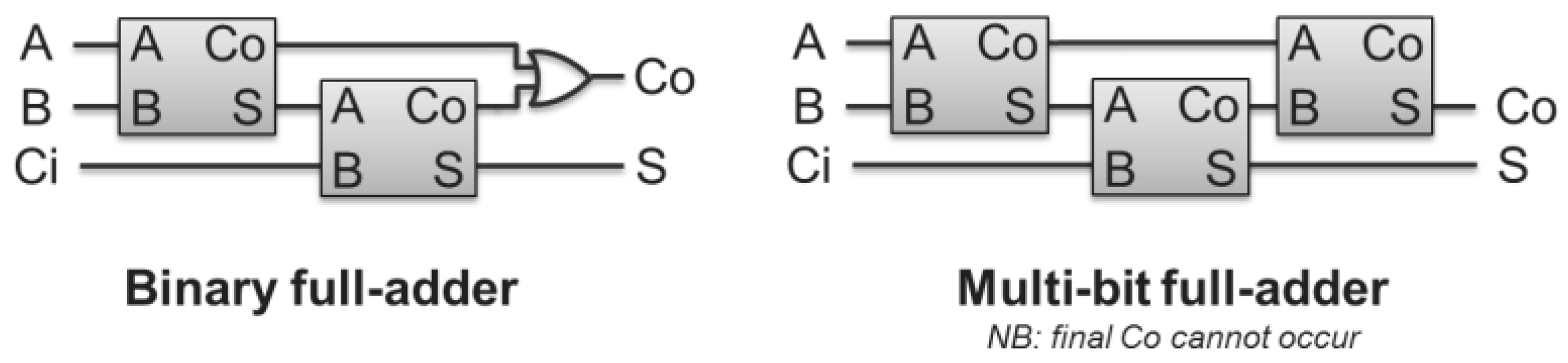
The checksum also needs to be extended from binary to multi-bit encodings. Although binary half- and full-adders have been demonstrated [
22], multi-bit adders, e.g., for M-PSK encodings, are currently limited to modular arithmetic [
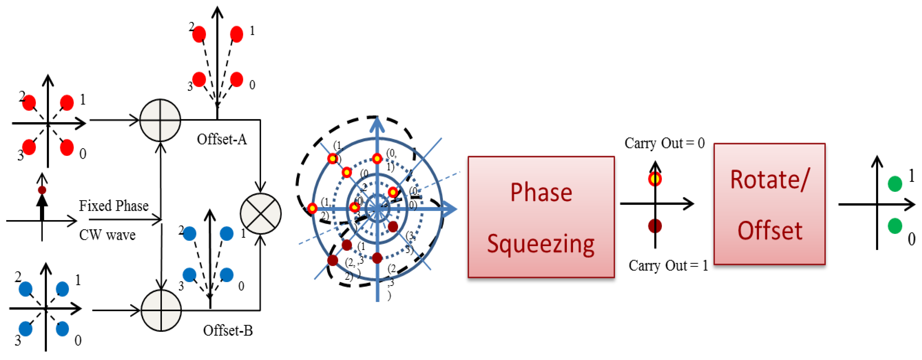
41]. Extending these to a full-adder requires concurrent carry-out generation, resulting in a half-adder, and composition of multi-bit half-adders to create a multi-bit full-adder. Our team has explored a potential approach to M-PSK carry generation, in which incoming signal phases are halved, added, then squeezed and shifted to create the corresponding carry-out value (
Figure 19, left to right) [
42]. Two binary half-adders can be combined, joining the carry-outs in an OR gate (
Figure 20, left), but it takes three multi-bit half-adders to create a multi-bit full-adder (
Figure 20, right).
Sufficiently efficient multiplexing can be implemented in optics using as few as 6000 bytes of optical delay. At low bandwidths, e.g., 10 Gb/s RZ encoding, this can be unwieldy (2.2 km), but as symbol rates and encoding density increase, this decreases quickly. At 40 G symbols/s using 8-PSK, 6000 bytes of delay is only 121 m; at 1 T symbols/s, the same delay requires only 5 m. It will be challenging to implement this delay in 10 equal units with as many low-loss switches in series. The switches are reconfigured each batch, so existing ~1 ns active device switching times should be sufficient.
The relationship between transmission formats and processing complexity also affects the feasibility of this approach. Current transmission formats, especially QAM, are optimized for robust transmission, but not necessarily for ease of digital processing. Our “Optical Turing Machine” project [
43,
44] is exploring whether other multi-bit encoding formats, notably M-PSK, might concurrently support high-bandwidth transmission while more feasibly enabling digital optical packet processing functions.
The major challenges are integration and regeneration [
44]. The component devices required by our approach are not individually novel; existing device designs are sufficient, but a practical optical data plane would need to be implemented as an integrated device, including existing designs for laser pumps, coherent comb sources, filters, couplers, and nonlinear wave mixing. Integration is required because it is not practical to support off-chip components, due to phase alignment requirements and signal loss. Combining this set of active and passive devices requires hybrid integration because no single substrate is sufficient. Regeneration is required to compose these separate functions into a processing pipeline, in order to avoid signal degradation that would increase the data error rate. For regeneration, our team has explored a number of approaches, including those requiring active phase stabilization [
45] and more recent methods using Brillouin amplification for phase restoration as well as Raman amplification that reduces amplification-induced phase noise, both of which avoid the need for active stabilization [
46,
47]. Hybrid integration is feasible but requires maturation of implementation technology, and regeneration will be more efficient and effective when implemented as a hybrid integrated system.


