1. Introduction
Wind power generation and its techniques have attracted increasing worldwide attention because of their effective reduction in environmental pollution, fossil fuel consumption, and the costs of overall electricity generation [
1]. Technology for wind power generation system is regarded to be much more mature than that of other distributed generation systems [
2]. Photovoltaic generation also develops fast due to low emissions, high durability, and low maintenance requirements. Its technology has been considered as another one of the most mature renewable distributed generations (RDGs) and widely applied as a mean to reach emission reduction with the increasing concern of environmental protection. However, they are characteristically fluctuating and intermittent. Their generated uneven power over time increases the difficulties in the controllability and dispatch ability. Consequently, serious challenges resulting from their integration to the grid are mounting on the power balance, system safety, and power quality [
3,
4]. In order to promote grid penetration capability and meet standard requirements for integration of renewable distributed generations, it’s necessary to apply appropriate allocation of distributed energy storage systems (ESSs) for decreasing negative effects on the grid that are brought about by fluctuating power and improving the power quality and system stability of the distribution network penetrated with such RDGs.
According to the related studies [
5], distribution systems suffer most from a frequency band from 0.01 Hz to 1 Hz of the fluctuating power output. Hence, the corresponding output power needs to be compensated with ESSs. Although lead-acid battery has been widely used because of the most mature technology and the lowest cost [
6], its lifetime is badly affected by frequent charging/discharging when used for compensating fluctuation of wind power output, especially deep discharging resulting in rising temperature of the equipment. The power-type ESS is quite different from the energy-type ESSs. Power-type ESSs, such as super-capacitor and superconducting magnet ESSs, have a high power density and quick response speed, but cannot have large energy capacity. While energy-type ESSs such as batteries have high energy density, its speed for compensating power is not ideal. While hybrid energy storage system (HESS) composed of the two types of ESSs that fully take advantage of their complementation can compensate for each other’s weaknesses [
3,
4,
7]. Consequently, researchers proposed [
3,
4,
7,
8,
9] an HESS that contains a supercapacitor and a battery; the supercapacitor with a quick response compensates for the output power fluctuation of high frequency, and the battery with high energy density compensates for the fluctuation of lower frequency. It is theoretically and experimentally proven that an HESS with an appreciable power allocation strategy allows for decreasing charging and discharging cycles and effectively compensates for the fluctuation of the wind power output. The key issue is how to reasonably allocate an HESS to balance the compensation effect and investment economy.
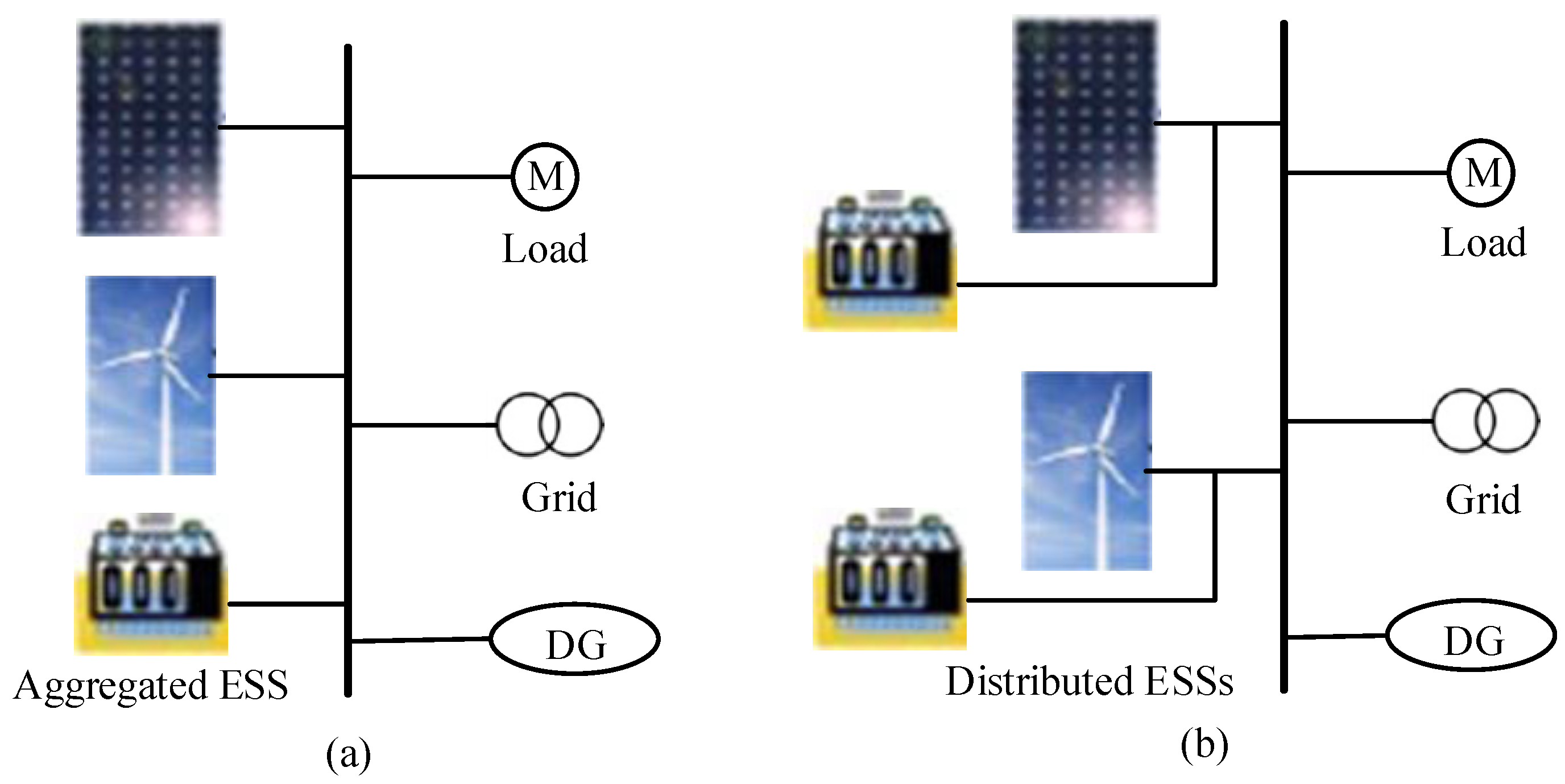
Basically, the configuration of an HESS is classified into aggregated and distributed [
10] as illustrated in
Figure 1. Simulation results demonstrate that the distributed configuration is as effective as aggregated in wind power smoothing and system frequency deviation reduction.
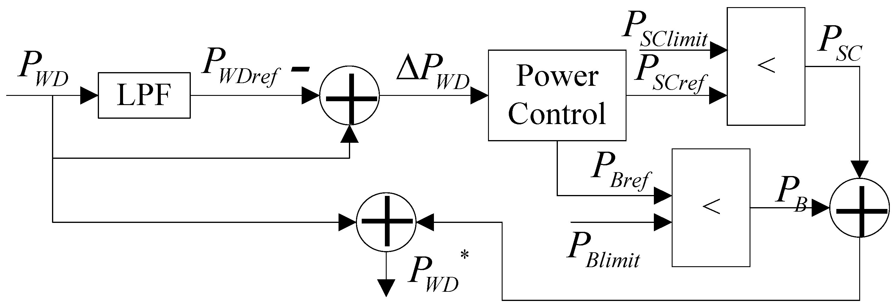
Figure 2 depicts the control diagram of a wind-HESS [
11]. The HESS implements power control and distribution according to the difference between the wind power,
PWD, and the reference power,
PWDref, that is computed via the low pass filter (LPF), and the state of charge (SOC) of each ESS device. The HESS output power,
PSC +
PB, either injects to or takes form the AC bus to compensate the wind power fluctuation, Δ
PWD =
PWD −
PWDref. Finally, we get the compensated wind power,
PWDCom. The rated capacity and power of each ESS clearly determine the power fluctuation compensation performance.
In order to investigate the compensation of power fluctuation of distributed generation with intermittent characteristics, and reasonably allocate HESS for balancing the compensation effect and investment economy, this study establishes a multi-objective model for optimally allocating HESS considering wind power generation, in which the objectives are to minimize the installation, operation, and maintenance costs and to maximize the satisfaction rate of power fluctuation compensation. Meanwhile, fuzzy control [
8] is introduced to optimally schedule the power output of each ESS for avoiding destroy the SOC limits, lengthening the battery lifetime, and ensuring HESS with enough energy to compensate the fluctuation of the next time interval. To provide the decision-maker with alternatives and to analyze correlations between optimization objectives, a multi-objective particle swarm optimization with integration of bacteria quorum sensing and circular elimination (BC-MOPSO) presented in [
12] has been applied to provide diverse alternative solutions. Numerical simulation along with discussion has been carried out to demonstrate advantages of the proposed model and effectiveness of the application of BC-MOPSO.
3. Computation of Reference Power Output of ESS and Power Accommodation for HESS
As stated in
Section 2.2, the actual power output of the ESS is computed via Equation (6) or Equation (7), in which its reference power output is determined taking into account the reference power of wind turbine and the SOC of each ESS device. On the other hand, compensation of the fluctuating wind power is realized through real-time control of the HESS power output. Consequently, suitable power accommodation strategy is important for enhancing the compensation effect. Fuzzy control is widely applied to accommodate the HESS for avoiding SOC limit violation. The process for computing the reference power output of each ESS is described as follows.
Firstly, estimate the SOC of each ESS using Equation (15) when charging or Equation (16) when discharging, and then apply them as the input of fuzzy control. Essentially, the two equations are used to compute the SOC after compensating the wind power with individual ESS.
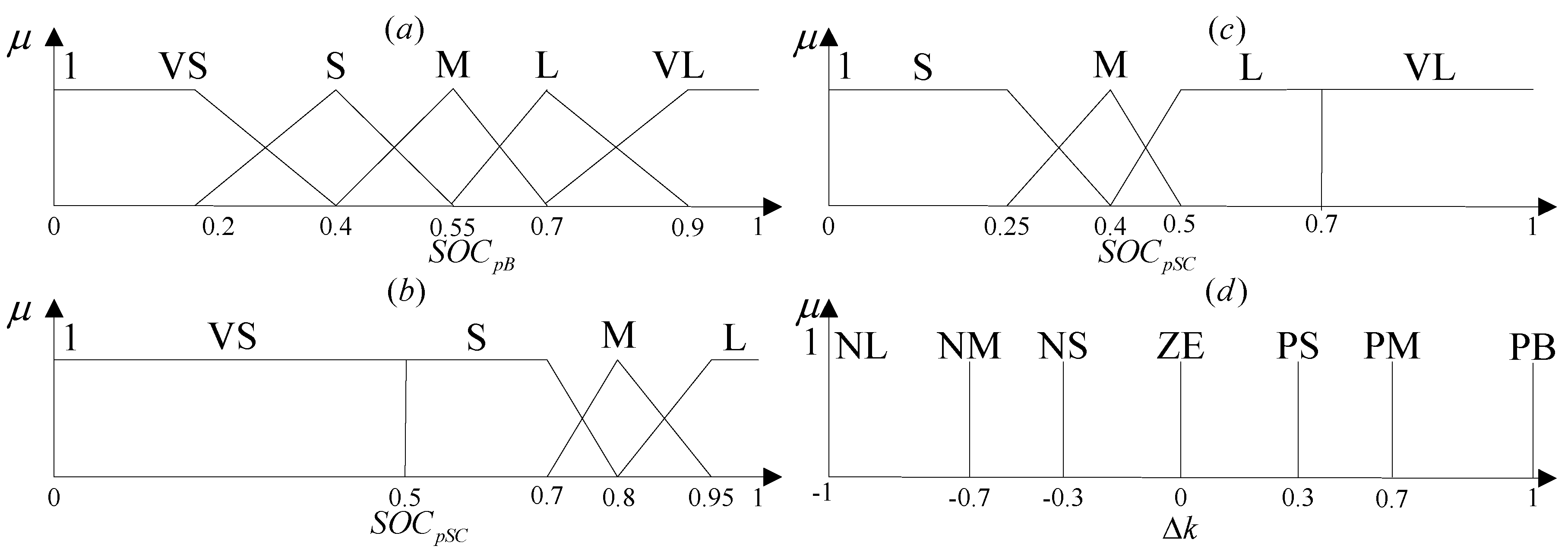
Secondly, get the membership value and determine the corresponding rule based on the membership function depicted in
Figure 3 and the fuzzy control rules illustrated in
Table 1 [
8,
9].
Thirdly, compute the modification coefficient for the power of ESS based on Equation (17) [
9,
13]. Finally, compute the reference power output of each ESS according to Equation (18).
Once the reference power output of each ESS is obtained, its real-time power output can be derived according to Equation (6) or Equation (7). Investigation from
Figure 3 and
Table 2, it is clear that the remaining energy in the supercapacitor is regarded to be adequate only when
SOCpSC ≤ 0.5 for Δ
PWD ≥ 0 and
SOCpSC > 0.7 for Δ
PWD < 0. And only in the two cases, the fluctuating wind power is compensated by the supercapacitor. The fluctuation is compensated by the battery and the supercapacitor when the remaining energy in the supercapacitor is insufficient.
4. Solution to the Multi-Objective Optimization of Allocating HESS
From the equations described above, it can be seen that the objective functions with technical and operational constraints are formulated. Appropriate optimization model considering multiple objectives of interest is essential for HESS configuration optimization. Such a model is worthless when it is optimized with an inaccurate optimization method. Traditionally, the multi-objective optimization problems (MOPs) have been solved by linear programming, and usually one of the objectives is optimized and the others are included in the restrictions or using fuzzy method and weighted aggregation approach where the MOP is converted into a mono-objective one. These methods simplify the optimization process of MORPO, but generate disadvantages [
14,
15]:
- (1)
Representation of the objectives using restrictions in linear programming can lead to unfeasible problems.
- (2)
There is not a clear criterion for choosing the suitable objective function, and in many cases the fulfilment of one single objective can be in conflict with others.
- (3)
Fuzzy optimization turns out to be a weighted aggregation approach with a set of stationary weights (preference factors).
- (4)
The weighted aggregation approach cannot accurately reflect the relationship between the various objectives, especially when the involved objectives are conflicted with each other.
- (5)
The only one best solution fails to provide the designer with alternative options.
Compared with mono-objective optimization (MOO) techniques, the main advantage of MOO is that a set of diverse optimal solutions are identified instead of one optimal solution, which gives more flexibility to the decision-maker. To offer a set of solutions to do tradeoff analysis and provide a deep insight into the multi-objective configuration optimization of HESS, effective MOO algorithms should be applied to this problem.
4.1. Discretization of the Decision Variables
Apply BC-MOPSO [
12] to solve the multi-objective optimization of allocating HESS. The BC-MOPSO algorithm was proved to outperform the other algorithms on convergence while maintaining a good spread performance, and can be used as an effective global optimization tool. In the real number space, each individual potential solution can be modeled as a particle that moves in the problem hyperspace, each particle
i is associated with its velocity
vi = [
vi1,
vi2, …
viD]
T and position
xi = [
xi1, xi2, …,
xiD]
T, where
D stands for the dimensions of the decision space. Suppose the position of each particle ranges between 0 and 1, its corresponding relation to the decision variables can be described by Equation (19). Assume the unit rated power and energy of the ESS are
Purated and
Eurated, respectively. Their corresponding relations with respect to
x are illustrated as Equation (20).
4.2. Computation of the Objective Functions
One of the important steps in the solution of the multi-objective optimization of allocating HESS is to evaluate an allocation solution, namely, compute the objective-function value corresponding to the solution or the fitness value of the corresponding particle. Suppose the swarm size is
P. Evaluation of the swarm can be summarized as follows.
- (1)
Initialize each particle, discretize the power and energy of each ESS according to Equation (20). Initialize P0WD*, E0SC, and E0B, set p = 1 and t = 1.
- (2)
Read PtWD, Pt−1WD*, Et−1SC, and Et−1B, compute PtmaxSC and PtmaxB based on Equation (6) or Equation (7), and get PtWDref according to Equation (9).
- (3)
Estimate SOC of each ESS at the end of interval
t, based on the membership function illustrated in
Figure 3, compute
bt according to Equation (17).
- (4)
Calculate PtSCref and PtBref according to Equation (18).
- (5)
Determine PtSC and PtB based on Equation (4) or Equation (5) and further get PtWD* = PtWD + PtSC + PtB. Compute EtSC and EtB according to Equation (1) or Equation (2).
- (6)
Derive SOCtSC and SOCtB according to Equation (3) and get ηt based on Equation (8).
- (7)
Assess t equals Nt or not, if yes go to Step (8), else make t = t + 1 and go to Step (2).
- (8)
Compute the objective-function values of the solution p.
- (9)
Judge p = P, if yes go to the next, else make p = p + 1 and go to Step (2).
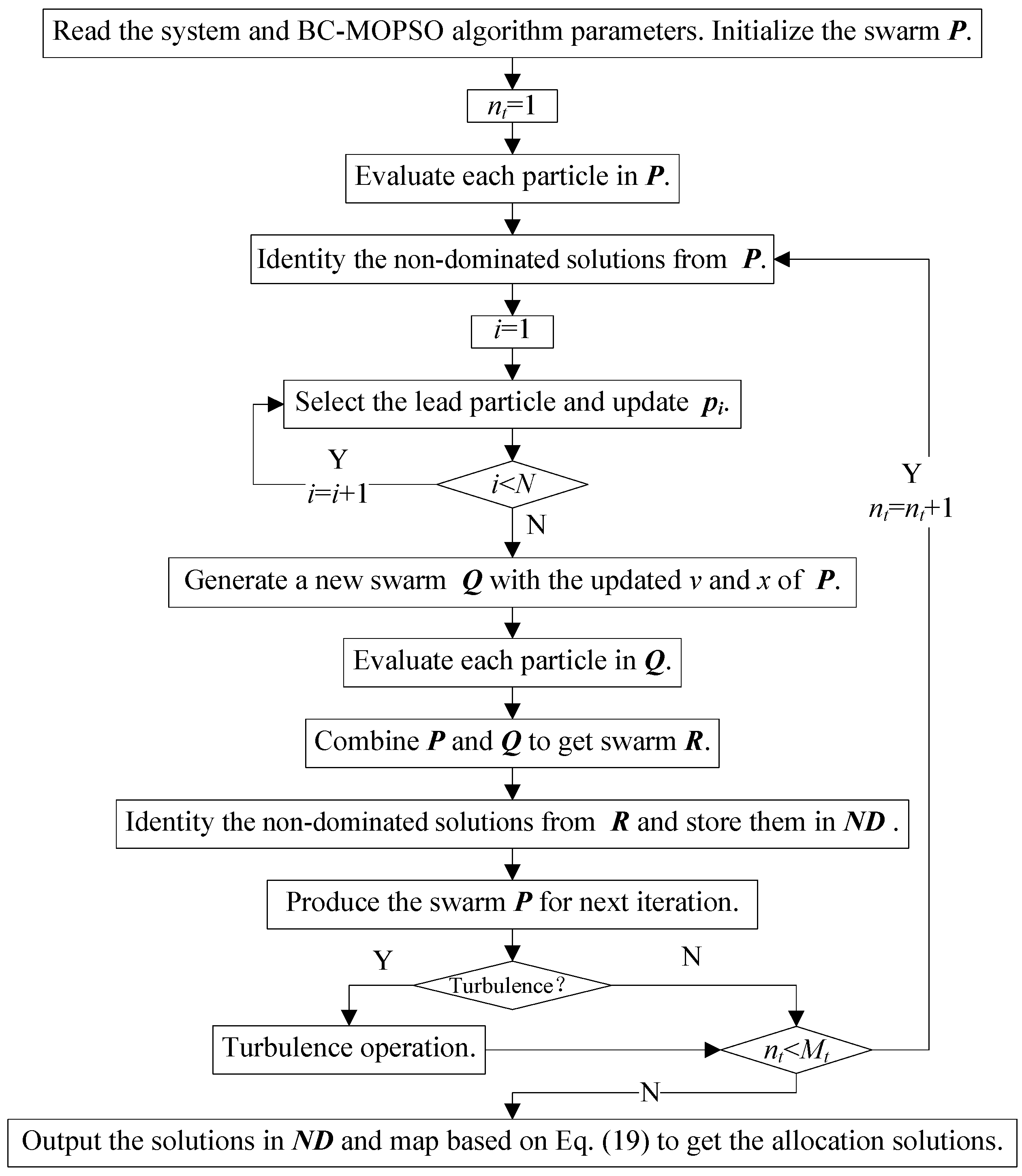
4.3. Application of the BC-MPSO Algorithm
Solving the multi-objective optimization of allocating HESS is to apply BC-MPSO algorithm to identify the optimal allocation solution(s). The detailed procedure of the algorithm can be described as follows and its application can be illustrated in
Figure 4.
5. Simulation and Analysis
Numerical simulations are carried out based on Matlab/Simulink. The allowed depths of discharge of the superconductor (SC) and battery range from 0.25 to 0.95 and 0.2 to 0.9, respectively. Their self-discharge rate is 0, an initial SOC is 0.55, and charge efficiencies are 100% and 80%, respectively. In addition, their unit-rated capacity is 1 MW, and charge/discharge power are 0.1 MW and 1 MW, respectively. The other characteristic parameters are listed in
Table 2 [
16,
17].
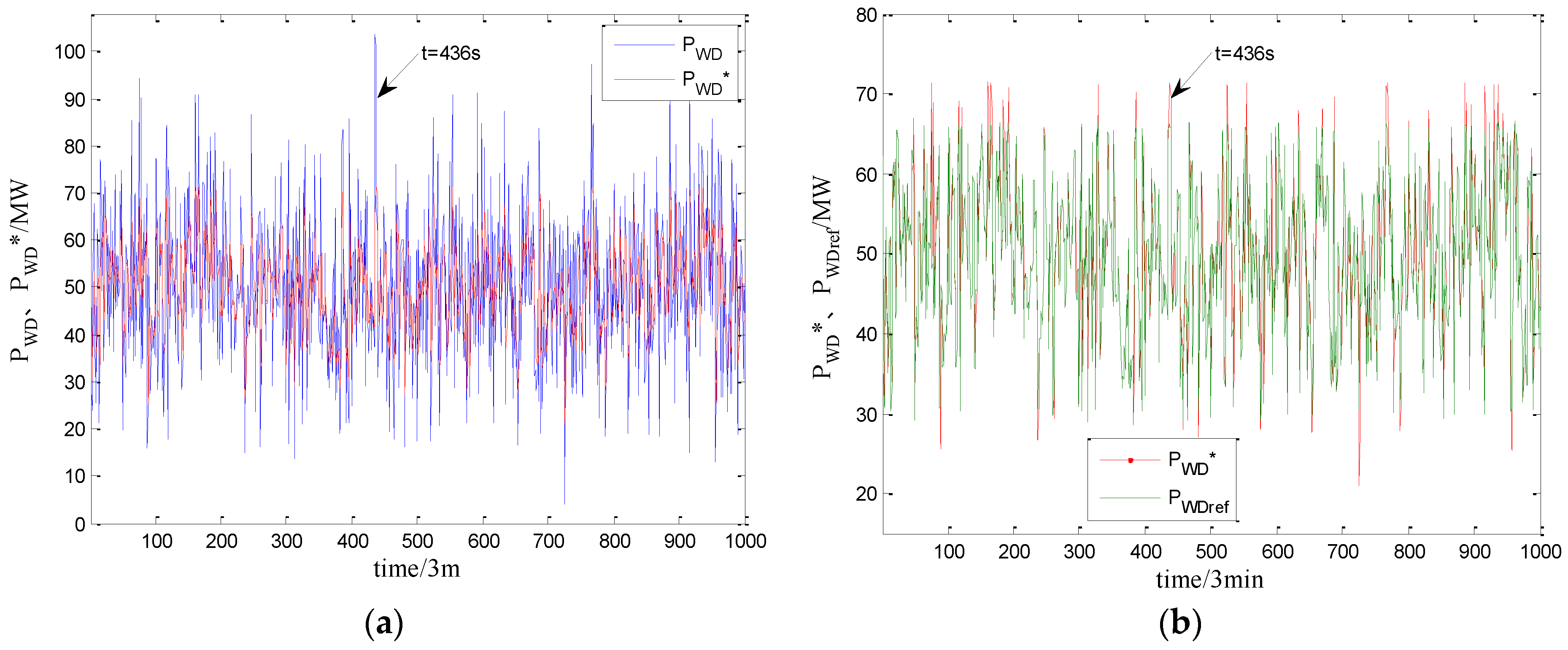
The wind power is illustrated in
Figure 6 that supposes it is of normal distribution with a mean of 50 MW and a variance of 15 MW. Apply BC-MOPSO to determine the rated capacity and power of each ESS, and the configuration solutions and their corresponding objective-function values are listed in
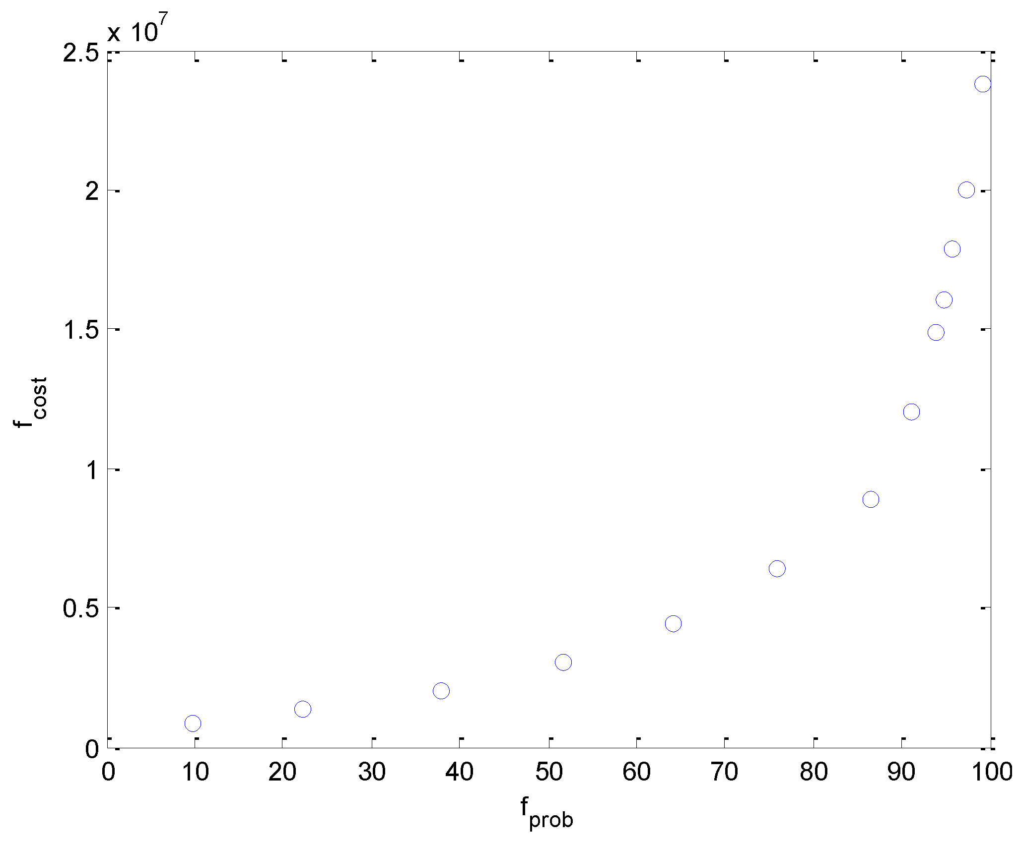
Table 3. The distribution of Pareto solutions in the objective-space are demonstrated in
Figure 5.
From
Table 3 and
Figure 5, it is evident that the rated capacity and power of each ESS increase with increasing satisfaction rate of wind power fluctuation compensation. Especially, when the satisfaction rate is larger than 93.91%, the HESS cost is remarkably increased. To analyze the compensation effect, take the 9th solution as an example.
Figure 6 demonstrates the comparison between the compensated and uncompensated wind power.
Investigation from
Figure 6, it is clear that HESS dramatically reduces the fluctuation of wind power output, and 94% of |
η| is less than 2%. However, for some period, the difference between the compensated wind power and the reference power is rather large. For example, when
t = 437 s,
PWDref = 66.25 MW: When
t = 436 s,
PWD is quite large, which leads the SC and the battery to charge and their SOCs to be high. As a result, HESS fails to well compensate the fluctuating wind power that produces a compensated wind power output of 70.63 MW.
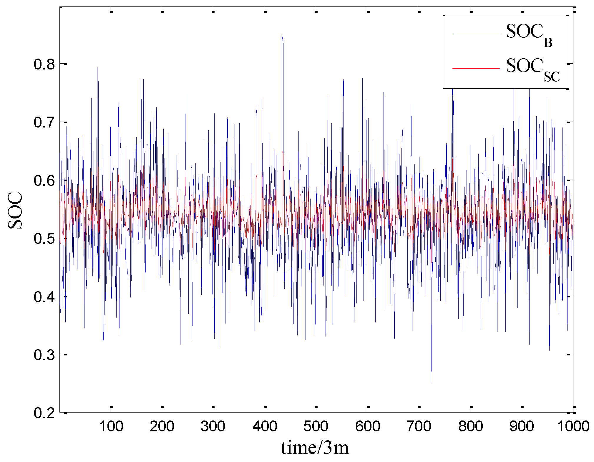
Figure 7 depicts the dynamic SOCs of the SC and battery, respectively. Clearly, their SOCs are controlled within a reasonable range that avoids making a bad effect on the lifespan of the ESS resulting from saturated and exhausted states.
6. Conclusions
Taking compensation of wind power fluctuation, for example, the study developed the multi-objective configuration optimization of HESS to compensate the fluctuating power output of the intermittent DG, in which the HESS is composed of a supercapacitor and battery. For maximizing the stability of the wind power output with minimized HESS investment, along with fuzzy control that is used for HESS power allocation, a multi-objective model for optimal HESS configuration was established to decrease the installation, operation, and maintenance costs of HESS and to improve the compensation satisfaction rate of wind power fluctuation. With the application of BC-MOPSO, a set of Pareto solutions were identified to provide diverse alternative configuration solutions, from which the decision-maker can make a choice according to the requirements of investment and compensation performance. The Pareto front demonstrate the relation between the power fluctuation compensation effect and the total installation, operation, and maintenance costs of HESS based on which the compensated power quality and the HESS investment economy is compromised along with the configuration of the HESS. The simulation results also demonstrate that the power allocation strategy with the application of fuzzy control enables to effectively reduce the fluctuation of the output power. Meanwhile, the SOC of the ESS is controlled within a reasonable range, which avoids negative effect on its lifetime resulting from saturated and exhausted states.


