Article

Heat Flow Characteristics of a Newly-Designed Cooling System with Multi-Fans and Thermal Baffle in the Wheel Loader

1
Department of Mechanical and Electrical Engineering of Xiamen University, No. 422 Siming South Road, Xiamen 361005, Fujian, China
2
Xiamen XGMA Machinery Co. Ltd., No. 668 Xiagong Machinery Industrial Park, Guankou Town, Xiamen 361023, Fujian, China
*
Author to whom correspondence should be addressed.
Appl. Sci. 2017, 7(3), 231; https://doi.org/10.3390/app7030231
Submission received: 19 December 2016 / Revised: 26 January 2017 / Accepted: 15 February 2017 / Published: 1 March 2017
(This article belongs to the Special Issue Advances in Thermal System Analysis and Optimization)

Abstract

:
In the traditional cooling case, there is usually one fan in charge of heat transfer and airflow for all radiators. However, this seems to be inappropriate, or even insufficient, for modern construction machinery, as its overall heat flow density is increasing but thermal distribution is becoming uneven. In order to ensure that the machine works in a better condition, this paper employs a new cooling system with multiple fans and an independent cooling region. Based on the thermal flow and performance requirements, seven fans are divided into three groups. The independent cooling region is segregated from the engine region by a thermal baffle to avoid heat flowing into the engine region and inducing an overheat phenomenon. The experiment validates the efficiency of the new cooling system and accuracy of simulation. After validation, the simulation then analyzes heat transfer and flow characteristics of the cooling system, changing with different cross-sections in different axis directions, as well as different distances of the fan central axes. Finally, thermal baffles are set among the fan groups and provided a better cooling effect. The research realizes a multi-fan scheme with an independent cooling region in a wheel loader, which is a new, but high-efficiency, cooling system and will lead to a new change of various configurations and project designs in future construction machinery.

1. Introduction

In construction machinery, the heat-dissipating components always include an engine radiator, intercooler, hydraulic oil radiator, and torque converter radiator, and these share about 30 percent of the total engine power [1]. Take an ordinary loading machine for instance; total heat dissipating capacity is about 100 kW, which may even be up to 200 kW in some very large loaders [2,3]. The stricter fuel consumption and emission regulations put the worldwide carmakers and suppliers under pressure to develop more efficient thermal management systems. Mahmound built up simulation-based vehicle thermal management system concept and methodology [4], whereas Li designed a high-precision performance test bench to study the automotive cooling system [5]. Torregrosa focused on the warm-up period performance of the cooling system [6], but Tong focused on the radiator of system key component [7]. All researches are aiming at the strong, but efficient, cooling project to ensure all radiators operate in good conditions, so that a key issue for a construction machinery plant is matching a suitable and reliable cooling system in the machine design program.
In the traditional cooling case, there is usually one fan responsible for heat transfer and airflow for all radiators [8]. However, this seems to be inappropriate, or even insufficient, for modern construction machinery [9,10]. Due to energy savings and emission reduction, the machine tends to be lightweight and small in size, with the same power. Consequently, its overall heat flow density is increasing but its thermal distribution is becoming uneven [11]. If just one fan is still adopted, the fan should be of a large size and high rotating speed for supporting a large amount of cool air across the radiators for heat dissipation. This will lead to two new problems. One is that a large fan goes against the demand of light weight for modern machines. Another is that a high rotating-speed fan will greatly increase noise emission, while many national decrees are promulgated to restrict equipment noise for environment and operator health protection [12]. Therefore, in the requirements of increased power density, uneven thermal problems, engine compartment constraints, and working demands, the challenge now is how to ensure sufficient air flow, but maintain low noise emission for a cooling system. There are different ways, such as using electric coolant pump [13], or using integrated configuration [14], and one of the ways is adopting multiple fans.
The cooling system with multiple fans has some advantages. First, it can enhance heat dissipation, since it benefits from the independent design of each radiator, such as its power, rotating speed, cross-section, size, and so on. Second, as each fan can be different in size and working parameters, it can improve thermal unevenness problem. Third, as not all radiators are arranged together anymore, they can be flexible configurations to satisfy various engine compartments. Stephens studied heat exchanger flow interactions of multiple fans and found that it, indeed, performed well [15]. Zhang used two fans in a tracked vehicle and each fan can be controlled independently. The fan speed reached a maximum 5200 rpm on a hot summer day, while the fan usually worked at a speed of 3000 rpm [16]. Fu used multiple fans with an auto temperature-controlled system in a large bus and decreased fuel consumption by 8% per hundred kilometers, both in null and full loads [17]. Sun imported a multiple fan scheme into a meter-rail motor train and found it was useful in a limited engine compartment situation [18]. Zhang found that adopting multiple fans could not achieve a good heat transfer effect in the old cooling system with all of the radiators together and, thus, it should alter its original configuration and separate the fans into different parts as well as radiators [19].
As described above, multi-fan designs have been used in many fields, and proved to be a good strategy for system cooling. However, there are few articles or reports about construction machinery with multi-fans, especially in wheel loaders. Therefore, this paper employs a new design cooling system with seven fans for a wheel loader, which is validated to be efficient by simulations and experimental tests.
Meanwhile, in our previous research [20], it was found that there was energy stacking on the top of the engine and radiator due to heat air backflow, which caused a partial overheat phenomenon and increased the thermal damage to components in this area. At that time, as the components in engine compartment were kept in their positions, and they were forbidden to move, setting choke plates and adding an exhausting air outlet to optimize the airflow were suggested. The improvement decreased the system temperature by about 3 °C in practical experiment. However, this method was a partial correction and cannot radically eliminate heat stacking in the engine compartment. Therefore, this paper will arrange all radiators and fans into an independent cooling region segregated from the engine region by a thermal baffle in the system.

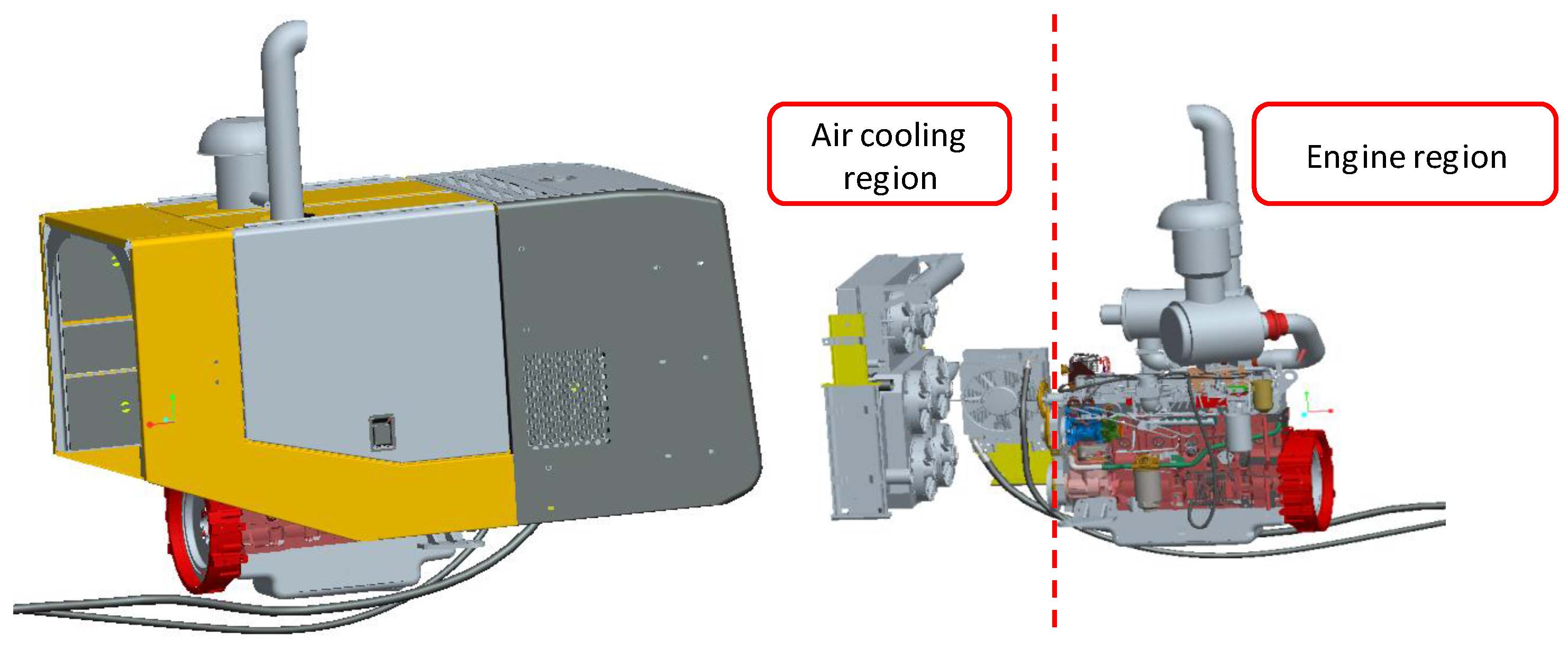
2. New-Design Engine Compartment

The heat dissipating components of a wheel loader demonstrated in this paper consist of an engine radiator, intercooler, hydraulic oil radiator, and torque converter radiator, and the respective heat loadsare 75 kW, 26 kW, 26 kW, 50 kW, where total heat dissipating capacity is 177 kW. The thermal load of each radiator is of primary consideration when matching the fans and their rotating speeds.

2.1. Fan Design and Matching

According to the system thermal flow, as well as radiator configuration and performance requirement, seven fans are adopted in this loader and they are divided into three groups. Two of them are used for the torque converter oil radiator in upper area of independent cooling region, four of them for the intercooler and engine radiator down from the torque converter oil radiator, and the last one for the hydraulic oil radiator on the side of independent cooling region, which are shown in Figure 1 and Figure 2. The distributed arrangement of the fans benefits from the independent design of each radiator, such as its power, rotating speed, cross-section, size, and so on. Here, we choose the same size and dimension, but different rotating fan speeds to form our cooling groups due to the limitation of power request, space restriction, and noise emission, which is shown in Table 1.

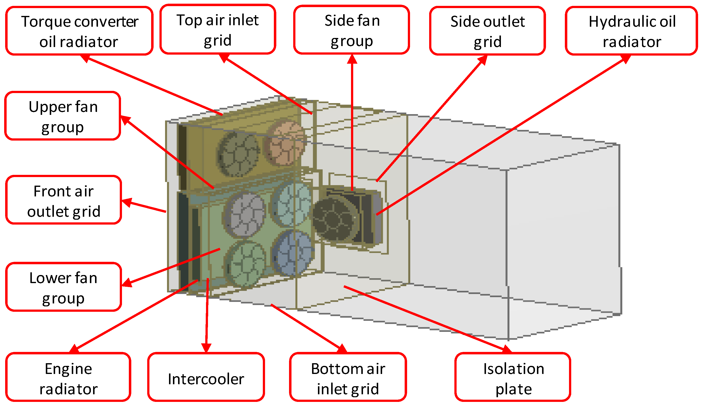
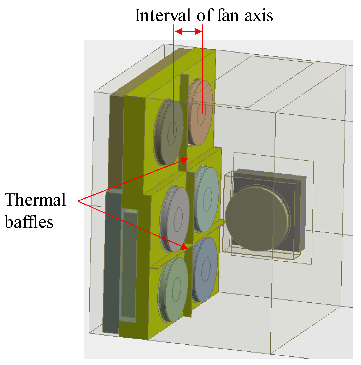
2.2. Flowing Channel Design

Since there was heat stacking on some regions in the engine compartment due to air backflow, a thermal baffle is set to segregate the cooling area into an independent region and prevent heat flow into the other region. Thus, the engine compartment is divided into two regions: cooling system area with all radiators and fans and engine area with the other components, which, at the extreme, avoids hot air blowing into the engine region and causes an overheat phenomenon. Then the flowing channel is also rearranged. There is not only one inlet and one outlet. As described above, an additional outlet will produce extra hot air flowing away from engine compartment, so that two outlets are set here and one is on the front of engine compartment whereas the other is on the side. Meanwhile, there are also two inlets in order to ensure enough airflow from the environment and one is on the top of the engine compartment whereas the other is on the bottom. The whole configuration is shown in Figure 2. More inlets and outlets are not suggested because they will induce greater air interaction and turbulent flow, which is bad to heat dissipation.

3. Simulation of the Engine Compartment

In heat coupled with flow simulation, it is based on the continuity equation first.
ρ t + ( ρ u ) x + ( ρ v ) y + ( ρ w ) z = 0
Then comes with kinematic equations (N–S equations).
( ρ u ) t + div ( ρ uu ) = div ( μ gardu ) p x + S u
( ρ v ) t + div ( ρ vu ) = div ( μ gardv ) p y + S v
( ρ w ) t + div ( ρ wu ) = div ( μ gardw ) p z + S w
Finally, energy conservation equation is used.
( ρ T ) t + div ( ρ uT ) = div ( k C p gardT ) p x + S T
where: ρ is density; t is time; u, v and w are the velocities in x, y and z coordinate axis respectively; μ is dynamic viscosity; p is pressure; S u ,   S v and S w are generalized sources; C p is heat capacity; T is temperature; k is heat transfer coefficient; S T is thermal energy induced by fluid inner heat and heat power due to viscidity action.

3.1. Model Building

The model building and mesh generation should balance simulation reliability against computer calculation process. The more particular the model is and the more grid number is, the more reliable the simulation is but the longer calculating time needs. Hence, keep the details of radiators, cooling fans and engine cover as many as possible, and simplify the other components as much as possible.
The 3-D model of the engine compartment in Figure 1 is built in SolidWorks based on the real engine system. Then, we import the model into the ANSYS Workbench for simulation. Before meshing, the model is simplified by the following procedures: erasing all chamfers and circular beads except those of fans; replacing bolts and gaskets by solid blocks; redrawing engine compartment into a shell with a specific thickness and using air envelope region instead of cooling fans.
After model simplification, we use the Enclosure Tool to set up a rotating air domain enveloping cooling fan and its neighborhood to replace fan entity, which benefits calculation process but also maintains computational accuracy.
As the cooling system is arranged in an isolated region, the focus is put on this area. We use Enclosure Tool to undertake Boolean Calculation for the entities in this area, and build the finite element analysis model as shown in Figure 2, including four radiators, seven fans, two inlets and two outlets.
Finally, we build up an air domain enclosing the engine compartment as the simulated outside working environment. The bottom surface of air domain is about 0.5 m far away from the bottom of engine compartment according to the real construction machinery. Taking the computational accuracy and efficiency into consideration, the other surfaces are about 1 m far away from the corresponding surfaces of engine compartment referring to Paper 21.

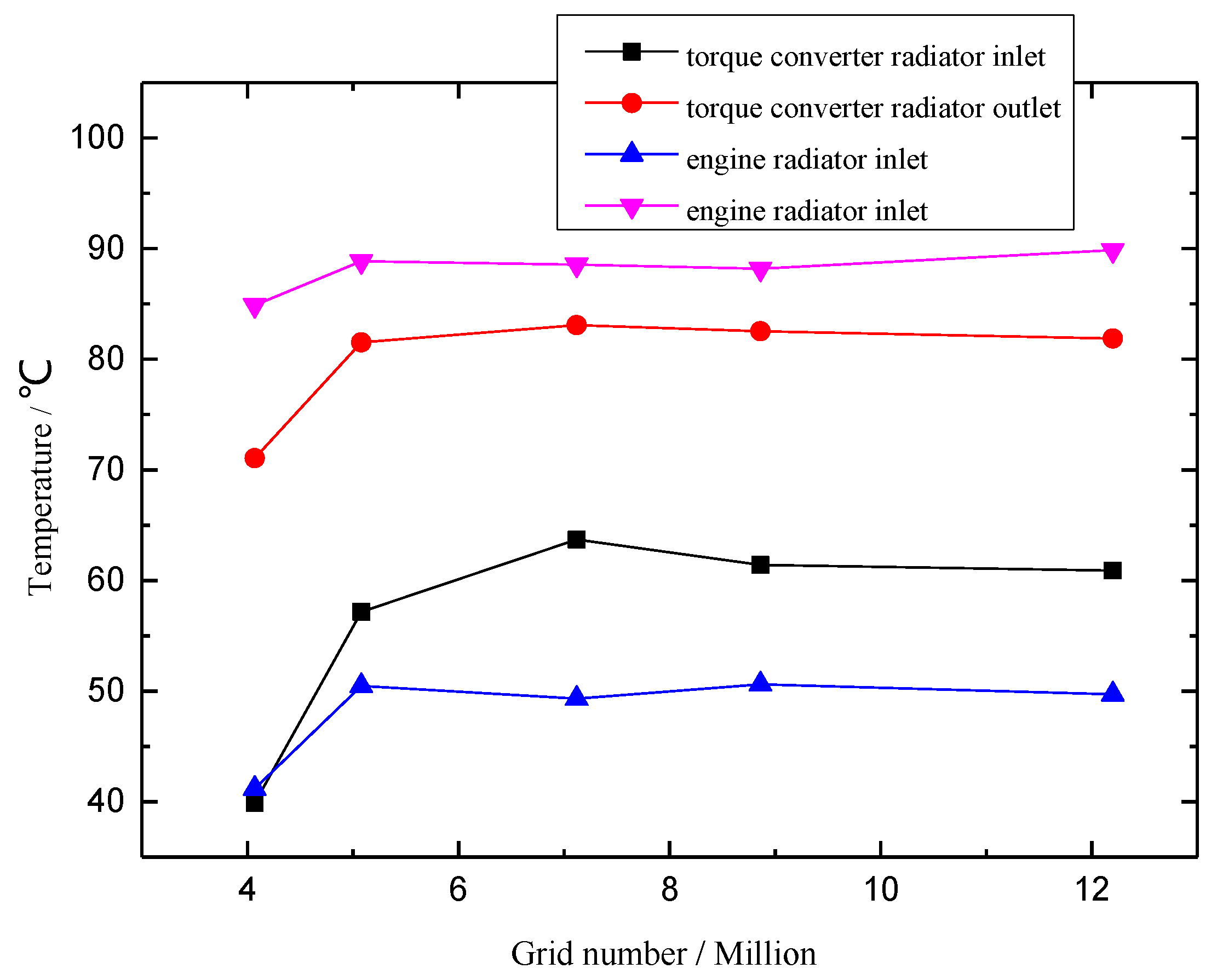
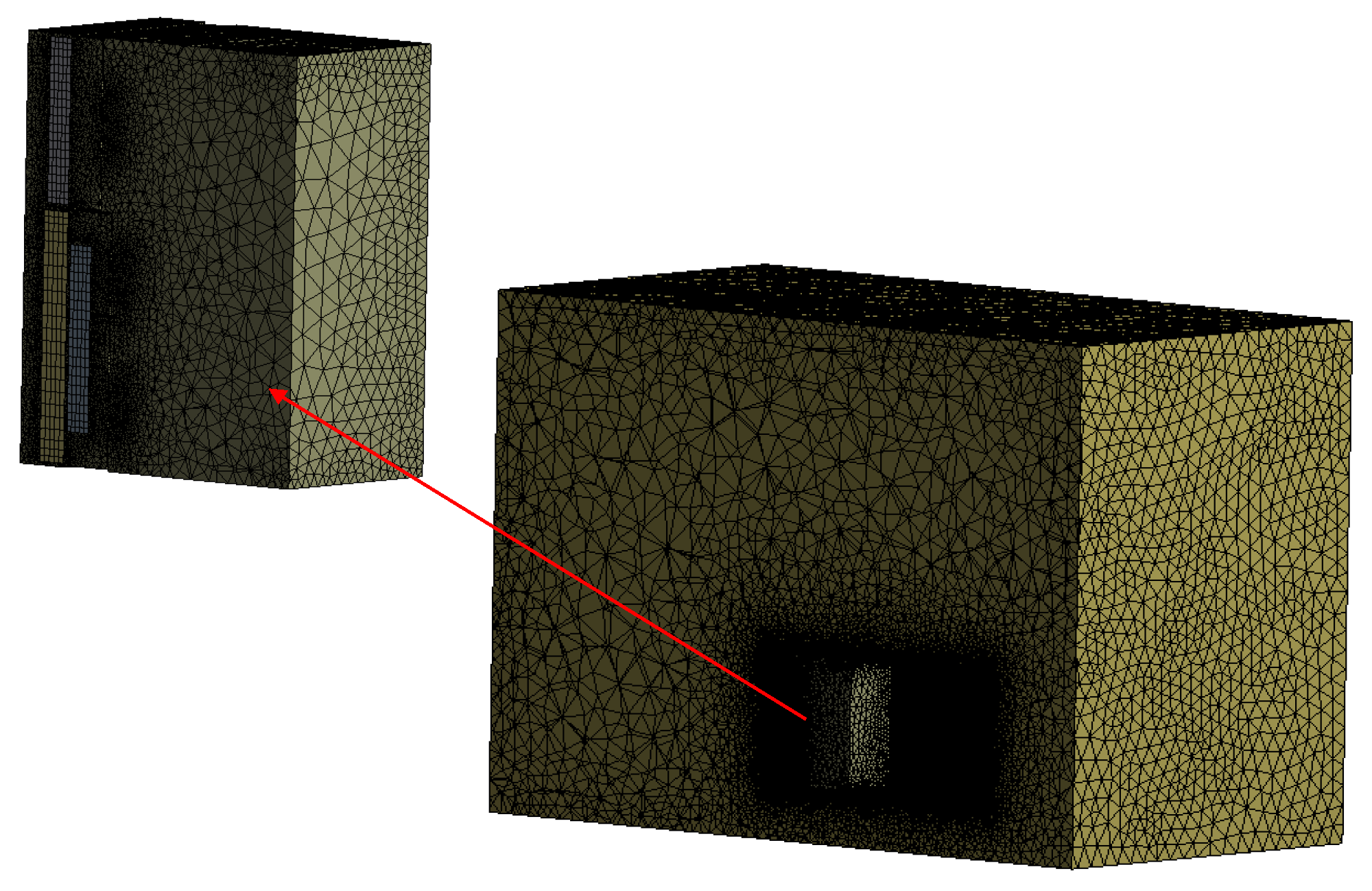
3.2. Mesh Generation

For rotating air domains, tetrahedral mesh is used here as the surfaces of fan blades are irregular and need special mesh density. For radiators, the structural grid is used as the structures of radiators are regular. Here we use porous medium to simulate the four radiators [21,22] because the computer cannot suffer such large meshes if the real structures of radiators are used. For the porous model, its porosity and resistance coefficient are two important diameters. The porosity can be gained by plane map calculation according to CAD drawing of radiator manufacturers. The resistance coefficient can be calculated by the following formula:
K Q = ( Δ p / Δ x ) / c 2
where Δ p is the static pressure difference of the radiator, Δ x is the radiator wall thickness, c is the average speed of cooling air. All radiator diameters are shown in Table 1.
The structural grid is also used for inlets, outlets and other regions. Finally, the meshed model is shown in Figure 3.

3.3. Boundary Conditions Settlement

For the rotating air domain, the rotating air is set to be a fluid model and seven fans are set to be different domains rotating with different axes. In addition, the boundary of the interfaces between air and fan surfaces are set to be wall conditions.
As the power of heat conduction in the engine cover wall is small compared with radiators and system maximum temperature is only up to about 100 °C, the system heat conduction is ignored as well as its thermal radiation. Hence, for another air domain, the boundary of surfaces is set to be the adiabatic wall condition, with an opening boundary in air inlet and outlet, as well as a computational domain.
The turbulence model adopts K-ε one, as a high Re number condition K-ε flow model can take a rotating effect into consideration and shows a higher computational accuracy in strong rotate flow [23]. The simulation employs the Thermal Energy model. The solver uses Segregated/Implicit type, and adopts the SIMPLE algorithm to solve the coupled analyses of speed and pressure. The type of discrete equation adopts the second order upwind scheme.
The cooling air is set with pressure of 101 kPa, and density of 1.293 kg/m3. As the speed of cooling air is much lower than sound speed and it is a small-Ma fluid situation, the cooling air is assumed to be incompressible and ideal gas.
The grid independence is also studied to ensure the accuracy of simulation. As shown in Figure 4, with the growth of grid number, the temperatures of inlet and outlet in the engine radiator are changing. Until the number of grids increases to 7 million, the curves of supervised temperatures become smooth and steady. This is the same as that of the torque convertor radiator. In overall consideration of hardware equipment, calculating time and simulation error, the total number of grids is set to be about 8.86 million in the following simulations.

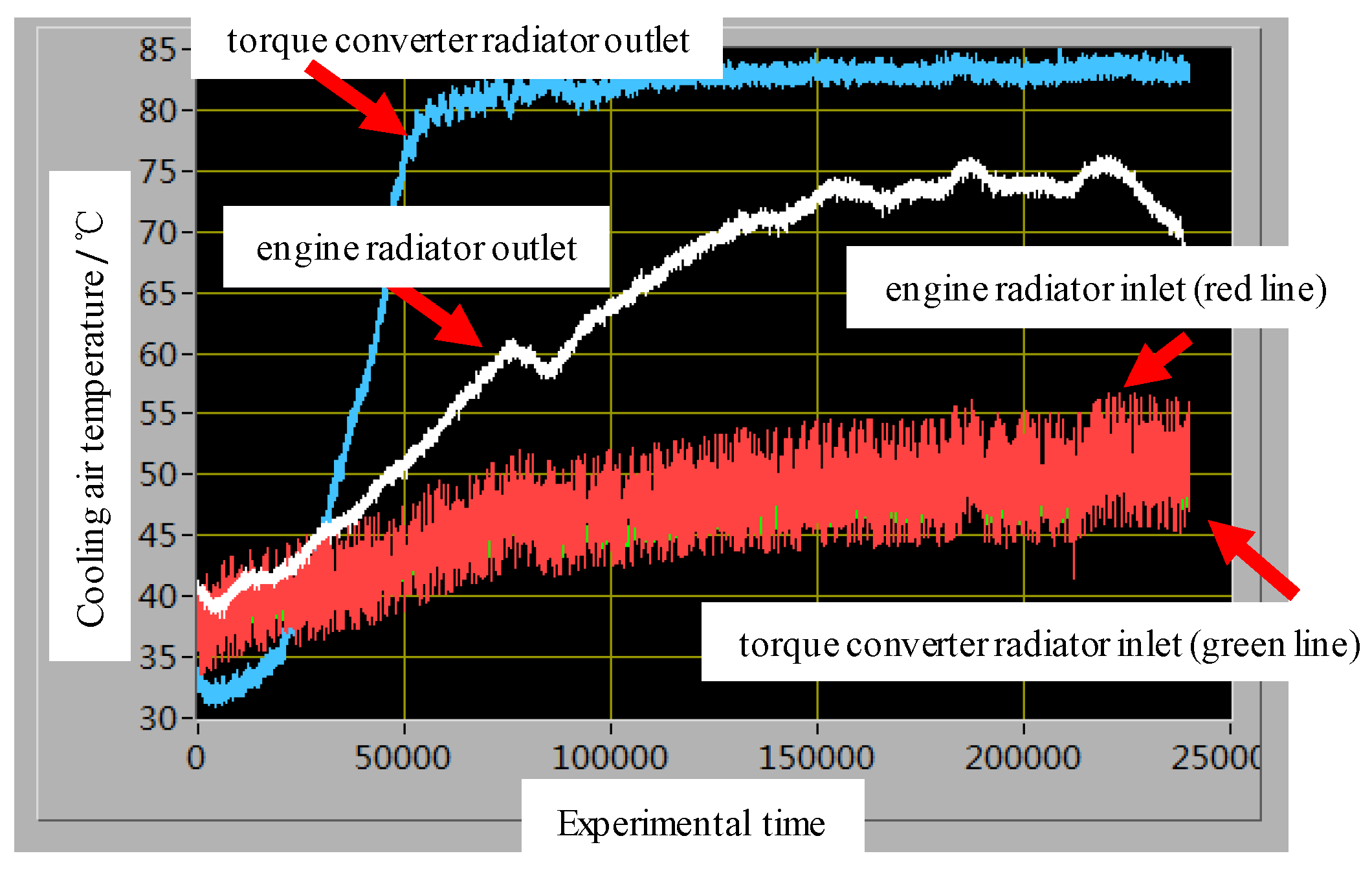
4. Experimental Comparison

The outdoor experiments were carried out in surroundings of 35 °C temperature and 67% humidity with a good sunshine, and lasted for hours after temperature balance. The temperature was measured by the k-type sheathed thermocouples with an accuracy of 1.5 K. The coolant flow volume is measured by the turbine flowmeters with an accuracy of 1%. The cooling air flow volume is measured by the industrial air velocity transmitter of Omega FMA1003A-MA with an accuracy of 1.5%. All the experimental data are collected by the testing modules of Yanhua Company.
As shown in Figure 5, the working conditions were the same as those of the simulation. The air temperature of the torque converter radiator inlet was almost the same as that of the engine radiator so that the two curves overlapped, and it was seen in the figure that the green line is covered by the red line. The cooling air temperature of the engine radiator outlet was kept at about 75 °C, lower than the temperature of 80–90 °C using one fan in previous systems. Table 2 shows the comparisons of simulation and experimental results. The relative errors can be induced by measuring the accuracy of the experimental apparatus, computation accuracy of the simulation model, environment situation inconsistent with simulation assumption more or less, and so on. However, it is still clearly seen that the two results agree well, which indicates that our model and simulation are reliable and effective. Hence, the next part of the article will demonstrate more simulation details regarding the heat transfer and flow characteristics of this new cooling system.

5. Discussions of Simulation Analyses

This part of the article focuses on numerical simulations on the flow and temperature fields of the new cooling system in the engine compartment for a thorough understanding, in the hope of providing results that are helpful in future structure improvements and system designs.

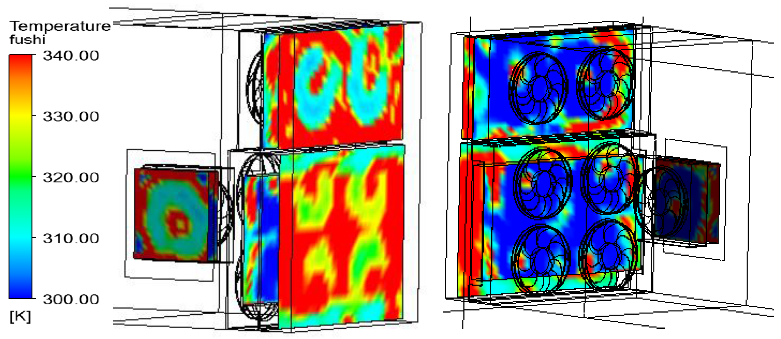
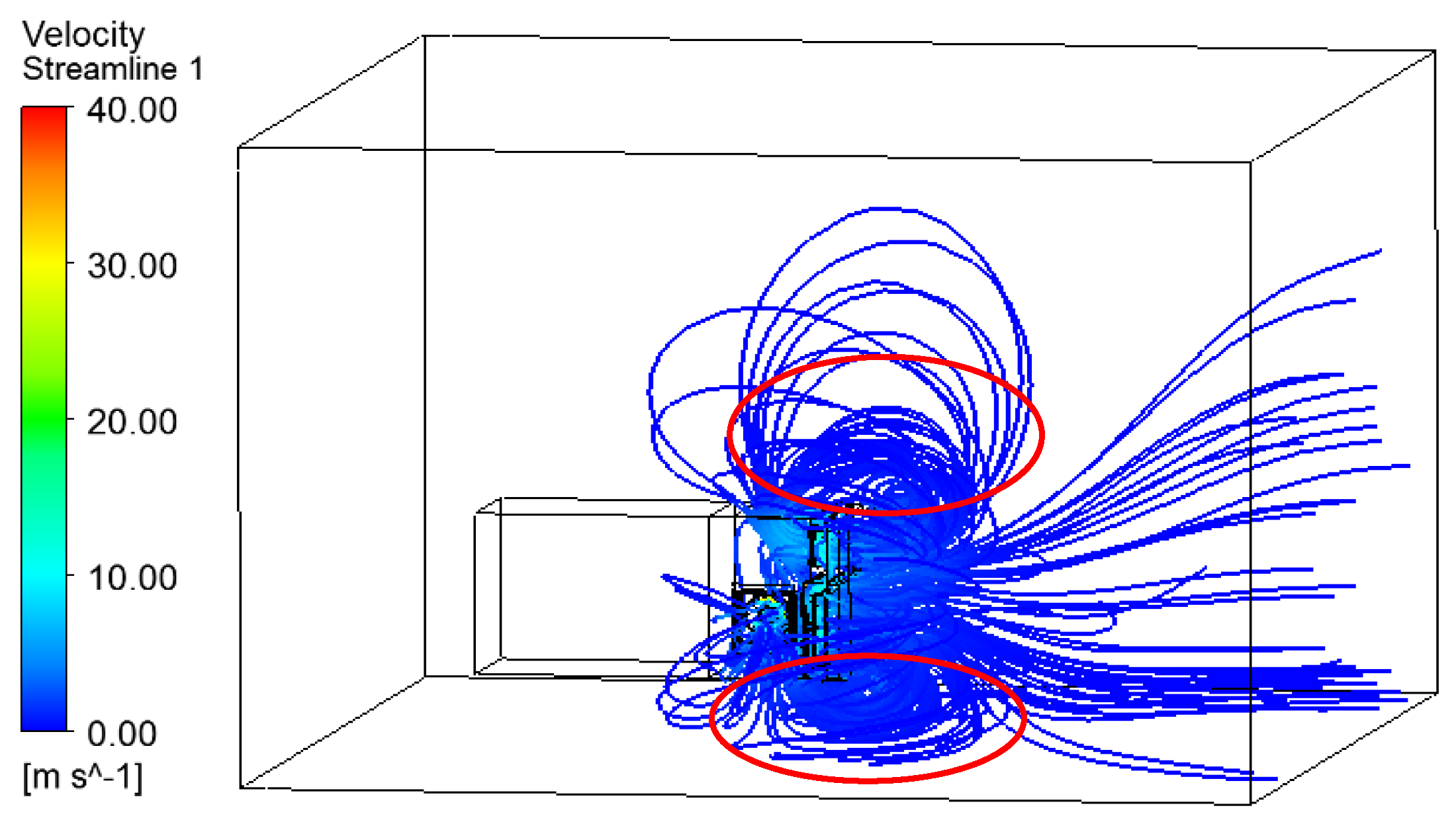
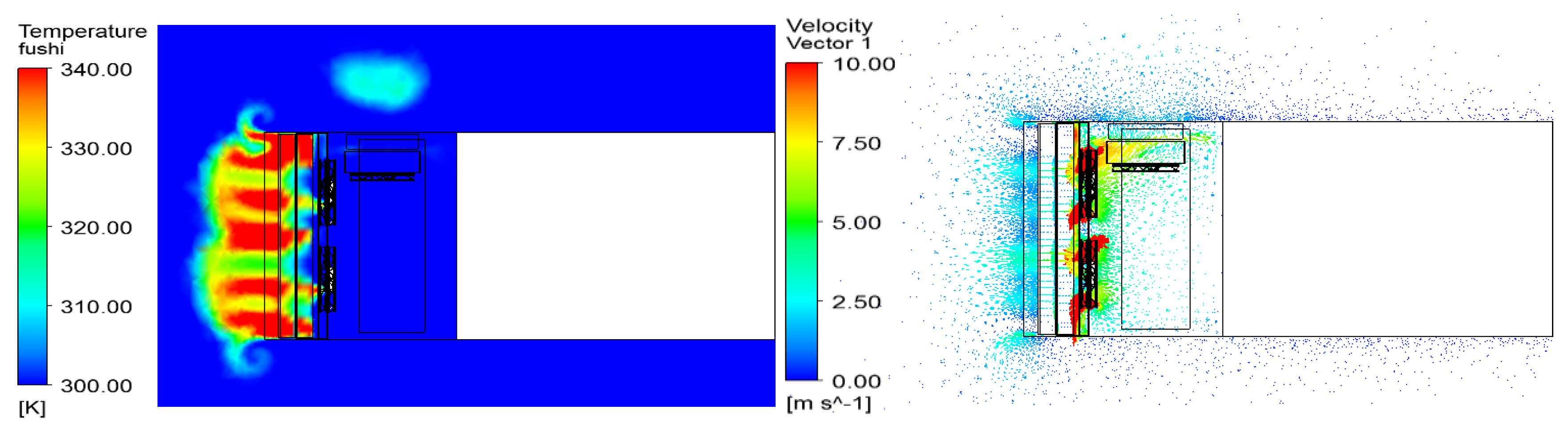
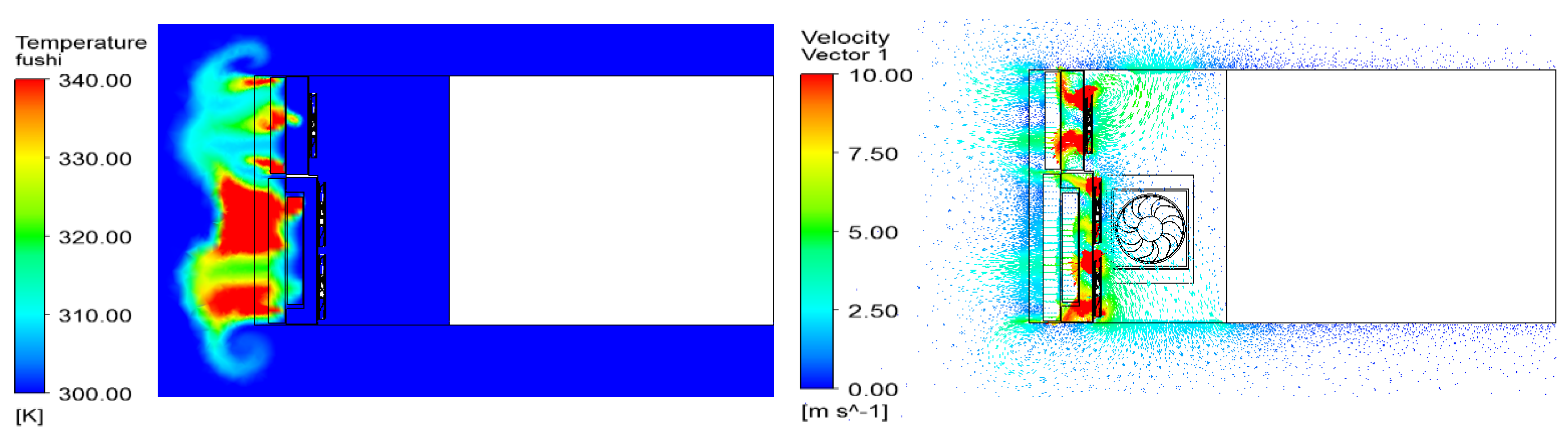
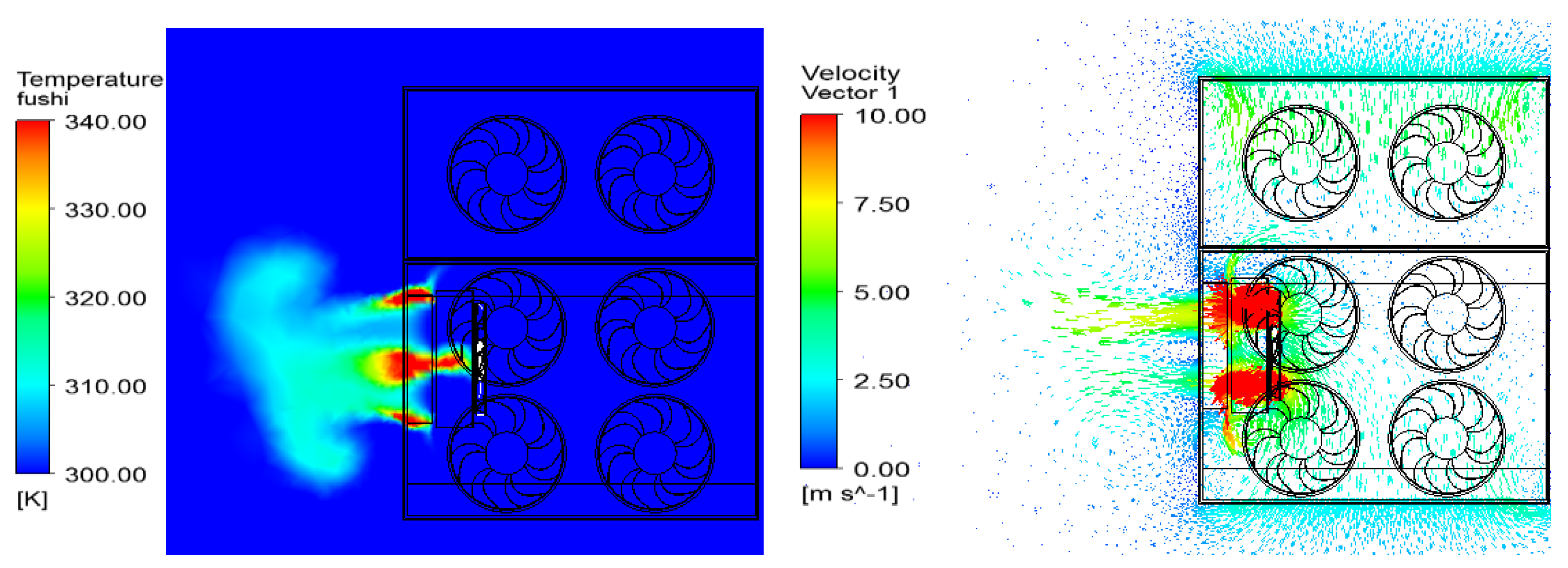
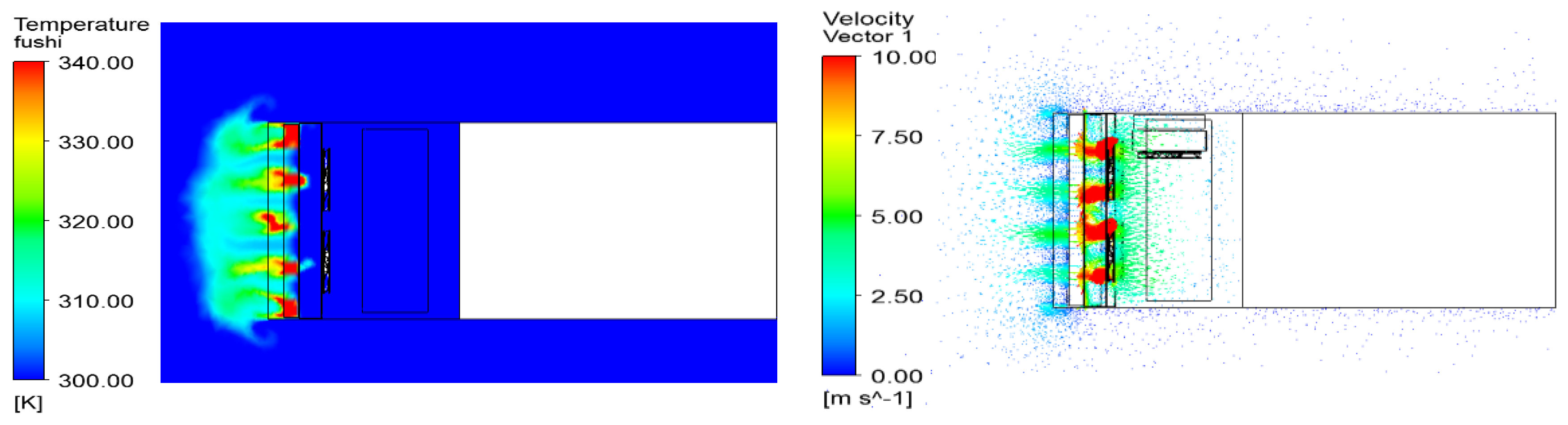
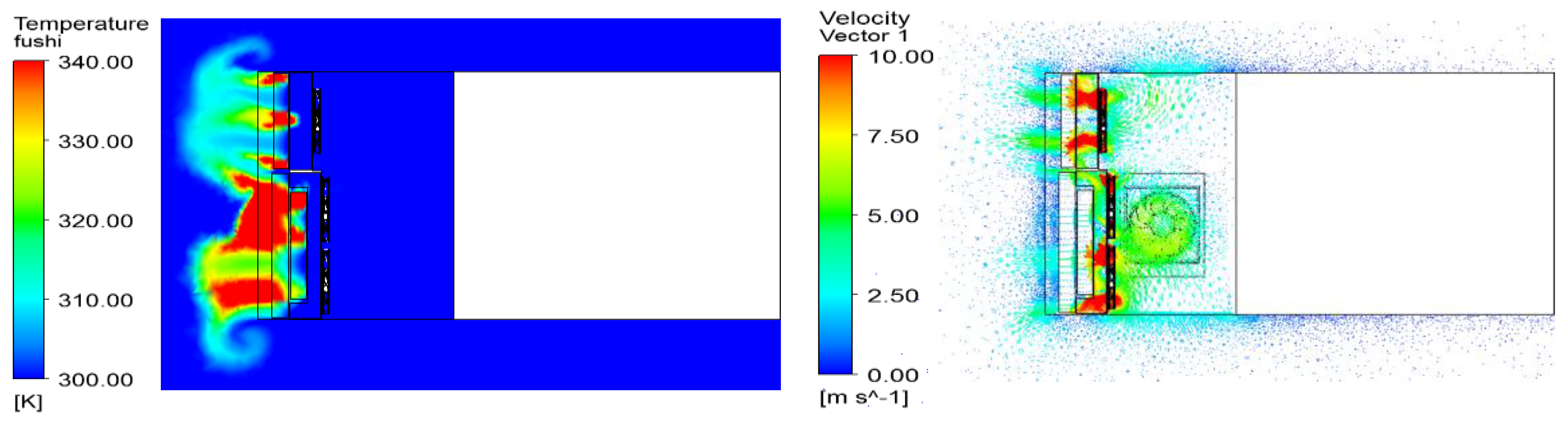
5.1. Temperature and Flow Distributions of the Cooling Regions

Figure 6 shows the temperature distributions in the inlet and outlet sections of the four radiators. In the air inlet section, the averaged air temperature is almost uniform at about 323 K. In the air outlet section, the temperature in the regions covered by cooling fans is obviously lower than that out of the fan action regions (red area). The average temperature of the torque converter radiator is lower than that of the engine radiator, because in the lower part the thermal load of 101 kW is about twice as large as that of the torque converter radiator, although there are four fans directly working for the engine radiator. The hydraulic oil radiator achieves a good cooling mark as it is relatively independent and not greatly influenced by the other fan groups.
Figure 7 shows the flow field of the whole air region. The velocity of most cooling air is about 5 m/s, except that on the edge of the fans, which could be up to 40 m/s. There are two positions needing additional attentions, circled by red lines in the figure. One is the top air inlet. Since the top air inlet is opened near to where the front outlet grids are, the air backflow problem is still occurring in this region and it will increase the intake air temperature. The same phenomenon also appears in the bottom air inlet, and this is even more serious because of the ground effect. Therefore, one suggestion in future modifications is that the location of the top air inlet can be slightly farther away from the front outlet grids to reduce air mixing and backflow in this area. Another suggestion is that the section of the bottom air inlet can be made smaller so that the cooling air can be sucked into the region from the upper air inlet as much as possible for better heat dissipation.

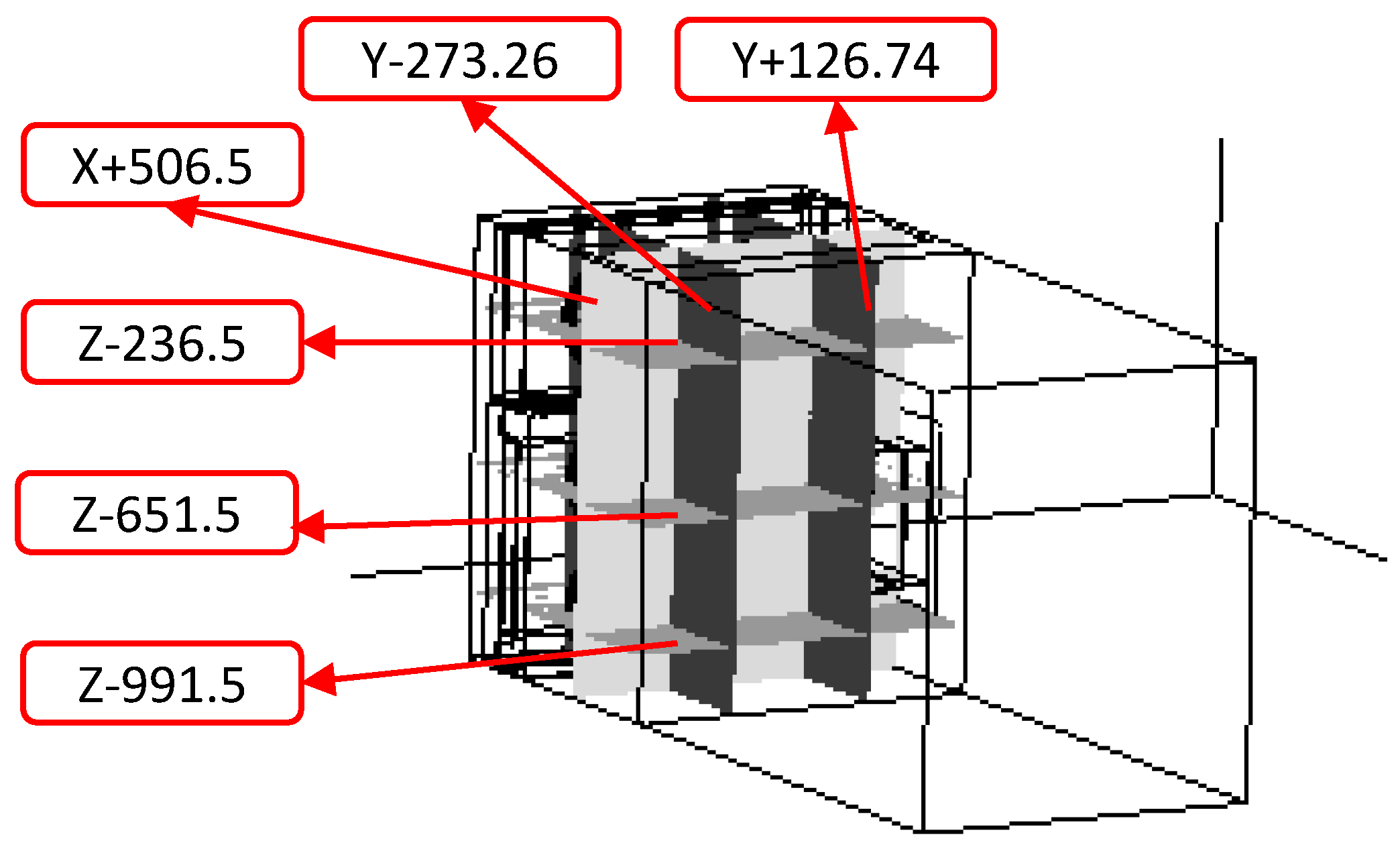
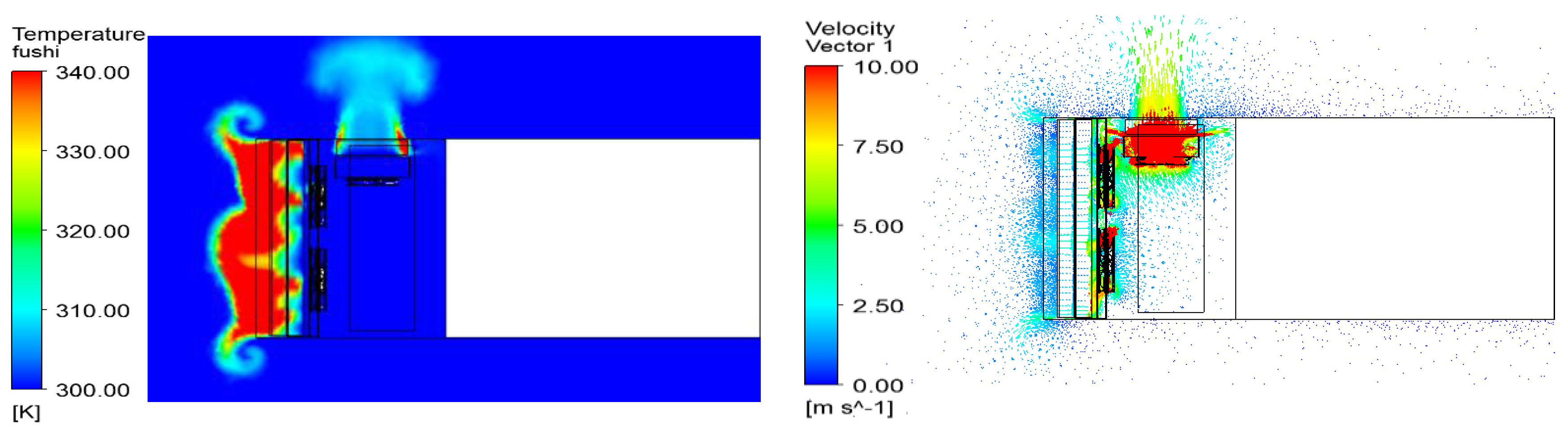
5.2. Thermal Analyses of Six Cross-Sections

In order to obtain more details of heat transfer characteristics in the fan groups, temperature distributions of six cross-sections are added into the simulation analyses, as shown in Figure 8. Cross-sections Z − 236.5, Z − 651.5, and Z − 991.5 are parallel to the ceiling of the engine compartment and through the central axes of upper, middle and lower fans, named as Planes 1–3, respectively. Cross-sections Y − 273.26, Y + 126.74 are parallel to the side plane of the engine compartment and also through the central axes, named as Planes 4–5, respectively. Cross-section X + 506.5 is parallel to the front plane of the engine compartment and through the front outlet grids, named as Plane 6. The six cross-sections are used to study the local temperature distributions of different positions and the changing trends of the temperature field in different directions.
Figure 9 shows the temperature field of Plane 1 (Cross-section Z − 236.5). The red region represents the high temperature area in the torque converter radiator, corresponding to the fan hub areas without flowing air and the places not covered by the fans. However, the temperatures immediately become lower after air leaves the radiator, as is clearly seen in the figure. From Figure 9 it can also be seen that, with an isolation board, hot air is prevented from flowing into the engine region and the temperature in this region is almost kept at about 30 °C.
Figure 10 shows the temperature field of Plane 2 (Cross-section Z − 651.5). The average temperature of this region is higher than that of Plane 1 because cooling air arrives here last and there are two heat sources, the intercooler and the engine radiator. In the fan hub areas, heat is stacked here, whereas in the other areas heat is blown away by the strong wind. Meanwhile, the two fans are interacting and coupling in their edges so that temperature distribution is like a wave. An interesting phenomenon of energy convolution appears in each edge of the fan group because of the air backflow explained above in Figure 6. The temperature field of Plane 3 (Cross-section Z − 991.5), shown in Figure 11, is almost the same as that of Plane 2, but the average temperature of Plane 3 is lower than that of Plane 2. This is because the air inlet grids are opened at the bottom of the engine compartment and air is sucked into the lower fan groups in priority, so that the bottom fans enjoy more and cooler intake air used in heat dissipation.
The temperature distributions of Plane 4 (Cross-section Y − 273.26), Plane 5 (Cross-section Y + 126.74), and Plane 6 (Cross-section X + 506.5) are, respectively, shown in Figure 12, Figure 13 and Figure 14. As the distributions are similar to each other, and quite close to those in Planes 1–3, they will no longer be explained in detail here. The differences of the side fan group shown in Figure 14 are: (i) that there is no fan coupling activities due to only one fan set here; and (ii) its rotating speed is 3200 rpm in order to ensure enough air flow volume for the hydraulic oil radiator.

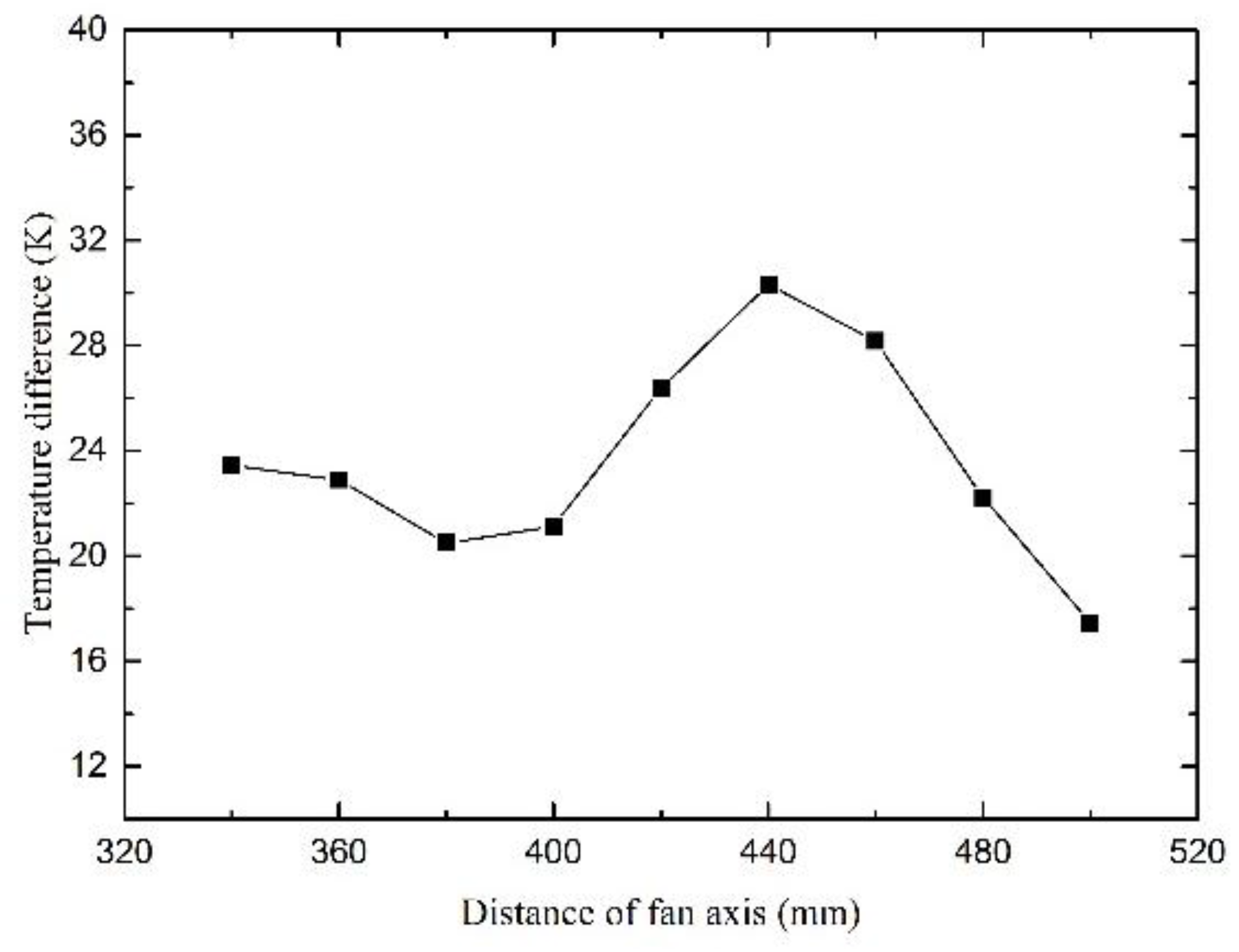
5.3. The Effect of Different Axes Distances on Temperature Distribution

As shown in Figure 6 and Figure 10, airflow interaction exists in the spaces between the two fans when the present axes distance is 400 mm. This phenomenon will aggravate flow turbulence and energy waste and is detrimental for system cooling. In order to decrease mixing airflow at the junctions of fans, the central axes distance of two fans will be changed to study its effect on temperature distribution, which is shown in Figure 15. Taking the upper fan group, for instance, the curve of the differences of average temperature between outlet and inlet sections versus distances of fan axes is shown in Figure 16. With the axes distance changing from 340 to 500 mm, the temperature difference firstly stays at about 22 K, then increases to a maximum value of 30 K at the distance of 440 mm. Afterwards, the temperature difference begins to decrease with increasing distance and drops down to 17.45 K at the distance of 500 mm. The reason for this is that if the distance of two fans is too long, the radiators will not be covered fully by the fans, especially in the spaces between the two fans; but if they are too close, the airflow interaction will strengthen at the edges of fans. As a result, both situations will lead to poor cooling effects and temperature increases. Hence, there is a best distance of the fan axes. In this cooling system, its optimal distance is 440 mm and the interval of the two fans is 120 mm.

5.4. The Effect of Thermal Baffles on Temperature Distribution

Although there is an optimal distance of the fan axes, it is limited to the engine compartment space. In this case, the best distance is 440 mm, but it will enlarge the cooling cabin size. Therefore, thermal baffles are adopted according to the previous research. There are three baffles set to separate the upper and lower fan groups into six individuals, which is shown in Figure 15. This can decrease air interaction and flow turbulence to a significant extent. As shown in Table 3, with baffle changes, the average temperature differences of the outlet and inlet sections in all radiators increase, especially for the engine radiator, which is up to 14 K. It can be seen that the effect of the thermal baffle is obvious and this will be the main improvement in our new machinery.

6. Conclusions

This paper employs a new cooling system with multiple fans and an independent cooling region. According to power flow and performance requirements, seven fans are divided into four groups: two of them in the upper part for cooling the torque converter radiator, four in the lower part for the engine radiator and intercooler, and the last one for the hydraulic oil radiator in the side. The independent cooling region is segregated from the engine region by a thermal baffle in order to avoid heat flowing into the engine region. The cooling air temperature of the engine radiator outlet was kept at about 75 °C, lower than that of previous systems, which were always about 80–90 °C. The experiment also validates the accuracy of the simulation. After validation, the simulation then analyzes heat transfer and flow characteristics of the cooling system changing with different cross-sections in different axis directions, as well as different distances of the fan central axis. It is found that there is a best distance of the fan axis and in this cooling system this best distance is 440 mm. Finally, thermal baffles are set between fan groups and it is found that this benefits the cooling effect greatly: the average temperature differences of outlet and inlet sections in all radiators increased, especially in the engine radiator, up to 14 K. The research realizes a multi-fan scheme with an independent cooling region in a wheel loader, which is a new, but high-efficiency, cooling system and will lead to a change of various configurations and system designs in future engine compartments.

Acknowledgments

The presented work was supported by the President Foundation, Great Scientific and Technological Foundation of Fujian Province of China (Grant No. 2016HZ0001-9).

Author Contributions

The authors contributed equally to this work.

Conflicts of Interest

The authors declare no conflict of interest.

References

  1. Zhang, H.; Li, J. Design Handle Book of Vehicle Cooling System; National Defense Industry Press: Beijing, China, 1984. (In Chinese) [Google Scholar]
  2. Tan, X. Hydraulic excavator of LZ600-1 load type in Komatsu. Constr. Mach. 2014, 11, 73. (In Chinese) [Google Scholar]
  3. Caterpillar. Smart steel era, innovation construction productivity, efficiency and security. Constr. Mach. 2016, 1–4. (In Chinese) [Google Scholar]
  4. Mahmound, K.G.; Loibner, E.; Wiesler, B. Simulation-based vehicle thermal management system concept and methodology. SAE Tech. Paper 2003. [Google Scholar] [CrossRef]
  5. Li, K.N.; Zhou, W.; Guo, C. Experiment and simulation of the performance of automotive radiator. Mech. Sci. Technol. Aerosp. Eng. 2014, 33, 1079–1082. [Google Scholar]
  6. Torregrosa, A. Assessment of the influence of different cooling system configurations on engine warm-up, emissions and fuel consumption. Int. J. Automot. Technol. 2008, 9, 447–458. [Google Scholar] [CrossRef]
  7. Tong, Z.M.; Zhang, Y.F.; Chen, D. Research on the structure optimization of automobile radiators. Energy Res. Inf. 2014, 30, 108–112. [Google Scholar]
  8. Gao, J.; He, S. Overview of cooling fan research in construction machinery. Constr. Mach. 2007, 38, 33–37. (In Chinese) [Google Scholar]
  9. Allen, D.J.; Lasecki, M.P. Thermal management evolution and controlled coolant flow. SAE Tech. Paper 2001. [Google Scholar] [CrossRef]
  10. Kyoung, S.P.; Jong, P.W.; Hyung, S.H. Thermal flow analysis of vehicle engine cooling system. KSME Int. J. 2002, 16, 975–985. [Google Scholar]
  11. Robert, W.P.; Wsewolod, J.H.; Jeffrey, K. Thermal management for the 21st century—Improved thermal control and fuel economy in an army medium tactical vehicle. SAE Tech. Paper 2005. [CrossRef]
  12. Tannoury, E.; Khelladi, S.; Demory, B.; Henner, M.; Bakir, F. Influence of blade compactness and segmentation strategy on tonal noise prediction of an automotive engine cooling fan. Appl. Acoust. 2013, 74, 782–787. [Google Scholar] [CrossRef]
  13. Cho, H.; Jung, D.; Assanis, D.N. Control strategy of electric coolant pumps for fuel economy improvement. Int. J. Automot. Technol. 2005, 6, 269–275. [Google Scholar]
  14. Oh, K.; Kim, H.; Ko, K.; Kim, P.; Yi, K. Integrated wheel loader simulation model for improving performance and energy flow. Autom. Constr. 2015, 58, 129–143. [Google Scholar] [CrossRef]
  15. Stephens, T.; Cross, T. Fan and Heat Exchanger Flow Interactions. SAE Paper 2005. [Google Scholar] [CrossRef]
  16. Zhang, S.; Liu, Y. Double fans with each speed regulation used in tracked vehicle. Veh. Power Technol. 2007, 3, 11–13. (In Chinese) [Google Scholar]
  17. Fu, Q.; Zhu, T. Energy saving application of electronic fan on Higer Bus. Bus Coach Technol. Res. 2011, 6, 36–38. (In Chinese) [Google Scholar]
  18. Sun, Y.; Guo, Y. Research and design of fan driven system in meter combustion motor rail unit. Railw. Haul. Mot. Car 2013, 9, 25–27. (In Chinese) [Google Scholar]
  19. Zhang, Y.; Lu, G.; Yu, X.; Shi, H.; Zhang, W.; Xia, L. A study on the matching of multi-fan cooling module for commercial vehicles. Automot. Eng. 2014, 36, 552–556. (In Chinese) [Google Scholar]
  20. Cai, H.; Qian, Y.; Hou, L.; Wang, W.; Zhang, E.; Yang, W. Virtual design and analysis with multi-dimension coupling for construction machinery cooling system. Sci. China Technol. Sci. 2015, 58, 117–122. [Google Scholar] [CrossRef]
  21. Zhang, Y. Simulation Analysis and Experiment Research on Heat and Flow of Vehicle Radiator. Ph.D. Thesis, Zhejiang University, Hangzhou, China, 2006. [Google Scholar]
  22. Missirlis, D.; Donnerhack, S.; Seite, O.; Albanakis, C.; Sideridis, A. Numerical development of a heat transfer and pressure drop porosity model for a heat exchanger for aero engine applications. Appl. Therm. Eng. 2010, 30, 1341–1350. [Google Scholar] [CrossRef]
  23. Zhang, C.; Li, Y.; Zhang, Y. Numerical analysis for inner flow field in a centrifugal pump under maximum operating conditions. J. Mech. Electr. Eng. 2014, 31, 974–979. [Google Scholar]
Figure 1. 3-D model of engine compartment: (left) external view; (right) internal view.
Applsci 07 00231 g001
Figure 2. Schematic diagram of the cooling system.
Applsci 07 00231 g002
Figure 3. Meshed layout of engine compartment and whole air enclosing area.
Applsci 07 00231 g003
Figure 4. The study of grid independence.
Applsci 07 00231 g004
Figure 5. Cooling air temperature curve of different radiators by experiments.
Applsci 07 00231 g005
Figure 6. Temperature distributions of the outlet (left one) and inlet (right one) in the air cooling region.
Applsci 07 00231 g006
Figure 7. The entire flow field of air cooling region.
Applsci 07 00231 g007
Figure 8. Six cross-sections set in the cooling region.
Applsci 07 00231 g008
Figure 9. Temperature distribution (left) and velocity distribution (right) of Plane 1.
Applsci 07 00231 g009
Figure 10. Temperature distribution (left) and velocity distribution (right) of Plane 2.
Applsci 07 00231 g010
Figure 11. Temperature distribution (left) and velocity distribution (right) of Plane 3.
Applsci 07 00231 g011
Figure 12. Temperature distribution (left) and velocity distribution (right) of Plane 4.
Applsci 07 00231 g012
Figure 13. Temperature distribution (left) and velocity distribution (right) of Plane 5.
Applsci 07 00231 g013
Figure 14. Temperature distribution (left) and velocity distribution (right) of Plane 6.
Applsci 07 00231 g014
Figure 15. Schematic diagram of the cooling system with different intervals of the fan axis and thermal baffles.
Applsci 07 00231 g015
Figure 16. Temperature difference of the outlet and inlet in the torque converter radiator versus the axis distance of two fans.
Applsci 07 00231 g016
Table 1. Characteristic diameters of different radiators.
Engine RadiatorIntercoolerTorque Converter RadiatorHydraulic Oil Radiator
Heat dissipating capacity (kW)75265026
Cooling mediumEngine coolantcooling airoilHydraulic oil
size320 mm diameter, 400 m axis distance, 300 W power
Volume (m3)0.04300.02780.02960.00905
Heat source (kW/m3)1745.16897.981688.622874.52
porosity0.70.70.70.7
Resistance coefficient KQ35303025
Re number1.38 × 1051.38 × 1051.38 × 1051.84 × 105
Table 2. Experiment and simulation comparison on radiator temperature.
Experimental ValueSimulation ValueRelative Error
Temperature of torque converter radiator (K)inlet3213302.8%
outlet3563601.1%
Temperature of engine radiator (K)inlet323318−1.5%
outlet3483490.28%
Relative error = (simulation value − experimental value)/experimental value
Table 3. Temperature difference of outlet and inlet of all radiators versus thermal baffles.
Temperature Difference of Outlet and Inlet (K)Performance Improvement
Without baffle (A)With baffle (B)
Torque converter radiator21.1231.8350.71%
Engine radiator37.5951.0235.73%
Hydraulic oil radiator 18.7122.520.26%
Performance improvement = (B − A)/A

