
Active Vibration Suppression of a Motor-Driven Piezoelectric Smart Structure Using Adaptive Fuzzy Sliding Mode Control and Repetitive Control


Abstract
:1. Introduction
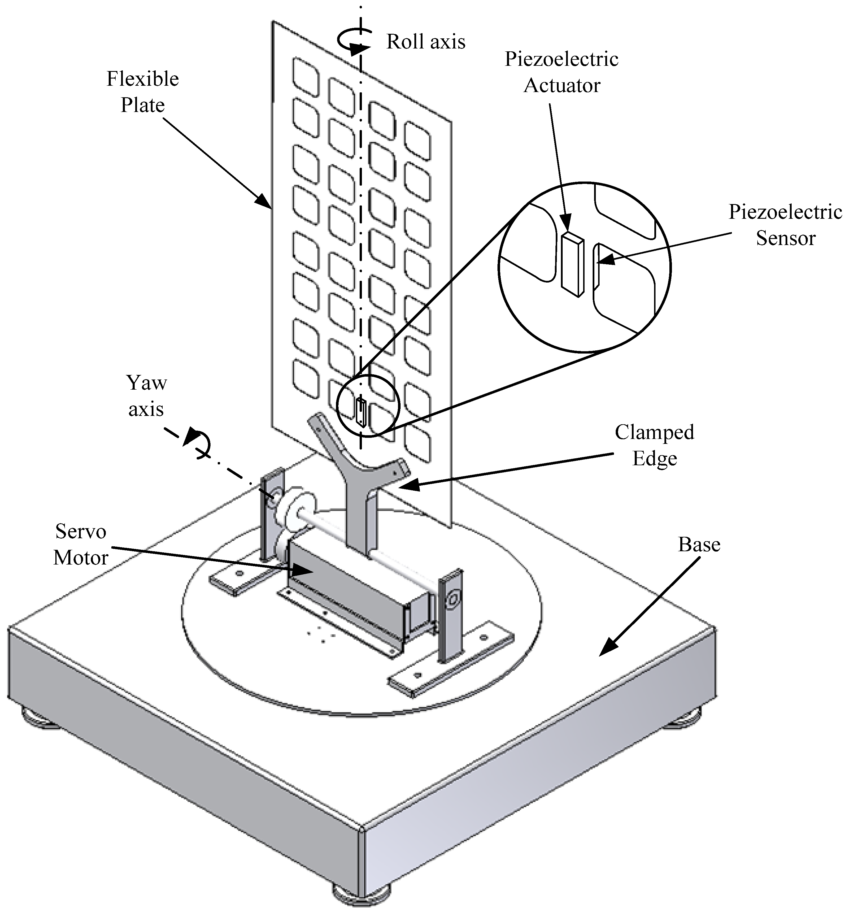
2. System Modeling
3. Controller Design for Active Vibration Suppression
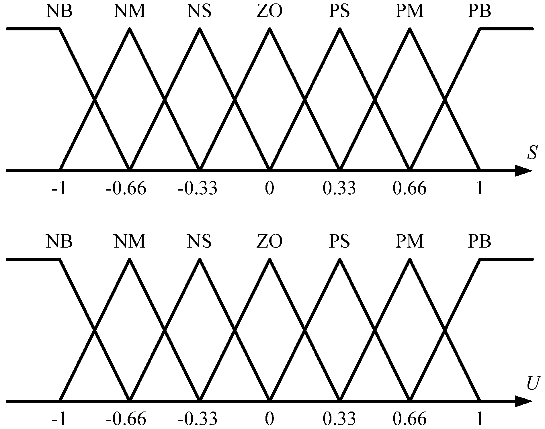
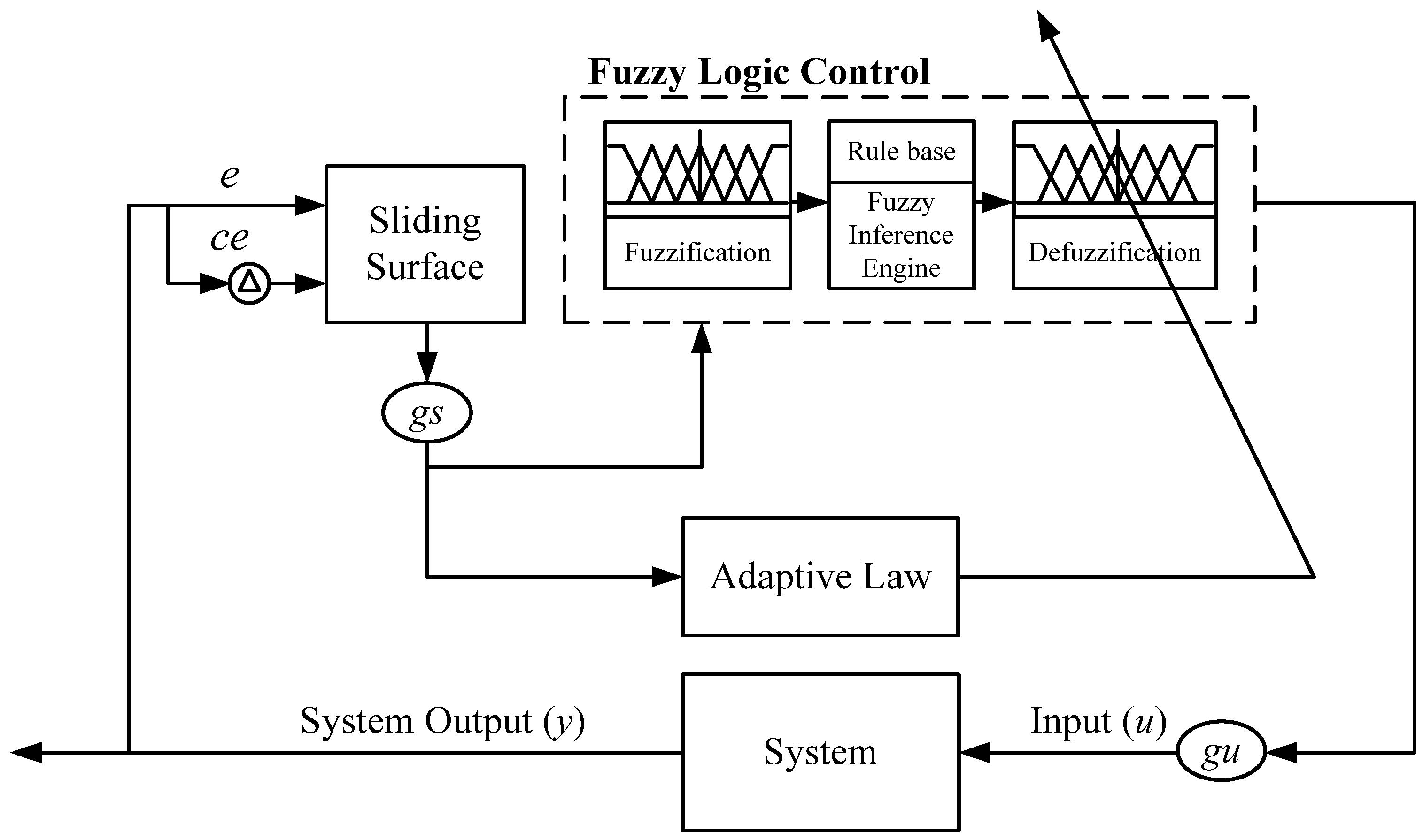
3.1. Adaptive Fuzzy Sliding Mode Control
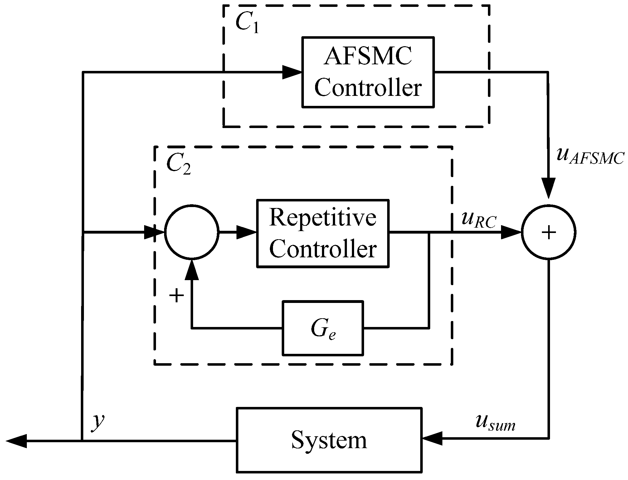
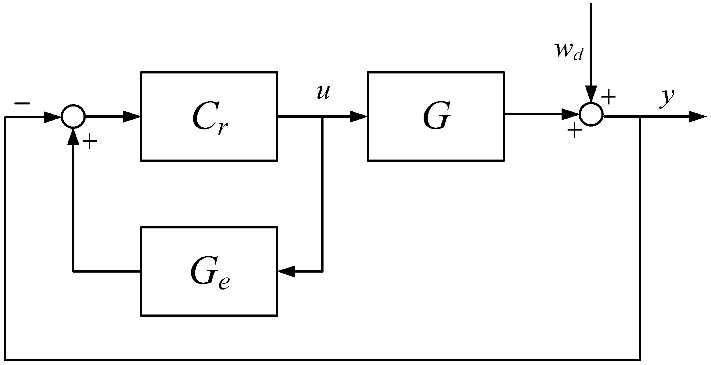
3.2. Hybrid Repetitive Control
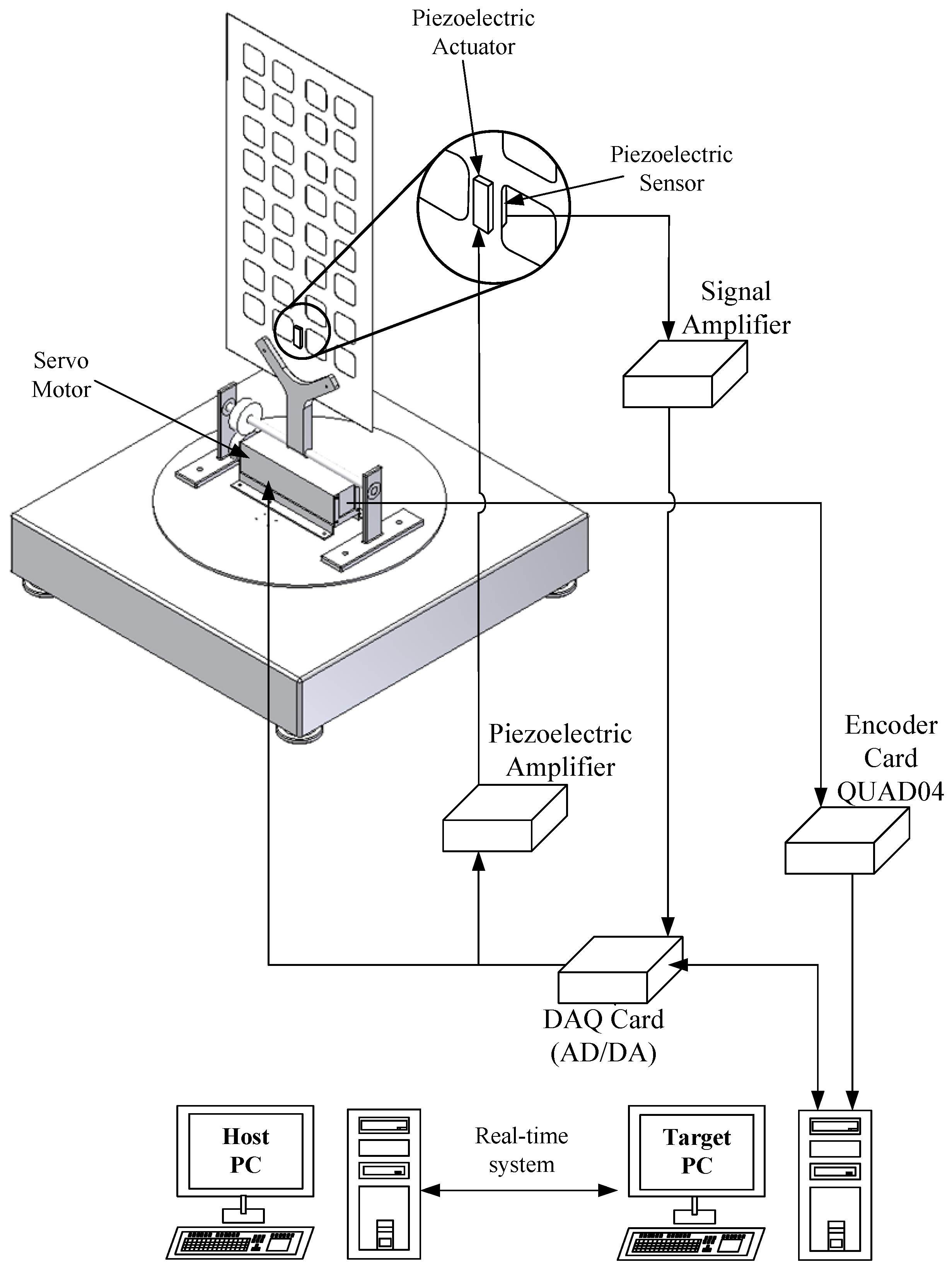
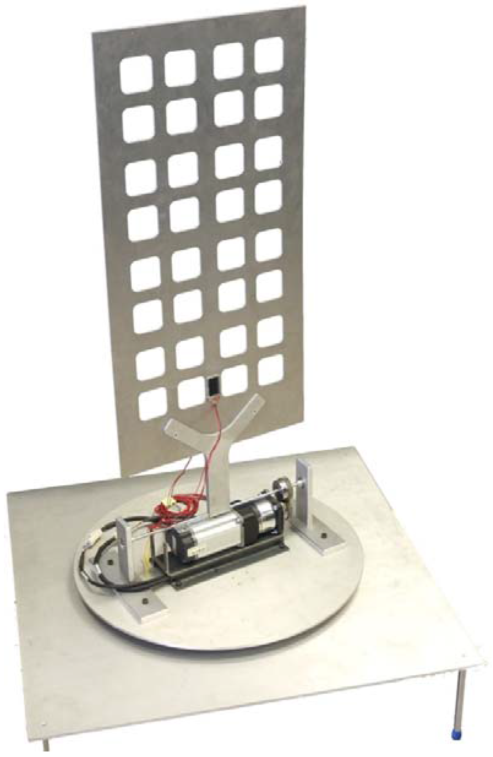
4. System Setup
5. Results and Discussion
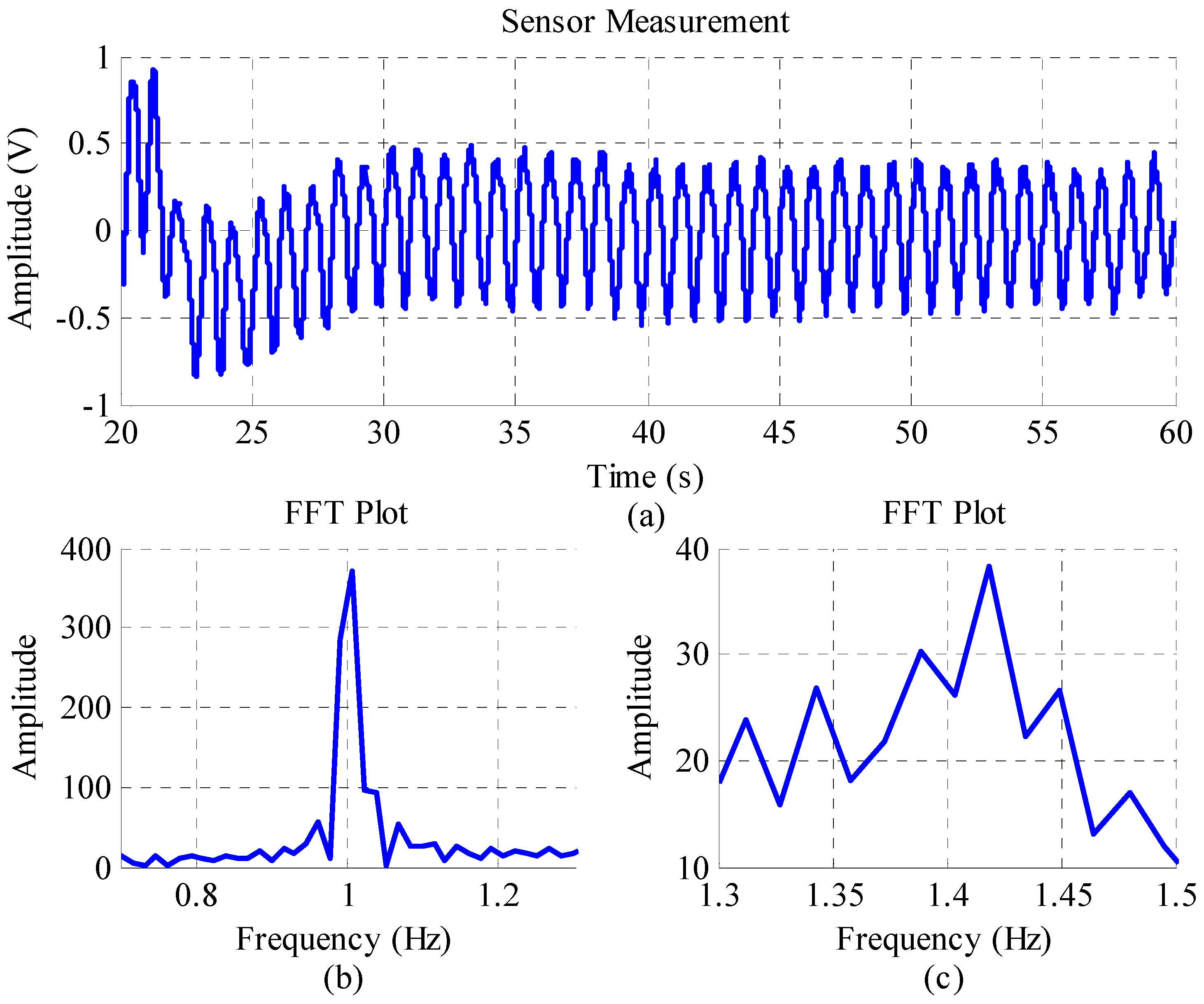
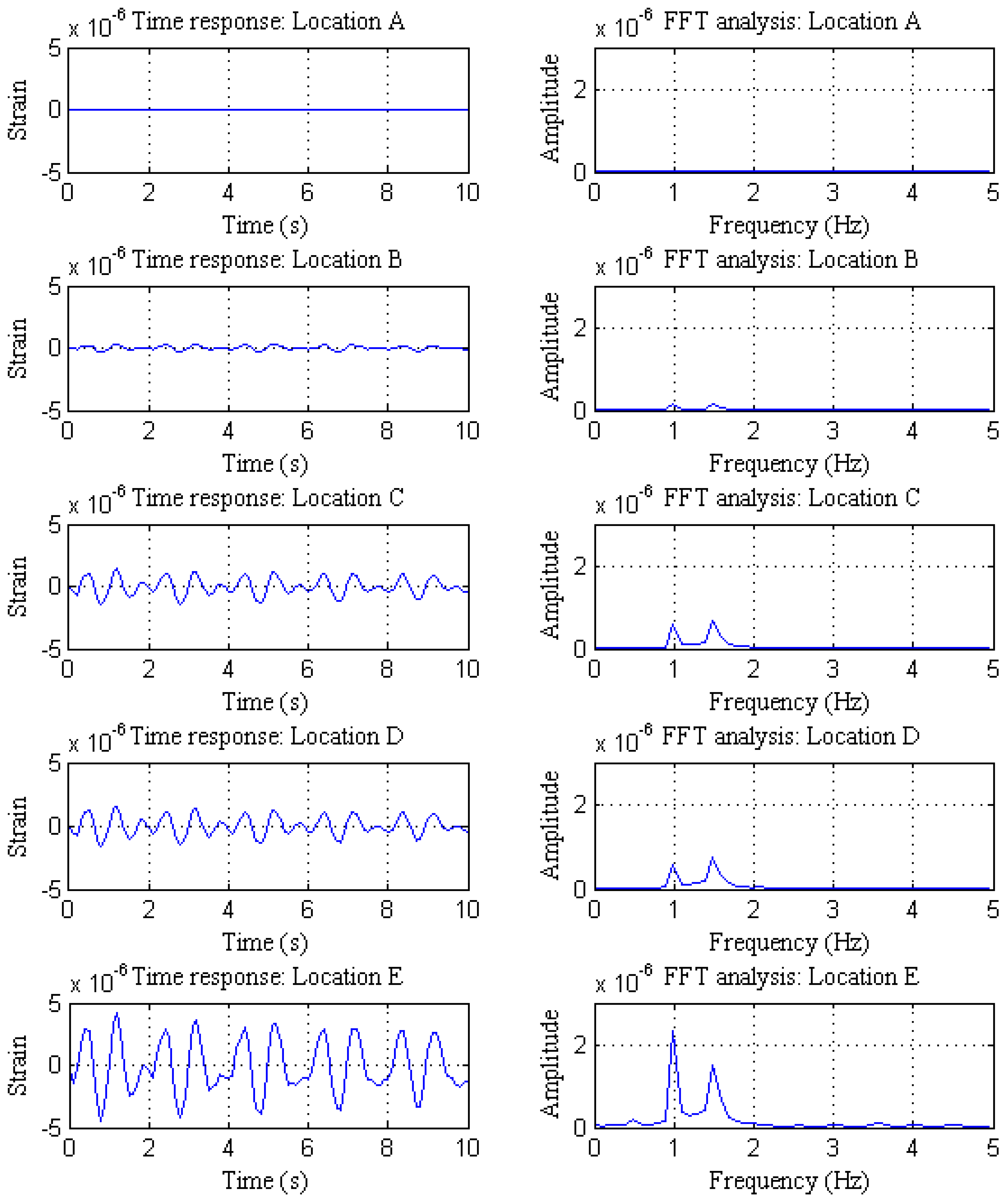
5.1. Motor Periodic Excitation
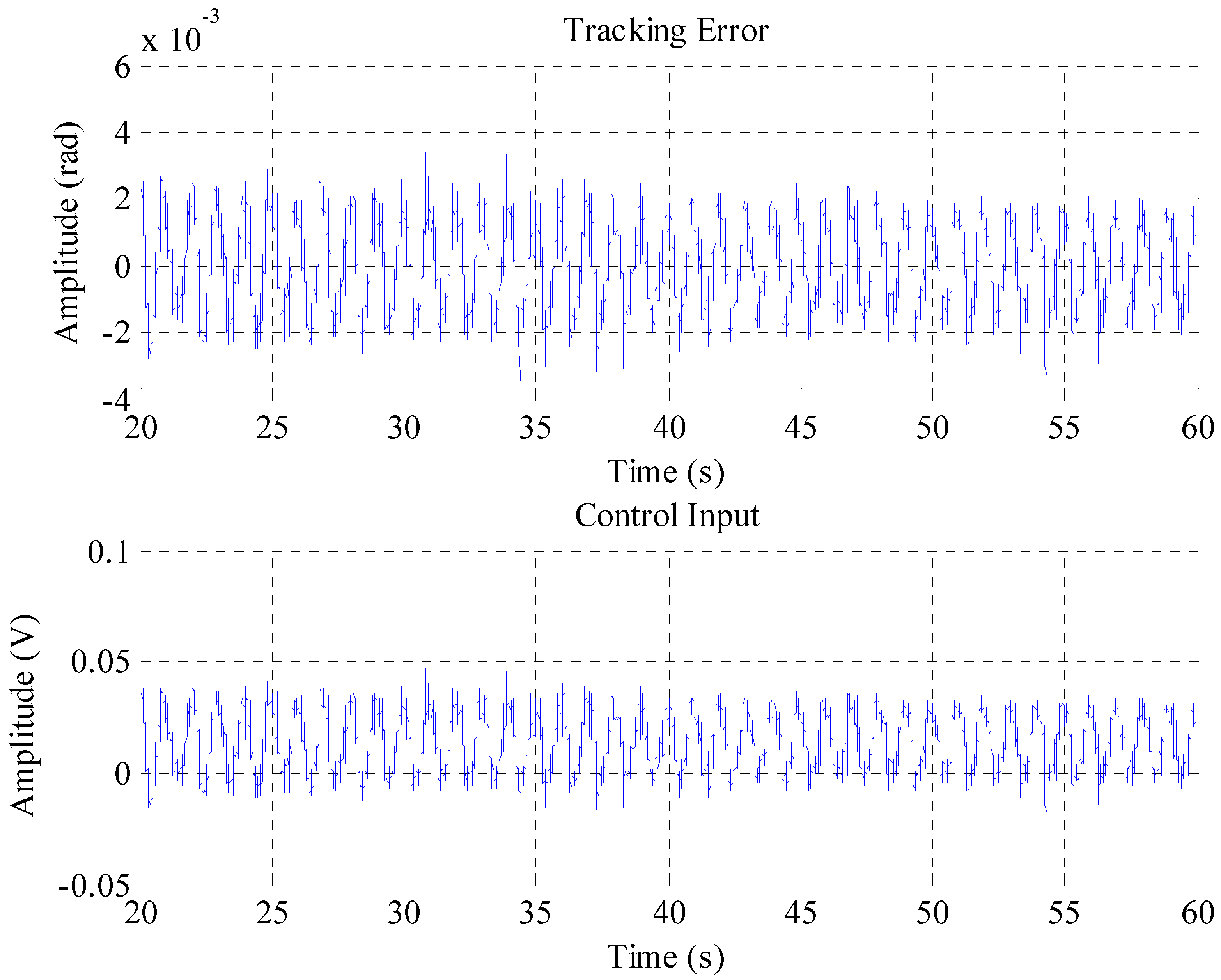
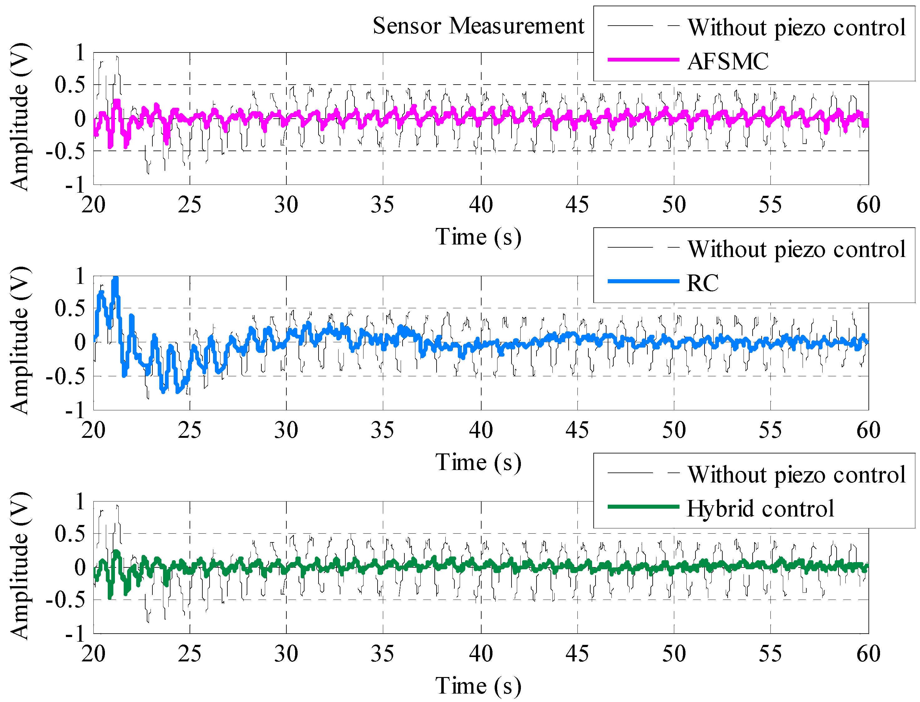
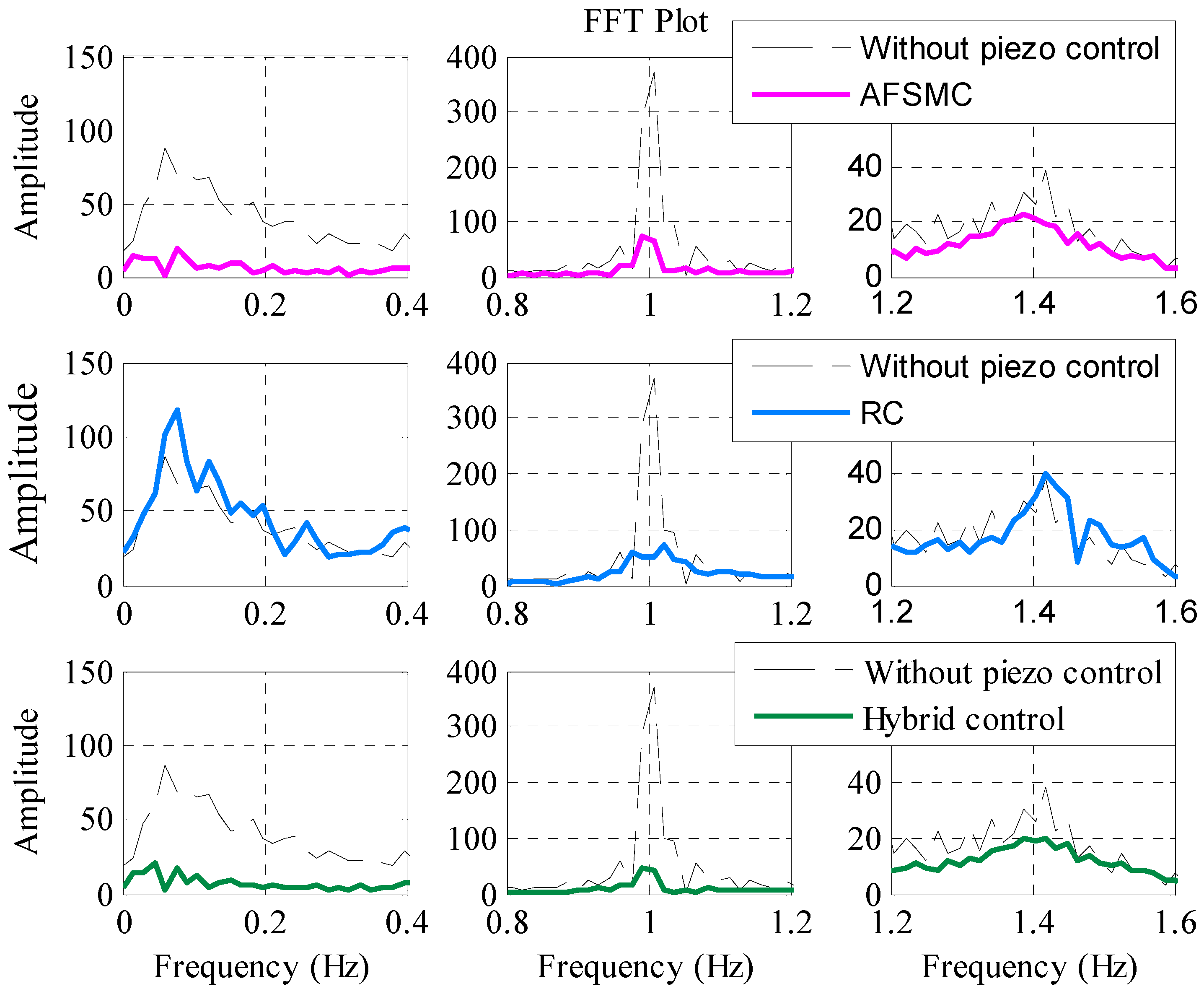
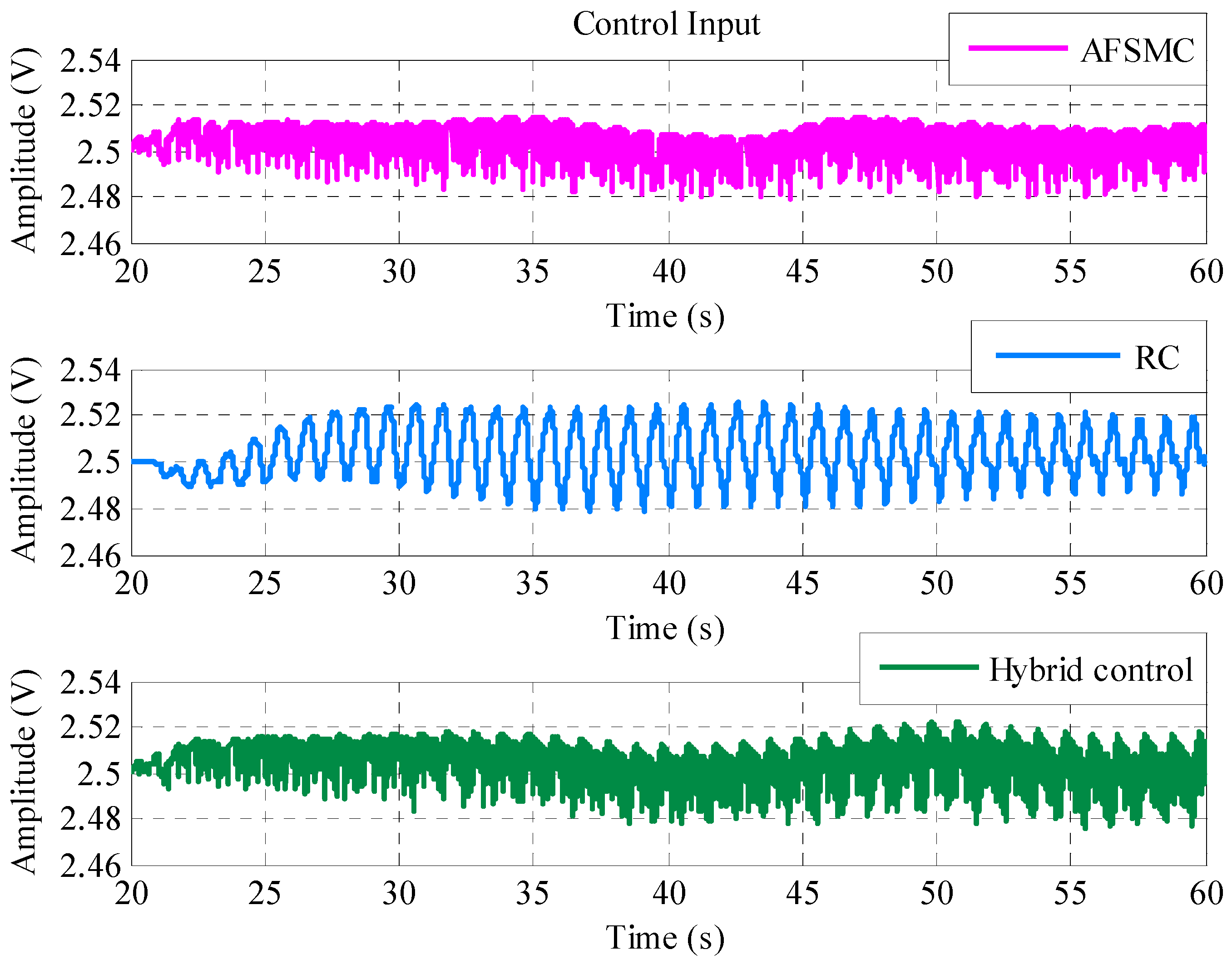
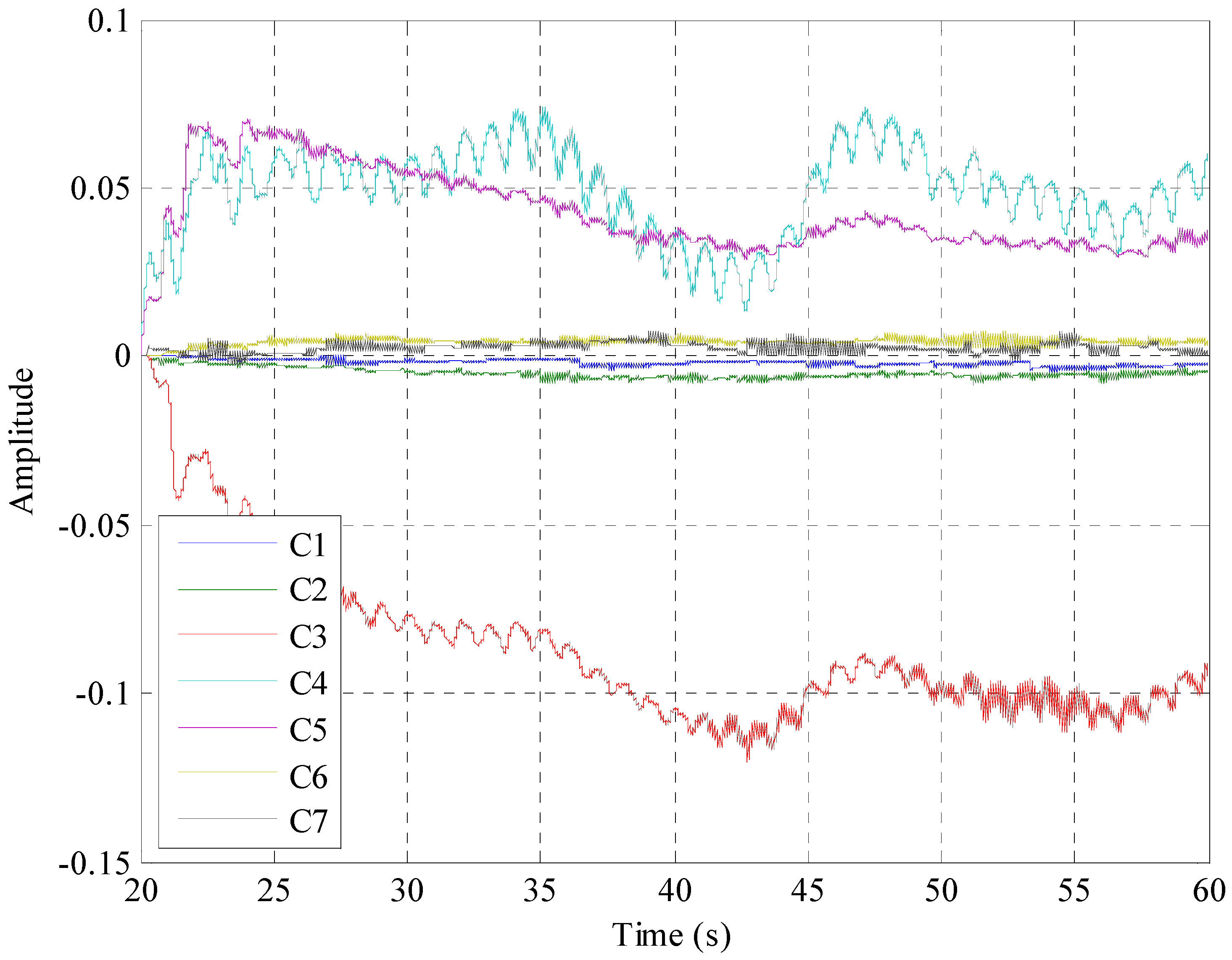
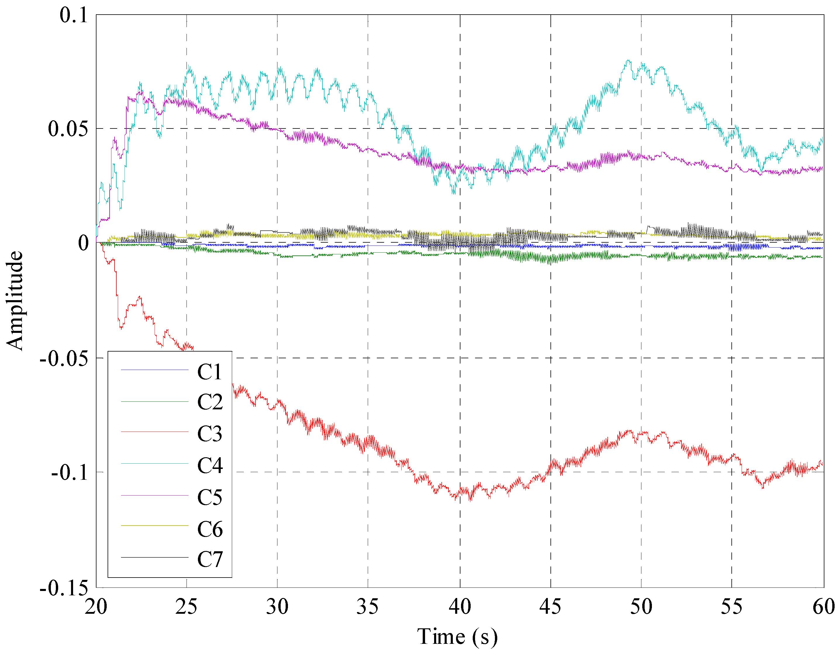
5.2. Piezoelectric Vibration Control
6. Conclusions
Acknowledgments
Author Contributions
Conflicts of Interest
References
- Iorga, L.; Baruh, H.; Ursu, I. A review of H∞ robust control of piezoelectric smart structures. Appl. Mech. Rev. 2008, 61, 1–15. [Google Scholar] [CrossRef]
- Lin, J. A vibration absorber of smart structures using adaptive networks in hierarchical fuzzy control. J. Sound Vib. 2005, 287, 683–705. [Google Scholar] [CrossRef]
- Kang, Y.K.; Park, H.C.; Hwang, W.; Han, K.S. Optimum placement of piezoelectric sensor/actuator for vibration control of laminate beams. AIAA J. 1996, 34, 1921–1926. [Google Scholar] [CrossRef]
- Tso, S.K.; Yang, T.W.; Xu, W.L.; Sun, Z.Q. Vibration control for a flexible-link robot arm with deflection feedback. Int. J. Nonlinear Mech. 2003, 38, 51–62. [Google Scholar] [CrossRef]
- Shan, J.; Liu, H.T.; Sun, D. Slewing and vibration control of a single-link flexible manipulator by positive position feedback (PPF). Mechatronics 2005, 15, 487–503. [Google Scholar] [CrossRef]
- Ahmad, M.A.; Ismail, R.R.; Ramli, M.S.; Zawawi, M.A.; Hambali, N.; Ghani, N.M.A. Vibration control of flexible joint manipulator using input shaping with PD-type fuzzy logic control. In Proceedings of the IEEE International Symposium on Industrial Electronics, Seoul, Korea, 5–8 July 2009; pp. 1184–1189.
- Park, H.W.; Yang, H.S.; Park, Y.P.; Kim, S.H. Position and vibration control of a flexible robot manipulator using hybrid controller. Robot. Autom. Syst. 1999, 28, 31–41. [Google Scholar] [CrossRef]
- Lin, J.; Chao, W.S. Vibration suppression control of a beam-cart system with piezoelectric transducers by decomposed parallel adaptive neuro-fuzzy control. J. Vib. Control 2009, 15, 1885–1906. [Google Scholar] [CrossRef]
- Shin, H.C.; Choi, S.B. Position control of a two-link flexible manipulator featuring piezoelectric actuators and sensors. Mechatronics 2001, 11, 707–729. [Google Scholar] [CrossRef]
- Moudgal, V.G.; Kwong, W.A.; Passino, K.M.; Yurkovich, S. Fuzzy learning control for a flexible-link robot. IEEE Trans. Fuzzy Syst. 1995, 3, 199–210. [Google Scholar] [CrossRef]
- Lin, J.; Huang, C.J.; Chang, J.; Wang, S.W. Vibration suppression controller for a novel beam-cart-seesaw system. In Proceedings of the American Control Conference, Baltimore, MD, USA, 30 June–2 July 2010; pp. 1526–1531.
- Lin, J.; Zheng, Y.B. Vibration suppression control of smart piezoelectric rotating truss structure by parallel neuro-fuzzy control with genetic algorithm tuning. J. Sound Vib. 2012, 331, 3677–3694. [Google Scholar] [CrossRef]
- Lin, C.Y.; Chiu, W.H.; Lin, J. Rejecting multiple-period disturbances: Active vibration control of a two degree-of-freedom piezoelectric flexible structure system. J. Vib. Control 2015, 21, 3368–3382. [Google Scholar] [CrossRef]
- Lin, C.Y.; Chang, C.M. Hybrid proportional derivative/repetitive control for active vibration control of smart piezoelectric structures. J. Vib. Control 2013, 19, 992–1003. [Google Scholar] [CrossRef]
- Huang, S.J.; Huang, K.S. An adaptive fuzzy sliding-mode controller for servomechanism disturbance rejection. IEEE. Trans. Ind. Electron. 2001, 48, 845–852. [Google Scholar] [CrossRef]
- Huang, S.J.; Lin, W.C. Adaptive fuzzy controller with sliding surface for vehicle suspension control. IEEE. Trans. Fuzzy Syst. 2003, 11, 550–559. [Google Scholar] [CrossRef]
- Huang, S.J.; Shieh, H.W. Motion control of a nonlinear pneumatic actuating table by using self-adaptation fuzzy controller. In Proceedings of the IEEE International Conference on Industrial Technology (ICIT), Churchill, Victoria, Australia, 10–13 February 2009; pp. 1–6.
- Narendra, K.; Annaswamy, A. A new adaptive law for robust adaptation without persistent excitation. IEEE Trans. Autom. Control 1987, 32, 134–145. [Google Scholar] [CrossRef]
- Tomizuka, M.; Tsao, T.C.; Chew, K.K. Analysis and synthesis of discrete-time repetitive controllers. J. Dyn. Syst. Meas. Contr. 1989, 111, 353–358. [Google Scholar] [CrossRef]
- Tomizuka, M. Zero phase error tracking algorithm for digital control. J. Dyn. Syst. Meas. Contr. 1987, 109, 65–68. [Google Scholar] [CrossRef]
- Skogestad, S.; Postlethwaite, I. Multivariable Feedback Control: Analysis and Design; John Wiley & Sons: Hoboken, NJ, USA, 1996. [Google Scholar]


| Symbol | Description | Flexible Plate | Units |
|---|---|---|---|
| Lplate | Plate Length | 700 | mm |
| hplate | Plate Thickness | 1.58 | mm |
| Wplate | Plate Width | 350 | mm |
| ρplate | Plate Density | 2700 | Kg/m3 |
| Eplate | Young’s Modulus | 7.0 × 10¹⁰ | N/m2 |
| νplate | Poisson Ratio | 0.359 | N/A |
| Symbol | Description | PZT Actuator | PVDF Sensor | Units |
|---|---|---|---|---|
| Lpx | Length | 40 | 25 | mm |
| hp | Thickness | 0.8 | 0.2 | mm |
| Lpy | Width | 20 | 13 | mm |
| ρp | Density | 7.4 × 10³ | 1.78 × 10³ | Kg/m3 |
| g31 | Stress Constant | −8.2 × 10⁻³ | 0.216 | Vm/N |
| d31 | Stress Constant | −3.2 × 10⁻¹¹ | 2.3 × 10⁻¹¹ | C/N |
| Ea | Young’s Modulus | 7.1 × 10¹⁰ | 0.2 × 10¹⁰ | N/m2 |
© 2017 by the authors. Licensee MDPI, Basel, Switzerland. This article is an open access article distributed under the terms and conditions of the Creative Commons Attribution (CC BY) license ( http://creativecommons.org/licenses/by/4.0/).
Share and Cite
Lin, C.-Y.; Jheng, H.-W. Active Vibration Suppression of a Motor-Driven Piezoelectric Smart Structure Using Adaptive Fuzzy Sliding Mode Control and Repetitive Control. Appl. Sci. 2017, 7, 240. https://doi.org/10.3390/app7030240
Lin C-Y, Jheng H-W. Active Vibration Suppression of a Motor-Driven Piezoelectric Smart Structure Using Adaptive Fuzzy Sliding Mode Control and Repetitive Control. Applied Sciences. 2017; 7(3):240. https://doi.org/10.3390/app7030240
Chicago/Turabian StyleLin, Chi-Ying, and Hong-Wu Jheng. 2017. "Active Vibration Suppression of a Motor-Driven Piezoelectric Smart Structure Using Adaptive Fuzzy Sliding Mode Control and Repetitive Control" Applied Sciences 7, no. 3: 240. https://doi.org/10.3390/app7030240