Review

Enhancement of High-Intensity Focused Ultrasound Heating by Short-Pulse Generated Cavitation

1
Department of Communications Engineering, Graduate School of Engineering, Tohoku University, Sendai 980-8579, Japan
2
Department of Biomedical Engineering, Graduate School of Biomedical Engineering, Tohoku University, Sendai 980-8579, Japan
*
Author to whom correspondence should be addressed.
Appl. Sci. 2017, 7(3), 288; https://doi.org/10.3390/app7030288
Submission received: 28 October 2016 / Revised: 22 February 2017 / Accepted: 3 March 2017 / Published: 16 March 2017
(This article belongs to the Special Issue Biomedical Ultrasound)

Abstract

:
A target tissue can be thermally coagulated in high-intensity focused ultrasound (HIFU) treatment noninvasively. HIFU thermal treatments have been clinically applied to various solid tumors. One of the problems in HIFU treatments is a long treatment time. Acoustically driven microbubbles can accelerate the ultrasonic heating, resulting in the significant reduction of the treatment time. In this paper, a method named “trigger HIFU exposure” which employs cavitation microbubbles is introduced and its results are reviewed. A trigger HIFU sequence consists of high-intensity short pulses followed by moderate-intensity long bursts. Cavitation bubbles induced in a multiple focal regions by rapidly scanning the focus of high-intensity pulses enhanced the temperature increase significantly and produced a large coagulation region with high efficiency.

Graphical Abstract

1. Introduction

High-intensity focused ultrasound (HIFU) has attracted attention as a noninvasive modality for the thermal ablation of solid tumors [1]. Ultrasound generated outside a body is focused on a target tumor and the tissue in the focal region is thermally coagulated within several to a few tens of seconds in a HIFU treatment. HIFU has been clinically applied to many kinds of target tissues, such as prostate [2,3,4,5], breast [6], liver [7,8], and pancreatic cancers [9] and bone metastasis [10]. One of the problems encountered with a HIFU treatment is a long treatment time especially for a large tissue volume to be treated. With a typical equipment for a HIFU treatment of prostate cancer, an ultrasound exposure at 4 MHz for 3 s produces a treatment size of 3 × 3 × 12 mm3 [2], resulting in a median operating time of 142 min (ranging 35–390 min), including cooling time between consecutive HIFU exposures, to treat the median prostate volume of 21.9 cm3 (ranging 4.6–68.8 cm3) [4]. Since the cooling time, which is needed to prevent intervening healthy tissues from a non-negligible temperature increase, is on the same order of HIFU exposure time, an efficient heating method is required for a drastic reduction of the HIFU treatment time.
Microbubbles are known to have a role to accelerate ultrasonic heating when subjected to an ultrasound field. Microbubbles are forced to oscillate in an ultrasound field. The volumetric oscillation of bubbles increases ultrasonic energy dissipation in the vicinity of the bubbles through three mechanisms such as acoustic radiation, thermal, and viscous damping, which resulted in the enhanced heating effect. The effect of bubble-enhanced ultrasonic heating has been investigated experimentally [11,12,13,14,15,16,17,18,19,20,21,22,23,24] and numerically [25,26]. Although increased heat depositions were obtained using microbubbles in the previous research, distorted coagulation regions or temperature distribution were observed, such as tad-pole shaped [12,22,24] or pre-focal [13,19,24,25,26] heating regions. A “trigger HIFU” sequence that consists of high-intensity short pulses and following moderate-intensity long bursts has been investigated to avoid such distorted coagulation regions while enhancing the ultrasonic heating [27,28,29,30,31,32,33,34,35,36].
In this paper, several types of trigger HIFU sequence are introduced and the investigation of cavitation phenomena and enhanced heating effects by trigger HIFU sequences are reviewed.

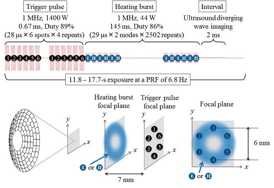
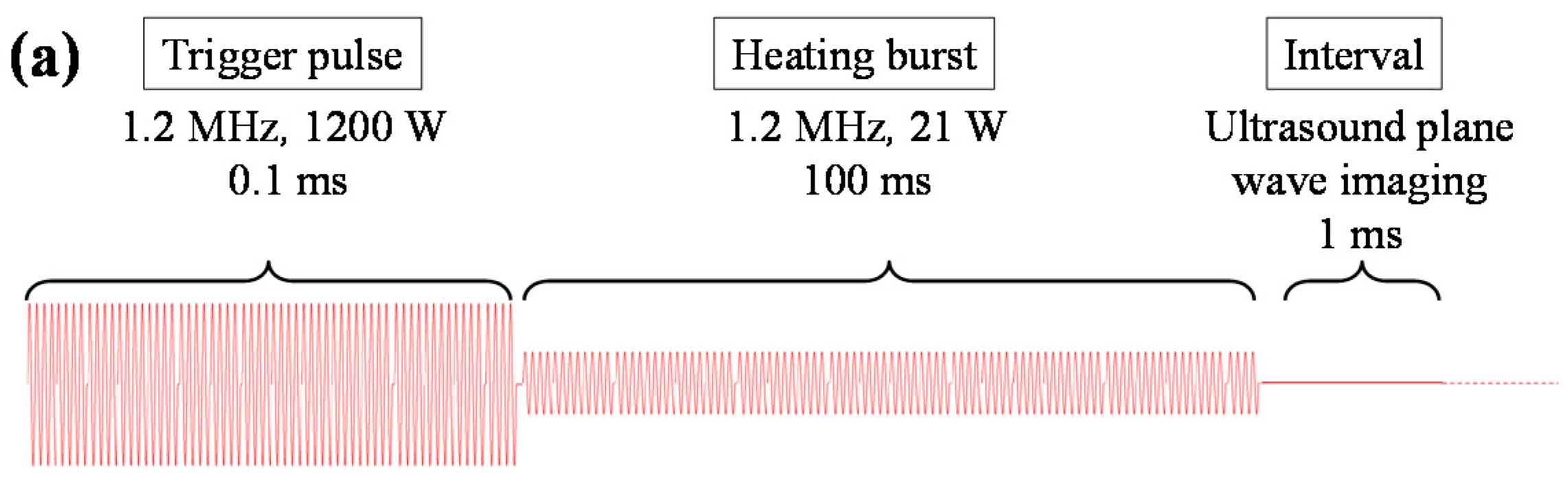
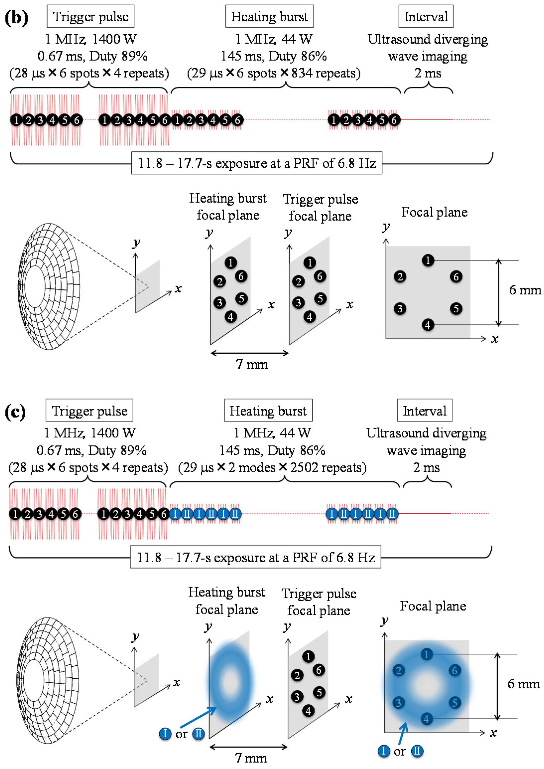
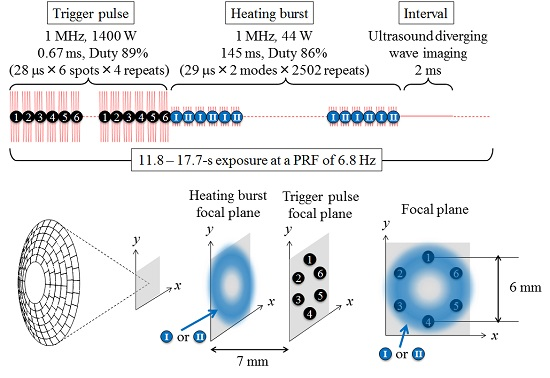
2. Trigger HIFU Sequence

The effect of bubble-enhanced heating was experimentally observed in a moderate intensity ultrasound field, such as ISPTA of 400 W/cm2 at a frequency of 2.18 MHz [15], ISPTA of 290 W/cm2 at 3.2 MHz [16], and acoustic power of 28.9 W at 1.85 MHz [19], when using ultrasound contrast agents (Levovist [15], Optison [16], and Definity [19]) consisting of encapsulated microbubbles. However, it is difficult to control the spatial distribution of such ultrasound contrast agents inside a body to locally enhance the ultrasonic heating. It causes the shift of the greatest heating position from the transducer focus to a pre-focal region [19].
To generate microbubbles containing slightly soluble gas inside a body, the usage of nanoparticles that can be vaporized into microbubbles by HIFU pulses or short bursts has been developed and investigated [23,37,38,39]. Such phase change nanoparticles enable us to control the region of microbubbles induced by HIFU pulses. In the studies, HIFU pulses with a duration of less than 100 μs and peak-negative-pressure of 2.4–15.5 MPa were used to vaporize nanoparticles. For the bubble-enhanced heating using nanoparticles [23], the pulse was followed by a long burst with a duration of 670 ms and acoustic power of 5.2 W, and this combination of the high intensity pulse and long burst was repeated for 30 s.
Even without injecting ultrasound contrast agents nor nanoparticles, it is possible to induce microbubbles inside a body by extremely high-intensity ultrasound pulses. The cavitation thresholds for a single or two-cycle focused ultrasound pulse were measured in several media, such as water, blood, kidney tissue, and so on [40]. Bubble clouds will be formed in the region where the peak-negative pressure exceeds the threshold, called “intrinsic threshold” [41]. The threshold range of peak negative pressure was from −26 to −30 MPa in the media with high water content. In another study, a threshold of −33 MPa was observed in water by a focused acoustic pulse, and it was considered that cavitation bubbles were originated from nanometer-sized nuclei [42]. In histotripsy, cavitation bubbles are induced by extremely high-intensity pulses with a peak-negative pressure exceeding the threshold range and a soft tissue is eroded by the collapse of the bubbles [43,44,45]. Although the intrinsic threshold is extremely high, an acoustic pulse with a longer duration can generate clouds of bubbles even at a lower intensity because of the mechanism called “shock scattering” [46]. The ultrasound waveform in a focal region at a high intensity has a steep and large peak-positive pressure and relatively small peak-negative pressure—for instance, +78 MPa and −15 MPa, respectively [46]—owing to the focusing of nonlinearly propagated ultrasound. Once cavitation bubbles are generated, they provide a pressure release surface converting the positive pressure to negative pressure, which exceeds the intrinsic threshold.
From a previous study for a cavitation-enhanced ultrasonic heating in 2003 [13], a trigger HIFU sequence consisting of high-intensity short pulses generate bubble clouds, named “trigger pulses”, and following moderate-intensity long bursts for the enhancement of the ultrasonic heating, named “heating bursts” was evolved. The typical duration of the trigger pulse was 10–100 μs. The duration time was set longer than the pulse duration of several μs in histotripsy studies [40,41,43,44,45]. Since a peak negative pressure of a typical trigger pulse did not exceed the intrinsic threshold, typically around −30 MPa, the relatively longer duration time was necessary to form bubble clouds through a shock scattering mechanism. The upper limit of the duration time was decided to avoid the effect of standing wave components—for instance, those caused by reflections between a HIFU transducer and HIFU focus or skin surface. This was under the consideration that standing wave components tend to decrease the cavitation threshold [47,48] and may make it difficult to locally generate bubble clouds in a HIFU focal region. The intensity of a heating burst was similar to that in conventional HIFU treatments. The duration time of a heating burst was in the order of 10–500 ms with a consideration of the sustaining duration of cavitation bubbles under the heating burst exposure. The effect of standing wave components on the generation of cavitation by a heating burst was not considered because the acoustic intensity of a heating burst was much less than that of a trigger pulse. As a result, the trigger HIFU sequence was similar to that used for the bubble-enhanced heating with nanoparticles [23]. In the trigger HIFU sequence, the typical acoustic intensity for cavitation generation was higher due to the lack of artificial cavitation nuclei. The duration time of the burst wave for the heat enhancement was shorter because lifetime of cavitation bubbles induced by the trigger pulse is considered to be shorter than that of microbubbles vaporized from nanoparticles with slightly soluble gas [38]. The advantage in the trigger HIFU exposure over the methods using nanoparticles is to have a potentially shorter lead time to be approved as clinical applications.
Figure 1 shows three examples of a trigger pulse sequence [35,36]. Table 1 lists the technics applied to the sequences shown in Figure 1. Figure 1a shows a typical sequence without the focus scanning. Since an ordinary HIFU focal spot has an ellipsoidal shape longer in the HIFU propagation direction, the lateral enlargement of the focal region can reduce the surface-area-to-volume ratio of the region, which decreases the effect of the heat diffusion outward from the region to be treated. In the sequences shown in Figure 1b,c, trigger pulses were rapidly scanned at focal points of ①–⑥, named “multi-trigger HIFU sequence”. The focal point was electronically scanned using a 2D array transducer at each corner of a regular hexagon 3 mm each side. The whole hexagonal region was coagulated by thermal conduction between adjacent focal spots. The total acoustic power for the spot scanning of trigger pulse and heating burst were 1400 and 44 W, respectively. The duration and interval time for trigger pulses at each focal point were 25 and 3 μs, respectively. The trigger pulses were laterally scanned four times. For heating bursts, the same total acoustic power, duration, and duty cycle were used for both spot scanning in Figure 1b and direct synthesis of focus in Figure 1c. The focal region of the heating bursts in Figure 1c has a ring shape, marked with Ⓘ or II . A sector vortex method [49,50] with a vortex mode number of 4 was applied to generate the ring focal region covering six foci of scanned trigger pulses with a spiral wave front. The simulated pressure fields with assuming linear propagation and neglecting attenuation are shown in Figure 2. The duration and interval time were 25 and 4 μs, respectively. The focal spot was scanned 834 times in Figure 1b and the spiral direction of the wave front was switched 2502 times in Figure 1c. The subtotal durations of trigger pulses and heating bursts were 0.67 and 145 ms, respectively. Immediately after the end of the heating bursts, a 2 ms interval time was reserved for ultrasonic imaging. The sequence was repeated for 80 or 120 cycles. Since cavitation clouds formed through the shock scattering tend to grow backward from the focal point, the focal points of trigger pulses were intentionally shifted by 7 mm forward from the geometrical focal plane to match the axial position of the generated cavitation clouds to that of the heating focus.

3. High-Speed Observation of Cavitation Bubbles Induced by Trigger HIFU Exposure

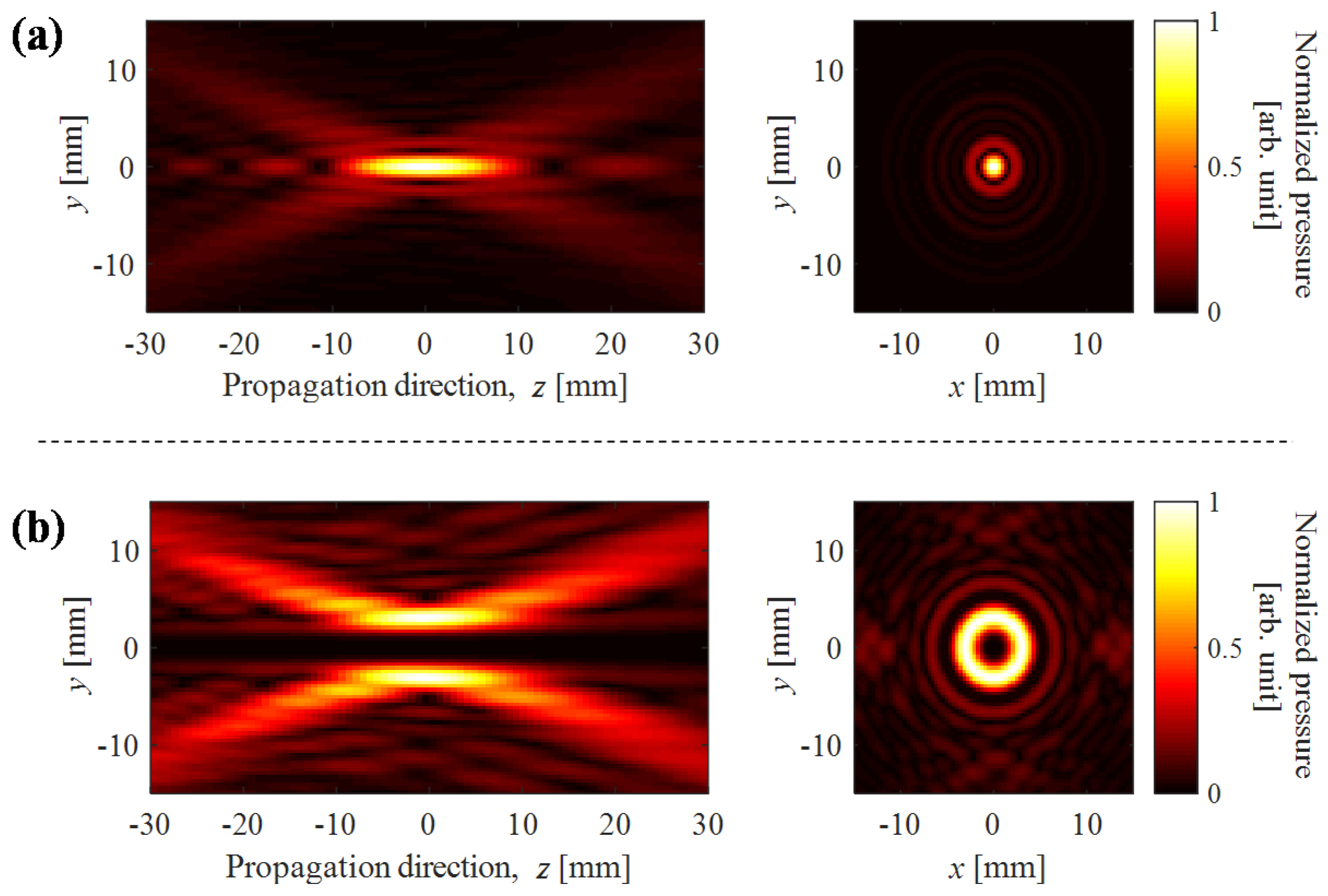
3.1. Cloud Cavitaion Formation by Dual-Frequency Ultrasound Exposure

When the shock scattering phenomena is used to form bubble clouds, negative and positive pressures have different roles. After negative pressure generates cavitation bubbles enough to provide a pressure release surface, positive pressure is converted to negative pressure exceeding the intrinsic threshold and forms cavitation clouds. Either peak negative or positive pressure can be emphasized by superimposing the second-harmonic ultrasound onto the fundamental component [51,52,53,54].
Figure 3 shows the schematics of four kinds of second-harmonic superimposed sequences, PP, NN, PN, and NP sequences. 1.6-MHz ultrasound was superimposed onto a 0.8-MHz ultrasound to emphasize either peak positive pressure (P wave) or peak negative pressure (N wave) in the earlier and later periods of 62.5 μs duration by adjusting the phase difference between the two frequency components. Cavitation bubbles generated in a poly(acryl amide) (PAA) gel at an acoustic intensity of 42 kW/cm2 were observed with a high-speed camera (HPV-2A, Shimadzu, Kyoto, Japan) at a frame rate of 500 kfps with an exposure time of 250 ns. The results are shown in Figure 4 [54]. A 128-element array transducer with both diameter and focal length of 100 mm (Imasonic, Voray sur l’Ognon, France) was placed in a water tank so that the ultrasound focus was located in the gel phantom in degassed water. The second-harmonic superimposed voltage was applied from 128-channel stair case voltage drive amplifiers (Microsonic, Tokyo, Japan). The temperature and dissolved oxygen in water were kept at 37 °C and 20%–23%, respectively. The gel included 22.5% bovine serum albumin (BSA).
In the results with the NP sequence, cavitation clouds were formed immediately after the P-wave exposure started, while no cavitation clouds were observed in all five of the results with the NN and PN sequences. There was only one case in which the cavitation cloud formation was observed with the PP sequence. The clouds were formed by the NP sequence with the highest reproducibility among the four sequences. The measured peak-positive and negative pressures of the P-waves were +60 and −8 MPa, respectively, and those of the N-waves were +11 and −9 MPa, respectively, at an intensity of 25 kW/cm2. Therefore, the N-waves did not produce a peak-negative pressure exceeding the intrinsic threshold even when the waves were reflected by bubbles. However, the slightly greater peak-negative pressure than that of the P-waves contributed to the production of significantly more scattered bubbles, which increased the probability of the cloud formation through a shock scattering mechanism during the exposure of the immediately following P-waves. The results clearly show the different roles of peak-negative and positive pressures for the formation of bubble clouds when the peak-negative pressure does not exceed the intrinsic threshold.

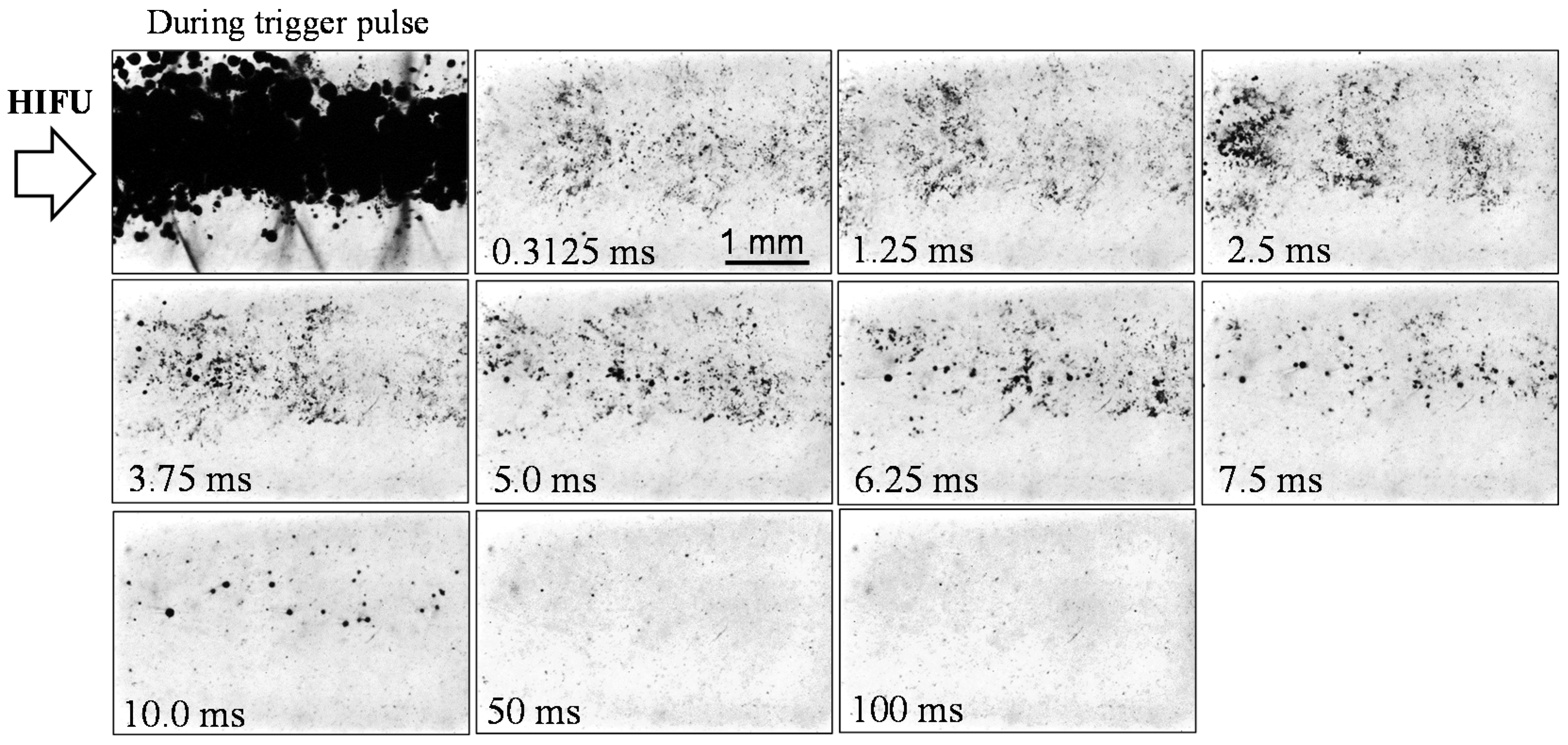
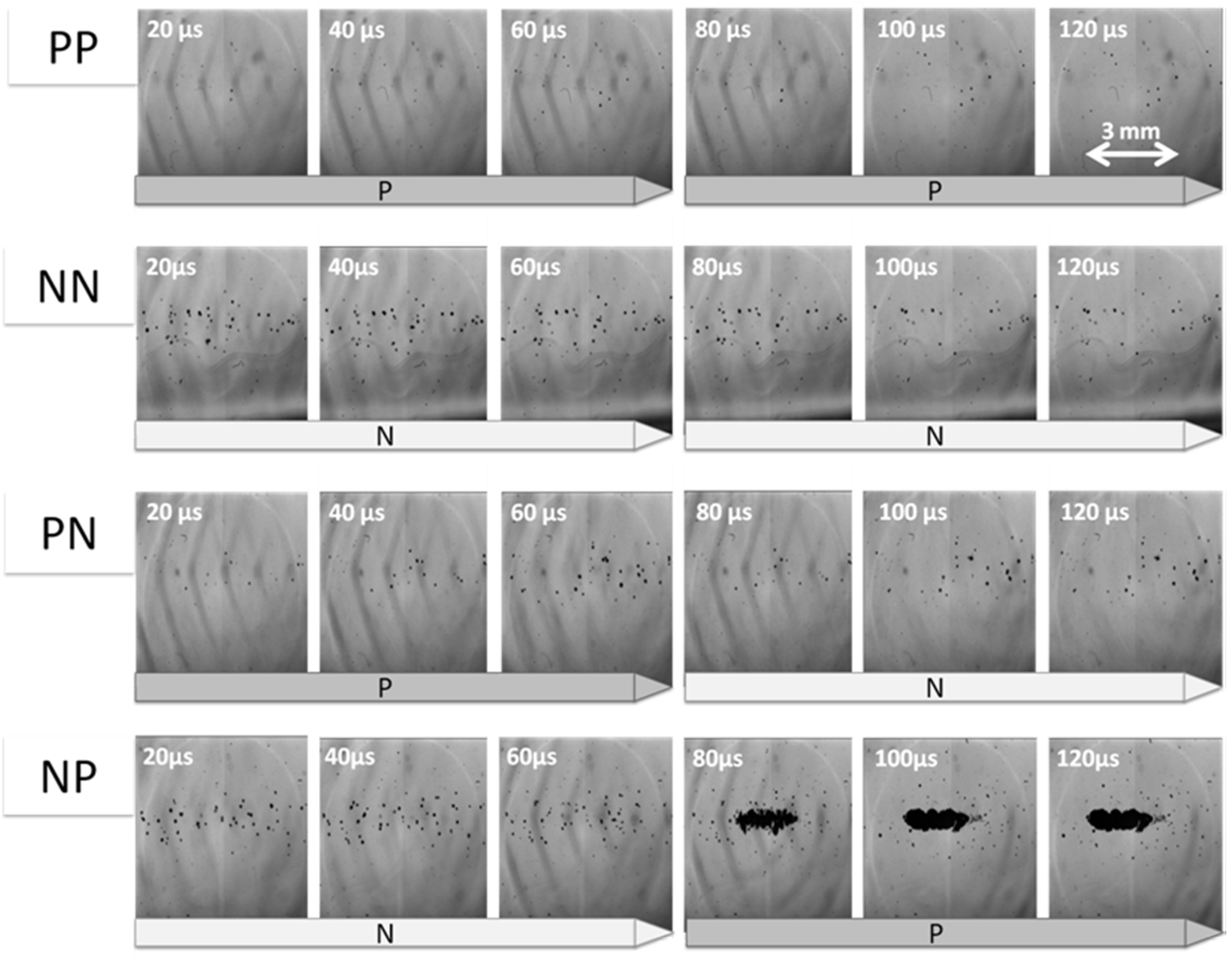
3.2. Lifetime of Cavitaion during and after HIFU Exposure

The dissolution time of air microbubbles without any shells is on the order of tens of milliseconds [55], which is much shorter than that of encapsulated contrast agents with slightly soluble gas. Cavitation bubbles are considered to be free bubbles and mainly consist of vapor and dissolved gases in an ambient medium. Therefore, a high-speed monitoring method is necessary to detect cavitation bubbles before they dissolve quickly. A high-speed ultrasonic imaging using plane-wave transmission at a frame rate of thousands of frames/s [56] has been used to monitor residual cavitation microbubbles after the exposure of a high-intensity pulse [57,58]. The two studies showed that the lifetime of cavitation bubbles was less than a few tens of milliseconds in tissue samples of sheep thigh muscle [57] or chicken breast [58].
In the trigger HIFU exposure, cavitation bubbles induced by the trigger pulse are forced to oscillate by the heating burst. When bubbles oscillate under alternating pressure, the effect of rectified diffusion [59,60,61] contributes to suppressing bubble dissolution. An attractive force for oscillating bubbles such as Bjerknes force [62] causes the bubble coalescence [63], which reduces the pressure contribution from the surface tension inversely proportional to the bubble radius then slows the gas dissolution to the surrounding medium. The fission of collapsing bubbles owing to the surface instability induces the fragmentation of the bubbles. The fission process has an additional damping effect on the energy dissipation of a spherically oscillating bubble [64], which can lead to the greater enhancement of the ultrasonic heating by the heating burst.
Figure 5 shows the high-speed images of bubble clouds generated by a trigger pulse and cavitation bubbles oscillated by a heating burst in a HIFU focal region [36]. The target was a PAA gel including 15% BSA placed in a water tank. They were taken with a high-speed camera (Phantom v310, Vision Research, Wayne, PA, USA) at a frame rate of 3.2 kfps with an exposure time of 20 μs. A 690-nm pulse laser with a pulse width of 20 ns (CAVILUX Smart, Cavitar, Tampere, Finland) was used as a backlight source. The temperature and dissolved oxygen in water were kept at 20 °C and 23%–28%, respectively. The acoustic source was a 256-element array transducer (Imasonic, Voray sur l’Ognon, France) with both diameter and focal length of 120 mm. The transducer was connected to 128-channel stair case voltage drive amplifiers [65] (Microsonic, Tokyo, Japan) by electrically combining two adjacent elements and driven at 1.2 MHz. The applied trigger HIFU sequence is shown in Figure 1a. The instantaneous total acoustic power of the trigger pulse was 1200 W and that of the heating burst was 21 W. The duration times of the trigger pulse and heating burst were 0.1 and 100 ms, respectively. Figure 6 shows the ultrasonic images of a different type of PAA gel phantom containing a 0.5% graphite layer with a thickness of 0.75 mm to investigate ultrasonic contrast ratio between bubbles and linear scatterers [36]. A pulse inversion (PI) method [66] with two-plane wave transmissions was used to monitor residual bubbles in the graphite gel plane 0.9 ms after the stop of the heating burst exposure with duration times of 0, 1, 10, or 100 ms. The differences in PI images before and after the HIFU exposure were calculated to reduce the effect of graphite particles.
A cavitation cloud of many expanded bubbles is seen in the first optical image in Figure 5 during the trigger pulse exposure. No cloud formation is observed after the stop of the trigger pulse during the heating burst exposure. While the mean bubble radius increased [36] probably because of the effects of coalescence and rectified diffusion during the heating burst exposure, the bubbles gradually disappeared and only a small number of bubbles are observed in the images 50 ms after the trigger pulse exposure. As a result, the typical lifetime of the cavitation bubbles seemed to be several ms in the high-speed photographs. However, many bubbles were detected by high-speed ultrasonic imaging even after 100-ms exposure of the heating burst as shown in Figure 6f. The ultrasonic contrast ratio after and before the HIFU exposure was calculated using the mean square of the reconstructed IQ data detected from the calculation area corresponding to 57–63 mm in depth and −10–10 mm in the width direction, where the origin is set at the center of the probe. The contrast ratio was almost constant even 10 ms after the trigger pulse exposure. The ratios were 25 dB at 10 ms and 22 dB at 100 ms, respectively [36]. It is probably because much smaller bubbles than the camera resolution of 3.3 μm/pixel in the experiments remained, although it is still unclear what kind of mechanisms stabilized such microbubbles. In other studies using chicken breast tissue as a target, cavitation bubbles were ultrasonically monitored by pulse inversion imaging during interval times just after heating bursts with durations of 135 [34] and 145 ms [35].

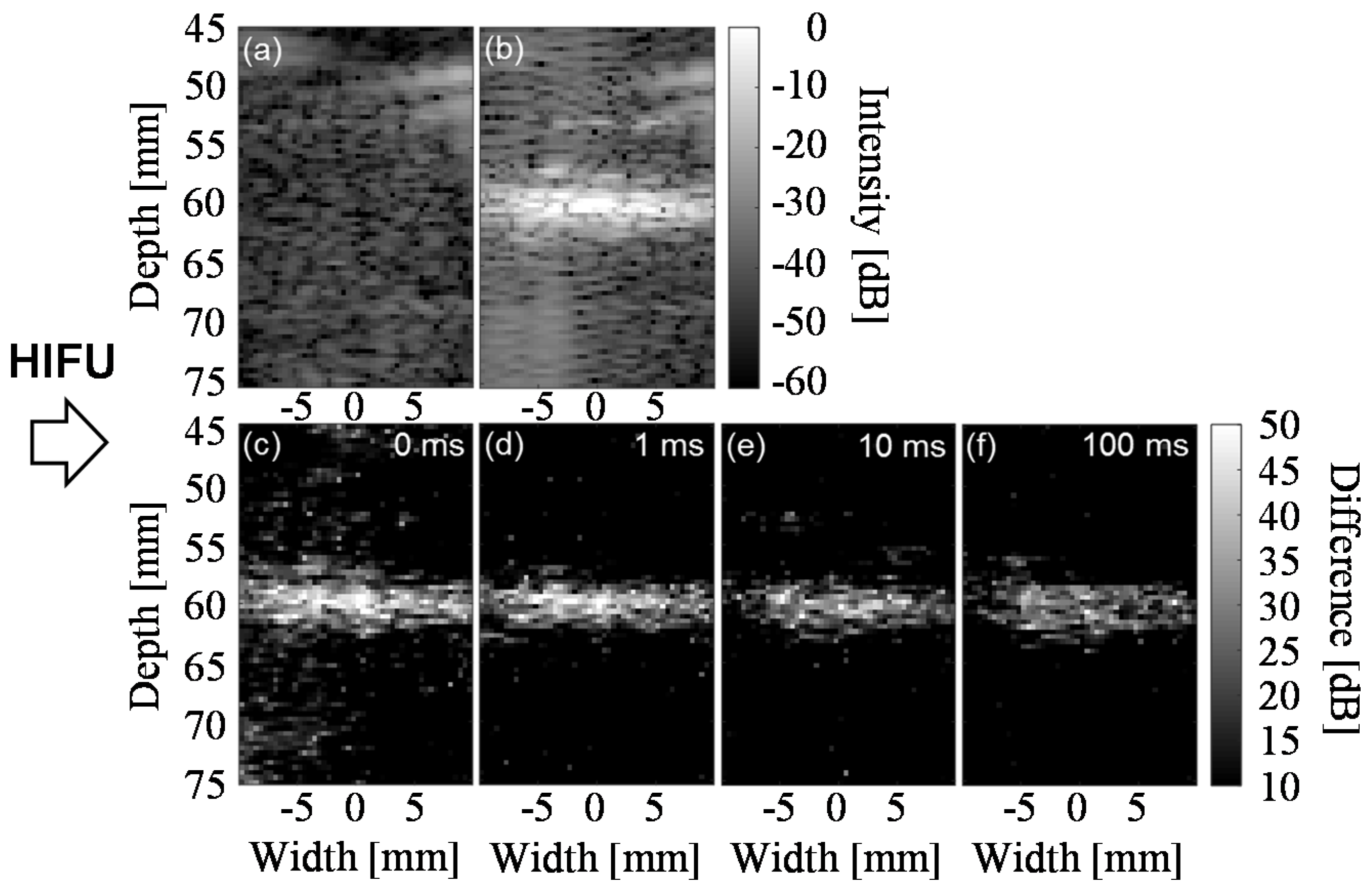
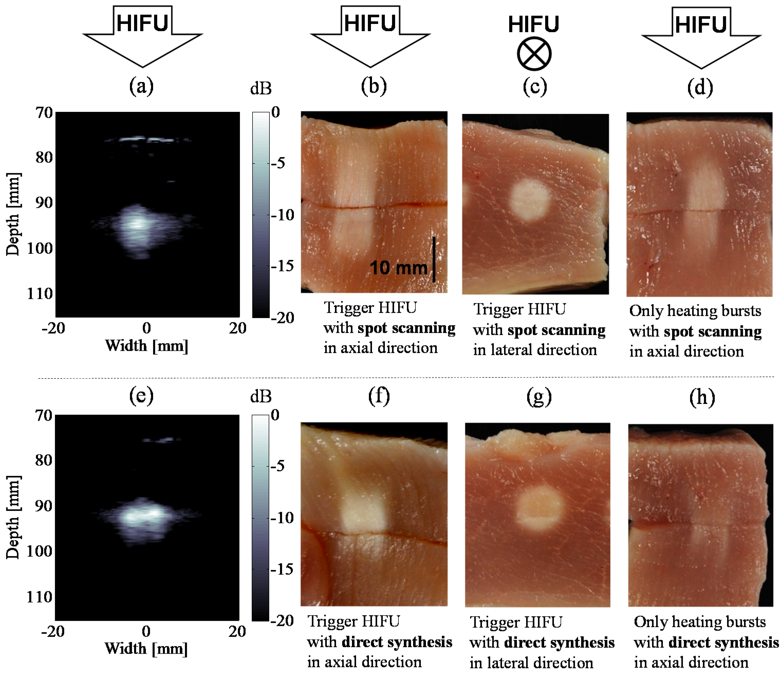
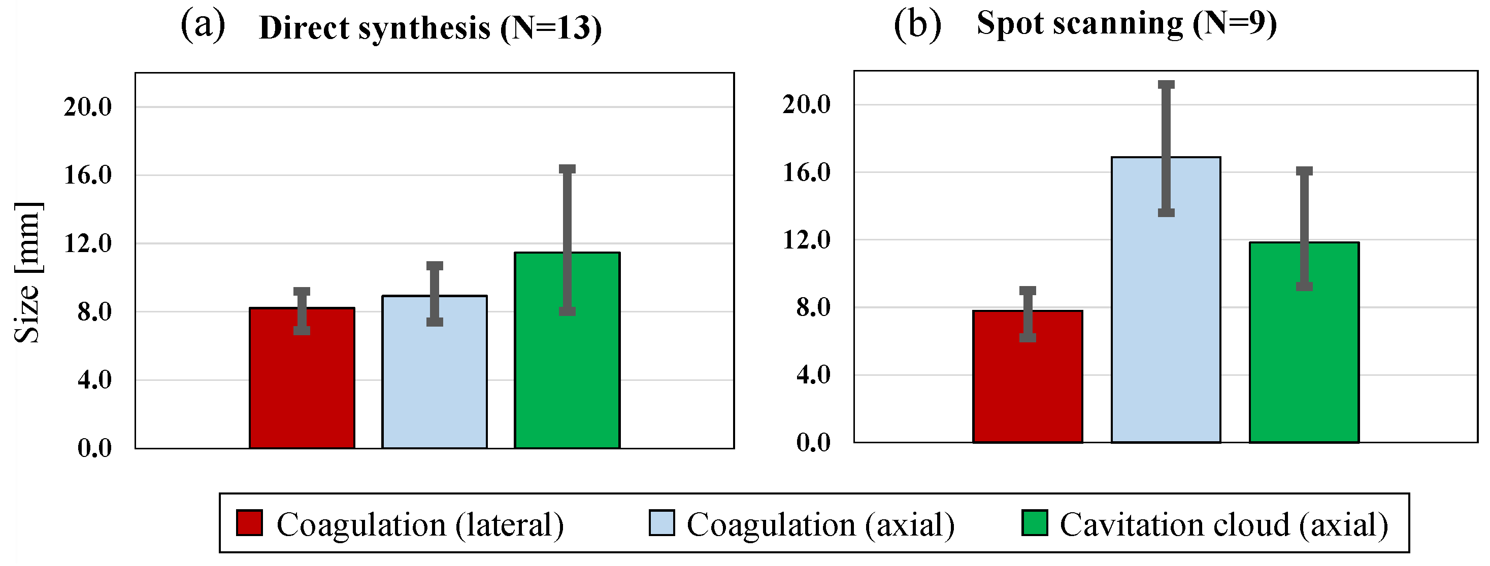
3.3. Cavitation Generated in Multiple Focal Spots

Methods of focal spot scanning have been investigated for highly efficient ultrasonic heating [67,68,69,70,71]. In the studies, the distribution of estimated temperature was used as a feedback information to obtain uniform thermal doses in the larger target regions than that by a conventional HIFU exposure. The larger coagulation region contributed to the efficient use of the ultrasonically generated heat through minimizing the surface-area-to-volume ratio. Similarly, as mentioned in the previous section, multi-trigger HIFU sequences for the lateral enlargement of the treated region have been investigated to effectively coagulate a target tissue [29,32,33,34,35].
Figure 7 shows the high-speed images of bubble clouds generated by trigger pulses in six focal positions [34]. The target was a PAA gel including 15% BSA placed in a water tank. The images of bubbles were taken with the same camera and pulse laser in the experiment of the previous subsection though the optical magnification was smaller than that in the previous experiment. A HIFU transducer and driving system were also the same. The driving frequency was 1 MHz in this experiment. The temperature and dissolved oxygen in water were kept at 36 °C and 20%–30%, respectively. The applied trigger HIFU sequence was similar to that shown in Figure 1b. The differences were the acoustic powers, the interval time between the heating bursts focused at the adjacent focal positions, and the position of the focal plane of trigger pulses. The instantaneous total acoustic powers of the trigger pulses and heating bursts were 1900 and 65 W, respectively. The duration and interval time of the heating bursts were 25 and 2 μs, respectively. The intentional focal plane shift of the trigger pulses was not applied in this case.
Bubble clouds in the two focal positions are seen in the first picture of Figure 7 at 50 μs when the second trigger pulse is exposed. At 650 μs, almost the end of the first set of the trigger pulses, cavitation bubbles are observed in the expanded area corresponding to the six focal positions. After 10 s of HIFU exposure, bubble clouds were generated in the almost same position and region to that at the beginning of the HIFU exposure as shown in the first picture of Figure 7. Cavitation bubbles in a much larger region than that by a single spot focus method can be used to accelerate a HIFU treatment by the rapid spot scanning method.

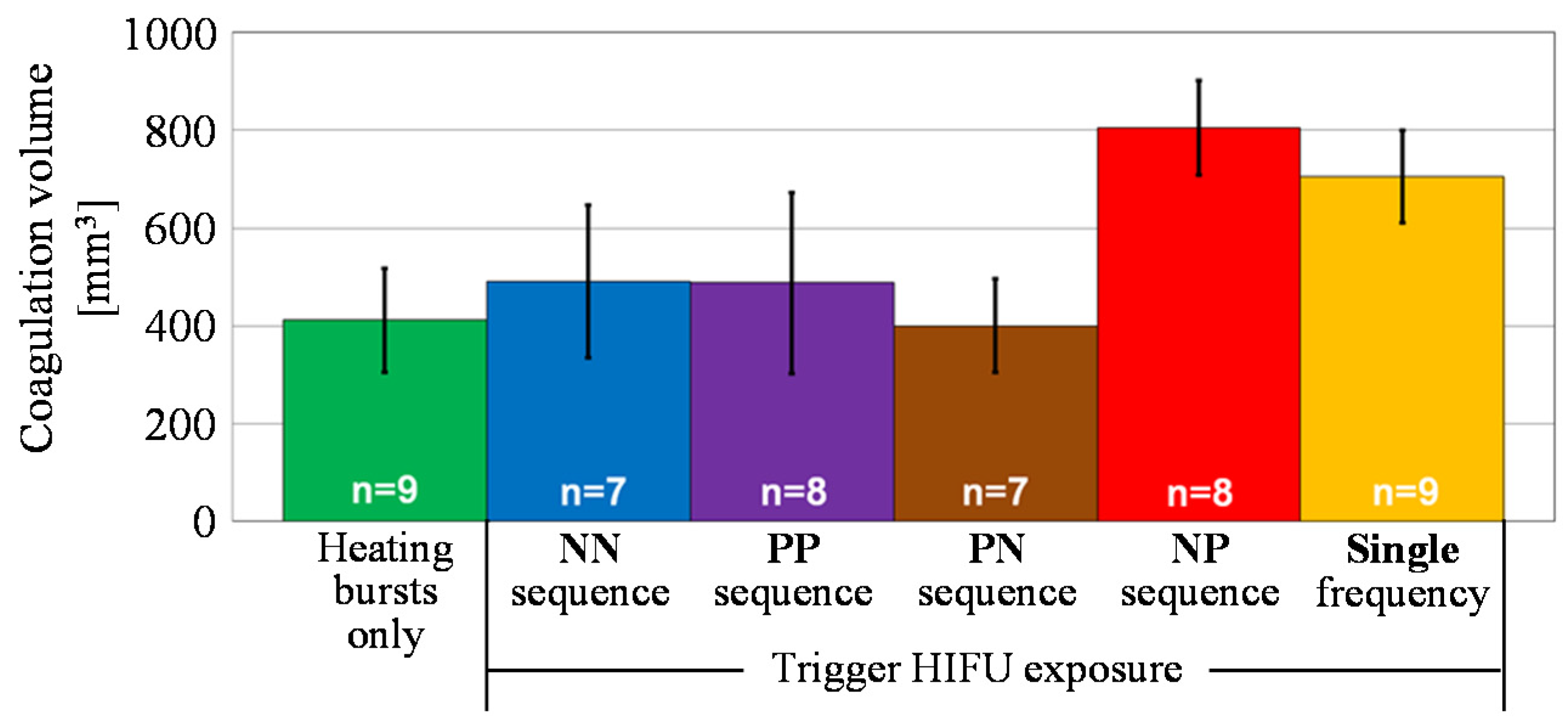
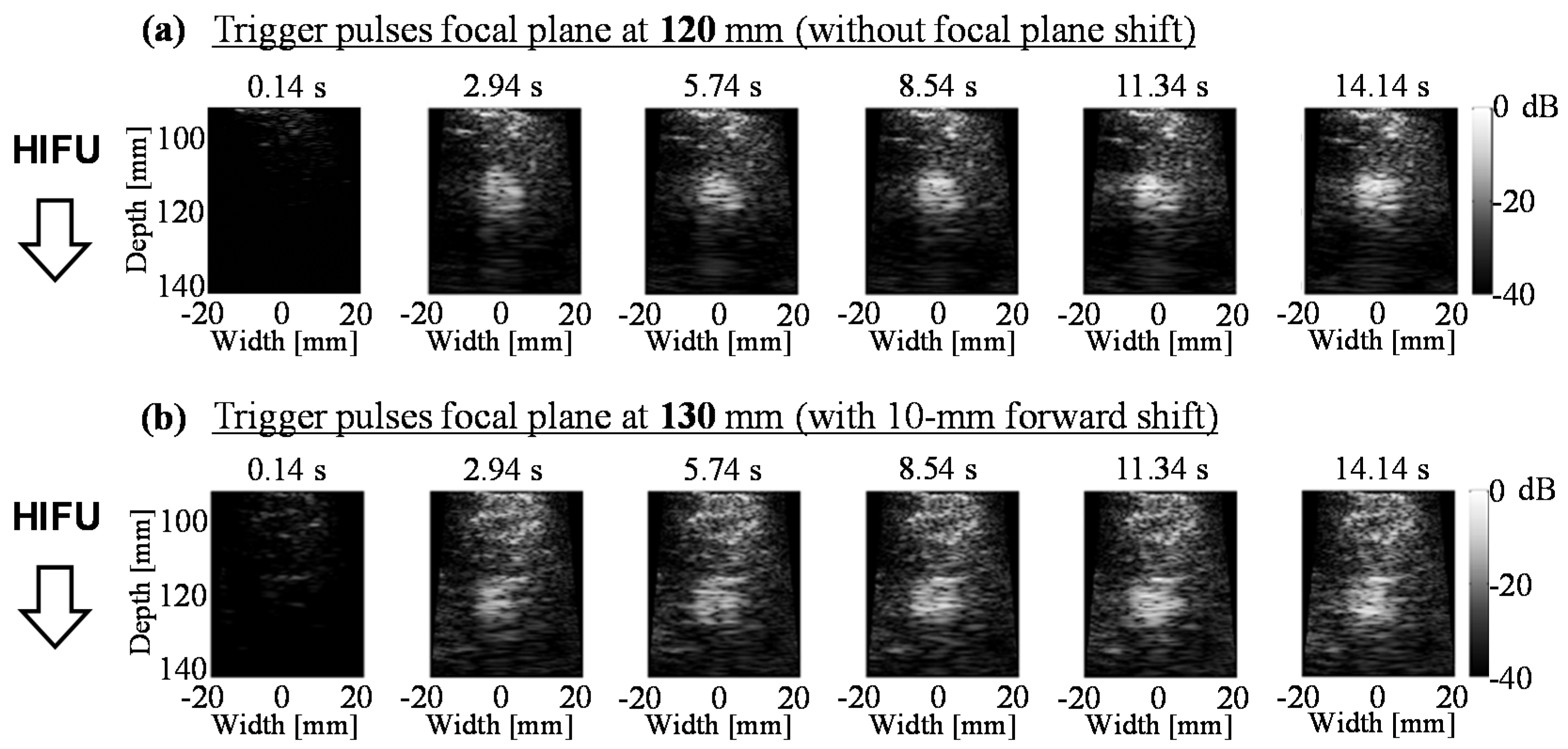
4. Temperature Increase and Coagulation Region by Trigger HIFU Exposure

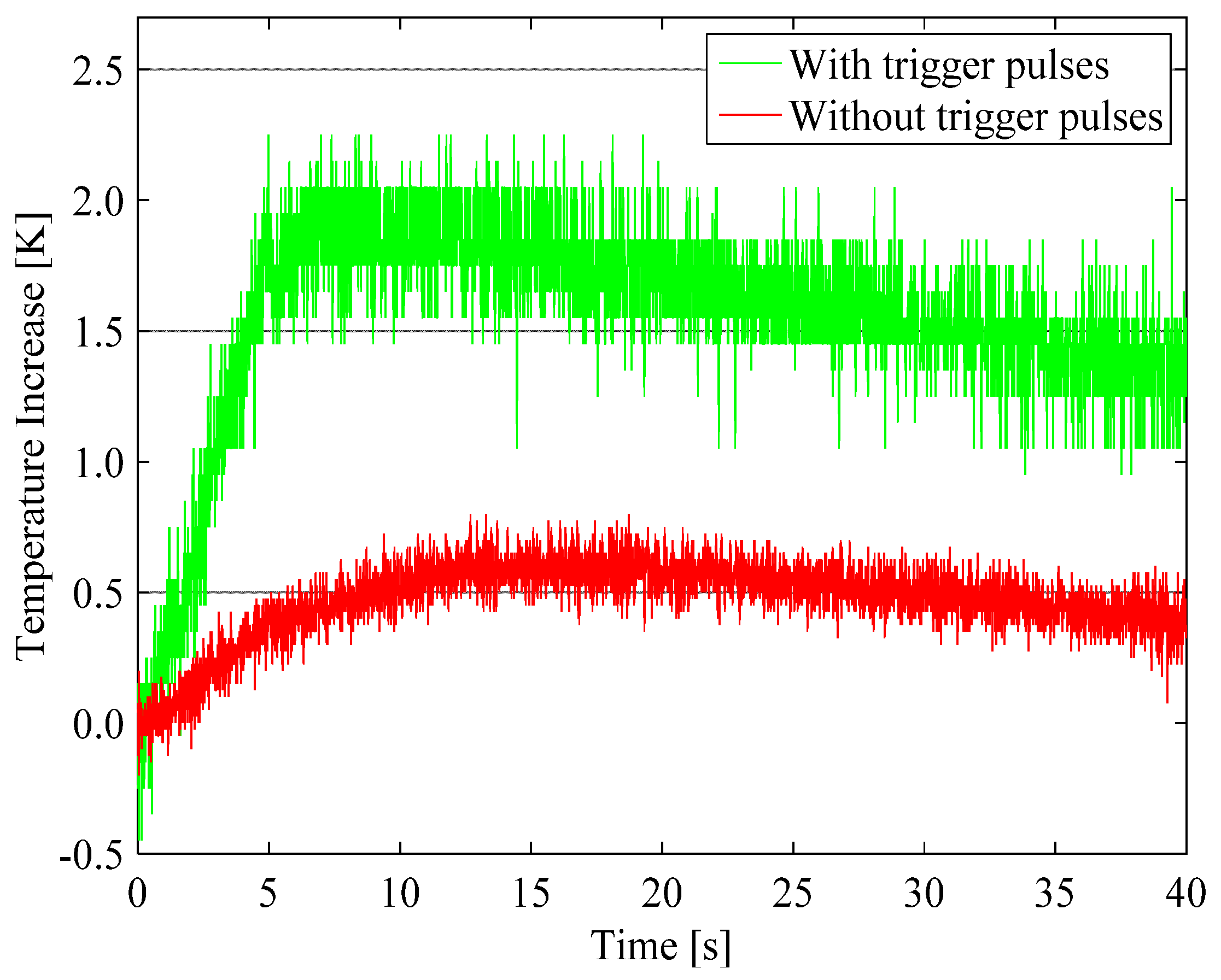
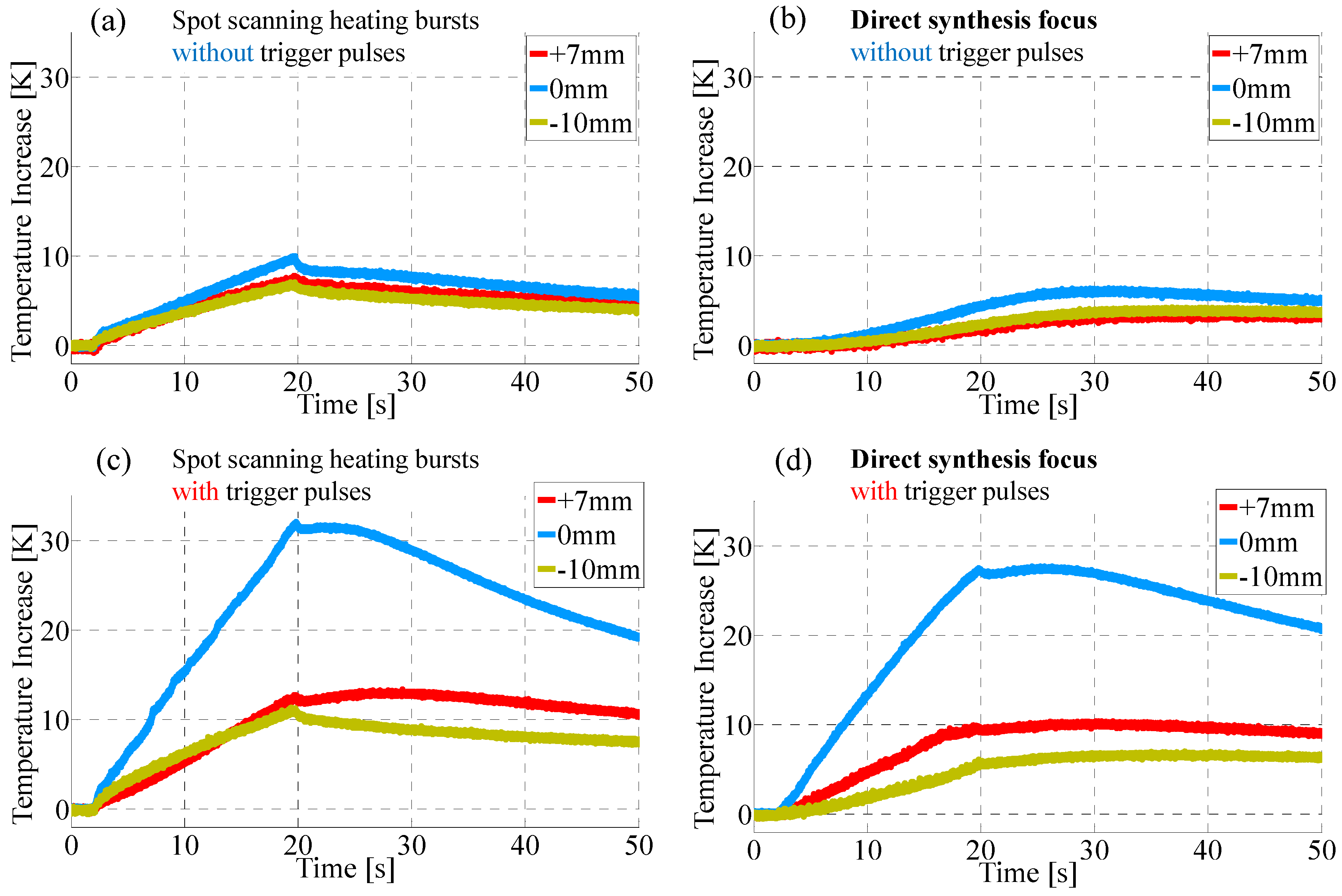
4.1. Enhancement of Temperature Increase by Trigger Pulses

The effect of bubble-enhanced ultrasonic heating has been quantitatively assessed by measuring temperature increase with a thermocouple or magnetic resonance (MR) thermometry in many studies [11,13,15,16,17,18,19,20,21,22,23,30,31,32,33,35].
Figure 8 shows the temperature increases with and without the exposure of trigger pulses in a PAA gel including 15% BSA placed in a water tank [31]. The temperature was measured at a lateral distance of 2.7-mm above the HIFU focus with a sheath thermocouple of 0.15 mm in diameter (K-type, Chino, Tokyo, Japan). The certain distance away from the HIFU focus was to reduce the effect of viscous heating. The trigger pulse sequence was similar to that shown in Figure 1a. The driving frequency was 1.2 MHz. The instantaneous total acoustic powers of the trigger pulses and heating bursts were 900 and 13 W, respectively. The duration times of trigger pulses and heating bursts were 0.1 and 499.9 ms, respectively. There were no interval time for ultrasound imaging and the total duration time of HIFU exposure was 5 s. The result without trigger pulses was averaged over four measurements to provide the baseline for comparison.
The maximum temperature increase and the temperature increase 35 s after the stop of HIFU exposure (t = 40 s) in the trigger pulse sequence were approximately three times as large as those without trigger pulses. Comparing the heat enhancement by cavitation with the results in other studies, the temperature increase in an agar phantom with a 10.2 s exposure at 1.42 MPa and 1 MHz at 0.5 mm away from the focus was approximately three times as large as that at 1.39 MPa [11], and the maximum temperature increase in an ex vivo porcine liver sample with a combination of 0.5 s burst at 500 W and 30 s exposure at 20 W and 1.2 MHz was 155% of that without a 0.5 s high-intensity burst [22]. The comparable ratio of the temperature increase with to without the trigger pulses for a long time range in this study indicates that the ultrasonic heat generation in the gel should have also increased approximately threefold by the effect of cavitation bubbles. However, as the estimated ultrasonic absorption coefficient of the gel by fitting between the measurement and thermal simulation result was 1.28 Np/m, which is much less than the typical value of soft tissues, the temperature increase ratio in a soft tissue would be less. This ratio may be improved by increasing the intensity or repetition frequency of trigger pulses.
Figure 9 shows temperature increases in a PAA gel including 15% BSA placed in a water tank by spot scanning sequences as shown in Figure 1b,c [35]. The temperature increases measured with a sheath thermocouple of 0.3 mm in diameter (K-type, Chino, Tokyo, Japan) were averaged over two measurements at the geometric focus, and 10 mm backward and 7 mm forward from it. The results without and with the trigger pulse exposure are shown in Figure 9a–d, respectively. Spot scanning heating bursts shown in Figure 1b and heating bursts with a directly synthesized focus in Figure 1c were exposed in the case of Figure 9a–d, respectively. The triggered HIFU sequences shown in Figure 1b,c were used for the results shown in Figure 9c,d, respectively. A HIFU transducer and driving system were the same as used for the experiments shown in Figure 7. The HIFU exposure was started at approximately t = 2 s and the total duration time of HIFU exposure was approximately 17.7 s.
In the results without the trigger pulses, the maximum temperature increases with spot scanning heating bursts in Figure 9a,c are greater than those with a directly synthesized focus in Figure 9b,d, respectively. It is reasonable because the pressure amplitude along the beam axis of the directly synthesized focus should be constantly zero as shown in Figure 2b, and there was thereby no heat source at the measurement point when the linear ultrasonic propagation is assumed, while the measurement point was located in the side lobes of the spot scanning heating bursts. Comparing the results at the geometric focus between the case of Figure 9a,b, the temperature increase in Figure 9a at each position is greater than that in Figure 9b not only at the end of but also after the HIFU exposure until t = 50 s, which means the total amount of generated heat in Figure 9a is greater than in Figure 9b. It is because of the increased ultrasonic absorption owing to the higher harmonic ultrasonic components caused by the effect of nonlinear ultrasonic propagation, which is greater in a spot focus sequence than in an enlarged focal region such as the directly synthesized focus. On the other hand, with the trigger pulses, the temperature increase at the geometric focus after t = 37 s with the directly synthesized focus in Figure 9d is greater than with the spot scanning heating bursts in Figure 9c. Furthermore, the enhancement of temperature increase by cavitation bubbles at 20.3 s, when the effect of viscous heating is significantly reduced, was approximately 6.1 times for the direct synthesis, which was nearly twice as significant as the spot scanning. The results indicate that ultrasonic absorption caused by cavitation bubbles was significantly more dominant for the trigger HIFU heating with the direct synthesis than that with the spot scanning.

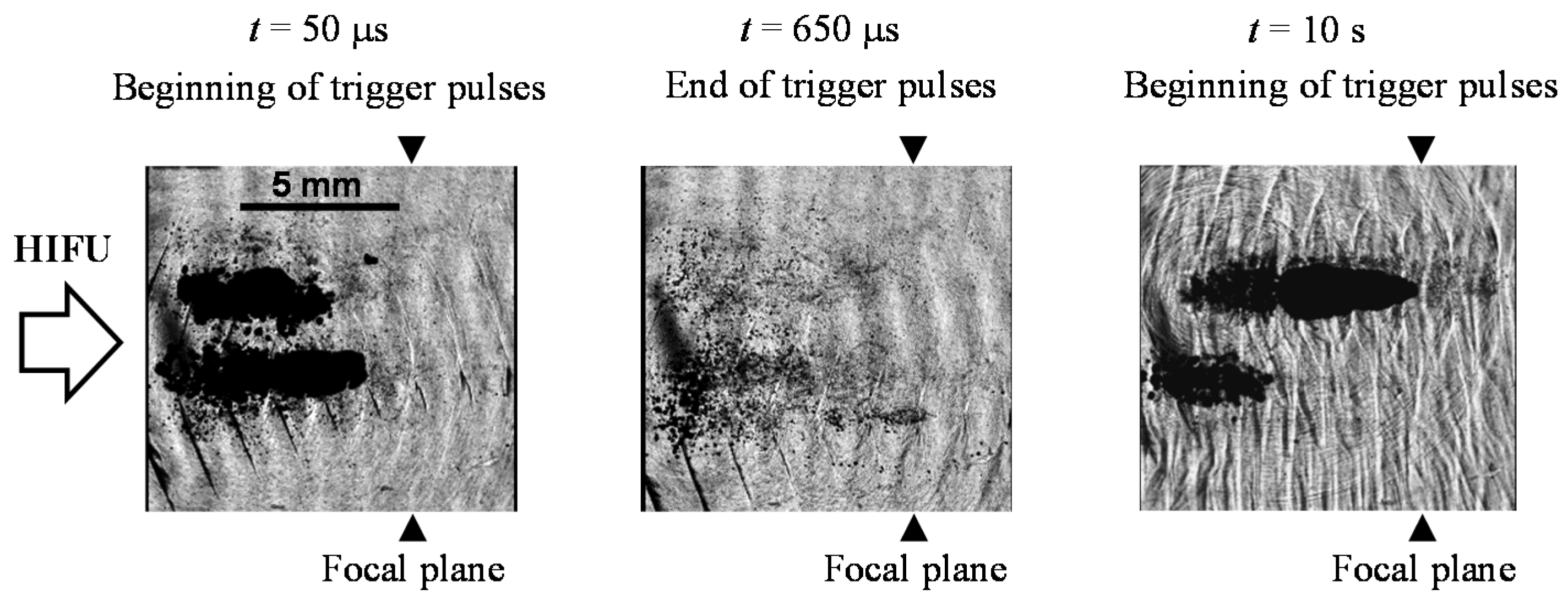
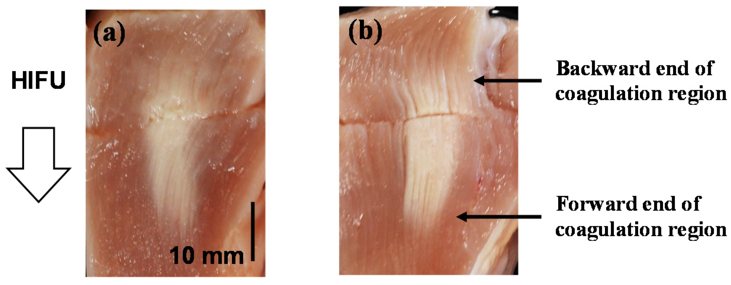
4.2. Coagulation Region Size and Predictability

Multi-trigger HIFU sequences using spot scanning trigger pulses can generate a large coagulation volume of a nearly cylindrical shape [32,33,34,35]. Figure 10 shows coagulation volumes and their standard deviations of chicken breast tissues by various HIFU sequences [33]. Each coagulation volume was calculated as a cylindrical column, whose diameter and height were measured in its frontage and depth sections, respectively. The acoustic source was a 128-element array transducer (Imasonic, Voray sur l’Ognon, France) with both diameter and focal length of 120 mm. The HIFU driving system was the same used for the experiments shown in Figure 5, Figure 6 and Figure 7, and Figure 9. The applied trigger HIFU sequences were similar to that shown in Figure 1b. The total HIFU exposure was 11 s. For the trigger pulses, a single-frequency ultrasound at 0.8 MHz or dual-frequency ultrasound at 0.8 and 1.6 MHz as shown in Figure 3 with a duration of 50 μs and acoustic intensity of 10 kW/cm2 was used. The interval time of the trigger pulses was 3 μs and the resulting subtotal durations was 1.272 ms. The intentional focal plane shift of the trigger pulses was not applied in this case. The same heating bursts were used in all sequences. The driving frequency was 1 MHz and the acoustic intensity was 1.7 kW/cm2, corresponding to an instantaneous total acoustic power of 51 W. The duration and interval time of the heating bursts were 25 and 2 μs, respectively, resulting in the subtotal durations of 135.1 ms. The temperature and dissolved oxygen in water were kept at 36 °C and 20%–30%, respectively.
As shown in Figure 10, the average coagulation volumes by the NP and single-frequency sequences were significantly larger than those by the other sequences. Especially, the volume by the NP sequence was almost two times larger than that by the sequence without trigger pulses. The results show that the trigger pulses in the NP and single-frequency sequences were effective for employing cavitation bubbles in the chicken breast for the ultrasonic heating while the trigger pulses in other sequences were not. This indicates that the trigger pulses in the NP and single-frequency sequences could generate sufficient amount of cavitation bubbles through the formation of cavitation clouds, but the others could not, as shown in Figure 4. A small difference of p = 0.054 is seen between the results by the NP and single-frequency sequences with the same acoustic intensity of the trigger pulses estimated by assuming a linear relation between the input electric power and acoustic intensity, although the total acoustic power of the trigger pulses in the NP sequence was less than that in the single-frequency sequence because of a smaller focal region by the second-harmonic superimposition.
Cavitation clouds are formed backward from a focal point, in other words, toward a HIFU transducer, through a shock scattering phenomena [34,46,53,54]. In the trigger HIFU heating, the mismatch between the center position of bubble clouds and focal plane of heating bursts may have caused a less predictable coagulation pattern. Figure 11 shows high-speed pulse inversion images of cavitation clouds by transmitting diverging waves in chicken breast tissues during HIFU exposure without and with the focal plane shift of the trigger pulses to adjust the cloud position to the heating burst focal plane [34]. The applied HIFU sequence was the same used for the experiments shown in Figure 7 except for a focal plane shift by 10 mm. The focal plane of the heating bursts was the same as the geometric focal plane corresponding to a depth of 120 mm. The total HIFU exposure time was 16.5 s. After the HIFU exposure, cross-sectional pictures of the coagulated chicken breast tissues were taken to investigate the position of the coagulation region and the sharpness of the coagulation region boundary from their brightness distribution. Figure 12 shows typical pictures of the coagulated tissues. Table 2 shows thicknesses of intermediate brightness regions at the ends of a coagulation region in a chicken breast tissue without and with a focal plane shift of trigger pulses [34]. The thickness was calculated from the region where the brightness changed from 20% to 50% of the maximum.
In ultrasound images, a significant difference in the position of the bubble clouds is seen between the focal plane shifts of 0 and 10 mm shown in Figure 11a,b, respectively. The position of the clouds shifted by 5–10 mm backward from the geometric focal plane without a focal plane shift. In contrast, it was approximately on the geometric focal plane with a focal point shift of 10 mm. Although the appropriate distance of the focal plane shift may depend on each situation, the real-time ultrasonic imaging of cavitation bubbles seemed to be useful for adapting the amount of the shift. The brightness distribution of coagulated chicken breast tissues showed that the coagulation region significantly shifted backward from the geometric focal position without a focal plane shift. Furthermore, the coagulation region with the focal shift had more distinctive boundaries along the HIFU propagation direction, especially at the forward end of coagulation regions as shown in Table 2. The results show that an intentional focal plane shift of trigger pulses to match the cavitation clouds position to the focal region of heating bursts will make the trigger HIFU treatment more accurate and predictable. However, the lengths of coagulation regions with and without a focal plane shift were longer than those of cavitation regions in ultrasound images, especially in the backward direction. One of the possibilities is the effect of nonlinearly distorted waveform owing to the high acoustic intensity and focusing effect. The higher harmonic components of the distorted ultrasound increase ultrasonic absorption especially in the region shallower than the focal depth.
To investigate the effect of the nonlinear ultrasonic waveform, the results using the sequences shown in Figure 1b,c were compared. As the directly synthesized focus using a sector vortex method has a large focal region, a spatial peak acoustic intensity is much less than that by the spot scanning. It reduces the ultrasonic absorption caused by the nonlinear propagation and focusing. Figure 13 shows typical results of ultrasound images of cavitation bubbles during the HIFU exposure and slices of chicken tissue samples after the HIFU exposure [35]. Heating bursts of spot scanning and direct synthesis were exposed for Figure 13a–h, respectively. Trigger HIFU sequences shown in Figure 1b,c were applied for Figure 13a–c,e–g, respectively. The total HIFU exposure time was 11.8 s. Time-averaged variance images of high-speed pulse inversion data by transmitting diverging waves were used for the ultrasound cavitation images because the acoustic signals from cavitation bubbles change much more in time and space than those from tissue itself. The variance was calculated from the absolute value of complex signals (IQ data) corresponding to every five consecutive B-mode images and the variance images were then averaged. Since the variance of the background was approximately 30 dB lower than the maximum variance, an area with a variance higher than the maximum variance of −15 dB was defined as the area of cavitation bubbles. The gross pathology in the longitudinal and lateral cross sections is shown in Figure 13b,c,f,g, respectively. The gross pathology in the longitudinal cross section without trigger pulses are shown in Figure 13d,h. Figure 14 shows the ultrasonically detected cloud size in the axial direction and the coagulation area size with spot scanning and direct synthesis [35].
The cavitation area observed in the variance image matches the coagulation area in the corresponding gross pathology significantly better with direct synthesis than with spot scanning. With spot scanning, the coagulation area extended significantly backward from the focal plane, resulting in the longitudinal size approximately twice as large as the cavitation area. Spot scanning induced tissue coagulation even by heating bursts alone, while direct synthesis barely induced it by heating bursts alone. The results indicate that the ultrasonic absorption of nonlinear higher harmonic components had a significant influence on the coagulation region with spot scanning. In spot scanning, cavitation images could only show a part of coagulation area. On the other hand, real-time ultrasound images of cavitation bubbles could predict the coagulation region with direct synthesis much better than that with spot scanning, although the overall heat generation may be smaller. The energy efficiencies calculated from the ratio of coagulation volume to total acoustic energy were 1.7 and 1.0 mm3/J with spot scanning and direct synthesis, respectively. Even with direct synthesis, the efficiency was 1.0 mm3/J, which was comparable to those in volumetric HIFU ablation studies [68,69,70], for example, the ratios of 240 equivalent minutes (EM) uterine fibroids volume to applied energy of 0.29 and 0.91 mm3/J with treatment cell sizes of 8 and 16 mm, respectively [70]. As a result, the spot scanning trigger pulses followed by the spot scanning heating bursts achieved an efficient heating and those followed by the heating bursts with a directly synthesized focus generated a coagulation region with high efficiency and predictability.

5. Conclusions

Cavitation-enhanced heating by a trigger HIFU sequence can generate a coagulation region with high efficiency and reproducibility without distortion of coagulation region such as to a tadpole shape [12,22,24]. Good agreement between the ultrasonic cavitation image and coagulation area indicates possibility to accurately estimate coagulation area in real time from ultrasound images, though a coagulation detection method such as decorrelation imaging [72] is also required to determine the appropriate acoustic dose. Cavitation bubbles can not only accelerate ultrasonic heating but make mechanical tissue treatment such as histotripsy possible. They can also induce chemical effects and enhance drug delivery, both of which are useful in sonodynamic therapy (SDT) [51,73,74]. The forced oscillation and collapse of cavitation bubbles in a trigger HIFU sequence is also effective for SDT [75,76]. Natural combination of such effects of acoustically driven cavitation bubbles may enhance the potential and expand the field of therapeutic ultrasound.

Conflicts of Interest

The authors declare no conflict of interest.

References

  1. Kennedy, J.E.; ter Haar, G.; Cranston, D. High intensity focused ultrasound: Surgery of the future? Br. J. Radiol. 2003, 76, 590–599. [Google Scholar] [CrossRef] [PubMed]
  2. Uchida, T.; Sanghvi, N.T.; Gardner, T.A.; Koch, M.O.; Ishii, D.; Minei, S.; Satoh, T.; Hyodo, T.; Irie, A.; Baba, S. Transrectal high-intensity focused ultrasound for treatment of patients with stage T1b-2N0M0 localized prostate cancer: A preliminary report. Urology 2002, 59, 394–398. [Google Scholar] [CrossRef]
  3. Murat, F.J.; Gelet, A. Current status of high-intensity focused ultrasound for prostate cancer: Technology, clinical outcomes, and future. Curr. Urol. Rep. 2008, 9, 113–121. [Google Scholar] [CrossRef] [PubMed]
  4. Uchida, T.; Shoji, S.; Nakano, M.; Hongo, S.; Nitta, M.; Murota, A.; Nagata, Y. Transrectal high-intensity focused ultrasound for the treatment of localized prostate cancer: Eight-year experience. Int. J. Urol. 2009, 16, 881–886. [Google Scholar] [CrossRef] [PubMed]
  5. Uchida, T.; Nakano, M.; Hongo, S.; Shoji, S.; Nagata, Y.; Satoh, T.; Baba, S.; Usui, Y.; Terachi, T. High-intensity focused ultrasound therapy for prostate cancer. Int. J. Urol. 2012, 19, 187–201. [Google Scholar] [CrossRef] [PubMed]
  6. Furusawa, H.; Namba, K.; Thomsen, S.; Akiyama, F.; Bendet, A.; Tanaka, C.; Yasuda, Y.; Nakahara, H. Magnetic resonance–guided focused ultrasound surgery of breast cancer: Reliability and effectiveness. J. Am. Coll. Surg. 2006, 203, 54–63. [Google Scholar] [CrossRef] [PubMed]
  7. Kennedy, J.E.; Wu, F.; ter Haar, G.R.; Gleeson, F.V.; Phillips, R.R.; Middleton, M.R.; Cranston, D. High-intensity focused ultrasound for the treatment of liver tumours. Ultrasonics 2004, 42, 931–935. [Google Scholar] [CrossRef] [PubMed]
  8. Numata, K.; Fukuda, H.; Ohto, M.; Itou, R.; Nozaki, A.; Kondou, M.; Morimoto, M.; Karasawa, E.; Tanaka, K. Evaluation of the therapeutic efficacy of high-intensity focused ultrasound ablation of hepatocellular carcinoma by three-dimensional sonography with a perflubutane-based contrast agent. Eur. J. Radiol. 2010, 75, 67–75. [Google Scholar] [CrossRef] [PubMed]
  9. Sofuni, A.; Moriyasu, F.; Sano, T.; Itokawa, F.; Tsuchiya, T.; Kurihara, T.; Ishii, K.; Tsuji, S.; Ikeuchi, N.; Tanaka, R.; et al. Safety trial of high-intensity focused ultrasound therapy for pancreatic cancer. World J. Gastroenterol. 2014, 20, 9570–9577. [Google Scholar] [CrossRef]
  10. Hurwitz, M.D.; Ghanouni, P.; Kanaev, S.V.; Iozeffi, D.; Gianfelice, D.; Fennessy, F.M.; Kuten, A.; Meyer, J.E.; LeBlang, S.D.; Roberts, A.; et al. Magnetic resonance-guided focused ultrasound for patients with painful bone metastases: Phase III trial results. J. Natl. Cancer. Inst. 2014, 106. [Google Scholar] [CrossRef] [PubMed]
  11. Holt, R.G.; Roy, R.A. Measurements of bubble-enhanced heating from focused, MHz-frequency ultrasound in a tissue-mimicking material. Ultrasound Med. Biol. 2001, 27, 1399–1412. [Google Scholar] [CrossRef]
  12. Bailey, M.R.; Couret, L.N.; Sapozhnikov, O.A.; Khokhlova, V.A.; ter Haar, G.; Vaezy, S.; Shi, X.; Martin, R.; Crum, L.A. Use of overpressure to assess the role of bubbles in focused ultrasound lesion shape in vitro. Ultrasound Med. Biol. 2001, 27, 695–708. [Google Scholar] [CrossRef]
  13. Sokka, S.D.; King, R.; Hynynen, K. MRI-guided gas bubble enhanced ultrasound heating in in vivo rabbit thigh. Phys. Med. Biol. 2003, 48, 223–241. [Google Scholar] [CrossRef] [PubMed]
  14. Curiel, L.; Chavrier, F.; Gignoux, B.; Pichardo, S.; Chesnais, S.; Chapelon, J.Y. Experimental evaluation of lesion prediction modelling in the presence of cavitation bubbles: Intended for high-intensity focused ultrasound prostate treatment. Med. Biol. Eng. Comput. 2004, 42, 44–54. [Google Scholar] [CrossRef] [PubMed]
  15. Kaneko, Y.; Maruyama, T.; Takegami, K.; Watanabe, T.; Mitsui, H.; Hanajiri, K.; Nagawa, H.; Matsumoto, Y. Use of a microbubble agent to increase the effects of high intensity focused ultrasound on liver tissue. Eur. Radiol. 2005, 15, 1415–1420. [Google Scholar] [CrossRef] [PubMed]
  16. Umemura, S.; Kawabata, K.; Sasaki, K. In vivo acceleration of ultrasonic tissue heating by microbubble agent. IEEE Trans. Ultrason. Ferroelectr. Freq. Control. 2005, 52, 1690–1698. [Google Scholar] [CrossRef] [PubMed]
  17. Razansky, D.; Einziger, P.D.; Adam, D.R. Enhanced heat deposition using ultrasound contrast agent–modeling and experimental observations. IEEE Trans. Ultrason. Ferroelectr. Freq. Control. 2006, 53, 137–147. [Google Scholar] [CrossRef] [PubMed]
  18. Liu, H.L.; Chen, W.S.; Chen, J.S.; Shih, T.C.; Chen, Y.Y.; Lin, W.L. Cavitation-enhanced ultrasound thermal therapy by combined low- and high-frequency ultrasound exposure. Ultrasound Med. Biol. 2006, 32, 759–767. [Google Scholar] [CrossRef] [PubMed]
  19. Tung, Y.S.; Liu, H.L.; Wu, C.C.; Ju, K.C.; Chen, W.S.; Lin, W.L. Contrast-agent-enhanced ultrasound thermal ablation. Ultrasound Med. Biol. 2006, 32, 1103–1110. [Google Scholar] [CrossRef] [PubMed]
  20. Farny, C.H.; Holt, R.G.; Roy, R.A. The correlation between bubble-enhanced HIFU heating and cavitation power. IEEE Trans. Biomed. Eng. 2010, 57, 175–184. [Google Scholar] [CrossRef] [PubMed]
  21. Zhou, Y.; Gao, X.W. Variations of bubble cavitation and temperature elevation during lesion formation by high-intensity focused ultrasound. J. Acoust. Soc. Am. 2013, 134, 1683–1694. [Google Scholar] [CrossRef] [PubMed]
  22. Elbes, D.; Denost, Q.; Robert, B.; Köhler, M.O.; Tanter, M.; Bruno, Q. Magnetic resonance imaging for the exploitation of bubble-enhanced heating by high-intensity focused ultrasound: A feasibility study in ex vivo liver. Ultrasound Med. Biol. 2014, 40, 956–964. [Google Scholar] [CrossRef] [PubMed]
  23. Kopechek, J.A.; Park, E.J.; Zhang, Y.Z.; Vykhodtseva, N.I.; McDannold, N.J.; Porter, T.M. Cavitation-enhanced MR-guided focused ultrasound ablation of rabbit tumors in vivo using phase shift nanoemulsions. Phys. Med. Biol. 2014, 59, 3465–3481. [Google Scholar] [CrossRef] [PubMed]
  24. Haworth, K.J.; Salgaonkar, V.A.; Corregan, N.M.; Holland, C.K.; Mast, T.D. Using passive cavitation images to classify high-intensity focused ultrasound lesions. Ultrasound Med. Biol. 2015, 41, 2420–2434. [Google Scholar] [CrossRef] [PubMed]
  25. Chavrier, F.; Chapelon, J.Y.; Gelet, A.; Cathignol, D. Modeling of high- intensity focused ultrasound-induced lesions in the presence of cavitation bubbles. J. Acoust. Soc. Am. 2000, 108, 432–440. [Google Scholar] [CrossRef] [PubMed]
  26. Okita, K.; Sugiyama, K.; Takagi, S.; Matsumto, Y. Microbubble behavior in an ultrasound field for high intensity focused ultrasound therapy enhancement. J. Acoust. Soc. Am. 2013, 134, 1576–1585. [Google Scholar] [CrossRef] [PubMed]
  27. Takagi, R.; Yoshizawa, S.; Umemura, S. Enhancement of localized heating by ultrasonically induced cavitation in high intensity focused ultrasound treatment. Jpn. J. Appl. Phys. 2010, 49, 07HF21. [Google Scholar] [CrossRef]
  28. Inaba, Y.; Yoshizawa, S.; Umemura, S. Coagulation of large regions by creating multiple cavitation clouds for high intensity focused ultrasound treatment. Jpn. J. Appl. Phys. 2010, 49, 07HF22. [Google Scholar] [CrossRef]
  29. Inaba, Y.; Moriyama, T.; Yoshizawa, S.; Umemura, S. Ultrasonic coagulation of large tissue region by generating multiple cavitation clouds in direction perpendicular to ultrasound propagation. Jpn. J. Appl. Phys. 2011, 50, 07HF13. [Google Scholar] [CrossRef]
  30. Moriyama, T.; Yoshizawa, S.; Umemura, S. Thermal simulation of cavitation-enhanced ultrasonic heating verified with tissue-mimicking gel. Jpn. J. Appl. Phys. 2012, 51, 07GF27. [Google Scholar] [CrossRef]
  31. Asai, A.; Okano, H.; Yoshizawa, S.; Umemura, S. Analysis of temperature rise induced by high-intensity focused ultrasound in tissue-mimicking gel considering cavitation bubbles. Jpn. J. Appl. Phys. 2013, 52, 07HF02. [Google Scholar] [CrossRef]
  32. Nakamura, K.; Asai, A.; Sasaki, H.; Yoshizawa, S.; Umemura, S. Large volume coagulation utilizing multiple cavitation clouds generated by array transducer driven by 32 channel drive circuits. Jpn. J. Appl. Phys. 2013, 52, 07HF10. [Google Scholar] [CrossRef]
  33. Sasaki, H.; Yasuda, J.; Takagi, R.; Miyahsita, T.; Goto, K.; Yoshizawa, S.; Umemura, S. Highly efficient cavitation-enhanced heating with dual-frequency ultrasound exposure in high-intensity focused ultrasound treatment. Jpn. J. Appl. Phys. 2014, 53, 07KF11. [Google Scholar] [CrossRef]
  34. Goto, K.; Takagi, R.; Miyashita, T.; Jimbo, H.; Yoshizawa, S.; Umemura, S. Effect of controlled offset of focal position in cavitation-enhanced high-intensity focused ultrasound treatment. Jpn. J. Appl. Phys. 2015, 54, 07HF12. [Google Scholar] [CrossRef]
  35. Jimbo, H.; Takagi, R.; Taguchi, K.; Yoshizawa, S.; Umemura, S. Advantage of annular focus generation by sector-vortex array in cavitation-enhanced high-intensity focused ultrasound treatment. Jpn. J. Appl. Phys. 2016, 55, 07KF19. [Google Scholar] [CrossRef]
  36. Taguchi, K.; Takagi, R.; Yasuda, J.; Yoshizawa, S.; Umemura, S. Study on cavitation behavior during high-intensity focused ultrasound exposure by using optical and ultrasonic imaging. Jpn. J. Appl. Phys. 2016, 55, 07KF22. [Google Scholar] [CrossRef]
  37. Kawabata, K.; Sugita, N.; Yoshikawa, H.; Azuma, T.; Umemura, S. Nanoparticles with multiple perfluorocarbons for controllable ultrasonically induced phase shifting. Jpn. J. Appl. Phys. 2005, 44, 4548–4552. [Google Scholar] [CrossRef]
  38. Kawabata, K.; Asami, R.; Yoshikawa, H.; Azuma, T.; Umemura, S. Sustaining microbubbles derived from phase change nanodroplet by low-amplitude ultrasound exposure. Jpn. J. Appl. Phys. 2010, 49, 07HF20. [Google Scholar] [CrossRef]
  39. Zhang, P.; Porter, T. An in vitro study of a phase-shift nanoemulsion: A potential nucleation agent for bubble-enhanced HIFU tumor ablation. Ultrasound Med. Biol. 2010, 36, 1856–1866. [Google Scholar] [CrossRef] [PubMed]
  40. Maxwell, A.D.; Cain, C.A.; Hall, T.L.; Fowlkes, J.B.; Xu, Z. Probability of cavitation for single ultrasound pulses applied to tissues and tissue-mimicking materials. Ultrasound Med. Biol. 2013, 39, 449–465. [Google Scholar] [CrossRef] [PubMed]
  41. Lin, K.W.; Kim, Y.; Maxwell, A.D.; Wang, T.Y.; Hall, T.L.; Xu, Z.; Fowlkes, J.B.; Cain, C.A. Histotripsy beyond the intrinsic cavitation threshold using very short ultrasound pulses: Microtripsy. IEEE Trans. Ultrason. Ferroelectr. Freq. Control. 2014, 61, 251–265. [Google Scholar] [CrossRef] [PubMed]
  42. Sankin, G.; Teslenko, V. Two-threshold cavitation regime. Dokl. Phys. 2003, 48, 665–668. [Google Scholar] [CrossRef]
  43. Zhang, X.; Owens, G.E.; Gurm, H.S.; Ding, Y.; Cain, C.A.; Xu, Z. Noninvasive thrombolysis using histotripsy beyond the intrinsic threshold (microtripsy). IEEE Trans. Ultrason. Ferroelectr. Freq. Control. 2015, 62, 1342–1355. [Google Scholar] [CrossRef] [PubMed]
  44. Lin, K.W.; Hall, T.L.; Xu, Z.; Cain, C.A. Histotripsy lesion formation using an ultrasound imaging probe enabled by a low-frequency pump transducer. Ultrasound Med. Biol. 2015, 41, 2148–2160. [Google Scholar] [CrossRef] [PubMed]
  45. Sukovich, J.; Xu, Z.; Kim, Y.; Cao, H.; Nguyen, T.S.; Pandey, A.; Hall, T.; Cain, C. Targeted lesion generation through the skull without aberration correction using histotripsy. IEEE Trans. Ultrason. Ferroelectr. Freq. Control. 2016, 63, 671–682. [Google Scholar] [CrossRef] [PubMed]
  46. Maxwell, A.D.; Wang, T.Y.; Cain, C.A.; Fowlkes, J.B.; Sapozhnikov, O.A.; Bailey, M.R.; Xu, Z. Cavitation clouds created by shock scattering from bubbles during histotripsy. J. Acoust. Soc. Am. 2011, 130, 1888–1898. [Google Scholar] [CrossRef] [PubMed]
  47. Kerr, C.L.; Gregory, D.W.; Shammari, M.; Watmough, D.J.; Wheatley, D.N. Differing effects of ultrasound-irradiation on suspension and monolayer cultured HeLa cells, investigated by scanning electron microscopy. Ultrasound Med. Biol. 1989, 15, 397–401. [Google Scholar] [CrossRef]
  48. Azuma, T.; Kawabata, K.; Umemura, S.; Ogihara, M.; Kubota, J.; Sasaki, A.; Furuhata, H. Bubble generation by standing wave in water surrounded by cranium with transcranial ultrasonic beam. Jpn. J. Appl. Phys. 2005, 44, 4625–4630. [Google Scholar] [CrossRef]
  49. Cain, C.A.; Umemura, S. Concentric-ring and sector-vortex phased-array applicators for ultrasound hyperthermia. IEEE Trans. Microwave Theory Tech. 1986, 34, 542–551. [Google Scholar] [CrossRef]
  50. Umemura, S.; Cain, C.A. The sector-vortex phased array: Acoustic field synthesis for hyperthermia. IEEE Trans. Ultrason. Ferroelectr. Freq. Control. 1989, 36, 249–257. [Google Scholar] [CrossRef] [PubMed]
  51. Umemura, S.; Kawabata, K.; Sasaki, K. In vitro and in vivo enhancement of sonodynamically active cavitation by second-harmonic superimposition. J. Acoust. Soc. Am. 1997, 101, 569–577. [Google Scholar] [CrossRef] [PubMed]
  52. Takagi, R.; Yoshizawa, S.; Umemura, S. Cavitation inception by dual-frequency excitation in high-intensity focused ultrasound treatment. Jpn. J. Appl. Phys. 2011, 50, 07HF14. [Google Scholar] [CrossRef]
  53. Yoshizawa, S.; Yasuda, J.; Umemura, S. High-speed observation of bubble cloud generation near a rigid wall by second-harmonic superimposed ultrasound. J. Acoust. Soc. Am. 2013, 134, 1515–1520. [Google Scholar] [CrossRef] [PubMed]
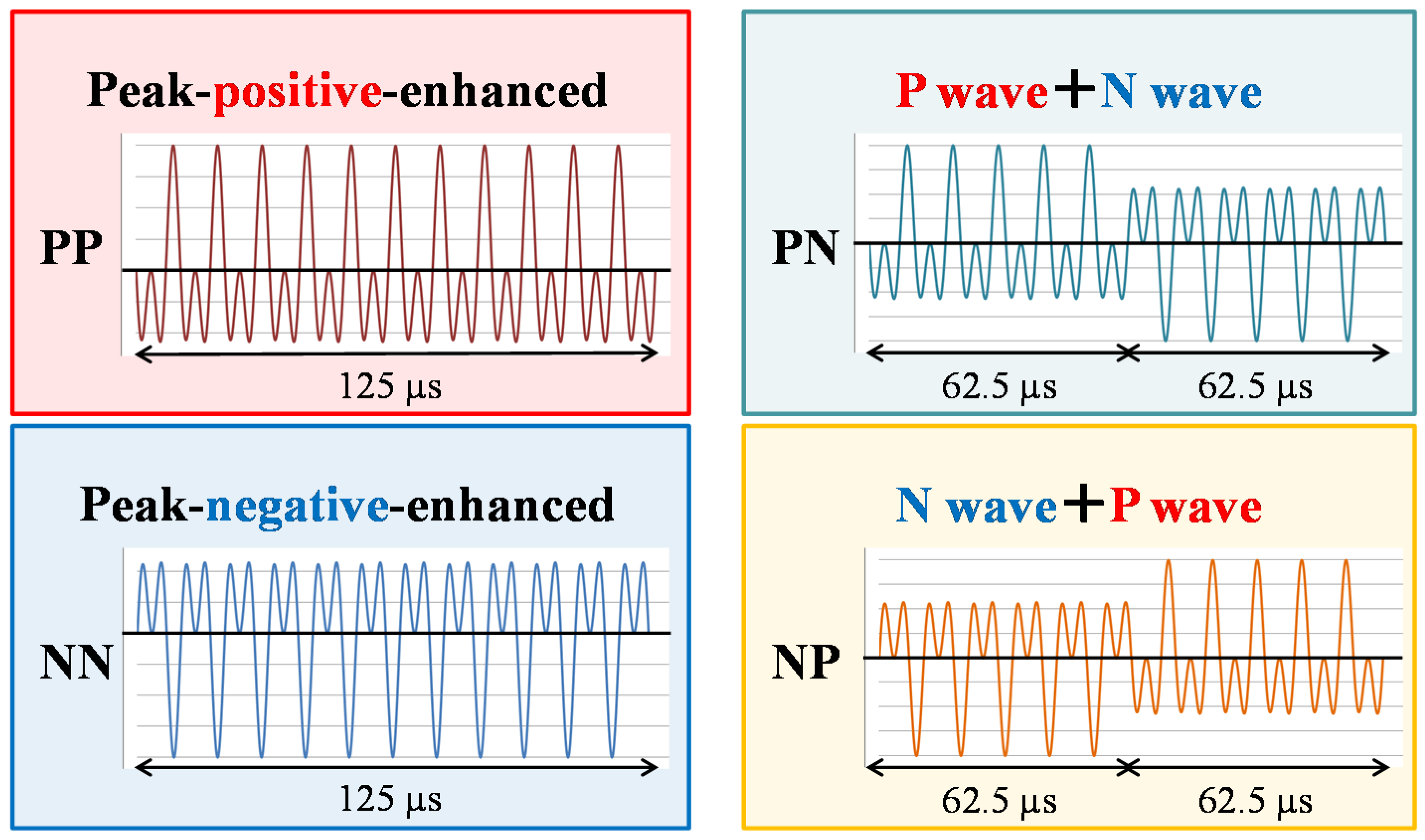
  54. Yasuda, J.; Asai, A.; Yoshizawa, S.; Umemura, S. Efficient generation of cavitation bubbles in gel phantom by ultrasound exposure with negative-followed by positive-peak-pressure-emphasized waves. Jpn. J. Appl. Phys. 2013, 52, 07HF11. [Google Scholar] [CrossRef]
  55. Chen, W.S.; Matula, T.J.; Crum, L.A. The disappearance of ultrasound contrast bubbles: Observations of bubble dissolution and cavitation nucleation. Ultrasound Med. Biol. 2002, 28, 793–803. [Google Scholar] [CrossRef]
  56. Tanter, M.; Fink, M. Ultrafast imaging in biomedical ultrasound. IEEE Trans. Ultrason. Ferroelectr. Freq. Control. 2014, 61, 102–119. [Google Scholar] [CrossRef] [PubMed]
  57. Gateau, J.; Aubry, J.F.; Pernot, M.; Fink, M.; Tanter, M. Combined passive detection and ultrafast active imaging of cavitation events induced by short pulses of high-intensity ultrasound. IEEE Trans. Ultrason. Ferroelectr. Freq. Control. 2011, 58, 517–532. [Google Scholar] [CrossRef] [PubMed]
  58. Prieur, F.; Zorgani, A.; Catheline, S.; Souchon, R.; Mestas, J.L.; Lafond, M.; Lafon, C. Observation of a cavitation cloud in tissue using correlation between ultrafast ultrasound images. IEEE Trans. Ultrason. Ferroelectr. Freq. Control. 2015, 62, 1256–1264. [Google Scholar] [CrossRef] [PubMed]
  59. Eller, A.; Flynn, H.G. Rectified diffusion during nonlinear pulsations of cavitation bubble. J. Acoust. Soc. Am. 1965, 37, 493–503. [Google Scholar] [CrossRef]
  60. Crum, L.A. Measurements of the growth of air bubbles by rectified diffusion. J. Acoust. Soc. Am. 1980, 68, 203–211. [Google Scholar] [CrossRef]
  61. Church, C.C. Prediction of rectified diffusion during nonlinear bubble pulsations at biomedical frequencies. J. Acoust. Soc. Am. 1988, 83, 2210–2217. [Google Scholar] [CrossRef] [PubMed]
  62. Bjerknes, V. Fields of Force; Colombia University Press: New York, NY, USA, 1906. [Google Scholar]
  63. Doinikov, A.A. Acoustic radiation interparticle forces in a compressible fluid. J. Fluid Mech. 2001, 444, 1–21. [Google Scholar] [CrossRef]
  64. Brennen, C.E. Fission of collapsing cavitation bubbles. J. Fluid Mech. 2002, 472, 153–166. [Google Scholar] [CrossRef]
  65. Moro, K.; Yoshizawa, S.; Umemura, S. Staircase-voltage metal–oxide–semiconductor field-effect transistor driver circuit for therapeutic ultrasound. Jpn. J. Appl. Phys. 2010, 49, 07HF02. [Google Scholar] [CrossRef]
  66. Simpson, D.H.; Chin, C.T.; Burns, P.N. Pulse inversion Doppler: A new method for detecting nonlinear echoes from microbubble contrast agents. IEEE Trans. Ultrason. Ferroelectr. Freq. Control. 1999, 46, 372–382. [Google Scholar] [CrossRef] [PubMed]
  67. Mougenot, C.; Quesson, B.; de Senneville, B.D.; de Oliveira, P.L.; Sprinkhuizen, S.; Palussière, J.; Grenier, N.; Moonen, C.T. Three-dimensional spatial and temporal temperature control with MR thermometry-guided focused ultrasound (MRgHIFU). Magn. Reson. Med. 2009, 61, 603–614. [Google Scholar] [CrossRef] [PubMed]
  68. Köhler, M.O.; Mougenot, C.; Quesson, B.; Enholm, J.; Le Bail, B.; Laurent, C.; Moonen, C.T.; Ehnholm, G.J. Improved Volumetric HIFU ablation under 3D guidance of rapid MRI thermometry. Med. Phys. 2009, 36, 3521–3535. [Google Scholar] [CrossRef] [PubMed]
  69. Enholm, J.; Kohler, M.; Quesson, B.; Mougenot, C.; Moonen, C.; Sokka, S. Improved volumetric MR-HIFU ablation by robust binary feedback control. IEEE Trans. Biomed. Eng. 2010, 57, 103–113. [Google Scholar] [CrossRef] [PubMed]
  70. Kim, Y.S.; Keserci, B.; Partanen, A.; Rhim, H.; Lim, H.K.; Park, M.J.; Köhler, M.O. Volumetric MR-HIFU ablation of uterine fibroids: Role of treatment cell size in the improvement of energy efficiency. Eur. J. Radiol. 2012, 81, 3652–3659. [Google Scholar] [CrossRef] [PubMed]
  71. Casper, A.; Liu, D.; Ebbini, E.S. Realtime control of multiple-focus phased array heating patterns based on noninvasive ultrasound thermography. IEEE Trans. Biomed. Eng. 2012, 59, 95–105. [Google Scholar] [CrossRef] [PubMed]
  72. Yoshizawa, S.; Matsuura, K.; Takagi, R.; Yamamoto, M.; Umemura, S. Detection of tissue coagulation by decorrelation of ultrasonic echo signals in cavitation-enhanced high-intensity focused ultrasound treatment. J. Ther. Ultrasound. 2016, 4, 15. [Google Scholar] [CrossRef] [PubMed]
  73. Yumita, N.; Nishigaki, R.; Umemura, K.; Umemura, S. Synergistic effect of ultrasound and hematoporphyrin on sarcoma 180. Jpn. J. Cancer Res. 1990, 81, 304–308. [Google Scholar] [CrossRef] [PubMed]
  74. Li, T.; Wang, Y.N.; Khokhlova, T.D.; D’Andrea, S.; Starr, F.; Chen, H.; McCune, J.S.; Risler, L.J.; Mashadi-Hossein, A.; Hwang, J.H. Pulsed high-intensity focused ultrasound enhances delivery of doxorubicin in a preclinical model of pancreatic cancer. Cancer Res. 2015, 75, 3738–3746. [Google Scholar] [CrossRef] [PubMed]
  75. Yasuda, J.; Miyashita, T.; Taguchi, K.; Yoshizawa, S.; Umemura, S. Quantitative assessment of reactive oxygen sonochemically generated by cavitation bubbles. Jpn. J. Appl. Phys. 2015, 54, 07HF21. [Google Scholar] [CrossRef]
  76. Yasuda, J.; Yoshizawa, S.; Umemura, S. Efficient generation of cavitation bubbles and reactive oxygen species using triggered high-intensity focused ultrasound sequence for sonodynamic treatment. Jpn. J. Appl. Phys. 2016, 55, 07KF24. [Google Scholar] [CrossRef]
Figure 1. Schematic of three examples of a trigger high-intensity focused ultrasound (HIFU) sequence with intervals for ultrasonic imaging. (a) single spot focus sequence which is typically repeated for thermal treatments; (b) spot scanning trigger pulses followed by spot scanning heating bursts; (c) spot scanning trigger pulses followed by heating bursts with a directly synthesized focus with a ring shape to cover six foci of scanned trigger pulses. The focal plane of trigger pulses in (b,c) is shifted 7 mm forward from the geometric focal plane.
Applsci 07 00288 g001aApplsci 07 00288 g001b
Figure 2. Ultrasound pressure field simulated by assuming linear propagation and neglecting attenuation. (a) without focal steering; (b) directly synthesized focus by a sector vortex method with a vortex mode number of 4.
Applsci 07 00288 g002
Figure 3. Schematics of four kinds of dual-frequency ultrasound sequences. 1.6-MHz ultrasound was superimposed onto a 0.8-MHz ultrasound to emphasize either peak positive pressure (P wave) or peak negative pressure (N wave) by adjusting the phase difference between two frequency components.
Applsci 07 00288 g003
Figure 4. High-speed images of generated cavitation bubbles in a poly(acryl amide) (PAA) gel including 22.5% bovine serum albumin (BSA) by each sequence at an ultrasound intensity of 42 kW/cm2 [54]. The frame rate was 500 kfps with an exposure time of 250 ns.
Applsci 07 00288 g004
Figure 5. High-speed images of generated and oscillating cavitation bubbles in a PAA gel including 15% BSA by the sequence shown in Figure 1a [36]. A 690-nm pulse laser with a pulse width of 20 ns was used as a backlight source.
Applsci 07 00288 g005
Figure 6. High-speed pulse inversion (PI) images with two-plane wave transmissions of a PAA gel phantom containing a 0.5% graphite layer with a thickness of 0.75 mm [36]. (a,b) PI images before and 0.9 ms after the stop of the trigger pulse exposure, respectively; (cf) difference PI images between before and 0.9 ms after the stop of the heating burst exposure with durations of 0, 1, 10, and 100 ms, respectively.
Applsci 07 00288 g006
Figure 7. High-speed images of generated and sustained cavitation bubbles in a PAA gel including 15% BSA by a sequence of spot scanning trigger pulses followed by spot scanning heating bursts which is similar to that shown in Figure 1b [34]. The instantaneous total acoustic powers of the trigger pulses and heating bursts were 1900 and 65 W, respectively. The intentional focal plane shift of the trigger pulses was not applied in this case. The same camera and light source were used as in Figure 5, except for the optical magnification.
Applsci 07 00288 g007
Figure 8. Temperature increases of a single measurement with a trigger HIFU sequence similar to that shown in Figure 1a and averaged over four measurements without trigger pulses at a lateral distance of 2.7 mm above the HIFU focus [31]. The instantaneous total acoustic powers of the trigger pulses and heating bursts were 900 and 13 W, respectively. The duration times of trigger pulses and heating bursts were 0.1 and 499.9 ms, respectively. There was no interval time for ultrasound imaging and the total duration time of HIFU exposure was 5 s.
Applsci 07 00288 g008
Figure 9. Temperature increases averaged over two measurements at the geometric focus, and 10 mm backward and 7 mm forward from it [35]. (a,c) heating bursts alone without trigger pulses and trigger HIFU sequence with spot scanning focus shown in Figure 1b, respectively; (b,d) those with a directly synthesized focus shown in Figure 1c. The total duration time of HIFU exposure was approximately 17.7 s.
Applsci 07 00288 g009
Figure 10. Average coagulation volumes of chicken breast tissues by various HIFU sequences similar to that shown in Figure 1b [33]. The total HIFU exposure was 11 s. For the trigger pulses, a single-frequency ultrasound at 0.8 MHz or dual-frequency ultrasound at 0.8 and 1.6 MHz as shown in Figure 3 with a duration time of 50 μs and acoustic intensity of 10 kW/cm2 was used. The focal points of trigger pulses were not shifted in this case. The same heating bursts were used in all sequences. The driving frequency was 1 MHz and the acoustic intensity was 1.7 kW/cm2, corresponding to an instantaneous total acoustic power of 51 W.
Applsci 07 00288 g010
Figure 11. High-speed pulse inversion images of cavitation clouds by transmitting diverging waves in chicken breast tissues during HIFU exposure [34]. The applied HIFU sequence was the same as used for the experiments shown in Figure 7 except for the focal plane shift. The total HIFU exposure time was 16.5 s. (a) the focal plane of the trigger pulses was not shifted; (b) the focal plane of the trigger pulses was shifted 10 mm forward from that of the heating bursts. In both cases, the focal plane of the heating bursts was the same as the geometric focal plane corresponding to a depth of 120 mm.
Applsci 07 00288 g011
Figure 12. Cross-sectional pictures of the coagulated chicken breast tissues. (a) the focal plane of the trigger pulses was not shifted; (b) the focal plane of the trigger pulses was shifted 10 mm forward from that of the heating bursts.
Applsci 07 00288 g012
Figure 13. Typical ultrasound images of cavitation bubbles during HIFU exposure and slices of chicken tissue samples after HIFU exposure [35]. Heating bursts with spot scanning and direct synthesis were exposed for (ah), respectively. Trigger HIFU sequences shown in Figure 1b,c were used for (ac,eg), respectively; (a,d) variance images of high-speed pulse inversion data by transmitting diverging waves; (b,f) the gross pathology in the longitudinal cross section; (c,g) the gross pathology in the lateral cross section; and (d,h) the gross pathology in the longitudinal cross section without trigger pulses.
Applsci 07 00288 g013
Figure 14. Ultrasonically detected cloud size and the coagulation area size [35]. (a) spot scanning; (b) direct synthesis.
Applsci 07 00288 g014
Table 1. Example of combination of beamforming technics for trigger high-intensity focused ultrasound (HIFU) sequence.
Corresponding Sequence in Figure 1Trigger PulseHeating Burst
Spot Scanning FocusFocal Plane ShiftSpot Scanning FocusWide Focus
Figure 1a
Figure 1b
Figure 1c
Table 2. Thickness of intermediate brightness regions at the ends of a coagulation region in a chicken breast tissue without and with the focal plane shift of trigger pulses [34].
Trigger Pulse Focal Shift (mm)Thickness of Intermediate Brightness Region at the Backward End of Coagulation Region (mm)Thickness of Intermediate Brightness Region at the Forward End of Coagulation Region (mm)
05.656.30
104.252.95

