
Influence of Welding Parameters on the Weld Pool Dimensions and Shape in a TIG Configuration


LAPLACE, Université de Toulouse, CNRS, INPT, UPS 118 rte de Narbonne, 31062 Toulouse CEDEX, France
*
Author to whom correspondence should be addressed.
Appl. Sci. 2017, 7(4), 373; https://doi.org/10.3390/app7040373
Submission received: 24 February 2017
/
Revised: 31 March 2017
/
Accepted: 5 April 2017
/
Published: 8 April 2017
(This article belongs to the Special Issue Gas Tungsten Arc Welding)
Abstract
:The weld pool shape created by the plasma arc interaction on a workpiece depends on many geometrical and physical parameters and on the operating conditions. Theoretical models are developed in such a way as to predict and to characterize the material. However, these models first need to be validated. Experimental results are hence proposed with parametric studies. Nevertheless, the interaction time is often short and the weld pool shape evolution not presented. In this work, the experimental setup and the diagnostic methods characterizing the workpiece are presented. The weld pool shape was evaluated versus time according to several parameters such as the current intensity value, the distance between the two electrodes, the cathode tip angle or the plasma gas nature. The results show that the depth-to-width ratio alone is not enough to compare the impact of the parameters. The analysis points out the great influence of the current intensity on the increase of the width and depth compared to the influence of the value of the cathode tip angle. The rise of the arc length leads to an increase of the power through a higher arc voltage; nevertheless, for distances of three and five millimeters and a characteristic time of the welding process of one second, this parameter has a weak influence on the energy transferred. The use of helium leads to a bigger volume of the weld pool due to an increase of width and depth.
1. Introduction
In tungsten inert gas (TIG) welding, an electric arc is created between a tungsten electrode and a piece of metal. The energy transferred to the metal leads to a molten pool and to the production of metallic vapours. A shielding gas is injected to protect the weld pool from contamination. Effects of the welding parameters on the shape and on the energy transferred to the workpiece are often studied to improve the knowledge of plasma–material interaction in the process [1,2,3,4,5]. Numerous experimental conditions are involved in the TIG process, such as the nature of the shielding gas, the current intensity value, the torch velocity, the volume flow rate and geometrical parameters, such as the distance between the two electrodes or the cathode tip angle. In this paper, the study is focused on the welding current intensity, the arc length, the nature of the shielding gas and the tip angle of the cathode.
According to published works, the increase of welding current leads to a higher and wider radial spread of the heat flux density at the surface of the material [6,7,8]. Nevertheless, different behaviours are observed: a linear rise of the heat flux density as a function of the current intensity between 100 A and 300 A is found [9], whereas stagnation is observed by other authors [10]. It is possible that other parameters such as the arc length or the tip angle of the cathode are involved in these differences. Regarding the effect of the current intensity on the weld pool shape, drawing a conclusion is difficult: increasing the welding current modifies the balance between the forces applied to the molten pool and affects the weld pool shape in a non-intuitive way [11].
The rise of the arc length leads to an increase of the applied power through a higher arc voltage. Nevertheless, arc length has a weak influence on the energy transferred to the workpiece: a decrease of the maximum heat flux density and a wider radial spread are observed [9]. The longer the arc is, the faster the velocity in the plasma is and so the higher the shear forces are. The effect of these forces becomes predominant among the others when the arc length is up to eight millimeters. Conversely, for short arcs (less than three millimeters), the weld pool becomes deeper [11].
Changing the nature of the shielding gas modifies the arc voltage and therefore the applied power. The use of argon with an addition of helium, hydrogen or oxygen leads to an increase of the maximum density of the heat flux without affecting the radial spread. This leads to a higher energy transferred to the material [12]. Moreover, using helium instead of argon shows a significant increase of the weld pool depth [13,14].
The rise of the tip angle reduces the arc voltage and therefore the applied power [15,16]. For a given arc length, increasing the tip angle leads to a weaker maximum of the heat flux density and to a wider radial spread. Otherwise, the heat flux density is maximal for a 60° tip angle and is more significant for a short arc length (roughly two millimeters) [17]. Regarding its influence on the weld pool shape, some authors point out a loss of penetration when the tip angle increases, whereas others see no effect [18].
Analysis of published works shows the great interest in studying the influence of operating conditions on the weld for a better understanding of the phenomenon involved in the plasma–material interaction and for an optimisation of the TIG process. However, disparity in operating parameters and their dependence leads sometimes to opposite effects.
The aims of the paper were to contribute to the improvement of knowledge of the pool behaviour and to study the influence of some parameters on its shape. Four parameters are studied (welding current, arc length, nature of the shielding gas and tip angle of the cathode) on the weld pool for six times of interaction (1, 4, 8, 12, 16, 20 s). The influence of these parameters is evaluated through comparison of the weld pool width, depth, shape and the energy involved.
2. Experimental Procedure
2.1. Experimental Setup
The experiments were performed with an ESAB TIG torch BTE250M (Figure 1) and an MIG U5000i welding generator operating in current regulation mode and in direct polarity.
The electric arc is initiated between a 1.5% lanthanated tungsten cathode and a piece of AISI 304L stainless steel (anode). The cathode diameter is 3.2 mm and the shielding gas is injected around it with a volume flow rate of 10 L/min. The anode is a cylinder of 50 mm diameter and 10 mm height placed on a copper support (no water cooling). This support has no effect on the evolution of the weld pool depth [19]. The sulphur content of the anode has been evaluated to 300 ppm [19].
The torch is used in a static mode (spot TIG) in vertical position without inclination. Effects of the following parameters are studied: welding current, arc length, nature of the shielding gas, cathode tip angle. The experiments were conducted by keeping all welding parameters constant except the one investigated (Figure 2a).
A high-speed camera (Photron Fastcam SA5, San Diego, CA, USA) is used to observe the weld pool changes during the interaction. This camera is able to reach 1 million frames per second (fps) and 7500 fps with full resolution. Its CMOS sensor contains 1024 × 1024 pixels of 20 μm. The exposure time is set to 50 μs and 10,000 fps are recorded. A 105 mm focal length lens (Sigma Macro, Ronkonkoma, NY, USA) is mounted on the camera. The camera is placed 25 cm away from the weld pool with an inclination angle of 30° providing a resolution of 21 μm in the horizontal direction of the image and 100 μm in the vertical one.
The applied power is evaluated with voltage and current intensity measurements. The time reference (t = 0) fits with the arc ignition. Recordings start through a photo diode which collects the flash emitted by the arc at ignition via an optical fibre (Figure 2b). Devices are plugged to a pulse generator which allows synchronizing the acquisitions of the voltage, the current intensity and the high speed camera.
2.2. Data Treatment
The weld pool dimensions and shape are determined for six interaction times (1, 4, 8, 12, 16 and 20 s) using three methods [1].
- Method 1 is based on high speed videos. During the arc interaction, images of the weld pool are recorded every one or two seconds. The diameter of the weld pool is evaluated for each sequence of images.
- Method 2 enables the estimating of the weld pool width from pictures of the top surface of the anode at the final instant.
- Method 3 consists in analysing the internal dimensions of the weld pool and the melted zone shape with metallographic investigation. After cutting and polishing the anodes, a 45 s FeCl3 attack is led to reveal the grain of the welded area. Microscopy determines the width, the depth and the shape of the weld pool.
The three methods are illustrated in a previous work [1] for Arcal.37 plasma after 8 s of interaction with a current intensity I = 100 A, a tip angle θ = 60°, a distance between cathode and workpiece L = 5 mm.
3. Results
We are interested in studying the influence of four parameters: the gas nature, the value of the current intensity, the distance between the workpiece and the cathode and the value of the cathode tip angle. For each parameter two values are considered:
- Intensity: I = 100 A and I = 150 A
- Distance: distances between the cathode tip and the workpiece d = 3 mm and d = 5 mm.
- Tip angle: Θ = 30° and Θ = 60°
- Gas: Helium and Arcal.37. The two gases are commercial products from Air Liquid Company. Arcal.37 designates a mixture of 30% of argon and 70% of helium.
Many combinations of these parameters are possible. Sixteen cases should be considered in the experimental plan. We have chosen to replicate each experimental case three times to test the reproducibility. We would also like to analyse the weld pool shape versus time considering six durations.
Due to the important number of cases to consider we decide to limit the experimental plan. The study mainly focuses on the first three parameters with two additional cases with Helium gas. The cases considered are presented Table 1 and conducted from 1 to 20 s in 4-s steps.
Table 2 details and provides the associated numerical values of the weld pool dimensions for each case. The given values thus correspond to mean values. Method 2 is based on the analysis of one picture at the final time, so to obtain the width dimensions for each given time, six experiments are necessary when only one experiment is necessary for method 1. In order not to multiply the number of experiments only method 1 is used for cases 5, 6 and 7. However at the end of the experiment the material is analyzed using method 3 and the widths and depths determined by metallographic investigations. So, some data is available for methods 2 and 3 from cases 5, 6 and 7.
Measurements of voltage and current intensity enable an estimation of the applied energy (Eapplied) during the interaction. Measurements of voltage and current intensity are also used to estimate the applied energy (Eapplied) during the interaction.
The volume of the melted area and the energy involved to fuse this amount of metal (Efusion) are evaluated from the weld pool shape, considered as axisymmetric,
where Cp is the specific heat, Lf the latent heat involved in the transition between solid and liquid state and m the mass of melted metal. The melting point of the AISI 304L is Tmel = 1724 K and the boiling point Tboil = 3134 K. It is difficult to estimate the evaporated part of the material from the melting to the boiling temperature, so to calculate the energy devoted to the fusion one intermediate temperature of Tint = 2400 K is used for this calculation [1].
The ratio between Efusion and Eapplied leads to an indication of the efficiency (γ) of the experimental parameters. Their values are indexed in Table 3.
4. Discussion
In this section, effects of four welding parameters described in paragraph 1 are presented and discussed: (1) the welding current; (2) the arc length; (3) the nature of the shielding gas and (4) the cathode tip angle.
4.1. Effect of the Welding Current
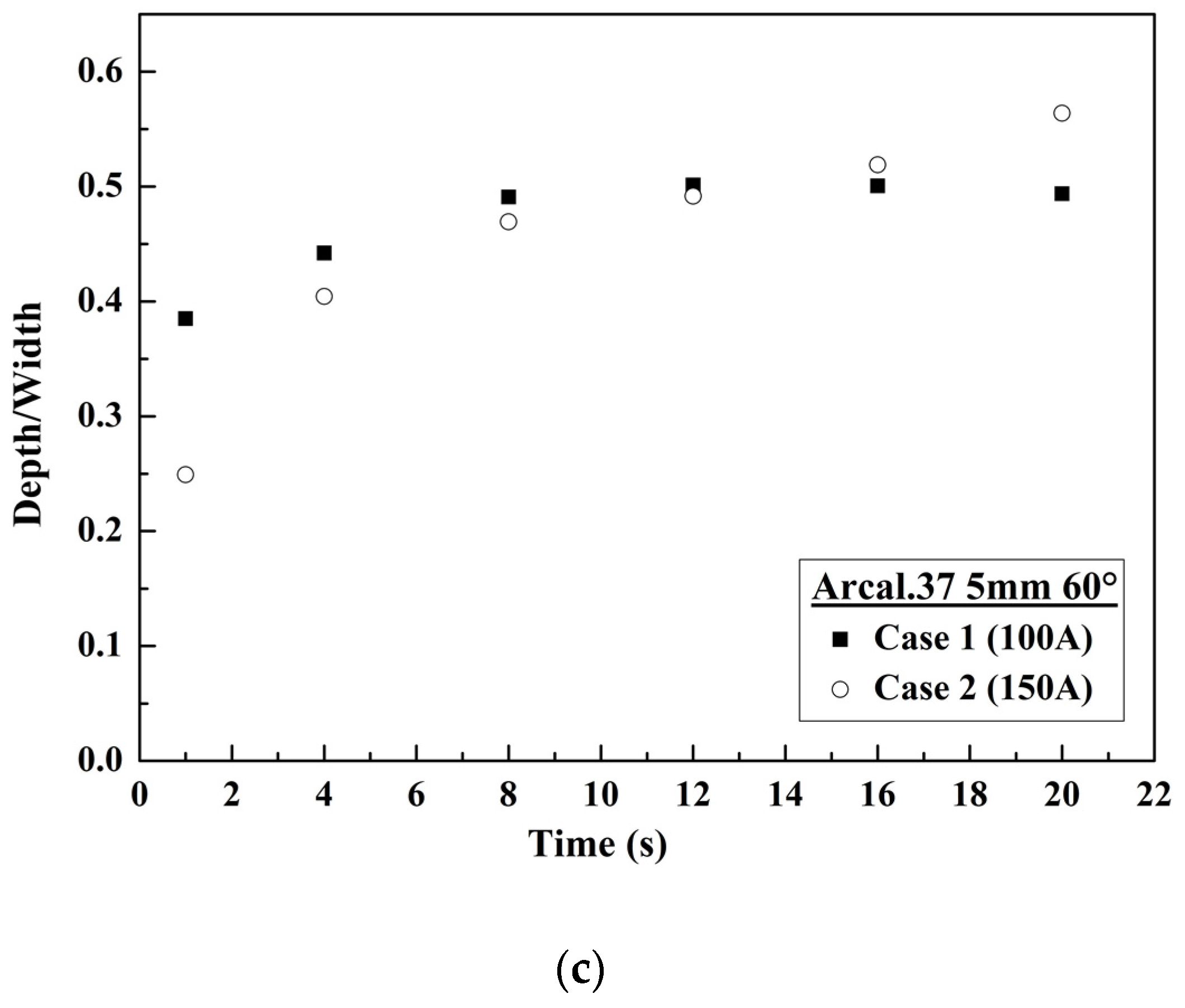
To study the effect of the current intensity, cases n°1 (I = 100 A) and n°2 (I = 150 A) are compared. Figure 3a displays the weld pool width evolution from 1 to 20 s of interaction, involving Arcal.37, an arc length L = 5 mm and a tip angle θ = 60°.
Values estimated by the three methods are consistent in both cases. Diameters evaluated in case n°2 are notably wider whatever the time of interaction. The expansion of the weld pool has a similar behaviour for the two current intensity values. A rapid increase of the weld pool dimensions during the two first seconds is observed followed by a slow expansion. This variation can be explained by two mechanisms: during the first instants, the weld pool width is a result of to the electrical flux components, then of the heat flux diffusion in the material. In case of a higher current intensity value, the current density distribution is enlarged and the welds pool width larger. This conclusion needs to be balanced depending on the distance between the cathode and the workpiece. The main difference obtained during the two first seconds is then conserved for up to 20 s. The comparison of the weld pool shapes for the two cases (n°1 and n°2) from 1 to 20 s is presented Figure 3b.
The weld pool gets deeper with time for the higher welding current due to the higher flux transferred to the material. A stagnation of the weld pool depth is observed from time t = 12 s with a current of 100 A (case n°1), whereas the depth keeps increasing with an intensity of 150 A (case n°2). Maximal width reaches 10.5 ± 0.02 mm (respectively 8.00 ± 0.02 mm) and maximal depth reaches 5.92 ± 0.02 mm (respectively 3.95 ± 0.02 mm) in case n°2 (respectively case n°1) at time t = 20 s. We have performed the same experiments, changing the workpiece dimensions, in order to verify that the stagnation of the isotherms propagation was not due to natural anode cooling. If we observe the widths for the first measure (t = 1 s) we note 4 mm and 6 mm respectively for 100 A and 150 A. The stagnation is then observed at 8 mm and 10.4 mm for respectively 100 A and 150 A. In case n°2 from t = 1 s to 20 s the width is 2 mm greater than in case n°1. This behaviour must be due to the curve of diffusivity [1] which presents a minimum for temperatures higher than 1000 K. Figure 3c describes the evolution of depth-to-width ratio.
A stabilization of this ratio is observed in case n°1 around 0.50, while it increases in case n°2. In these configurations, the rise of the welding current leads to a predominance of the digging forces (Marangoni, Lorentz and pressure forces) driving to a deeper weld pool. The stabilization of the ratio in case n°1 is due to a stagnation of the weld pool depth observed Figure 3b. The heat flux profile is wider in case n°2, so the width is greater and the initial ratio lower than at I = 100 A. Then, due to the stagnation of the depth in case n°1, we can observe an intersection between the two evolution profiles.
4.2. Effect of the Arc Length
The effect of the arc length is made through the comparison of case n°1 (five millimeters) and case n°3 (three millimeters). Figure 4a describes the weld pool width evolution from 1 to 20 s of interaction in Arcal.37 with a welding current of 100 A.
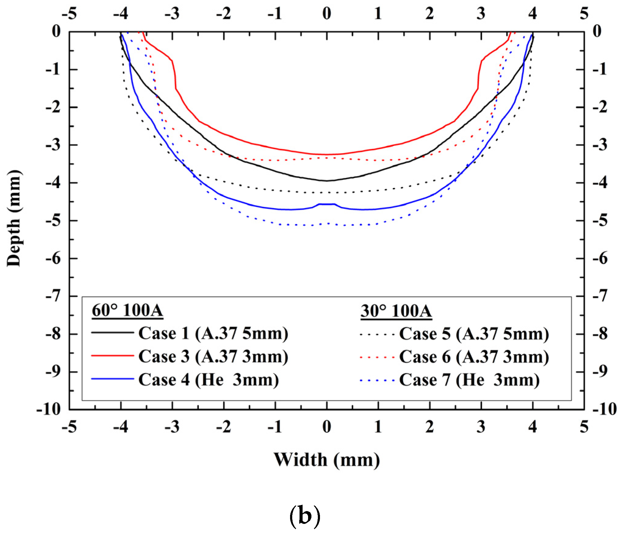
The weld pool expands in the same way as described above. The stabilization of the weld pool width happens after 8 s in case n°3, against 12 s for case n°1. Values of the weld pool width are slightly higher in case n°1, especially after 8 s of interaction. Figure 4b displays the weld pool shapes for both cases from 1 to 20 s.
Comparison of these profiles shows that the melted area is modified by the decrease of the arc length. While the weld pool shape looks like a ‘bowl’ in case n°1, some bulges appear on both sides of the profile in case n°3. The weld pool depth is more important as the arc length increases. Due to a higher distance between the cathode tip and the anode material, the drop voltage increases, leading to an augmentation of the applied power. In the same time the width increases, leading to a bigger weld pool. A stagnation of the weld pool depth is observed in both cases. Maximal width reaches 8.00 ± 0.02 mm (respectively 7.16 ± 0.02 mm) and maximal depth reaches 3.95 ± 0.02 mm (respectively 3.40 ± 0.02 mm) in case n°1 (respectively case n°3). Figure 4c presents the evolution of depth-to-width ratio. This ratio evolution is almost the same in the two cases with stabilization around 0.50.
In these configurations, one diminution of the arc length modifies the balance of the different forces. As mentioned in Introduction, an increase the arc length would lead to a rise of the shear forces resulting in a wider weld pool, and to a rise of the pressure forces leading to a deeper weld pool [9]. Our experimental work is consistent with those reports: wider and deeper pools are observed for the longer arc. It is interesting to note that up to 12 s the weld pool area remains almost the same. The evolution of the front of fusion given in Figure 4c can be interpreted by the curve of the diffusivity versus temperature Figure 4d. During the first second, the material is not heated much by the flux components and the diffusivity takes place at low temperature. Thus, the ‘mean’ diffusivity is very high and the position of the front of fusion changes rapidly. Then progressively the workpiece is heated, leading to a diminution of the diffusivity. We can assume that from time t = 12 s the temperature is higher than 1000 K and that the diffusivity is low, leading to a weak evolution of the shape of the weld pool.
4.3. Effect of the Nature of the Shielding Gas
Case n°3 (Arcal.37) and case n°4 (He) allow the study of the influence of the nature of the shielding gas. Figure 5a describes the weld pool width evolution from 1 to 20 s in the case of the interaction of a three-millimeter Arcal.37 and a three-millimeter helium plasma with a welding current of 100 A.
The expansion of the weld pool retains the same behaviour. Diameters evaluated in case n°4 (Helium gas) are wider but the main difference is with the depths. The comparison of the weld pool shapes for both cases from 1 to 20 s is presented Figure 5b.
Analysis of these profiles shows that the fusion shape changes with the shielding gas. Bulges observed in case n°3 disappear in case n°4. The weld pool depth is significantly higher with the use of helium. A stagnation of the depth is observed in case n°3 whereas the depth keeps rising in case n°4. Maximal width reaches 7.94 ± 0.02 mm (respectively 7.16 ± 0.02 mm) and maximal depth gets to 4.57 ± 0.02 mm (respectively 3.40 ± 0.02 mm) in case n°4 (respectively case n°3).
In gas mixtures containing helium, such as Arcal.37, the resulting drop voltage for the same current intensity is higher than in pure Ar [20]. Thus, we can assume that for the same current intensity I = 100 A and the same distance between the two electrodes (L = 3 mm), the applied energy is higher in pure helium than in Arcal.37 gas, where the helium proportion is lower leading to a higher flux transfer. The depth evolution in pure helium is therefore greater, even at t = 1 s.
Figure 5c describes the evolution of depth-to-width ratio. A stabilization of this ratio is observed in case n°3 around 0.5, while it keeps increasing in case n°4. In these configurations, changing the nature of the shielding gas leads to deeper welds. For the same configuration, helium plasma created a more energetic environment than Arcal.37 plasma.
The weld pool surface temperature distribution is thus different and the direction of Marangoni forces is modified [21]. This leads to an inward flow resulting in a deeper weld pool. Moreover, movements resulting from the Lorentz forces increase. Some studies showed that the maximal velocity of the flow due to Lorentz forces rises when helium is used instead of argon [13]. The ratio between the energy used to fuse the volume of metal (Efusion) and the energy involved in the process (Eapplied) is given in Figure 5d. A diminution of this ratio with time is observed in both cases with values slightly higher in case n°4. This indicates that the radiation, conduction or evaporation losses are less significant with the use of helium. The process would therefore be more efficient in case n°4 (He). The nature of the shielding gas is a fairly significant parameter on the weld dimensions and on the process efficiency.
4.4. Effect of the Cathode Tip Angle
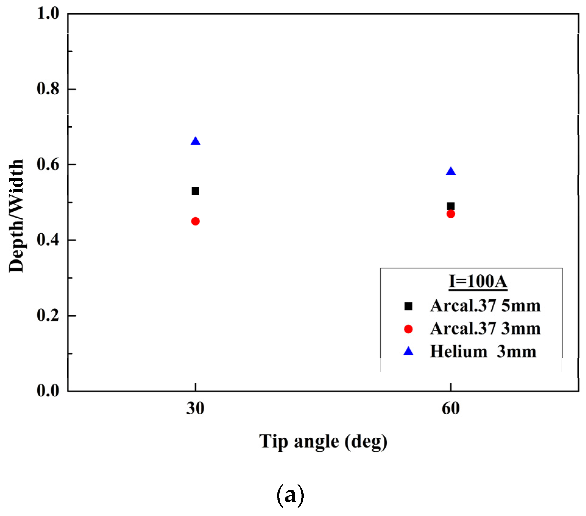
To study the effect of the cathode tip angle, Arcal.37 gas: Cases n° 1 and n°5, n°3 and n°6 and helium gas: Cases n°4 and n°7 are considered. Figure 6 displays the weld pool width evolution for L = 5 mm in Arcal.37 plasma (Figure 6a), L = 3 mm in Arcal.37 plasma (Figure 6b) and L = 3 mm in helium plasma (Figure 6c) for θ = 30° and θ = 60° cathode tip angle from 1 to 20 s.
In the case of Arcal.37, the mean values of the weld pool width, estimated with the three methods, are little impacted with the changes of the cathode tip angle, as a difference of 0.23 mm (respectively 0.35 mm) is noticed for an arc length of five millimeters (respectively three millimeters) after 20 s of interaction when the cathode tip is reduced. These differences are in the range of the uncertainties so it is difficult to conclude that this parameter has a significant influence. For the helium plasma, values are more impacted as a difference of almost one millimeter is observed between the two cathode tip angle values. Using a smaller angle value of the cathode tip leads to a wider weld pool.
The mathematical models [17,22] proposed by Goodarzi et al. deal with this point. The authors indicate [17,22] that by decreasing the electrode tip angle the anode spot at the weld pool surface tended to be flatter, leading to a smaller heat flux and anode current density, that the gas shear stress increased due to gas flow, and that the two effects led to a wider weld pool. The study was made for an interaction time of two seconds and for cathode tip angles in the range 9.18° to 131.41°. The theoretical shapes presented by the authors for 28.36° and 60° in case of an arc length of five millimeters differed by only 0.2 mm when applying a current intensity of I = 200 A. Only this interaction time was presented in the paper [22]. The main differences in our cases are from 2 s up to 20 s. Our experimental width evolutions during the first second for the two angles are included in the error bars and weak differences appear. Nevertheless, from 2 s up to 20 s our conclusion is consistent with the behaviour found by Goodarzi et al. Other theoretical results exist on the influence of the value of the cathode tip angles, such as for instance the paper presented by Abid et al. [23], however in those cases the torch position is not vertical (70°) and the model is stationary.
Figure 7a presents the depth-to-width ratio for two cathode tip angles. The ratio decreases when the tip angle increases in helium and L = 5 mm in Arcal.37 plasma. In reality, if we observe Figure 7b the weld pool shapes after t = 20 s of interaction, the widths are weakly modified, the changes having been in the weld pool areas and in the depths.
Due to the decrease of the cathode tip angle, the depth-to-width ratio increases as the depths increase. Theoretical study [20] has shown, adapting the intensity to assume the same power for a given distance between the electrodes, that the heat flux transferred to the material was greater using helium. Changing the distance from L = 3 mm to L = 5 mm in Arcal.37 does not allow compensation of the energy transferred in the helium case for the same value of the current intensity.
5. Conclusions
In the literature models, the arc ignition is not considered and the numerical procedure to initiate the arc is not often described. The description of the interaction with the workpiece during the first instants is therefore subject to discussion. The results of the mathematical models need therefore to be considered carefully during the first instants and it should be better for model validation to consider longer times. For these reasons and due to the lack of experimental values, our experiments were realized from 1 s to 20 s. In a vertical TIG configuration, effects of different welding parameters were analysed through the weld pool dimensions, shape and through energy involved to melt the material. Six interaction times were considered. For each interaction time, three methods were applied to determine the weld pool dimensions.
Our analysis pointed out that the welding current is the more influential parameter, as width and depth rise significantly when it increases. Increasing the arc length modifies both the shape and dimensions: width and depth of the weld pool are higher. Use of helium as a shielding gas instead of Arcal.37 leads to a deeper weld pool but the shape remains the same. These effects are explained by the predominance of penetrating movements, which become higher when energetic plasma such as helium is used. Finally, modification of the tip angle affects the weld pool dimensions, especially in depth, which is greater when the tip angle decreases. Nevertheless, this parameter appears less significant than other parameters studied.
The melted area shapes and their related energy, and not only the depth-to-width ratio, appear essential to study the influence of welding parameters. All these experimental data and observations are obtained in a vertical TIG position without movement. Even if this configuration can be considered ‘simple’ compared to the real welding process, these experimental results are essential and can be used for comparisons and model validation in simple 2D configuration before considering a transient 3D configuration.
Acknowledgments
The authors would like to thanks here ESAB Company and I. Choquet from West University of Sweden for their contribution on this work.
Author Contributions
Marine Stadler conducted the experiments, analyzed the data and proposed the plan of the paper. Jean–Jacques Gonzalez and Pierre Freton analyzed the data, write the paper and proofread it.
Conflicts of Interest
The authors declare no conflict of interest.
References
- Stadler, M.; Masquère, M.; Freton, P.; Gonzalez, J.J. Experimental Characterization of the weld pool expansion in a Tungsten Inert Gas Configuration. J. Sci. Technol. Weld. Join. 2017, 22, 319–326. [Google Scholar] [CrossRef]
- Burgardt, P.; Heiple, C.R. Interaction between impurities and welding variables in determining GTA weld shape. Weld. Res. Suppl. 1986, 65, 150. [Google Scholar]
- Shirali, A.A.; Mills, K.C. Effects of welding parameters on penetration in GTA welds. Weld. Res. Suppl. 1993, 72, 347-s–353-s. [Google Scholar]
- Mills, K.C.; Keene, B.J. Factors affecting variable weld penetration. Int. Mater. Rev. 1990, 35, 185–216. [Google Scholar] [CrossRef]
- Murphy, A.B. A Perspective on Arc Welding Research: The Importance of the Arc, Unresolved Questions and Future Directions. Plasma Chem. Plasma Process. 2015, 35, 471–489. [Google Scholar] [CrossRef]
- Tsai, N. Heat Distribution and Weld Bead Geometry in Arc Welding. Ph.D. Thesis, Massachussetts Institute of Technology, Cambridge, MA, USA, 1983. [Google Scholar]
- Vilarinho, L.O.; Fanara, C. A modified split-anode detector for the study of the anode region of atmospheric pressure arc plasmas. Meas. Sci. Technol. 2003, 15, 67–74. [Google Scholar] [CrossRef]
- Gonzalez, J.J.; Freton, P.; Masquère, M. Experimental quantification in thermal plasma medium of the heat flux transferred to an anode material. J. Phys. D Appl. Phys. 2007, 40, 5602–5611. [Google Scholar] [CrossRef]
- Tsai, N.; Eagar, T. Distribution of the heat and current fluxes in gas tungsten arcs. Metall. Trans. B 1985, 16, 841–846. [Google Scholar] [CrossRef]
- Nestor, O. Heat intensity and current density distributions at the anode of high current, inert gas arcs. J. Appl. Phys. 1962, 33, 1638–1648. [Google Scholar] [CrossRef]
- Brochard, M. Modèle Couple Cathode-Plasma-Pièce en vue de la Simulation du Procédé de Soudage à l’arc TIG. Ph.D. Thesis, Université de Provence, Aix-Marseille, Provence, France, 2009. [Google Scholar]
- Murphy, A.B.; Tanaka, M.; Yamamoto, K.; Tashiro, S.; Lowke, J.J.; Ostrikov, K. Modelling of arc welding: The importance of including the arc plasma in the computational domain. Vacuum 2010, 85, 579–584. [Google Scholar] [CrossRef]
- Tanaka, M.; Lowke, J.J. Predictions of weld pool profiles using plasma physics. J. Appl. Phys. D Appl. Phys. 2007, 40, R1. [Google Scholar] [CrossRef]
- Tanaka, M.; Tashiro, S.; Satoh, T.; Murphy, A.B.; Lowke, J.J. Influence of shielding gas composition on arc properties in TIG welding. Sci. Technol. Weld. Join. 2008, 13, 225–231. [Google Scholar] [CrossRef]
- Key, J. Anode/Cathode Geometry and Shielding Gas Interrelationships in GTAW. Weld. J. 1980, 59, 364-s–370-s. [Google Scholar]
- Egerland, S.; Colegrove, P.; Williams, S. Investigation of low current gas tungsten arc welding using split anode calorimetry. Sci. Technol. Weld. Join. 2016, 22, 71–78. [Google Scholar] [CrossRef]
- Goodarzi, M.; Roland, C.; Tomio, T.; Toguri, J.M. The effect of the cathode tip angle on the gas tungsten arc welding arc and weld pool: II. The mathematical model for the weld pool. J. Phys. D. Appl. Phys. 1998, 31, 569–583. [Google Scholar] [CrossRef]
- Perry, N. Étude et Développement des Flux Solides en vue D’application en Soudage ATIG Appliqué au Titane et ses Alliages Ainsi qu’aux Aciers Inoxydables. Ph.D. Thesis, Ecole Centrale de Nantes, Nantes, France, 2000. [Google Scholar]
- Stadler, M. Etude Expérimentale du Mouvement Hydrodynamique d’un Bain Metallique et de sa Production de Vapeurs sur une Configuration de Sousage TIG. Ph.D. Thesis, Université Toulouse 3, Toulouse, France, 2016. [Google Scholar]
- Mougenot, J. Modélisation de L’interaction Entre un arc Electrique et Matériau: Application au Soudage. Ph.D. Thesis, Université Toulouse 3, Toulouse, France, 2013. [Google Scholar]
- Mills, K.C.; Keene, B.J.; Brooks, R.F.; Shirali, A. Marangoni effects in welding. Philos. Trans. R. Soc. Lond. Ser. A Math. Phys. Eng. Sci. 1998, 356, 911–926. [Google Scholar] [CrossRef]
- Goodarzi, M.; Roland, C.; Tomio, T.; Toguri, J.M. The effect of the electrode tip angle on the gas tungsten arc welding arc and weld pool: I. Mathematical model of the arc. J. Phys. D. Appl. Phys. 1977, 30, 2744–2756. [Google Scholar] [CrossRef]
- Abid, M.; Parvez, S.; Nash, D.H. Effect of different electrode tip angles with tilted torch in stationary gas tungsten arc welding: A 3D simulation. Int. J. Press. Vessels Pip. 2013, 108–109, 51–60. [Google Scholar] [CrossRef]
Figure 1.
Tungsten inert gas (TIG) welding device.

Figure 2.
(a) Illustration of the experimental setup detail of the torch elements and welding parameters; (b) Illustration of the experimental setup synchronization system.
Figure 2.
(a) Illustration of the experimental setup detail of the torch elements and welding parameters; (b) Illustration of the experimental setup synchronization system.
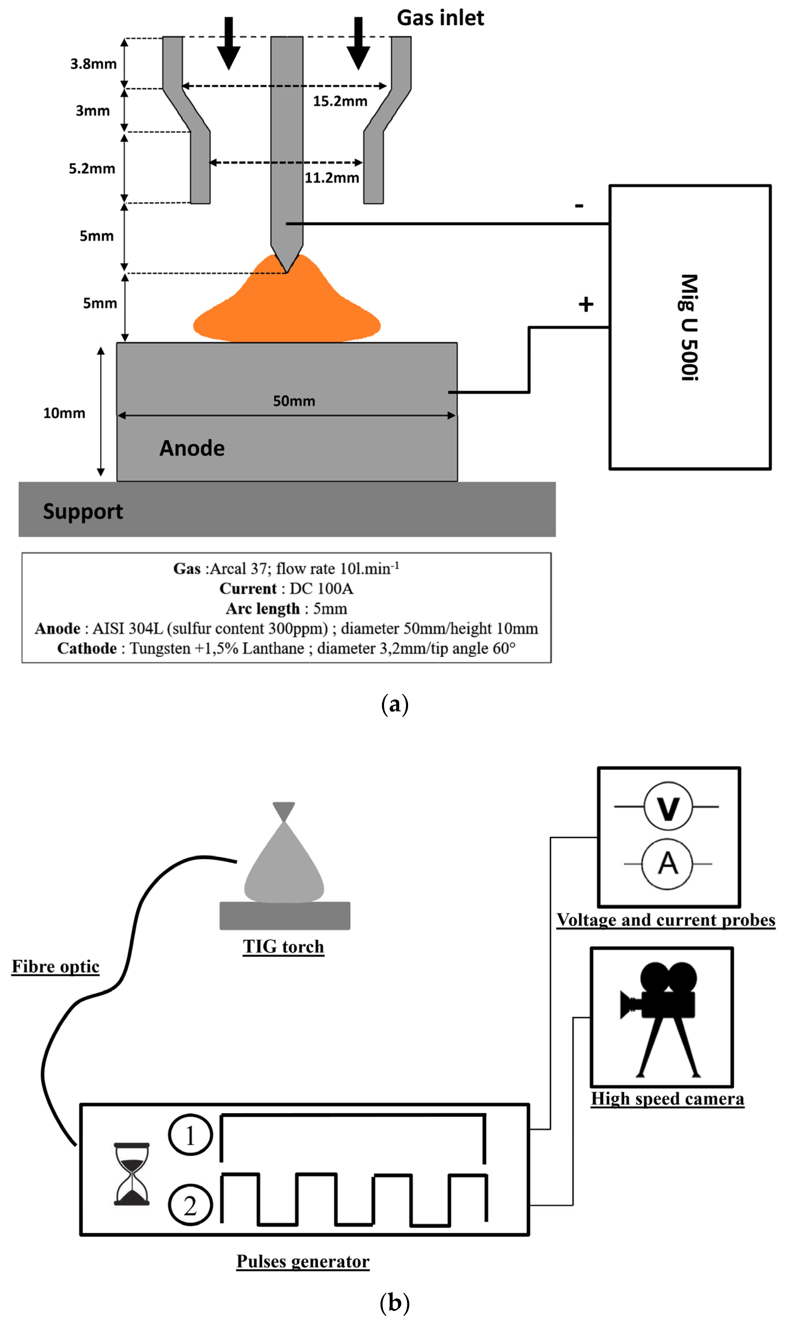
Figure 3.
(a) Effect of the current intensity on the evolution of the weld pool width; (b) Effect of the current intensity on the evolution of the weld pool shapes; (c) Effect of the current intensity on the depth-to-width ratio.
Figure 3.
(a) Effect of the current intensity on the evolution of the weld pool width; (b) Effect of the current intensity on the evolution of the weld pool shapes; (c) Effect of the current intensity on the depth-to-width ratio.
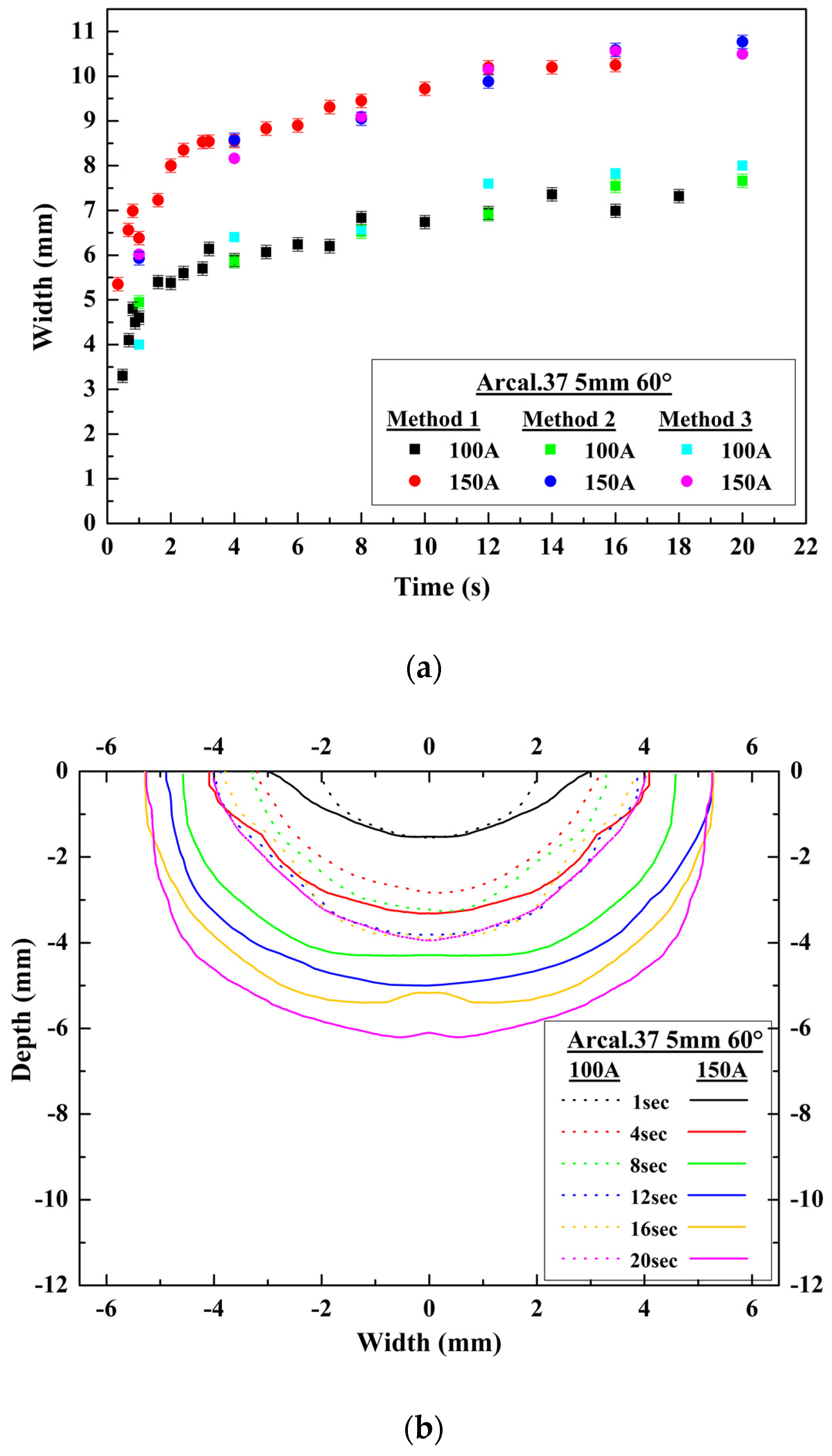

Figure 4.
(a) Effect of the arc length on the evolution of the weld pool width; (b) Effect of the arc length on the evolution of the weld pool shapes; (c) Effect of the arc length on the depth-to-width ratio; (d) Mechanism of the weld pool expansion: thermal diffusivity.
Figure 4.
(a) Effect of the arc length on the evolution of the weld pool width; (b) Effect of the arc length on the evolution of the weld pool shapes; (c) Effect of the arc length on the depth-to-width ratio; (d) Mechanism of the weld pool expansion: thermal diffusivity.
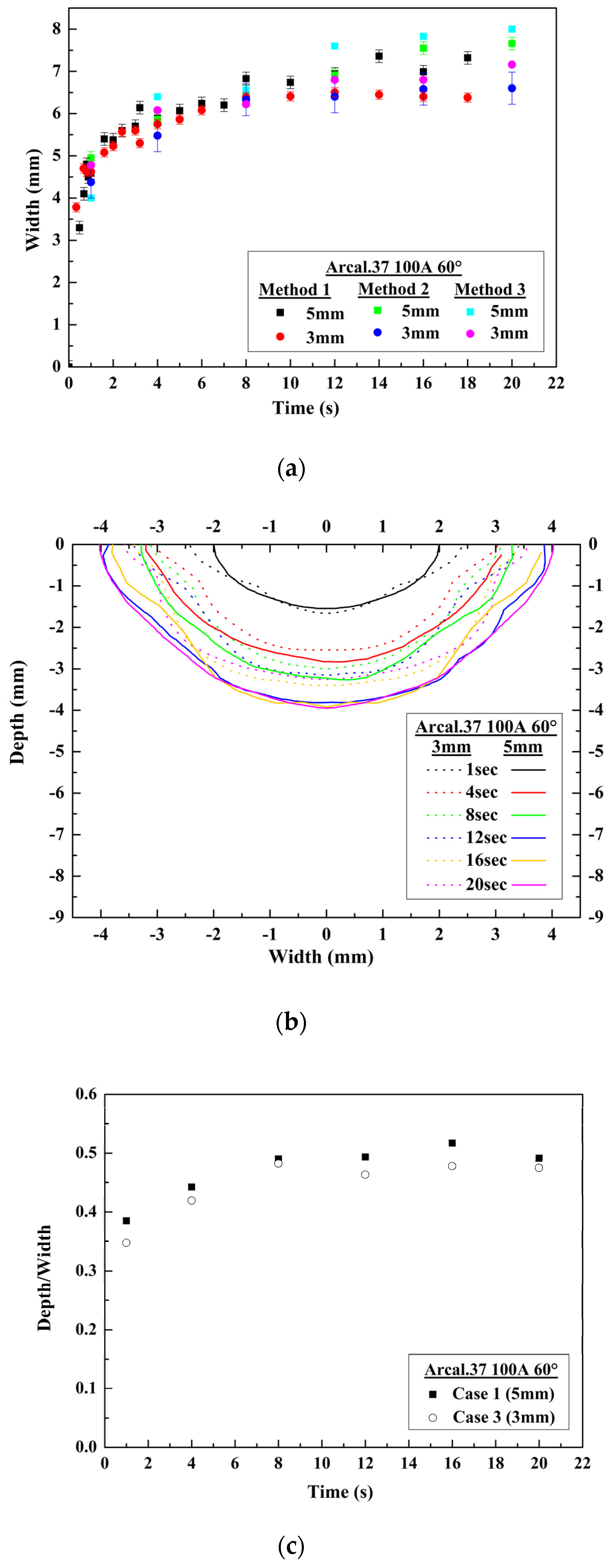

Figure 5.
(a) Effect of the shielding gas on the evolution of the weld pool width; (b) Effect of the shielding gas on the evolution of the weld pool shapes; (c) Effect of the shielding gas on the depth-to-width ratio; (d) Effect of the shielding gas on the ratio between the energy used to fuse the metal and the energy applied to the system.
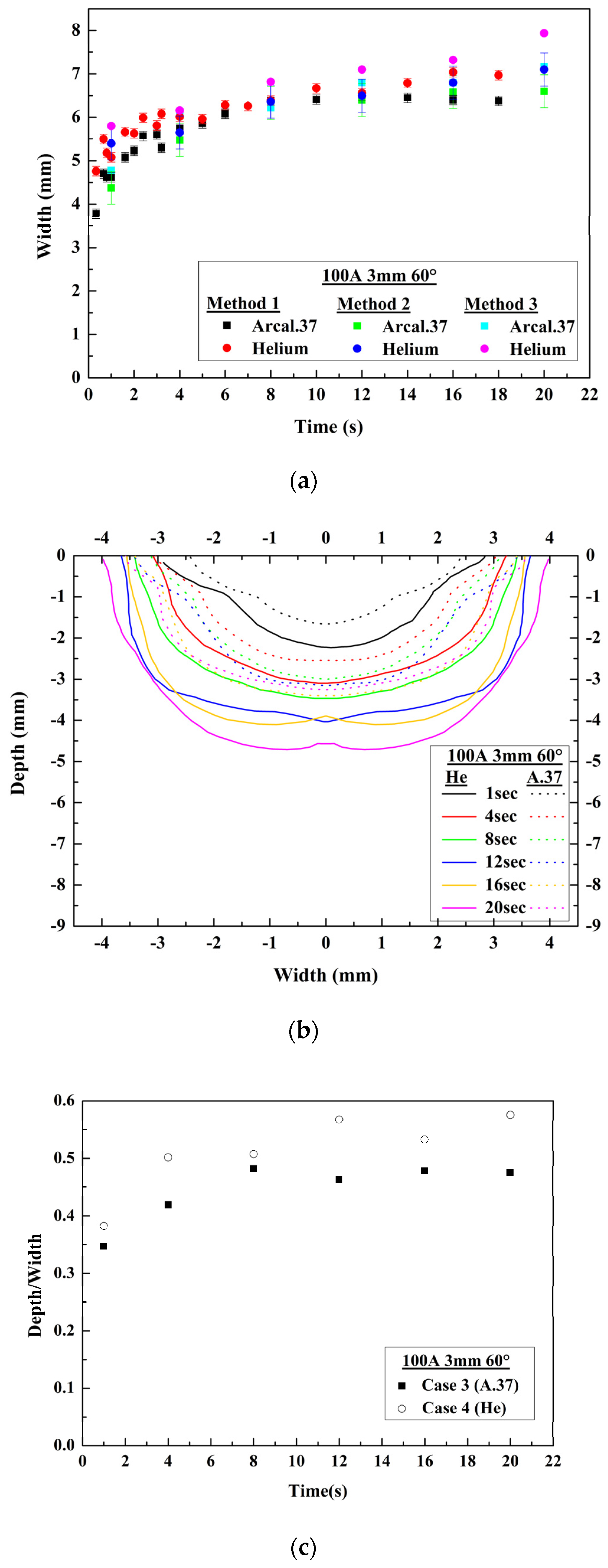
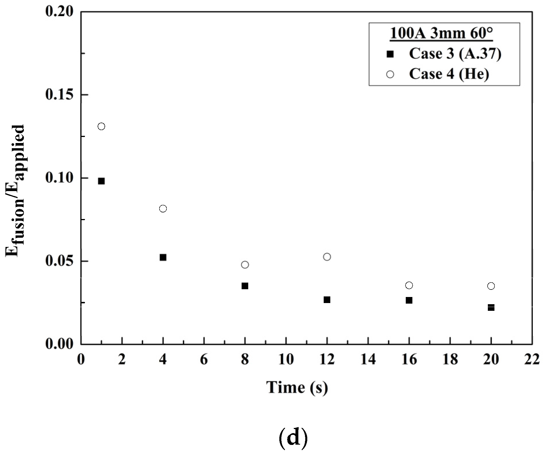
Figure 6.
(a) Effect of the tip angle on the evolution of the weld pool width Arcal.37, 100 A, 5 mm; (b) Effect of the tip angle on the evolution of the weld pool width Arcal.37, 100 A, 3 mm; (c) Effect of the tip angle on the evolution of the weld pool width Helium, 100 A, 3 mm.
Figure 6.
(a) Effect of the tip angle on the evolution of the weld pool width Arcal.37, 100 A, 5 mm; (b) Effect of the tip angle on the evolution of the weld pool width Arcal.37, 100 A, 3 mm; (c) Effect of the tip angle on the evolution of the weld pool width Helium, 100 A, 3 mm.
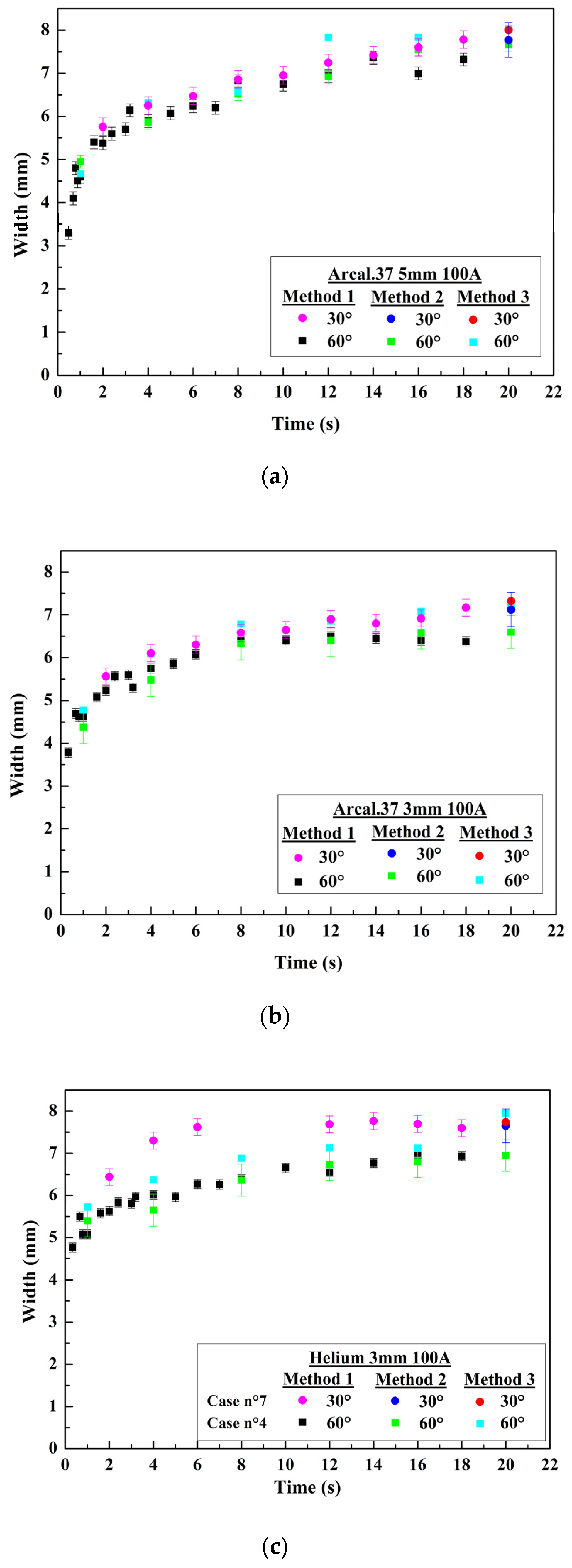
Figure 7.
(a) Effect of the tip angle on the evolution of the weld pool shapes; (b) Effect of the tip angle on the depth-to-width ratio.
Figure 7.
(a) Effect of the tip angle on the evolution of the weld pool shapes; (b) Effect of the tip angle on the depth-to-width ratio.


Table 1.
Details of welding cases.
| Name | Shielding Gas | Welding Current | Arc Length | Tip Angle |
|---|---|---|---|---|
| Case n°1 | Arcal.37 | 100 A | 5 mm | 60° |
| Case n°2 | Arcal.37 | 150 A | 5 mm | 60° |
| Case n°3 | Arcal.37 | 100 A | 3 mm | 60° |
| Case n°4 | Helium | 100 A | 3 mm | 60° |
| Case n°5 | Arcal.37 | 100 A | 5 mm | 30° |
| Case n°6 | Arcal.37 | 100 A | 3 mm | 30° |
| Case n°7 | Helium | 100 A | 3 mm | 30° |
Table 2.
This table indexes width, depth and depth-to-width ratio values using the three methods for the different configurations tested. Width values are estimated with high speed imaging (Method 1) during the interaction and with a picture of the top surface of the electrode at the final instant (Method 2). Metallographic investigations (Method 3) allow evaluating width and depth after the interaction. Uncertainties associated to each method are mentioned between brackets.
| Case n°1: Arcal.37, Current 100 A, Arc length 5 mm, Tip angle 60° | |||||||
| t = 1 s | t = 4 s | t = 8 s | t = 12 s | t = 16 s | t = 20 s | ||
| Width (mm) | Method 1 (±0.15) | 4.60 | 5.89 | 6.83 | 6.94 | 6.99 | 7.66 |
| Method 2 (±0.15) | 4.95 | 5.86 | 6.52 | 6.91 | 7.55 | 7.66 | |
| Method 3 (±0.02) | 4.00 | 6.40 | 6.57 | 7.72 | 7.58 | 8.04 | |
| Depth (mm) | Method 3 (±0.02) | 1.54 | 2.83 | 3.22 | 3.81 | 3.92 | 3.95 |
| Depth-to-Width ratio | 0.39 | 0.44 | 0.49 | 050 | 0.50 | 0.49 | |
| Case n°2: Arcal.37, Current 150 A, Arc length 5 mm, Tip angle 60° | |||||||
| t = 1 s | t = 4 s | t = 8 s | t = 12 s | t = 16 s | t = 20 s | ||
| Width (mm) | Method 1 (±0.15) | 6.38 | 8.55 | 9.45 | 10.20 | 10.25 | 10.77 |
| Method 2 (±0.15) | 5.93 | 8.58 | 9.05 | 9.88 | 10.59 | 10.77 | |
| Method 3 (±0.02) | 6.02 | 8.16 | 9.10 | 10.15 | 10.56 | 10.50 | |
| Depth (mm) | Method 3 (±0.02) | 1.50 | 3.30 | 4.27 | 4.99 | 5.48 | 5.92 |
| Depth-to-Width ratio | 0.25 | 0.40 | 0.46 | 0.49 | 0.52 | 0.56 | |
| Case n°3: Arcal.37, Current 100 A, Arc length 3 mm, Tip angle 60° | |||||||
| t = 1 s | t = 4 s | t = 8 s | t = 12 s | t = 16 s | t = 20 s | ||
| Width (mm) | Method 1 (±0.11) | 4.62 | 5.75 | 6.39 | 6.51 | 6.40 | 6.60 |
| Method 2 (±0.38) | 4.38 | 5.48 | 6.33 | 6.40 | 6.58 | 6.60 | |
| Method 3 (±0.02) | 4.78 | 6.08 | 6.22 | 6.80 | 6.80 | 7.16 | |
| Depth (mm) | Method 3 (±0.02) | 1.66 | 2.55 | 3.00 | 3.15 | 3.25 | 3.25 |
| Depth-to-Width ratio | 0.35 | 0.42 | 0.48 | 0.46 | 0.48 | 0.47 | |
| Case n°4: Helium, Current 100 A, Arc length 3 mm, Tip angle 60° | |||||||
| t = 1 s | t = 4 s | t = 8 s | t = 12 s | t = 16 s | t = 20 s | ||
| Width (mm) | Method 1 (±0.11) | 5.08 | 6.01 | 6.39 | 6.55 | 7.00 | 6.95 |
| Method 2 (±0.38) | 5.40 | 5.65 | 6.36 | 6.73 | 6.80 | 6.95 | |
| Method 3 (±0.02) | 5.80 | 6.16 | 6.82 | 7.10 | 7.32 | 7.94 | |
| Depth (mm) | Method 3 (±0.02) | 2.22 | 3.09 | 3.46 | 4.03 | 3.9 | 4.57 |
| Depth-to-Width ratio | 0.39 | 0.44 | 0.49 | 0.50 | 0.50 | 0.49 | |
| Case n°5: Arcal.37, Current 100 A, Arc length 5 mm, Tip angle 30° | |||||||
| t = 1 s | t = 4 s | t = 8 s | t = 12 s | t = 16 s | t = 20 s | ||
| Width (mm) | Method 1 (±0.20) | - | 6.25 | 6.86 | 7.25 | 7.60 | 7.77 |
| Method 2 (±0.40) | - | - | - | - | - | 7.77 | |
| Method 3 (±0.02) | - | - | - | - | - | 8.00 | |
| Depth (mm) | Method 3 (±0.02) | - | - | - | - | - | 4.25 |
| Depth-to-Width ratio | - | - | - | - | - | 0.53 | |
| Case n°6: Arcal.37, Current 100 A, Arc length 3 mm, Tip angle 30° | |||||||
| t = 1 s | t = 4 s | t = 8 s | t = 12 s | t = 16 s | t = 20 s | ||
| Width (mm) | Method 1 (±0.20) | - | 6.11 | 6.58 | 6.90 | 6.92 | 7.12 |
| Method 2 (±0.40) | - | - | - | - | - | 7.12 | |
| Method 3 (±0.02) | - | - | - | - | - | 7.32 | |
| Depth (mm) | Method 3 (±0.02) | - | - | - | - | - | 3.32 |
| Depth-to-Width ratio | - | - | - | - | - | 0.45 | |
| Case n°7: Helium, Current 100 A, Arc length 3 mm, Tip angle 30° | |||||||
| t = 1 s | t = 4 s | t = 8 s | t = 12 s | t = 16 s | t = 20 s | ||
| Width (mm) | Method 1 (±0.20) | - | 7.30 | 7.57 | 7.69 | 7.70 | 7.65 |
| Method 2 (±0.40) | - | - | - | - | - | 7.65 | |
| Method 3 (±0.02) | - | - | - | - | - | 7.74 | |
| Depth (mm) | Method 3 (±0.02) | - | - | - | - | - | 5.12 |
| Depth-to-Width ratio | - | - | - | - | - | 0.66 | |
Table 3.
The table indexes the applied energy (Eapplied) estimated with measurements of voltage and current intensity during the interaction and the energy (Efusion) involved to fuse the amount of metal related to the weld pool [1].
Table 3.
The table indexes the applied energy (Eapplied) estimated with measurements of voltage and current intensity during the interaction and the energy (Efusion) involved to fuse the amount of metal related to the weld pool [1].
| Arcal.37, Current 100 A, Arc length 5 mm, Tip angle: α | |||||||
| Case n°1: α = 60° | Case n°5: α = 30° | ||||||
| t = 1 s | t = 4 s | t = 8 s | t = 12 s | t = 16 s | t = 20 s | t = 20 s | |
| Efusion (kJ) | 0.097 | 0.361 | 0.462 | 0.752 | 0.690 | 0.854 | 1.365 |
| Eapplied (kJ) | 1.35 | 6.12 | 12.70 | 19.40 | 24.42 | 29.18 | 31.70 |
| γ | 7.18% | 5.89% | 3.63% | 3.87% | 2.82% | 2.92% | 4.30% |
| Arcal.37, Current 150 A, Arc length 5 mm, Tip angle: α | |||||||
| Case n°2: α = 60° | - | ||||||
| t = 1 s | t = 4 s | t = 8 s | t = 12 s | t = 16 s | t = 20 s | - | |
| Efusion (kJ) | 0.150 | 0.630 | 1.270 | 2.070 | 2.905 | 3.030 | - |
| Eapplied (kJ) | 2.40 | 10.01 | 19.40 | 28.73 | 37.02 | 45.70 | - |
| γ | 6.25% | 6.29% | 6.54% | 7.20% | 7.84% | 6.63% | - |
| Arcal.37, Current 100 A, Arc length 3 mm, Tip angle: α | |||||||
| Case n°3: α = 60° | Case n°6: α = 30° | ||||||
| t = 1 s | t = 4 s | t = 8 s | t = 12 s | t = 16 s | t = 20 s | t = 20 s | |
| Efusion (kJ) | 0.111 | 0.297 | 0.362 | 0.427 | 0.577 | 0.614 | 0.850 |
| Eapplied (kJ) | 1.14 | 5.68 | 10.32 | 15.96 | 21.88 | 27.82 | 28.94 |
| γ | 9.73% | 5.22% | 3.50% | 2.67% | 2.63% | 3.44% | 2.93% |
| Helium, Current 100 A, Arc length 3 mm, Tip angle: α | |||||||
| Case n°4: α = 60° | Case n°7: α = 30° | ||||||
| t = 1 s | t = 4 s | t = 8 s | t = 12 s | t = 16 s | t = 20 s | t = 20 s | |
| Efusion (kJ) | 0.187 | 0.478 | 0.652 | 1.029 | 0.972 | 1.230 | 1.145 |
| Eapplied (kJ) | 1.43 | 5.87 | 13.65 | 19.57 | 27.44 | 35.15 | 37.42 |
| γ | 13.00% | 8.14% | 4.77% | 5.26% | 3.54% | 3.50% | 3.06% |
© 2017 by the authors. Licensee MDPI, Basel, Switzerland. This article is an open access article distributed under the terms and conditions of the Creative Commons Attribution (CC BY) license (http://creativecommons.org/licenses/by/4.0/).
Share and Cite
MDPI and ACS Style
Stadler, M.; Freton, P.; Gonzalez, J.-J. Influence of Welding Parameters on the Weld Pool Dimensions and Shape in a TIG Configuration. Appl. Sci. 2017, 7, 373. https://doi.org/10.3390/app7040373
AMA Style
Stadler M, Freton P, Gonzalez J-J. Influence of Welding Parameters on the Weld Pool Dimensions and Shape in a TIG Configuration. Applied Sciences. 2017; 7(4):373. https://doi.org/10.3390/app7040373
Chicago/Turabian StyleStadler, Marine, Pierre Freton, and Jean-Jacques Gonzalez. 2017. "Influence of Welding Parameters on the Weld Pool Dimensions and Shape in a TIG Configuration" Applied Sciences 7, no. 4: 373. https://doi.org/10.3390/app7040373
Note that from the first issue of 2016, this journal uses article numbers instead of page numbers. See further details here.