
Improvement of Interfacial Adhesion of Incorporated Halloysite-Nanotubes in Fiber-Reinforced Epoxy-Based Composites


1
Department of Mechanical Engineering, Korea Maritime and Ocean University, Busan 49112, Korea
2
Department of Material Engineering, Graduate School, Korea Maritime and Ocean University, Busan 49112, Korea
*
Author to whom correspondence should be addressed.
Appl. Sci. 2017, 7(5), 441; https://doi.org/10.3390/app7050441
Submission received: 20 February 2017
/
Revised: 10 April 2017
/
Accepted: 22 April 2017
/
Published: 27 April 2017
(This article belongs to the Special Issue Surface Modification of Halloysite Nanotubes)
Abstract
:The heart of composite materials depends on the characteristics of their interface. The physical properties of composite materials are often described by the rule of mixtures, representing the average physical properties of the reinforcement and the matrix resin. However, in practical applications there are situations which arise where the rule of mixtures is not followed. This is because when an external energy applied to the composite material is transferred from the matrix to the reinforcement, the final physical properties are affected by the interface between them rather than the intrinsic properties of both the reinforcement and the matrix. The internal bonding strength of the interface of these composites can be enhanced by enhancing the bonding strength by adding a small amount of material at the interface. In this study, the mechanical properties were evaluated by producing a carbon fiber-reinforced composite material and improved by dispersing halloysite nanotubes (HNTs) and the epoxy resin using an ultrasonic homogenizer. The interfacial bond strength increased with the addition of HNT. On the other hand, the addition of HNTs more than 3 wt % did not show the reinforcing effect by HNT agglomeration.
1. Introduction
The interface of composite materials is the heart of composite materials. There is a significant difference between the physical and chemical properties or the mechanical properties of the reinforcing fibers and the matrix resin itself [1]. Therefore when the materials are combined, the nature of the interface between the dissimilar materials can have a profound impact on the mechanical properties of the composite material. The physical properties of composite materials are often described by the rule of mixtures, which represent the average physical properties of the reinforcement and the matrix resin. However, in practical applications, situations arise when the rule of mixtures is not followed. This is because when an external energy is applied to the composite material, it is transferred from the matrix to the reinforcement, affecting the final physical properties of the interface between them rather than the intrinsic properties of both the reinforcement and the matrix. In addition, each matrix or reinforcement forms strong internal chemical bonds, and their interface forms weak physical bonds. Because of this, a force delivered from outside is dependent on the extent of the physical bonding [2,3].
In general, composite materials, which do not have any surface treatment of carbon fibers, are known to show a low degree of interlaminar shear strength (ILSS) or critical stress intensity factor (KIC). This is due to the fact that carbon fiber, which is used as reinforcement, has a low wettability level with the matrix and the surface itself is smooth, and thus the interfacial bonding strength is weak [4]. Therefore, the interfacial bonding strength of carbon fiber-reinforced composite material can be improved by two methods. (i) first removing impurities on the surface of the carbon fiber with surface treatment methods such as vapor phase oxidation, liquid phase oxidation, anodic oxidation, and plasma treatment. After that the number of functional groups (carboxyl, carbonyl, and hydroxyl) enhancing the bonding force with the matrix, is increased [5]; (ii) the interfacial bonding strength can be improved be adding trace amounts of other materials such as SiC [6] and TiO2 [1] between the carbon fibers and the matrix.
In this research, carbon fiber-reinforced composite materials were produced by dispersing HNTs and expected to enhance the interfacial bonding strength between the carbon fibers and the matrix, and epoxy resin using an ultrasonic homogenizer. In order to analyze the mechanical behavior in the presence of added HNTs to carbon fibers and the matrix, first the mechanical behavior of the HNT/matrix-based composites was observed by dispersing HNTs in the matrix. Based on this, the mechanical properties were evaluated in accordance with the interfacial bonding strength according to the addition of particles with varying HNT content.
Also, mode II interlaminar fracture toughness was measured and evaluated to investigate the fracture phenomenon at the interface of carbon fiber reinforced composite with nanoparticles. In order to investigate the interfacial reinforcement effect of HNTs, nanoparticles were dispersed only in epoxy resins, and mechanical properties were evaluated to compare the reinforcing effect in the resin and the theoretical and experimental properties of the layered composite material.
2. Experimental
2.1. HNT Particle Dispersion
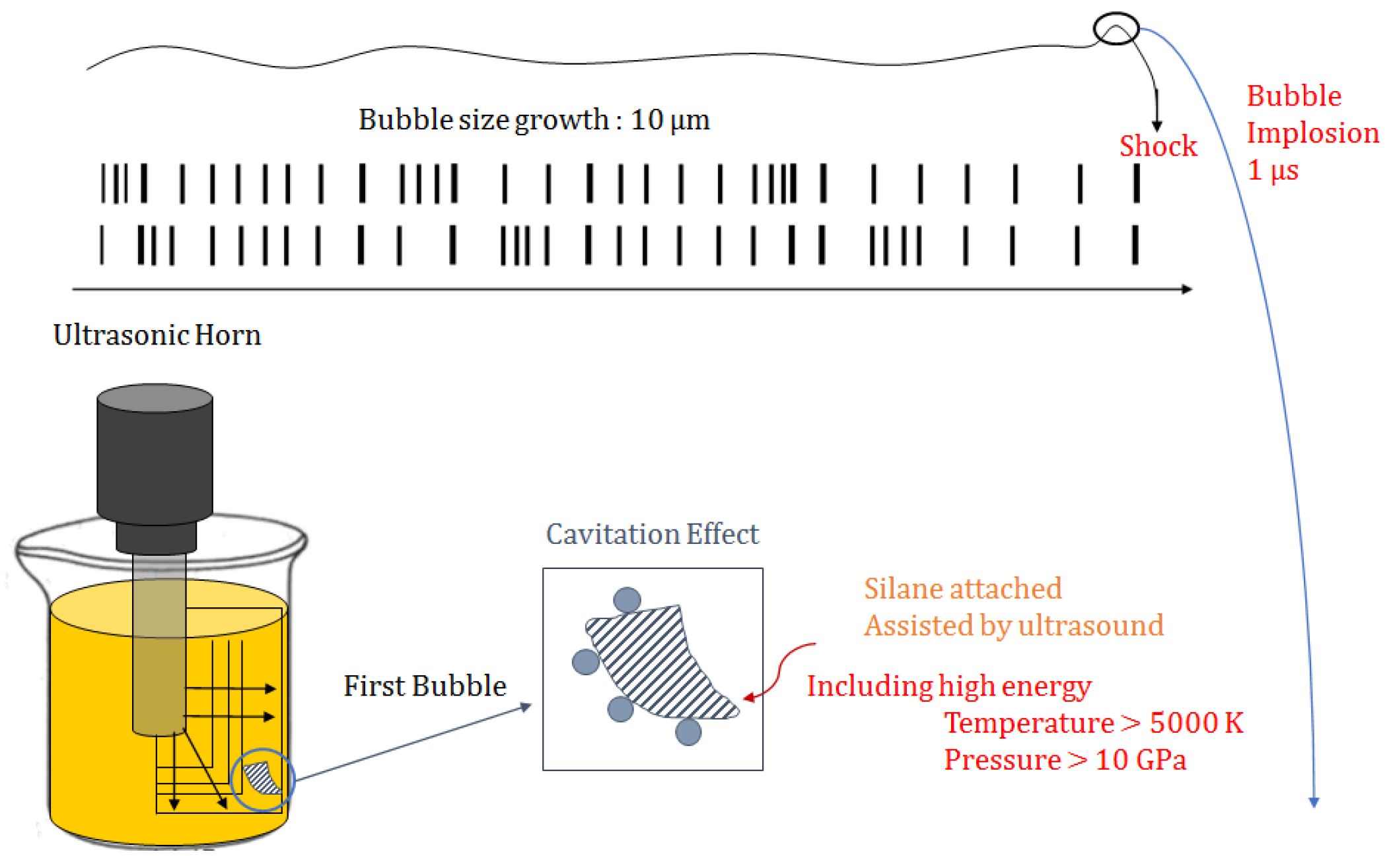
In order to prevent the agglomeration of the epoxy resin and the HNT (DOORICHEM, Seoul, Korea) nanoparticles, the additives were dispersed using an ultrasonic dispersion device. The cavitation effect as shown in Figure 1 is generated by high-intensity ultrasound. When ultrasonic waves are introduced into the solution, a wave forms and propagates through the liquid. At this point, positive pressure is generated in the direction the wave is moving, instantly leaving the negative pressure behind. This difference in pressure creates waves, and as these get larger, millions of microcavities of microscopic vacuum bubbles are generated. The bubbles easily form in hollows or cavities and implode violently due to the change in the pressure of the ultrasonic waves. At this point a strong shock wave forms caused by strong liquid jets and swirls. The collapse of the microcavities occurs in microseconds (µs), taking place many million times in a very small area. Pressures of more than 10 GPa and temperatures of 5000 K are reached [4,7]. The force generated at this time is powerful enough to corrode the propeller of a ship or generate noise. By applying the cavitation effect to the composite material, the penetration of the polymer resin into the carbon fiber was facilitated.
2.2. Production of Test Specimens and Interfacial Properties Evaluation
In this study, HNTs were used as the additive for a carbon fiber-reinforced composite for reinforcing effect. Two types of test specimen were produced with HNT/matrix and HNT/carbon fiber/matrix material. SK-N300 fiber was used in this study as the carbon fiber and supplied by SK Chemicals, Korea; its basic physical properties are listed in Table 1a.
Among the widely used matrix in the industry, an epoxy resin with superior physical properties was selected as the matrix. To disperse the nanoparticles, KFR-120 epoxy resin with low viscosity from Kukdo Chemical Co., Ltd. (Seoul, Korea) was used. KFH-160 was used as a hardener at a 100:30 weight ratio. The basic physical properties of the epoxy and hardener are listed in Table 1b.
The tensile strength of HNT was measured at 0, 0.5, 1, 2, 3, 5, 8, and 10 wt % to take into account the cohesion of HNT and understand the range of cohesion of HNT in a matrix with viscosity and its phenomenon. The test specimens with HNT added to the carbon fiber composite material were prepared by dispersing nanoparticles in an epoxy resin using an ultrasonic dispersing machine and then preparing prepregs directly. The prepared prepreg resin was subjected to vacuum bagging to prepare a test piece. To evaluate the results, the tensile test and interlaminar shear test were performed according to ASTM D5766-2002 strandard test method for open-hole tensile strength of polymer matrix composite laminates and ASTM D2344 standard test method for short-beam strength of polymer matrix composite materials and their laminates. The DCB test specimens were prepared by laminating six sheets of prepregs with nanoparticles added and adding a Teflon sheet to the middle of the prepregs to form a first crack. The DCB test specimens were tested according to ASTM D 6671 standard test method for mixed mode I-mode II interlaminar fracture toughness of unidirectional fiber reinforced polymer matrix composites. In all tests, 10 test specimens were produced and the average of 8 test specimens excluding the maximum and minimum values was obtained.
3. Results and Discussion
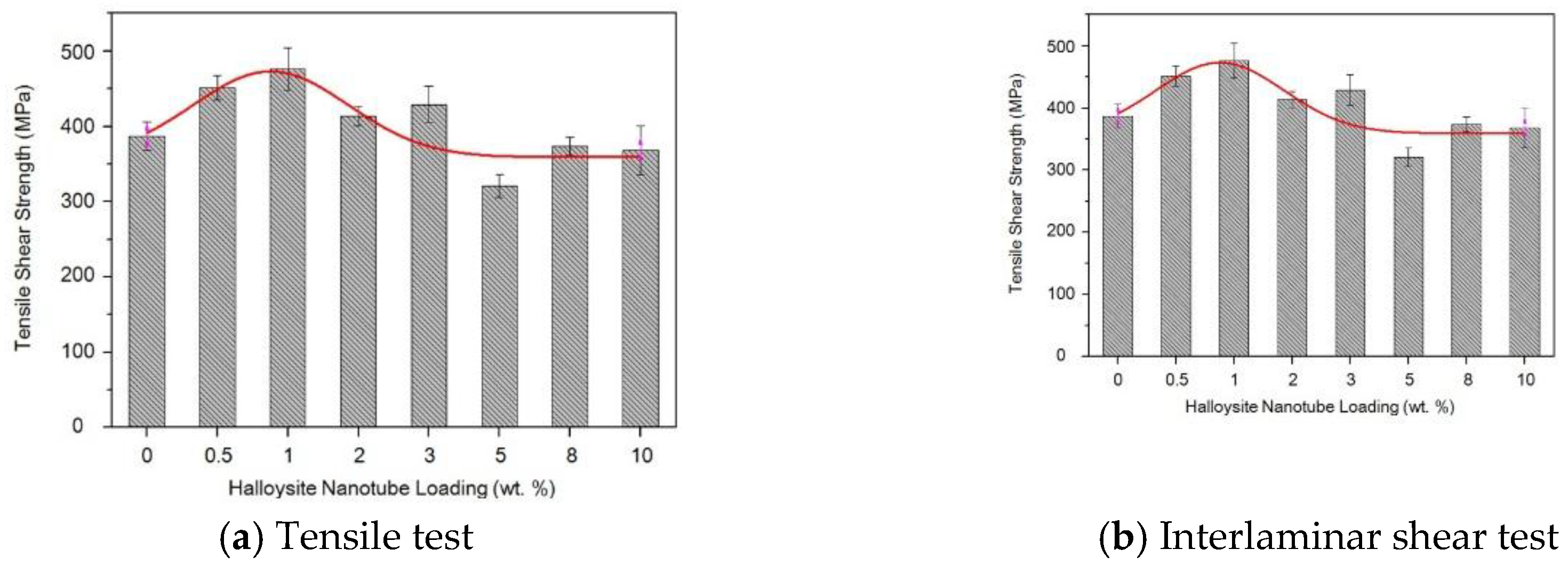
Tensile strength was investigated to evaluate the effect of HNTs on the tensile strength of carbon fiber-reinforced composite material. The respective mean value of the eight sets was calculated excluding the minimum and maximum values. These results are shown in Figure 2a. The tensile strength of the test specimens increased in accordance with the added amount of HNT content up until 1 wt %. However, the tensile strength tended to decrease after 1 wt % HNT content. In particular, the specimen with an HNT content of >5 wt % had a smaller tensile strength than the specimens with no added HNT. In the case where the content of the HNT increased beyond a certain level, it is believed that by increasing the cohesion of the HNT, the tensile strength decreased according to the stress concentration in the agglomerated HNT.
The interlaminar shear test was carried out to evaluate the interfacial properties of carbon fiber/epoxy composite with added HNTs. The ILSS with varying amount of HNTs is shown in Figure 2b. The ILSS of carbon fiber-reinforced epoxy composite without any added HNT was ~26.29 MPa, which was even lower than the test specimen with 10 wt % HNT showing the smallest strengthening effect with the addition of HNTs. The ILSS improved by adding HNTs. In addition, when the added HNT content was up to 3 wt %, the ILSS increased with added amount, and starting at 3 wt %, as the content was increased, the ILSS decreased. When more than a certain amount of HNTs was added, the effect of the addition was found to be small. In the case where a comparatively high amount was added to the epoxy resin, even when dispersed, the HNTs clumped together and were not uniformly dispersed by visual observation. It was surmised that stress concentration due to such agglomeration decreased the strength.
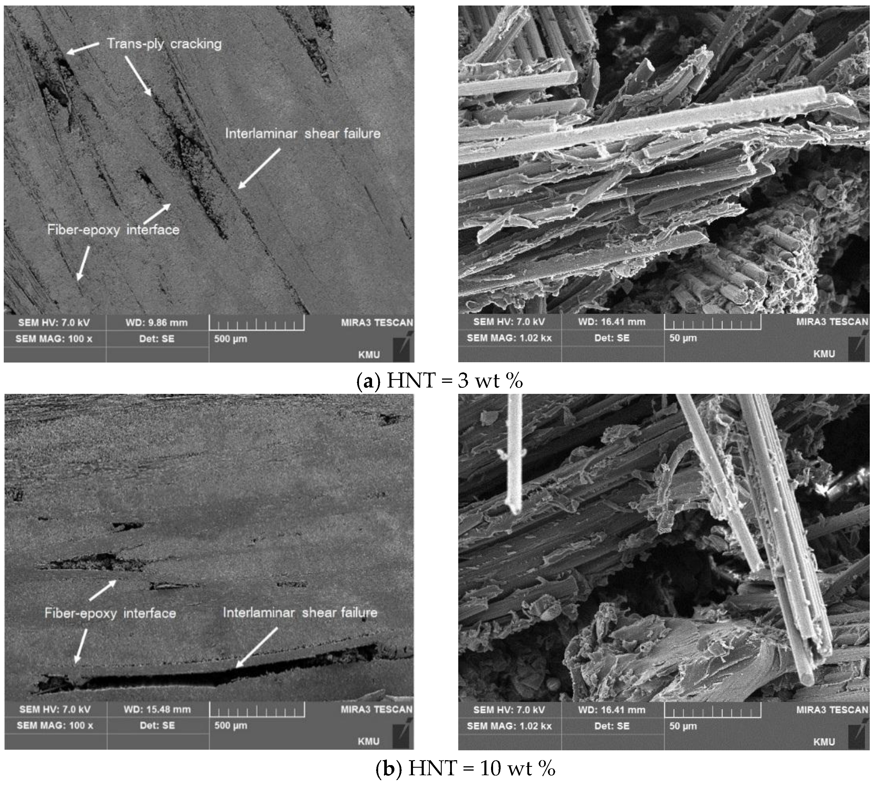
The left side in Figure 3 shows the SEM image of a test specimen with a fracture cut from the front side after the interlaminar shear test of the carbon fiber-reinforced composite with added HNTs. A test specimen with an HNT content of 10 wt %, compared to the test specimen with 3 wt % HNT content, had the maximum shear strength value, forming a significant interlaminar shear fracture, and the damaged side of the fractured surface was seen to be smooth.
An image of the fractured surface, which was taken to evaluate the fracture’s shape is shown in the right side of Figure 3. With an HNT content of 3 wt %, the pull-out phenomenon was relatively small in the entire fractured surface, and the epoxy resin was also observed to be adhering well to the surface of the carbon fiber. In addition, at an HNT content of 10 wt %, the pull-out phenomenon such as the white part in the SEM image of the test specimen appeared in every aspect of the fiber, and in particular, delamination appeared near or at the fiber-resin interface. It is believed that the reason delamination appears locally is because of the stress concentration from the agglomeration of the HNTs. In order to prevent the agglomeration of the epoxy resin and the HNT nanoparticles, it was dispersed using an ultrasonic dispersion device. An ultrasonic dispersion device was used to incorporate the cavitation effect into the composite material.
Figure 4 shows the graph of mode II shear modulus with varying HNT content to evaluate mode II interlaminar fracture toughness of carbon fiber reinforced composite with HNT. The interfacial bond energy increased up to 3 wt % of HNT, but decreased at ≥5 wt % HNT content. The binding energy of HNT increased for 3 wt % at the interface, but at ≥5 wt %, the binding energy of HNT was concentrated due to the concentration of HNT. To evaluate the interfacial bond energy of HNT—reinforced carbon fiber reinforced composites and the strengthening effect of HNT addition, HNT was added to the epoxy resin to evaluate the strengthening effect of epoxy resin by HNT. Figure 5 shows the result of the tensile strength by adding HNT to the epoxy resin. The strength of the epoxy resin without HNT was 22 MPa, and the addition of HNT strengthened the effect by two to three times, confirming remarkable epoxy resin strengthening effect by the addition of HNT, and the increase in the tensile strength by addition increased the content of HNT to 5 wt %. In ≥5 wt % of test specimens, the strengthening effect gradually decreased with addition.
In order to investigate the correlation between the strengthening effect of HNT in epoxy resin and the mechanical properties of carbon fiber reinforced composite material by the addition of HNT by the improvement of interfacial bonding energy based on the results obtained above, the strength characteristic value of the epoxy resin reinforced with HNT, and the strength characteristics of carbon fiber were obtained by the theoretical strength of the composite material.
The displacement and the strain of the composite laminate under load are different from those of the single layer composites, because of the interaction between the layers. In the composite laminate, the lamination angles are different for each layer, so the stiffness and strength are different for the same external force. The force and moment applied to the laminate can be obtained by integrating different forces and moments for each layer depending on the laminate thickness. Assuming the planar stress state of the laminates, the forces and moments applied to the laminates are as follows.
where Nij is the applied force per unit length of the laminate and Mij is the applied force per unit length of the laminate. Figure 6 is the moment applied per unit length of the laminates.
Here, the average stress of the composite material is given by the following equation, and t is the total thickness of the composite laminate.
To compare the strength of the theoretically strengthened composite with the actual strength, the fiber volume fraction was calculated to investigate the strength of the theoretical composite material. The fiber contents of composite specimens were tested in accordance with ASTM D 3171, and determined using the following formula.
where m1, m2, m3 are the initial mass (g) of the dried container only, the mass of the container (g) containing the dried test specimen, and the mass of fiber (g), respectively. The volume content of the fibers measured by each method was ~62%, and the weight of the added HNT was calculated by assuming that the HNT was dispersed in the epoxy resin.
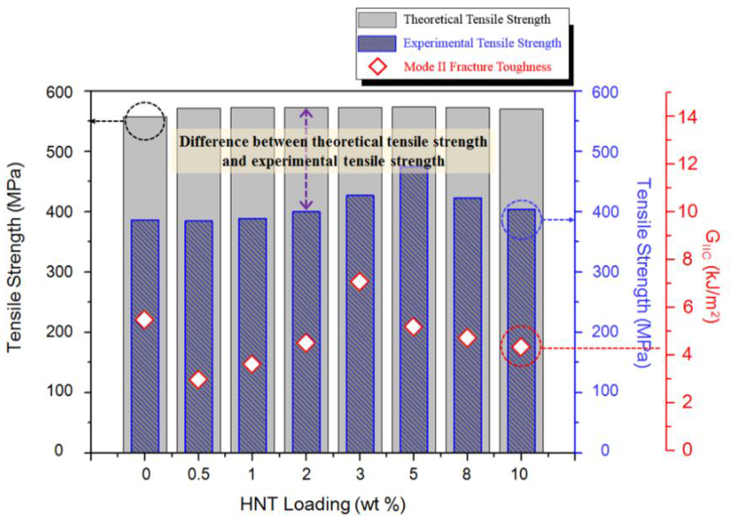
Figure 7 shows the graph comparing the theoretical strength obtained by calculation with the carbon fiber reinforced composite material and interlaminar fracture toughness energy added with HNT. The theoretically calculated values were ~20 MPa higher than the test specimens without HNT. The difference in the strengthening effect due to the additive content was insufficient in the theoretical calculation. Theoretically, the calculation of the strength of a composite material does not seem to have any effect on the theoretically calculated value because it is dominated by fiber, which is a reinforcing material, rather than a known resin. However, the measured value of HNT was the highest at 5 wt % HNT, because the binding force at the interface increased with increasing amount of added HNT. Moreover, it is considered that the addition of HNT which is not calculated theoretically is due to the interfacial adhesion strengthening effect.
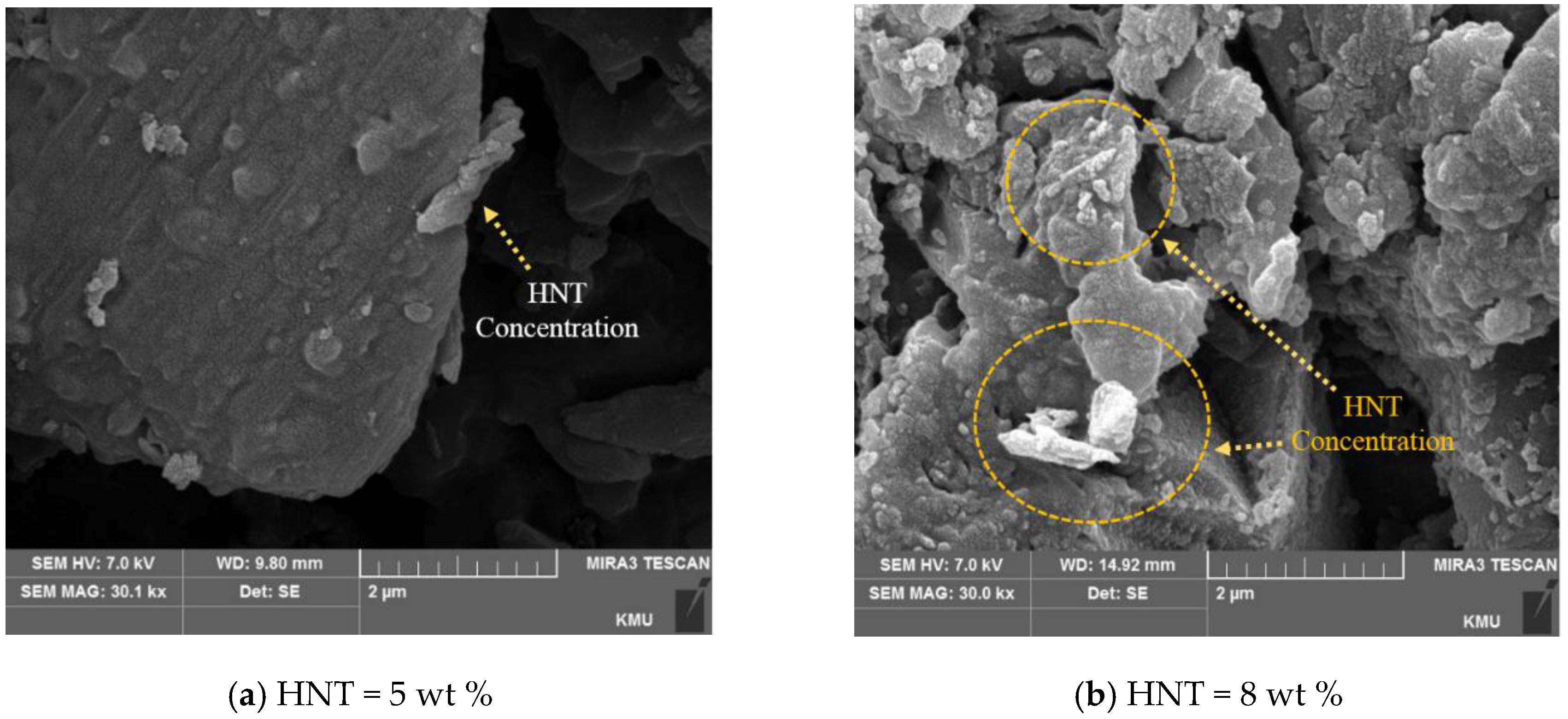
The cohesion of the HNT in the carbon fiber reinforced composite material was investigated by SEM. Figure 8 shows the photograph of specimens taken at 5 wt % HNT having the highest tensile strength value, and at 8 wt %, the tensile strength decreases with increasing content. The photograph of the sample with 8 wt % HNT shows a considerable amount of agglomerated HNTs.
4. Conclusions
In this study, the interfacial bonding strength between carbon fibers and epoxy resins of the composite test specimens with added HNTs was measured. The added HNT was expected to enhance the interfacial bonding strength between carbon fibers and epoxy resins. The conclusions of this study are as follows.
- (1)
- The addition of HNT reinforced the tensile strength of the composite material, and the tensile strength had a greater effect on the bonding force between the fiber and the resin than the effect on the resin.
- (2)
- Where the added amount of HNTs was up to 3 wt %, the tensile strength of the carbon fiber-reinforced composite material increased, but for higher content than that, strength decreased. In the case of the addition of higher content, this is considered to be due to the cohesive strength of HNTs decreasing the stress concentration.
- (3)
- The addition of HNTs showed a steady increase in the strength until the addition of 3 wt % of nanoparticles, but after that the ILSS decreased with increasing HNT content. This is probably because of the inherent nature of HNTs, where an increase in content leads to agglomeration of the HNTs, decreasing the strength values due to local stress concentration.
- (4)
- The size of GIIC due to the addition of HNT increased up to 3 wt %, but decreased thereafter. With increasing HNT content, the aggregated part due to the dispersion of HNT is locally acting as a stress concentration, decreasing the fracture energy.
- (5)
- According to the GIIC size based on the interlaminar fracture toughness evaluation of HNT, the nanoparticles with very low cohesive strength are thought to have the highest interlayer energy at ~3 wt %, and the content of nanoparticles depends on the cohesive force. The strengthening effect was insignificant according to the addition amount because of the reduction in the fracture energy.
Acknowledgments
This research was supported by the Ministry of Trade, Industry & Energy (MOTIE), Korea Institute for Advancement of Technology (KIAT) through the IDEA FACTORY Research Grant of N0001410.
Author Contributions
Jin-Woo Lee and Yun-Hae Kim conceived and designed the experiments; Jin-Woo Lee and Soo-Jeong Park performed the experiments; Jin-Woo Lee analyzed the data; Yun-Hae Kim contributed reagents/materials/analysis tools; Jin-Woo Lee, Yun-Hae Kim and Soo-Jeong Park wrote the paper.
Conflicts of Interest
The authors declare no conflict of interest.
References
- Moon, Y.J.; Choi, J.Y.; Kim, B.A.; Moon, C.K. Effect of TiO2 Nanoparticle on the Mechanical and Thermal Properties of Epoxy Resin Composites. J. Korea Soc. Power Syst. Eng. 2010, 14, 68–75. [Google Scholar]
- Park, S.J.; Kim, T.J.; Lee, J.R.; Hong, S.K.; Kim, Y.K. Influence of Sizing Agent on Interfacial Adhesion and Mechanical Properties of Glass Fiber/Unsaturated Polyester Composites. Polymer (Korea) 2000, 24, 326–332. [Google Scholar]
- Choi, Y.M. Study of Nanoparticle Effect on Durability of Carbon Fiber/Epoxy Composites in Moisture Environment. Master’s Thesis, Pukyong National University, Busan, Korea, 2014. [Google Scholar]
- Oh, D.Y. Physical and Chemical Treatment to Improve Interfacial Adhesion Strength of Carbon Fiber Reinforced with Hybrid Composites. Master’s Thesis, Pusan National University, Busan, Korea, 2012. [Google Scholar]
- Hong, M.S.; Bae, K.M.; Choi, W.K.; Lee, H.S.; Park, S.J.; An, K.H.; Kim, B.J. A Study on Mechanical Interfacial Properties of Copper-plated Carbon Fibers/Epoxy Resin Composites. Appl. Chem. Eng. 2012, 23, 313–319. [Google Scholar]
- Kwon, D.J.; Wang, Z.J.; Kim, J.J.; Jang, K.W.; Park, J.M. Improvement of Mechanical and Interfacial Properties of Carbon Fiber/Epoxy Composites by Adding Nano SiC Fillers. J. Adhes. Interface 2013, 14, 75–81. [Google Scholar] [CrossRef]
- Kim, Y.B. Surface Modification of Nanoparticles for Enhancing Dispersion and Application to Nanocomposites. Master’s Thesis, Sejong University, Seoul, Korea, 2011. [Google Scholar]
Figure 1.
The ultrasonic dispersion of nanoparticles in the base material using the cavitation behavior.
Figure 1.
The ultrasonic dispersion of nanoparticles in the base material using the cavitation behavior.

Figure 2.
Comparison of tensile strength (a) and interlaminar shear strength (b) of carbon fiber-reinforced composites according to HNT content.
Figure 2.
Comparison of tensile strength (a) and interlaminar shear strength (b) of carbon fiber-reinforced composites according to HNT content.

Figure 3.
Internal image of the damaged zone (left) and a fracture (right) of HNT carbon fiber-reinforced composites taken using SEM equipment.
Figure 3.
Internal image of the damaged zone (left) and a fracture (right) of HNT carbon fiber-reinforced composites taken using SEM equipment.

Figure 4.
Mode II shear modulus of CFRP according to HNT addition.
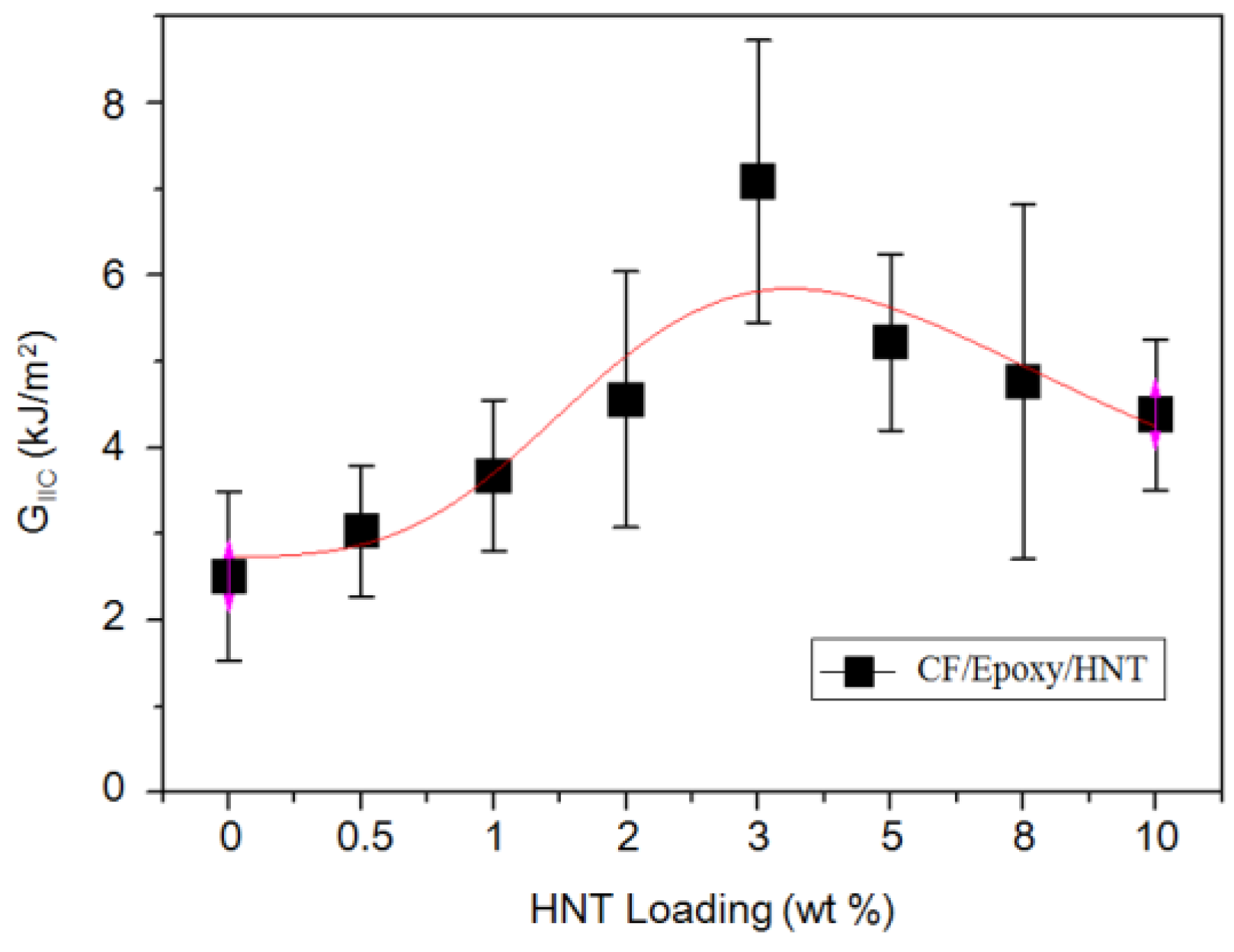
Figure 5.
Comparison of tensile strength of HNT added epoxy with HNT content.
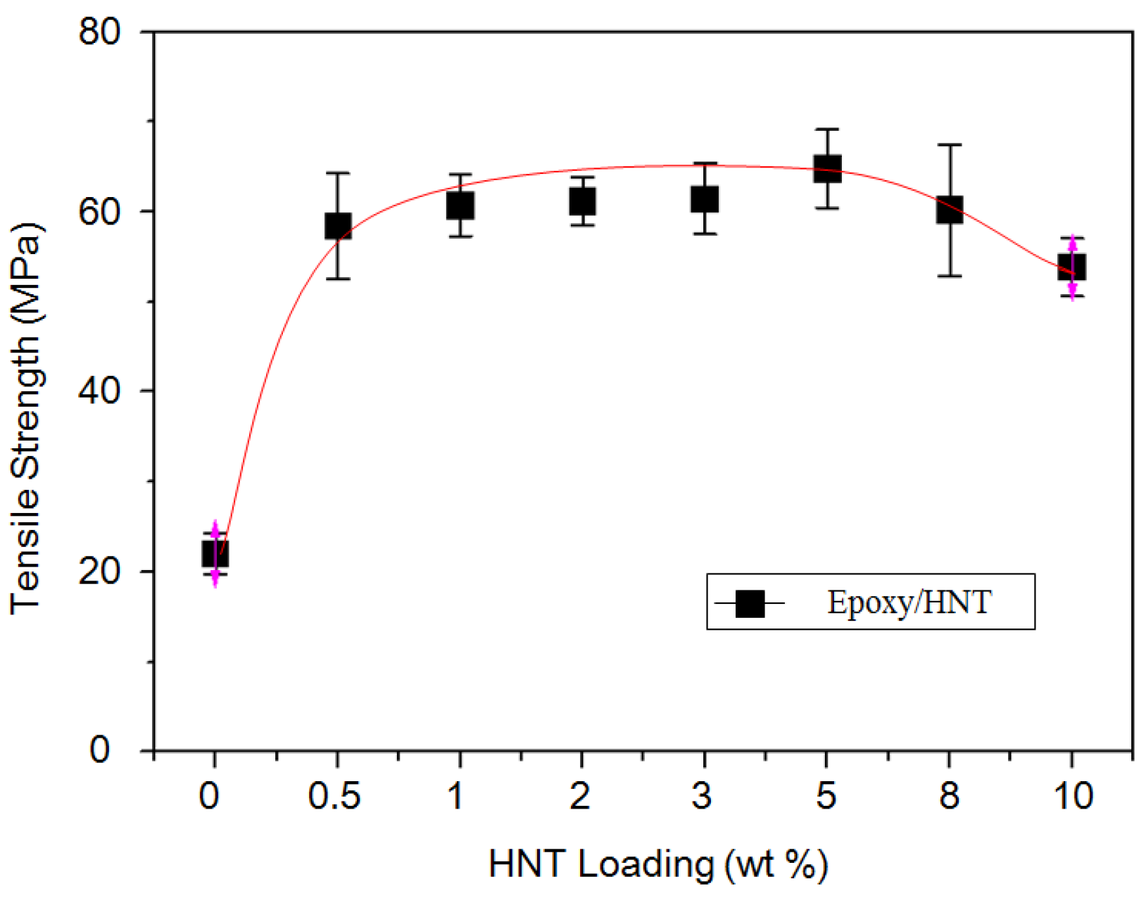
Figure 6.
Positive resultant forces and moment.
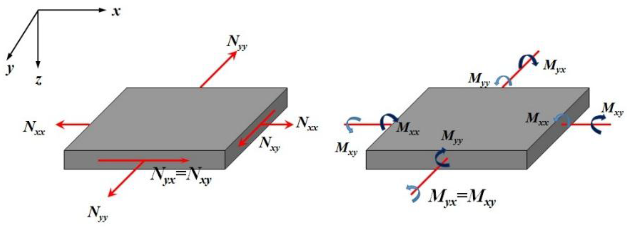
Figure 7.
A graph of the relationship between the theoretical tensile strength, the experimental tensile strength, and the interlaminar fracture toughness of CFRP according to the HNT content.
Figure 7.
A graph of the relationship between the theoretical tensile strength, the experimental tensile strength, and the interlaminar fracture toughness of CFRP according to the HNT content.

Figure 8.
Scanning electron micrographs of EP/CF/HNT composites.

Table 1.
Mechanical properties of main materials used in this study.
| (a) Carbon Fiber Used as the Reinforcement | |||||
| Properties | Tensile Strength | Density | Elastic Modulus | Diameter | |
| Value | |||||
| Carbon fiber | 4694 MPa | 300 g/m2 | 26.2 GPa | 11–15 µm | |
| (b) Epoxy Resin Used as the Matrix | |||||
| Properties | Equivalent Weight (g/eq, EEW) DIN EN ISO 3001 | Density (g/mL) DIN EN ISO 1675 | Viscosity (cps) DIN EN ISO 2555 | Total Amine Value (mgK OH/g) | |
| Value | |||||
| KFR-120 | 170–180 | 1.0–1.2 | 1000–1500 | - | |
| KFH-160 | - | 0.8–1.0 | 5–50 | 400–600 | |
© 2017 by the authors. Licensee MDPI, Basel, Switzerland. This article is an open access article distributed under the terms and conditions of the Creative Commons Attribution (CC BY) license (http://creativecommons.org/licenses/by/4.0/).
Share and Cite
MDPI and ACS Style
Lee, J.-W.; Park, S.-J.; Kim, Y.-H. Improvement of Interfacial Adhesion of Incorporated Halloysite-Nanotubes in Fiber-Reinforced Epoxy-Based Composites. Appl. Sci. 2017, 7, 441. https://doi.org/10.3390/app7050441
AMA Style
Lee J-W, Park S-J, Kim Y-H. Improvement of Interfacial Adhesion of Incorporated Halloysite-Nanotubes in Fiber-Reinforced Epoxy-Based Composites. Applied Sciences. 2017; 7(5):441. https://doi.org/10.3390/app7050441
Chicago/Turabian StyleLee, Jin-Woo, Soo-Jeong Park, and Yun-Hae Kim. 2017. "Improvement of Interfacial Adhesion of Incorporated Halloysite-Nanotubes in Fiber-Reinforced Epoxy-Based Composites" Applied Sciences 7, no. 5: 441. https://doi.org/10.3390/app7050441
Note that from the first issue of 2016, this journal uses article numbers instead of page numbers. See further details here.