
Experimental Study on Heat Transfer Performance of Vacuum Tube Heat Collector with Thermal Storage

1
School of Energy and Environment, Southeast University, Nanjing 210096, China
2
Jiangsu Provincial Key Laboratory of Solar Energy Technology, Nanjing 210096, China
*
Author to whom correspondence should be addressed.
Appl. Sci. 2017, 7(5), 448; https://doi.org/10.3390/app7050448
Submission received: 11 March 2017
/
Revised: 25 April 2017
/
Accepted: 25 April 2017
/
Published: 28 April 2017
(This article belongs to the Special Issue Advances in Thermal System Analysis and Optimization)
Abstract
:This experimental study is intended to explore the heat performance of a novel vacuum tube heat collector with thermal storage. In order to enhance the heat transfer performance, we add radial metal fins to the U-tube which is used as the heat transfer channel of water. Meanwhile, in order to increase the thermal capacity of the heat collector, the heat collector model is designed to be larger than the general collector and is filled with the phase change materials (PCMs). In the U-tube, paraffin is chosen as the PCM. Then, during the experiment, to study the energy absorption and desorption characteristics of the heat collector, we chose to test during the day and night in the summer and the transition season. The experimental results show that, at night, the outlet water temperature of the vacuum tube heat collector has been enhanced by using PCM. The outlet water temperature decreases with the increase of flow rate.
1. Introduction
The vacuum tube collector is effective in low temperature solar energy applications. However, due to natural conditions such as weather and other random factors, the available solar energy is extremely unstable. In order to overcome the disadvantages as noted above, it is necessary to put forward a suitable solution regarding the energy storage conditions such that the radiant energy from the sun is able to be utilized in the evening or on rainy days. When considering the filling material used to elevate the heat storage capacity, the author has chosen paraffin as the phase change material (PCM) which possesses many advantages. For example, paraffin excludes the super cooling phenomenon; chemical reactions and corrosion are less likely to occur in paraffin; the price of paraffin is low and so on. However, paraffin has a significant disadvantage—its thermal conductivity is low. Therefore, great attention has been paid to the search for an effective method to enhance the heat transfer of paraffin.
In recent years, various methods have been proposed to enhance the heat transfer in the latent heat thermal store system. Due to the development of nanotechnology, many researchers have tried to prepare high-performance composite PCMs by adding nanoparticles. Khodadadi et al. [1] analyzed the high heat release rate of nanoparticle-enhanced PCMs by the CFD method. Elgafy et al. [2] studied the thermal conductivity of the mixture of pure paraffin wax and carbon nanofibers. The utilization of heat pipe and thermosiphons has also been given attention. Saeed Tiari et al. [3] studied the effects of heat pipe spacing, fin length and numbers and the influence of natural convection on the thermal response of the thermal energy storage unit. Nourouddin Sharifi et al. [4] used a novel heat pipe-metal foil approach to enhance the heat transfer progress of a PCM (99% pure n-octadecane with a melting temperature of 28 °C). Besides, the application of finned tubes with different configurations has been studied by various researchers [5,6,7,8,9,10]. Eftekhar et al. [5] have studied the heat transfer effect of adding metal fins in the energy storage system filled with paraffin. They placed the heat storage equipment with fins between two surfaces with constant temperature to form the heat transfer model. By measuring and photoing the temperature of the melting zone, they found that the presence of fins could provide additional heat conduction paths and enhance the natural convection effect in the melting transition zone. Padmanabhan et al. [10] analyzed how the circular annulus enhanced the heat transfer in the heat storage system. They did parameter analysis on two cases in one of which the entire casting ring was arranged with rectangular fins and in the other the inner surface of the circular was arranged with round fins. From their experiment, they obtained the formula for calculating the volume fraction of the PCM at any time.
Other heat transfer enhancement techniques have been reported [11,12,13,14,15]. For instance, foam metals are attracting growing attention. Zhang Peng et al. [11] studied the heat transfer characteristics of a composite phase change material composed of paraffin and metal foam. In their study, the composite PCM was fabricated by using copper foam to enhance the thermal conductivity of paraffin. Jialin Yang et al. [12] designed an experiment to investigate the dynamic thermal behavior of a shell-and-tube latent heat thermal storage unit. Their experimental results indicated that the influence of heat transfer fluid (HTF) temperature on the charging process is more significant than that of the HTF flow rate. Zhang Peng et al. [13,14] also studied the charging and discharging process of a shell-tube latent heat storage system. They found that the performance of the latent thermal energy storage system was affected notably by the types of PCMs, HTF temperatures and flow rates. Rajesh Baby and C. Balaji [15] investigated the effect of metal foams and PCM on the heat transfer performance of a heat sink.
In the field of solar energy storage, K. S. Reddy [16] built and analyzed a thermal model of the solar integrated collector storage water heating system with PCM. M.H. Mahfuz et al. [17] performed energy and exergy analyses for the thermal energy storage system with PCM. They concluded that the total life cycle cost decreases with the increase of flow rate. A. Reyes et al. [8] designed a new type of solar energy collector using soft drink cans filled with paraffin wax. This low-cost accumulator can be applied in drying processes or a household calefaction system. G. Murali and K. Mayilsamy studied the performance of a solar water heater system using latent thermal energy storage under discharging mode [18]. A. Sakhrieh et al. [19] studied the effect of using a PCM on the storage capacity of a conventional solar storage system under Jordanian Climate. A. El Khadraoui et al. [20] carried out a comparative experiment to evaluate the performance of the solar air collector with and without PCM. Their results showed that the PCM cavity increased the outlet air temperature of a Solar Air Heater with PCM by differences between 3 °C and 7 °C compared to the Solar Air Heater without PCM during the night.
In summary, much research has focused on the heat transfer characteristics of latent heat storage systems. However, few researchers are concerned about the development of new thermal storage solar collectors; in particular, little research focuses on the energy storage vacuum tube solar collectors. Thus, in this paper, a new type of vacuum tube collector with metal fins filled with paraffin is designed and evaluated experimentally. Also, the charging and discharging processes are carried out under different climatic conditions to further understand the heat transfer characteristics of the novel design.
2. The Construction of the Experimental Platform
2.1. Development of Energy Storage Vacuum Tube Collector
The U-type copper tubes with 10 mm internal diameter and 12 mm external diameter are used here as the main heat exchanger components. The cylindrical aluminum fins are uniformly distributed around the tubes radially. The fin thickness is 4 mm and the space between fins is 40 mm. The U-type tube and aluminum fins are connected by welding. The pressure leak detection is done by imposing 1 MPa oxygen on the U tube. The processing diagram of U copper tube and fin is shown in Figure 1.
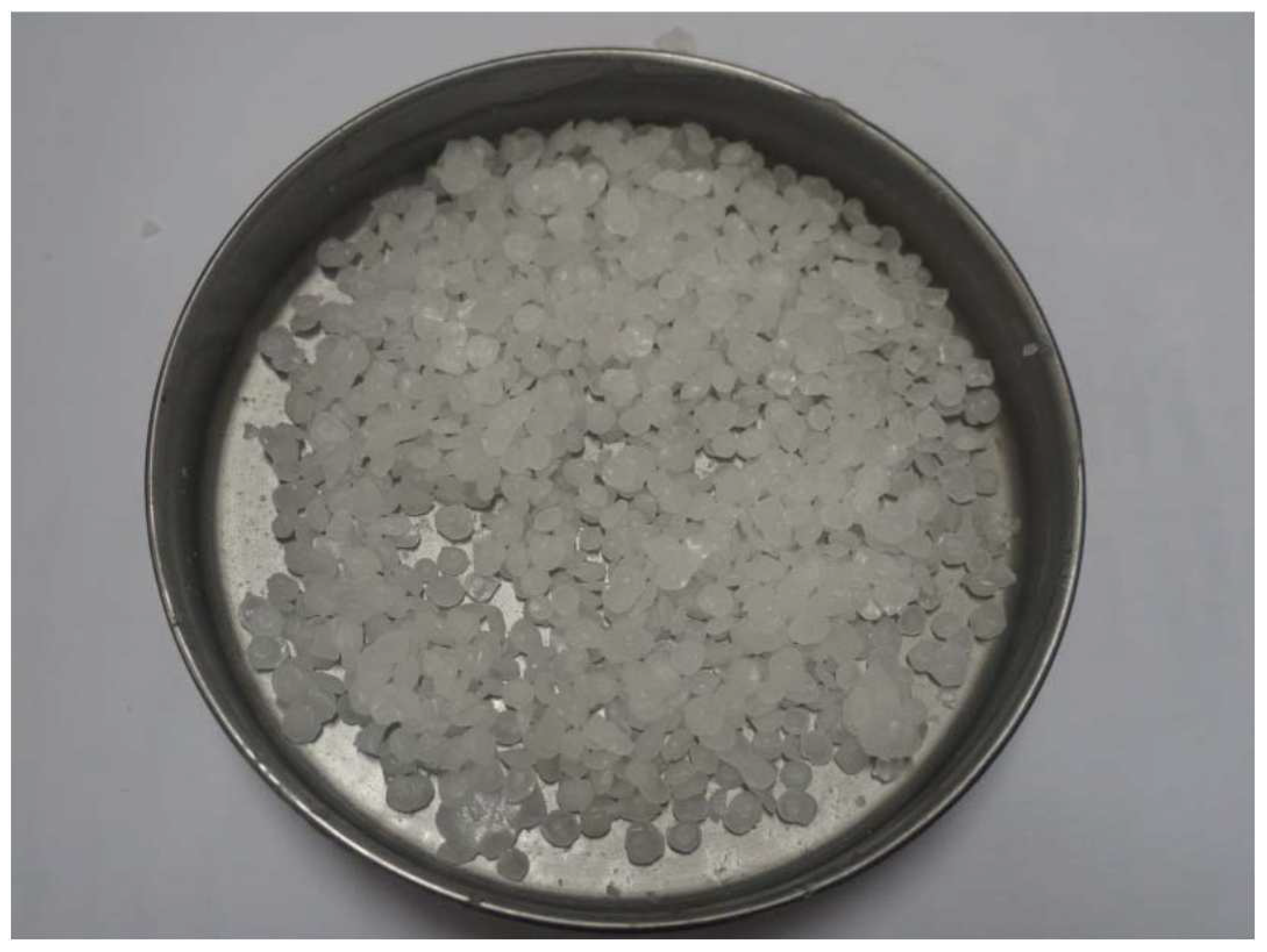
Since the potential use of PCMs in various thermal storage applications is quite limited by their cost, it is very important to choose the appropriate PCM heat storage material in the vacuum tube. According to the existing research, fully refined No. 58 paraffin is the outstanding thermal storage material. The paraffin entity is shown in Figure 2 and the thermo-physical properties of paraffin are listed in Table 1.
The amount of paraffin to be inserted and the packaging method are of vital importance. As there is only 5 mm between the outer edge of the tube’s radial fin and the inner diameter of the vacuum glass tube, it is difficult to ensure that the paraffin can be instilled to the bottom of the vacuum tube. It is also difficult to ensure that the paraffin can completely occupy the space between the fins and the vacuum tubes. In light of this problem, an unconventional method has been proposed to ensure the filling amount of paraffin wax. In this experiment, the paraffin particles are first heated and melted into liquid. Then, the paraffin is placed in a metal container for cooling and solidification. After this step, the wax is injected into the gap between the fins when it has not cured completely, as is shown in Figure 3. In the next step, the U-tube filled with paraffin is placed into the glass vacuum tube and the energy storage vacuum tube collector is placed outdoors to absorb solar radiation until the paraffin melts and takes up the space between the inner surface of the U tube and the glass vacuum tube. Finally, the liquid paraffin is added into the vacuum tube until the glass tube is closed. Before filling the tube with paraffin, the mass of the single vacuum glass tube measured is 8.80 kg, and the mass of the U tube with metal fins is 4.80 kg. After filling the tube with paraffin, the whole mass of the vacuum tube is 22.6 kg. Thus, the mass of paraffin actually inserted is 9 kg.
Another point should be stressed: the open end of the vacuum tube needs to be sealed and insulated. In this experiment, the Expandable Polyethylene (EPE) pearl cotton is used as package material. The EPE pearl cotton is made up of a large number of independent bubbles produced by physical foaming of low density polyethylene. Due to the makeup of EPE pearl cotton, it has the following characteristics: moisture proof, heat preservation, good plasticity, strong flexibility, chemical resistance and flame retardant. Finally, the rubber materials are placed outside the EPE pearl cotton for insulation.
2.2. Experimental Apparatus and Experimental Platform
The construction of the experimental platform is the most important part of the whole experiment, since the quality of the platform directly affects the reliability of the experimental results. The experiment will study the actual operating conditions of the energy storage vacuum tube heat collector in daytime and nighttime. The experimental medium is ordinary tap water supplied by a municipal pipe network. The experiment is performed to obtain the parameters of the inlet and outlet water temperature and water flow of the U type copper pipe inside the heat collector. The thermal energy absorbed by the heat collector is calculated to analyze the feasibility and practicability of the novel-type phase change energy storage vacuum heat collector. The schematic diagram of experimental apparatus used in the test is shown in Figure 4.
The apparatus used in this experiment mainly includes a solar radiation illuminance tester, a rotor flow meter, an anemometer, a data acquisition machine and several T-type thermocouples. A summary of the experimental setup is listed in Table 2 and the categories of the experimental running times are listed in Table 3. Photos taken from the experimental setup during the testing are shown in Figure 5.
3. Error Analysis of Measurement System
The errors of this experiment mainly include systematic error and random error. The characteristic of the system error is that the value is kept constant which is caused by the fixed factors and varies with the experimental conditions. The system error of this experiment is mainly caused by the loose seal of the vacuum collector port (the actual heat loss is considered to be adiabatic in the experiment). Random error, the characteristic of which is that the value varies without fixed bias and obeys the statistical law, is caused by uncertain factors. The random errors in this experiment include the measurement error of the inlet and outlet water temperature, water flow rate and the temperature inside the vacuum tube.
The relative error is used in this experiment to directly measure the confidence level of the data. The sum of the calibration error of the thermocouple and the acquisition system error is 0.4 °C. The minimum temperature of paraffin wax being measured in this experiment is 12 °C. The maximum relative error of the temperature measurement is 0.4/12 = 3.33%. The maximum measurement error of the flow rate is 1.5 L/h. The minimum flow rate being measured is 20 L/h. The maximum relative error of the water flow measurement is 1.5/20 = 7.5%.
4. Result and Discussion
4.1. Working Condition in Daytime of Transitional Season
Figure 6 shows the transient solar radiation intensity in daytime. As can be seen from Figure 6, the solar radiation was strong on that day. The maximum radiation appeared during the daytime between 12:00 and 13:00, up to 850 W/m2. The radiation value rose steadily in the morning. There were nearly 200 W/m2 fluctuations at 11:30. The radiation value was very small after 16:00 and was below 100 W/m2. Figure 7 shows the change of outdoor air temperature with time in daytime. From Figure 7, we can see that the peak temperature reached 33 °C and the lowest outdoor temperature was 18 °C. The average air temperature during the daytime was 27 °C.
The temperature variations of different position during the period of accumulating solar energy are shown in Figure 8 to explore the heating effect induced by PCM on the water inside the U-tube. As is shown by the graph, the paraffin had not yet melted by 09:00. Then, the top part of the paraffin, facing the sun, went into the molten state and the temperature climbed slowly. At the same time, the temperature of the paraffin inside and at the bottom of the tube was still rising. After 10:40, the paraffin on the top completely melted into liquid and the slope of the temperature curve increased obviously. As a result, the temperature of the paraffin on the top was much higher than that of the paraffin in the middle and at the bottom of the tube. At 11:00, the paraffin in the middle of the tube turned into the molten state. At 11:30, the paraffin at the bottom of the tube entered into the molten state. Due to the natural convection, the heat transfer inside the tube was enhanced. The paraffin temperature difference between the middle and bottom was decreasing after the paraffin had melted. Here, the amount of heat absorbed by PCM in the daytime of the transitional season is estimated to be 2666.2 kJ.
4.2. Working Condition at Night of Transitional Season
In order to analyze the exothermic characteristics and practicability of the new PCM energy storage vacuum tube heat collector, an experiment has been carried out on its operation conditions at night. At about 19:00 in the evening, the temperature distributions of paraffin in the vacuum tube were nearly the same. The municipal pipe network water supply was linked to the inlet of the U-tube. The water inlet temperature was 17 °C, with a fluctuation range of −0.5 °C to 0.5 °C after measurement. The water supply went through the U-type pipe and exchanged heat with the paraffin. During the heat transfer process, the temperature of the outlet water was declining continuously.
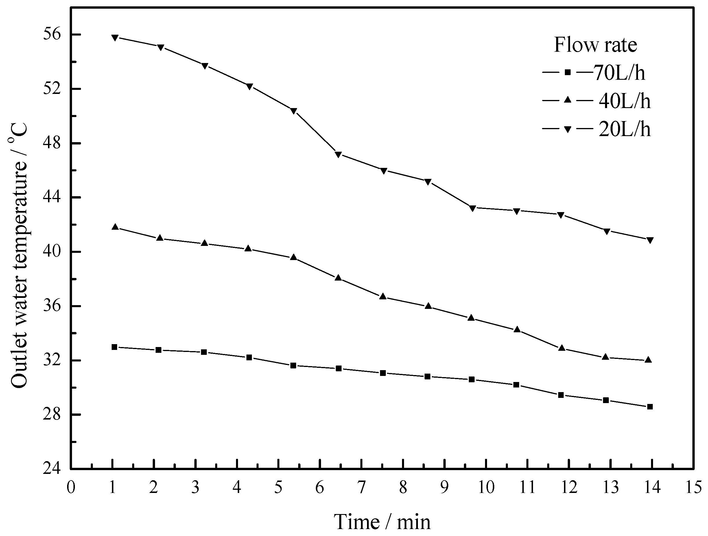
As is shown in Figure 9, when the paraffin was in the solidification and heat release stage, the outlet water temperature changes of the U-type copper tube were 41.5 °C~55.9 °C (flow rate 20 L/h), 32.9 °C~42.4 °C (flow rate 40 L/h), 29.5 °C~33.7 °C (flow rate 70 L/h). As the flow increased, the heat transfer time between the water in the tube and paraffin outside the tube slowed down. As a result, the outlet water temperature of the U-type copper tube continued to decline. In this experiment, the paraffin temperature was 58 °C and remained unchanged. When the flow rate was 20 L/h and 40 L/h, the velocity of flow was 0.071 m/s and 0.144 m/s respectively. By calculating the Reynolds number, the fluid in the tube was in laminar flow. When the flow rate was 70 L/h, the flow was in a turbulent state, which enhanced the heat transfer effect.
4.3. Working Condition in Daytime of Summer Season
As is shown in Figure 10 and Figure 11, experiments were conducted to evaluate the performances of the new PCM energy storage vacuum tube heat collector for two typical days during the period of August 2016. Figure 10 illustrates a sunny day with higher solar radiation and lower outdoor temperature. On the contrary, Figure 11 illustrates a day with lower solar radiation and higher outdoor temperature. Figure 10 and Figure 11 show that the factor of solar radiation has a greater influence on the temperature of the heat collector than that of ambient temperature during the charging process. In Figure 10, the highest collector temperature achieved is about 67 °C. Yet, the highest collector temperature achieved is about 52 °C in Figure 11. From Figure 10, it is observed that the temperature rose fastest during the time period of 14:35–15:00. This can also be confirmed by Figure 11. When the average solar irradiation amount is 672 W/m2, the amount of heat absorbed by PCM in the daytime of the summer season is estimated to be 3300 kJ. When the average solar irradiation amount is 615 W/m2, the amount of heat absorbed by PCM in the daytime of the summer season is estimated to be 2934 kJ.
Figure 12 depicts the outlet temperature variation during the discharging process. The outlet temperature is 58 °C when the water valve is closed. The transitory flow goes into the U-tube and out after a short period of heat transfer. The heat transfer equilibrium stage is reached and the PCM is fully discharged when the outlet temperature drops to a substantially constant value. During the discharging period, when the flow rate is 35 L/h, it takes 10 min to achieve the heat exchange balance. When the flow rate is 100 L/h, it takes 3 min to achieve the heat exchange balance. It could be noted that the ratio of the flow rate change is inversely proportional to the equilibrium time ratio.
4.4. Working Condition at Night of Summer Season
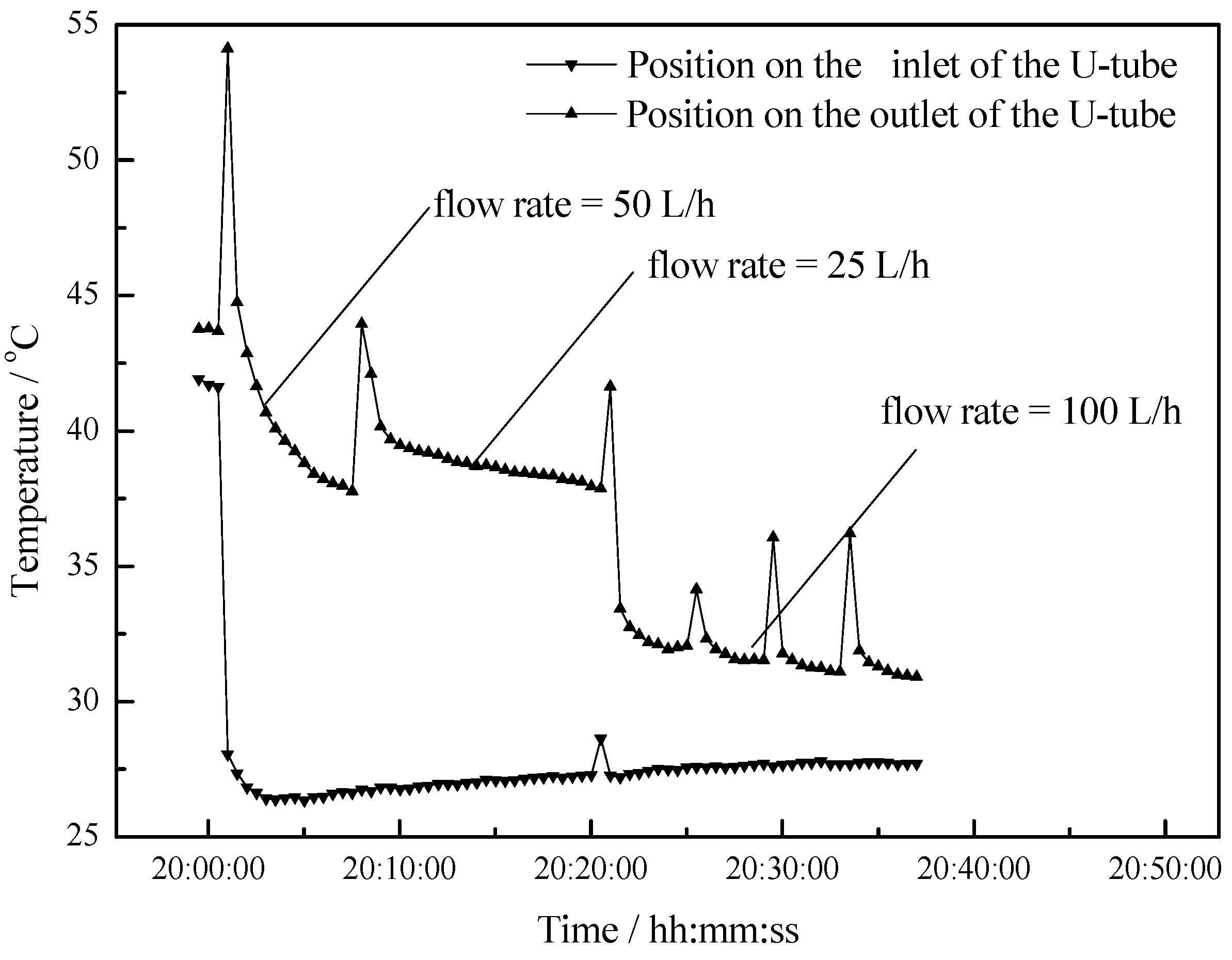
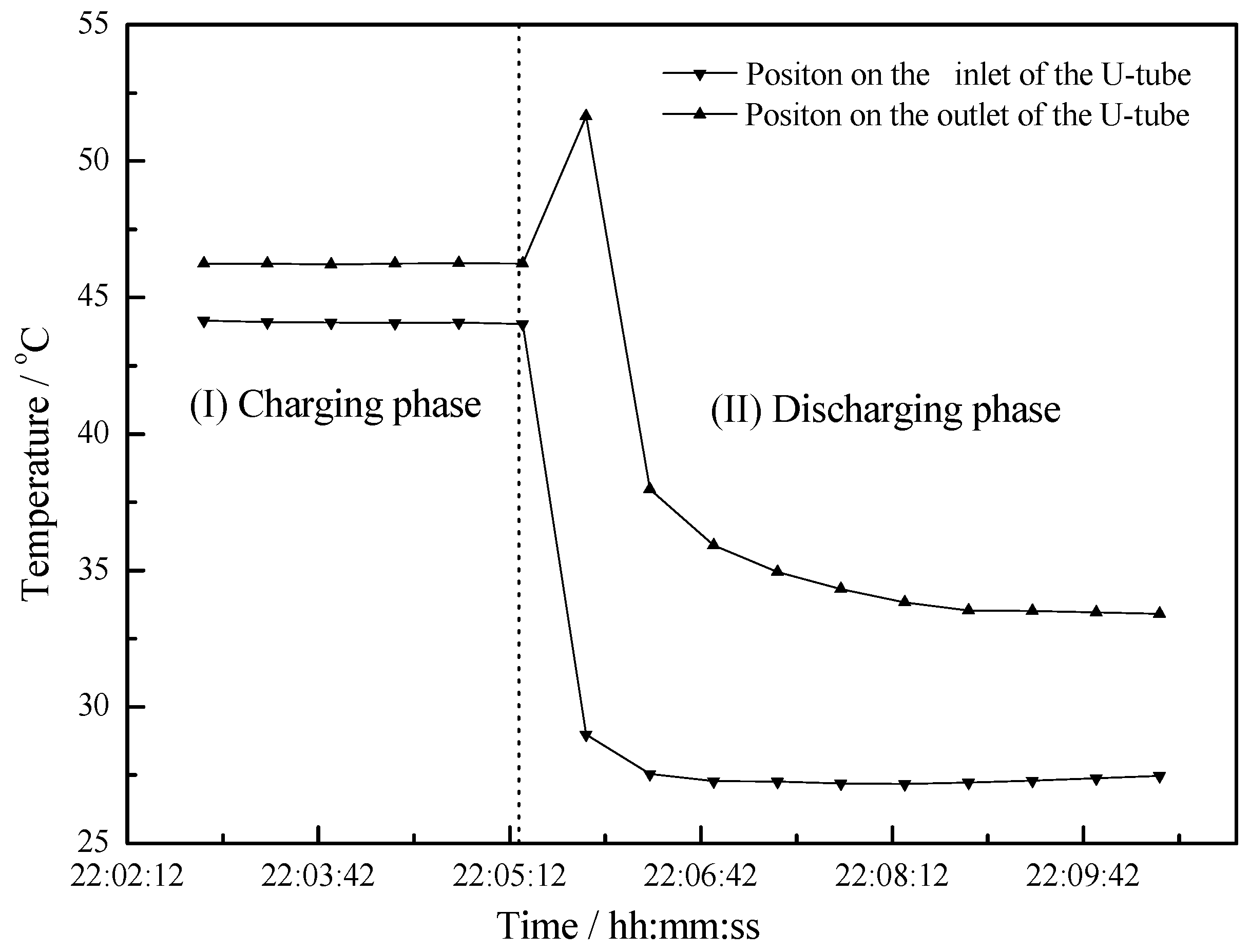
The inlet and outlet water temperature distribution is presented in Figure 13. The water temperature is measured by two thermocouples inserted inside the U-tube (Figure 4). Figure 13 demonstrates two stages in the evening: the charging stage and the discharging stage. Since the water inlet is positioned on the back face and the water outlet is positioned on the side facing the sun, the outlet temperature is slightly higher than the inlet temperature during the charging phase. It is obvious that during the discharging process at night, the liquid PCM starts solidifying and the used heat is uniform for a long period. During the evening hours and the discharging process, the outlet temperature exceeds the inlet temperature with differences of at least 8 °C. This is the major advantage of the vacuum tube collector with an integrated latent storage unit, where a uniform discharging process is possible for a long period. As is shown in Figure 13 and Figure 14, the outlet water temperature rises steeply at the beginning of the discharging phase.
Figure 14 shows the water temperature variations under different flow rates. The inlet water temperature is around 27 °C and the outlet water temperature is observed at 44 °C in the initial state. After 8 min, the outlet water temperature is approximately 37 °C and the first heat exchange balance is achieved. During the discharging period, the flow rate is 50 L/h, 25 L/h and 100 L/h, and the temperature differences between the outlet water and inlet water are 10 °C, 11 °C and 5 °C. It can be concluded that as the flow rate decreases, the temperature difference increases, but the changing rate of the temperature difference is becoming slower.
5. Conclusions
The thermal behavior of a novel energy storage vacuum tube collector has been experimentally investigated. Paraffin has been proven to be a good choice for the application of solar storage, due to its easy workability, its melting temperature, its high latent capacity and its availability. The phase transition temperature of paraffin is 58 °C, which is suitable for night time application.
The primary objective of this study was to develop the energy storage vacuum tube collector. Subsequently, the operation conditions of transition season and summer for the solar storage water system were studied. Finally, the inlet and outlet water temperature of the system were analyzed at different flow rates.
Results obtained for the energy storage vacuum tube collector with different flow rates of HTF are summarized here.
- (1)
- The paraffin phase transformation occurs on sunny days of the transition season and summer. It can be found that the maximum hot water temperature reaches 67 °C and 53 °C with the average solar irradiation amount of 672 W/m2 and 615 W/m2 respectively in summer. Solar radiation has a greater influence on the temperature of the heat collector than ambient temperature during the charging process.
- (2)
- The amount of heat absorbed by PCM in the daytime of the summer season reaches 3300 kJ and 2934 KJ with the average solar irradiation amount of 672 W/m2 and 615 W/m2 respectively in summer. It can also be concluded that, as the solar radiation increases, the heat absorbed by the PCM also increases.
- (3)
- The maximum temperature difference reaches 11 °C, 10 °C and 5 °C at flow rates of 25 L/h, 50 L/h and 100 L/h respectively. As the flow rate increases, the outlet water temperature of the U-type copper tube decreases. As the flow rate decreases, the temperature difference between the outlet water and inlet water increases, but the changing rate of temperature difference is becoming slower.
- (4)
- Due to the heat stored in the PCM, a uniform discharging process takes a long time which provides more comfortable hot water application.
Acknowledgments
The presented work was supported by the Research Funds of Key Laboratory of Heating and Air Conditioning, The Education Department of Henan Province; National Natural Science Foundation of China (Grant No. 50776015) and National Natural Science Foundation of China (Grant No. 51606037).
Author Contributions
Zhenqian Chen and Juan Shi conceived and designed the experiment; Xinpeng Huang performed the experiments and analyzed the data; Xinpeng Huang wrote the paper.
Conflicts of Interest
The authors declare no conflict of interest.
References
- Khodadadi, J.M.; Hosseinizadeh, S.F. Nanoparticle-enhanced phase change materials (NEPCM) with great potential for improved thermal energy storage. Int. Commun. Heat Mass Transf. 2007, 34, 534–543. [Google Scholar] [CrossRef]
- Elgafy, A.; Lafdi, K. Effect of carbon nanofiber additives on thermal behavior of phase change materials. Carbon 2005, 43, 3067–3074. [Google Scholar] [CrossRef]
- Tiari, S.; Qiu, S.; Mahdavi, M. Numerical study of finned heat pipe-assisted thermal energy storage system with high temperature phase change material. Energy Convers. Manag. 2015, 89, 833–842. [Google Scholar] [CrossRef]
- Sharifi, N.; Bergman, T.L.; Allen, M.J.; Faghri, A. Melting and solidification enhancement using a combined heat pipe, foil approach. Int. J. Heat Mass Transf. 2014, 78, 930–941. [Google Scholar] [CrossRef]
- Eftekhar, J.; Hajisheikh, A.; Lou, D. Heat-transfer enhancement in a paraffin wax thermal storage-system. J. Sol. Energy Eng. 1984, 106, 299–306. [Google Scholar] [CrossRef]
- Zalba, B.; Marin, J.M.; Cabeza, L.F. Review on thermal energy storage with phase change: Materials, heat transfer analysis and applications. Appl. Therm. Eng. 2003, 23, 251–283. [Google Scholar] [CrossRef]
- Yazici, M.Y.; Avci, M.; Aydin, O. Effect of eccentricity on melting behavior of paraffin in a horizontal tube-in-shell storage unit: An experimental study. Sol. Energy 2014, 101, 291–298. [Google Scholar] [CrossRef]
- Reyes, A.; Henriquez-Vargas, L.; Aravena, R. Experimental analysis, modeling and simulation of a solar energy accumulator with paraffin wax as PCM. Energy Convers. Manag. 2015, 105, 189–196. [Google Scholar] [CrossRef]
- Kumar, R.A.; Babu, B.G.; Mohanraj, M. Thermodynamic performance of forced convection solar air heaters using pin-fin absorber plate packed with latent heat storage materials. J. Therm. Anal. Calorim. 2016, 126, 1657–1678. [Google Scholar] [CrossRef]
- Padmanabhan, P.V.; Murthy, M.V.K. Outward phase-change in a cylindrical annulus with axial fins on the inner tube. Int. J. Heat Mass Transf. 1986, 29, 1855–1868. [Google Scholar] [CrossRef]
- Zhang, P.; Meng, Z.N.; Zhu, H. Melting heat transfer characteristics of a composite phase change material fabricated by paraffin and metal foam. Appl. Energy 2017, 185, 1971–1983. [Google Scholar] [CrossRef]
- Yang, J.; Yang, L.; Xu, C. Experimental study on enhancement of thermal energy storage with phase-change material. Appl. Energy 2016, 169, 164–176. [Google Scholar] [CrossRef]
- Xiao, X.; Zhang, P. Numerical and experimental study of heat transfer characteristics of a shell-tube latent heat storage system: Part I—Charging process. Energy 2015, 79, 337–350. [Google Scholar] [CrossRef]
- Xiao, X.; Zhang, P. Numerical and experimental study of heat transfer characteristics of a shell-tube latent heat storage system: Part II—Discharging process. Energy 2015, 80, 177–189. [Google Scholar] [CrossRef]
- Baby, R.; Balaji, C. Experimental investigations on thermal performance enhancement and effect of orientation on porous matrix filled PCM based heat sink. Int. Commun. Heat Mass Transf. 2013, 46, 27–30. [Google Scholar] [CrossRef]
- Reddy, K.S. Thermal modeling of PCM-based solar integrated collector storage water heating system. J. Sol. Energy Eng. 2007, 129, 458–464. [Google Scholar] [CrossRef]
- Mahfuz, M.H.; Anisur, M.R.; Kibria, M.A. Performance investigation of thermal energy storage system with Phase Change Material (PCM) for solar water heating application. Int. Commun. Heat Mass Transf. 2014, 57, 132–139. [Google Scholar] [CrossRef]
- Murali, G.; Mayilsamy, K. Effect of Latent Thermal Energy storage and inlet locations on enhancement of stratification in a solar water heater under discharging mode. Appl. Therm. Eng. 2016, 106, 354–360. [Google Scholar] [CrossRef]
- Sakhrieh, A.; Abdullat, Y.; Hamdan, M.A. Enhancement of Thermal Energy Storage Using Phase-Change Material under Jordanian Climate. J. Infrastruct. Syst. 2016, 22, A40140011–A40140015. [Google Scholar] [CrossRef]
- El Khadraoui, A.; Bouadila, S.; Kooli, S. Solar air heater with phase change material: An energy analysis and a comparative study. Appl. Therm. Eng. 2016, 107, 1057–1064. [Google Scholar] [CrossRef]
Figure 1.
U type tube and fin profile.
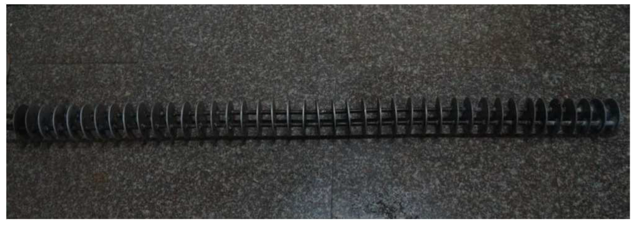
Figure 2.
Fully refined No. 58 paraffin granules.

Figure 3.
U-tube prefilled with paraffin.

Figure 4.
Schematic diagram of experimental apparatus.
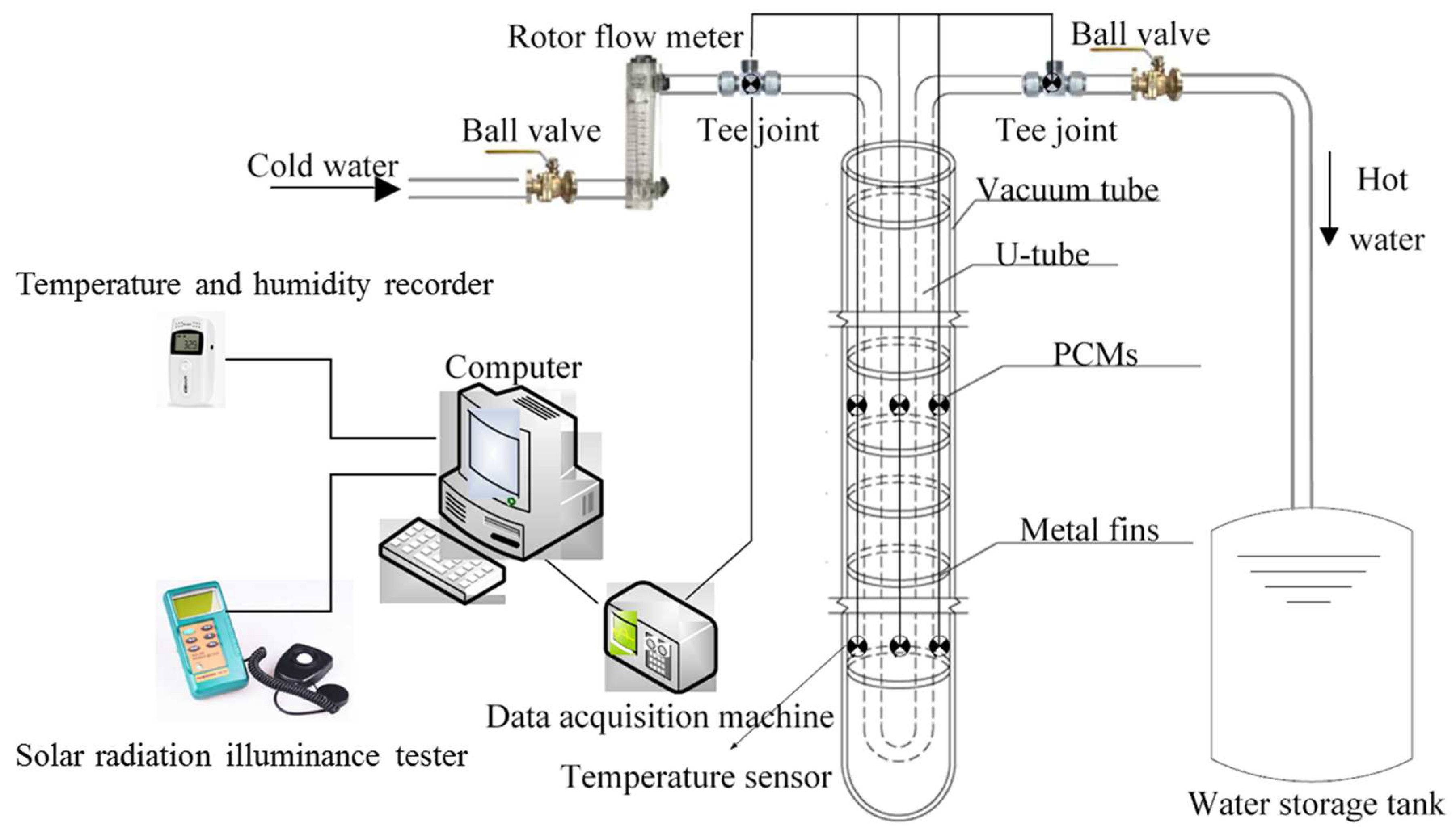
Figure 5.
Photos of the experimental platform during daytime.
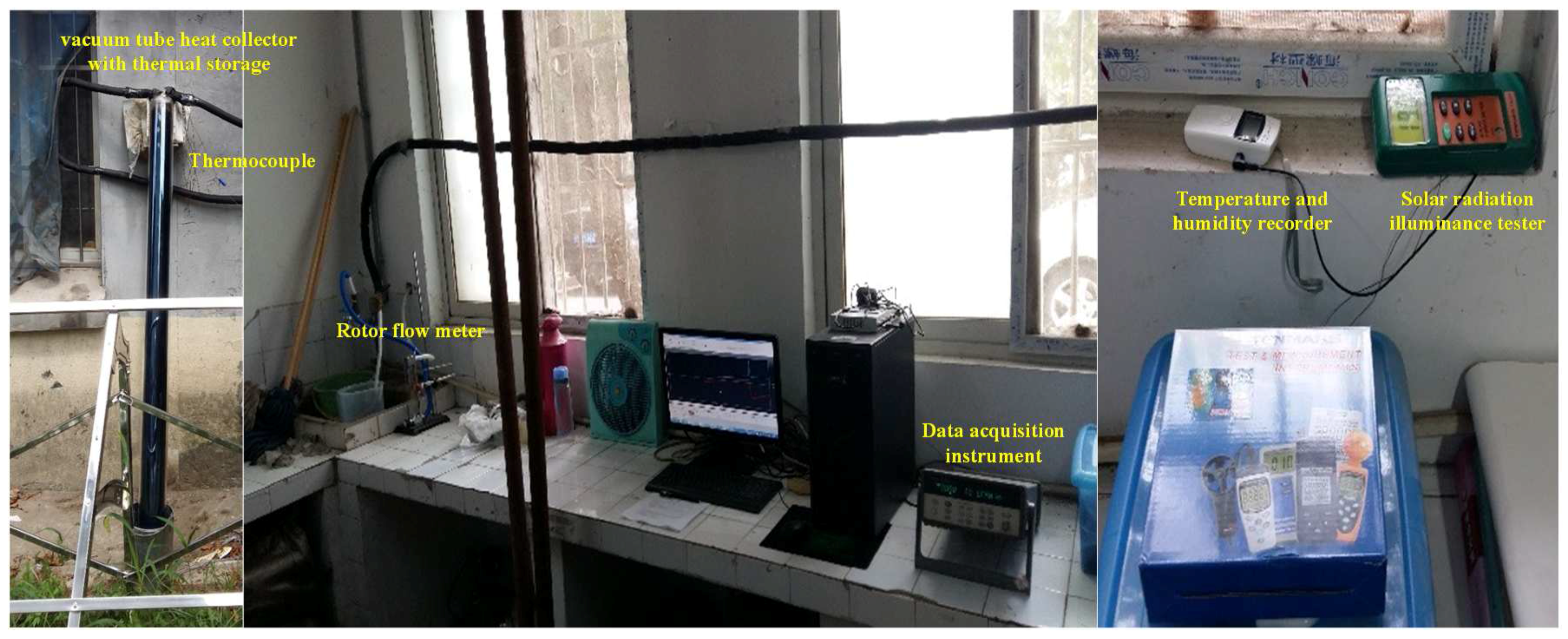
Figure 6.
Solar radiation changes over time.

Figure 7.
Outdoor air temperature versus time.

Figure 8.
Paraffin temperature versus time by daylight.

Figure 9.
Outlet water temperature versus time at night.

Figure 10.
Water temperature versus time by daylight.
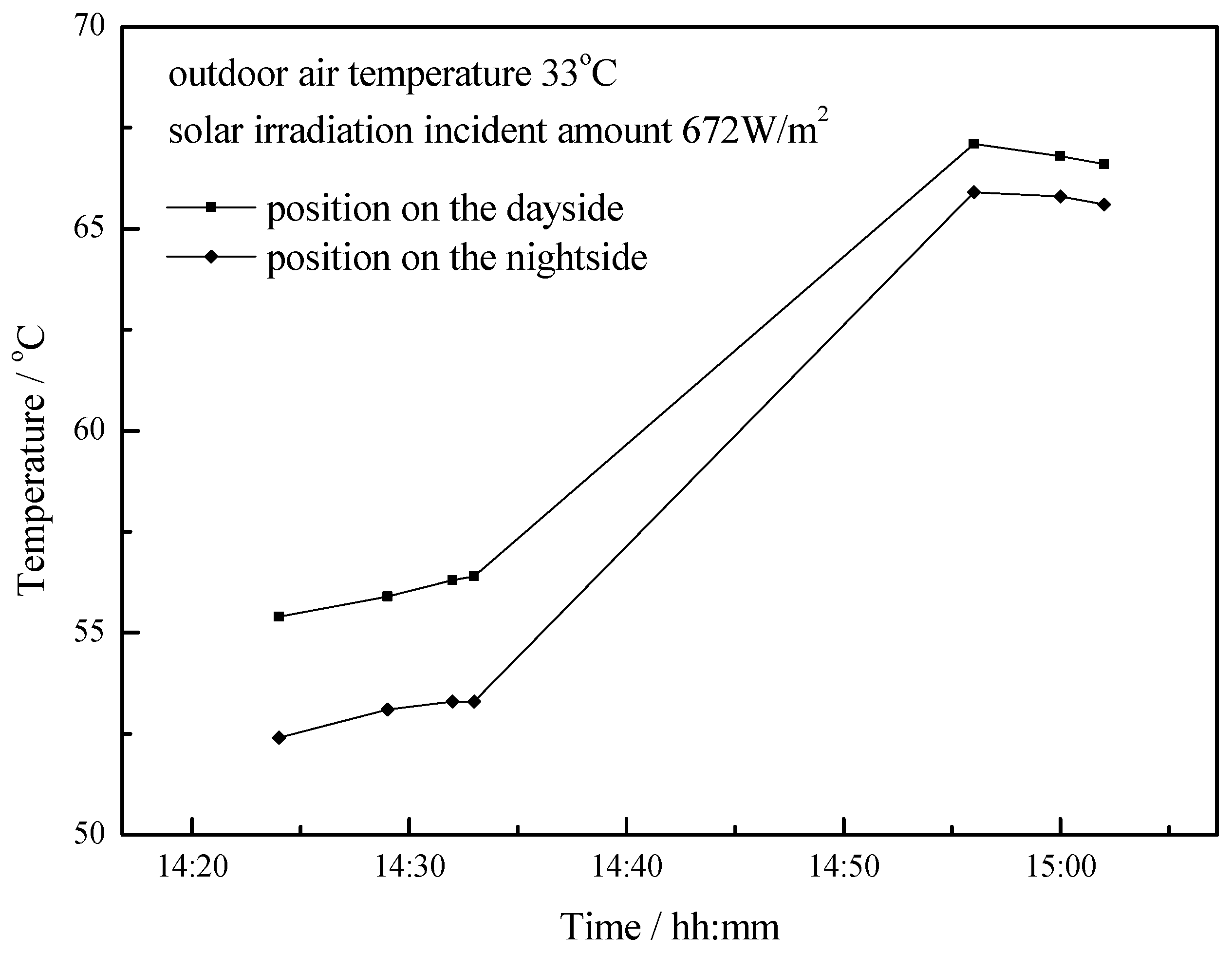
Figure 11.
Water temperature versus time by daylight.
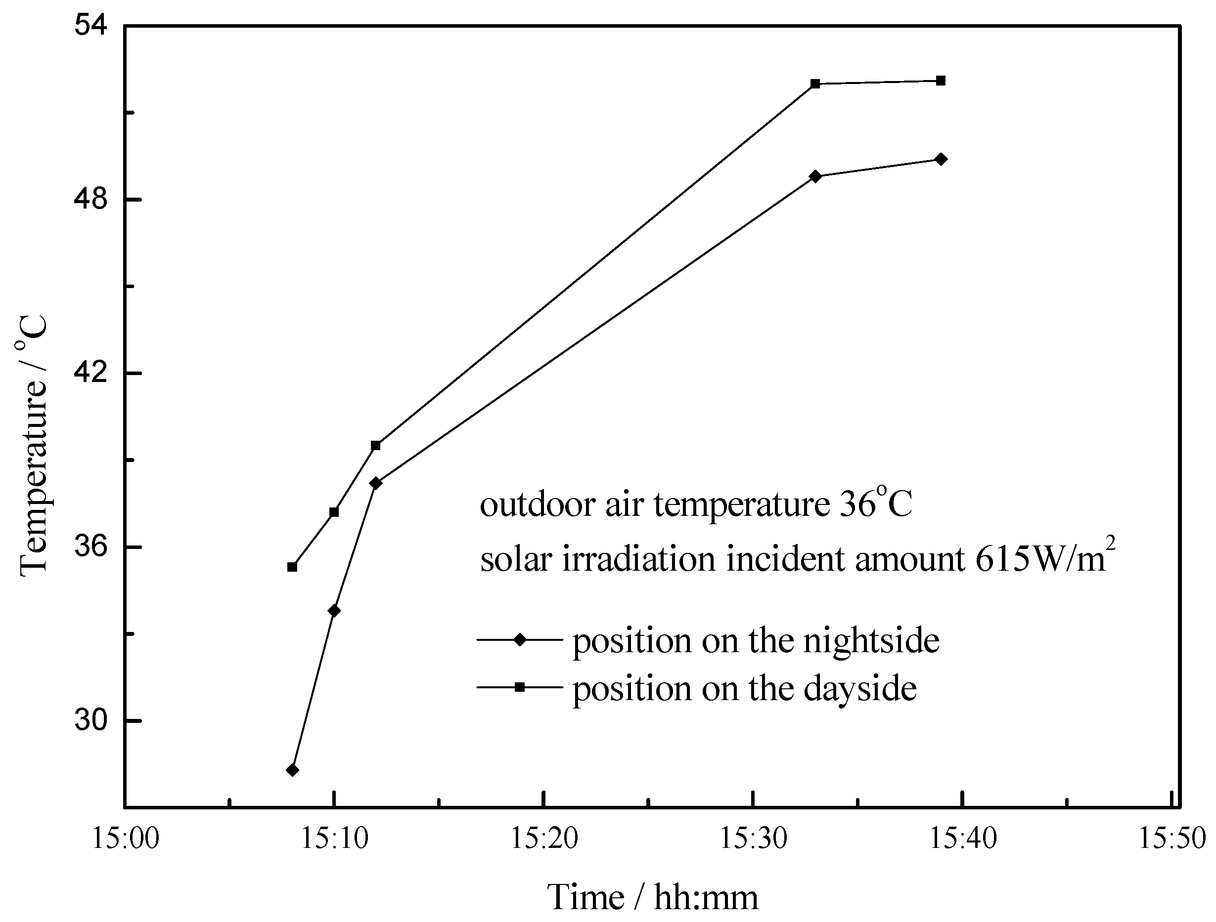
Figure 12.
Outlet water temperature versus time during the daytime in summer.
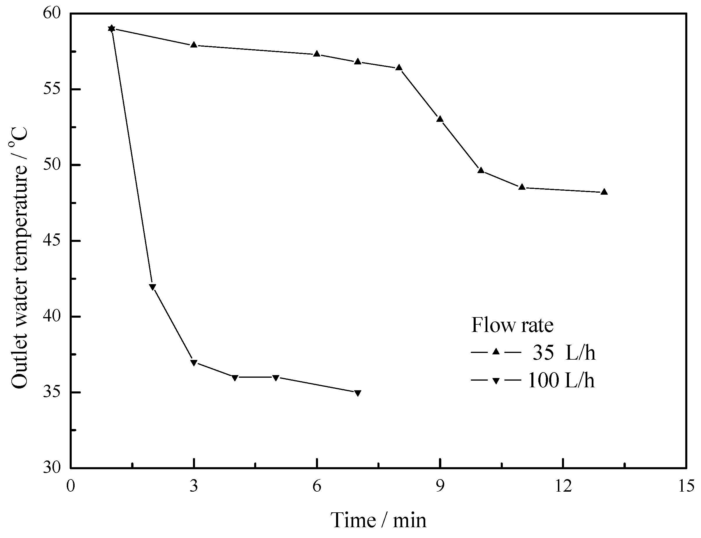
Figure 13.
Water temperature versus time at night in summer (flow rate = 100 L/h).

Figure 14.
Water temperature versus time at night in summer with different flow rates.

Table 1.
The thermo-physical properties of paraffin.
| No. | Physical Properties | Unit | Value |
|---|---|---|---|
| 1 | Specific heat C | J/(kg·K) | 3350 (solid)/2700 (liquid) |
| 2 | Thermal conductivity k | W/(m·K) | 0.35 (solid)/0.15 (liquid) |
| 3 | Density ρ | kg/m3 | 920 (solid)/795 (liquid) |
| 4 | Latent heat H | kJ/kg | 158.2 |
| 5 | Phase-transition temperature | °C | 55~61 |
Table 2.
Experimental apparatus.
| Name | Type and Specification | Measuring Range and Measuring Frequency | Accuracy |
|---|---|---|---|
| Data acquisition instrument | Agilent 34970A | up to 60 channels per second | - |
| Solar radiation illuminance tester | TENMARS TM-207 | 0~2000 W/m2 | 7~12 μV/W·m2 |
| Anemometer | FS-R4-30 | 0~30 m/s | 0.5 m/s |
| Rotor flow meter | JUNHAI LZB-10 | 10~100 L/h | 1.5 level |
| Thermocouple | T-type (copper-constantan) | −40 °C~200 °C | 0.2 °C |
Table 3.
Experimental time period.
| Testing Stage Name | Period |
|---|---|
| Water filling stage | 7:00~7:30 |
| Heat accumulation and heat preservation stage | 7:30~19:00 |
| Heat release stage | 19:00~20:00 |
© 2017 by the authors. Licensee MDPI, Basel, Switzerland. This article is an open access article distributed under the terms and conditions of the Creative Commons Attribution (CC BY) license (http://creativecommons.org/licenses/by/4.0/).
Share and Cite
MDPI and ACS Style
Huang, X.; Chen, Z.; Shi, J. Experimental Study on Heat Transfer Performance of Vacuum Tube Heat Collector with Thermal Storage. Appl. Sci. 2017, 7, 448. https://doi.org/10.3390/app7050448
AMA Style
Huang X, Chen Z, Shi J. Experimental Study on Heat Transfer Performance of Vacuum Tube Heat Collector with Thermal Storage. Applied Sciences. 2017; 7(5):448. https://doi.org/10.3390/app7050448
Chicago/Turabian StyleHuang, Xinpeng, Zhenqian Chen, and Juan Shi. 2017. "Experimental Study on Heat Transfer Performance of Vacuum Tube Heat Collector with Thermal Storage" Applied Sciences 7, no. 5: 448. https://doi.org/10.3390/app7050448
Note that from the first issue of 2016, this journal uses article numbers instead of page numbers. See further details here.