
Construction and Commissioning of PAL-XFEL Facility
by
 ,
,
In Soo Ko
*, 
Heung-Sik Kang
,
Hoon Heo
,
Changbum Kim
,
Gyujin Kim
,
Chang-Ki Min
,
Haeryong Yang
,
Soung Youl Baek
,
Hyo-Jin Choi
,
Geonyeong Mun
,
Byoung Ryul Park
,
Young Jin Suh
,
Dong Cheol Shin
,
Jinyul Hu
,
Juho Hong
,
Seonghoon Jung
,
Sang-Hee Kim
,
KwangHoon Kim
,
Donghyun Na
,
Soung Soo Park
,
Yong Jung Park
,
Young Gyu Jung
,
Seong Hun Jeong
,
Hong Gi Lee
,
Sangbong Lee
,
Sojeong Lee
,
Bonggi Oh
,
Hyung Suck Suh
,
Jang-Hui Han
,
Min Ho Kim
,
Nam-Suk Jung
,
Young-Chan Kim
,
Mong-Soo Lee
,
Bong-Ho Lee
,
Chi-Won Sung
,
Ik-Su Mok
,
Jung-Moo Yang
,
Yong Woon Parc
,
Woul-Woo Lee
,
Chae-Soon Lee
,
Hocheol Shin
,
Ji Hwa Kim
,
Yongsam Kim
,
Jae Hyuk Lee
,
Sang-Youn Park
,
Jangwoo Kim
,
Jaeku Park
,
Intae Eom
,
Seungyu Rah
,
Sunam Kim
,
Ki Hyun Nam
,
Jaehyun Park
,
Jaehun Park
,
Sangsoo Kim
,
Soonnam Kwon
,
Ran An
,
Sang Han Park
,
Kyung Sook Kim
,
Hyojung Hyun
,
Seung Nam Kim
,
Seonghan Kim
,
Chung-Jong Yu
,
Bong-Soo Kim
,
Tai-Hee Kang
,
Kwang-Woo Kim
,
Seung-Hwan Kim
,
Hee-Seock Lee
,
Heung-Soo Lee
,
Ki-Hyeon Park
,
Tae-Yeong Koo
,
Dong-Eon Kim
and
Ki Bong Lee
add
Show full author list
Pohang Accelerator Laboratory, POSTECH, Pohang 37673, Korea
*
Author to whom correspondence should be addressed.
Appl. Sci. 2017, 7(5), 479; https://doi.org/10.3390/app7050479
Submission received: 23 March 2017
/
Revised: 20 April 2017
/
Accepted: 26 April 2017
/
Published: 17 May 2017
(This article belongs to the Special Issue X-Ray Free-Electron Laser)
Abstract
:The construction of Pohang Accelerator Laboratory X-ray Free-Electron Laser (PAL-XFEL), a 0.1-nm hard X-ray free-electron laser (FEL) facility based on a 10-GeV S-band linear accelerator (LINAC), is achieved in Pohang, Korea by the end of 2016. The construction of the 1.11 km-long building was completed by the end of 2014, and the installation of the 10-GeV LINAC and undulators started in January 2015. The installation of the 10-GeV LINAC, together with the undulators and beamlines, was completed by the end of 2015. The commissioning began in April 2016, and the first lasing of the hard X-ray FEL line was achieved on 14 June 2016. The progress of the PAL-XFEL construction and its commission are reported here.
1. Introduction
The Pohang Accelerator Laboratory X-ray Free-Electron Laser (PAL-XFEL) project was started in 2011 for the generation of X-ray FEL radiation in a range of 0.1 to 10 nm for users. The Korean government launched the project on 1 April 2011 with a budget of 400 billion Won (~400 million USD). The facility has the capacity for five undulator lines in total; three hard X-ray (HX) undulator lines and two soft X-ray (SX) undulator lines. However, the budget was limited to two undulator lines; one for a hard, and the other for a soft X-ray line. Since the PAL is the host institution carrying out the project, the project budget was able to avoid significant costs; for example, there was no need to purchase the land for the building site and a significant portion of the necessary infrastructures, such as power transmission lines and substations, were already in place. A total of 75 members were involved during the project. Among them, there were 35 newly hired members and 39 experienced members from an existing Pohang Light Source-II (PLS-II) team. A yearly budget is shown in Table 1.
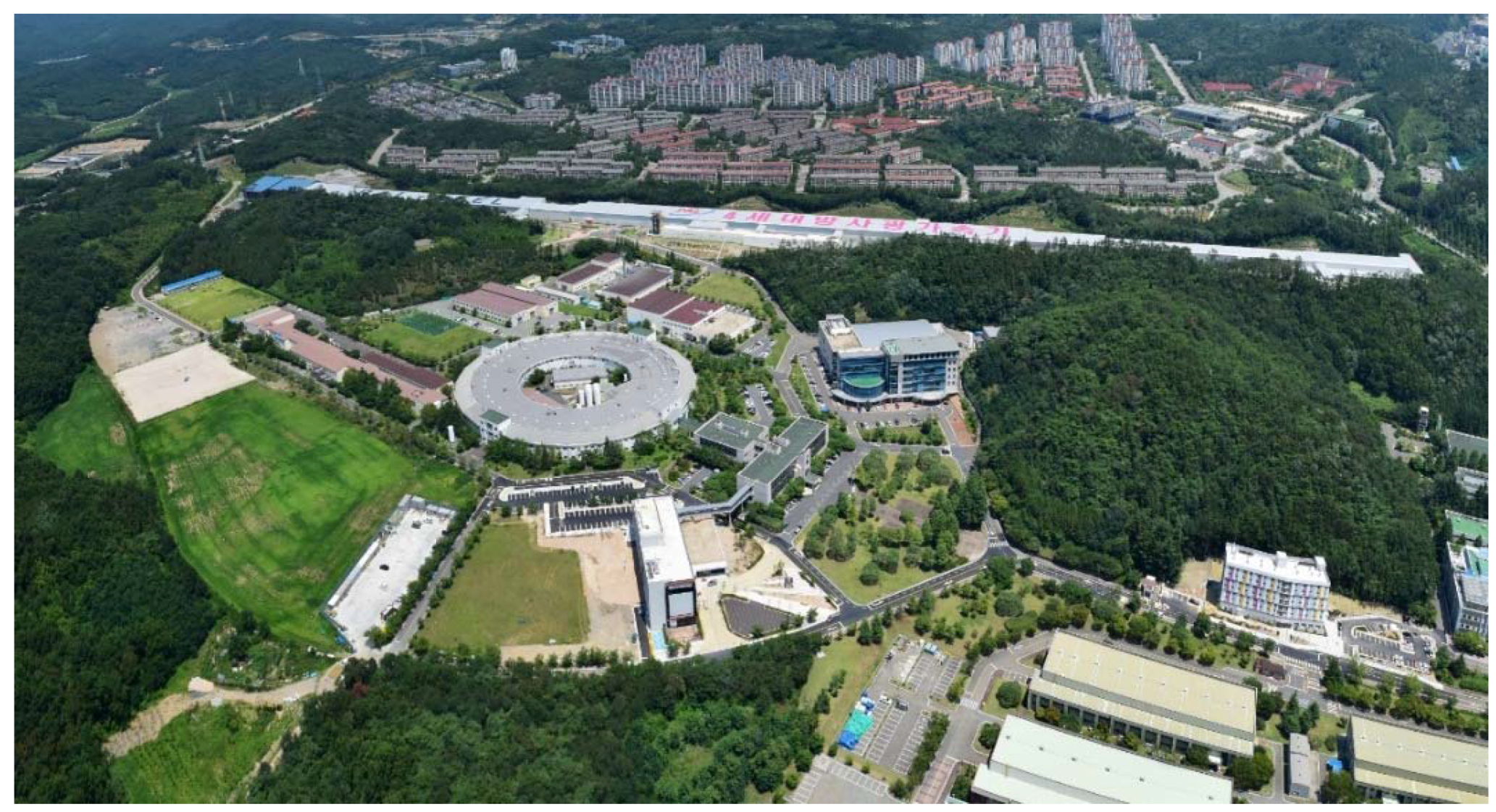
PAL-XFEL includes a 10-GeV S-band (2856 MHz) normal-conducting LINAC, which is about 700 m long. The LINAC consists of a photocathode RF gun, 176 S-band accelerating structures with 50 klystrons and matching modulators, one X-band RF system for linearization, and three bunch compressors in the HX line and one more for the SX line [1]. We also chose out-vacuum/variable-gap undulators for the easy change of beam parameters, and the fast development and manufacturing of undulators. Beyond the 10-GeV LINAC, a 250-m long hard X-ray undulator hall follows. An experimental hall, which is 60 m long and 16 m wide, is located at the end of the facility. The total length of the building is 1110 m, and the entire floor is 36,764 m2. The building can withstand a maximum wind load of 63 m/s (US building code) and a seismic intensity of 0.19-g [2]. The facility suffered no damage from the earthquake of a 5.8 magnitude on 12 September 2016, nor from the typhoon Chava on 5 October 2016. The facility is shown in Figure 1.
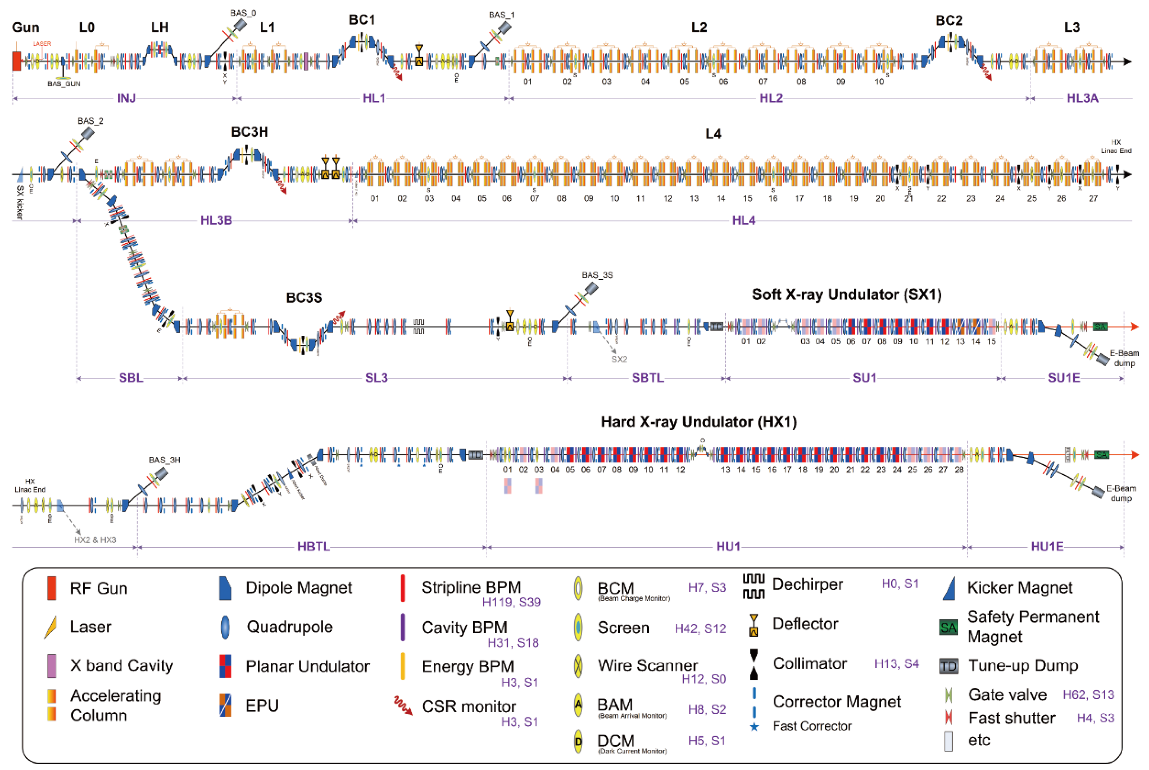
2. LINAC
The PAL-XFEL LINAC is divided into four acceleration sections (L1, L2, L3, and L4), three bunch compressors (BC1, BC2, BC3), and a dogleg transport line to the undulators, as shown in Figure 2. The L1 section consists of two RF stations, where both are comprised of one klystron and two S-band structures, while L2 has 10, L3 has four, and L4 has 27 RF stations where each station has one klystron, four accelerating structures, and one energy doubler. A laser heater to mitigate micro-bunching instability is placed right after the injector, and an X-band cavity for linearization is placed right before the BC1. The major parameters of PAL-XFEL are summarized in Table 2.
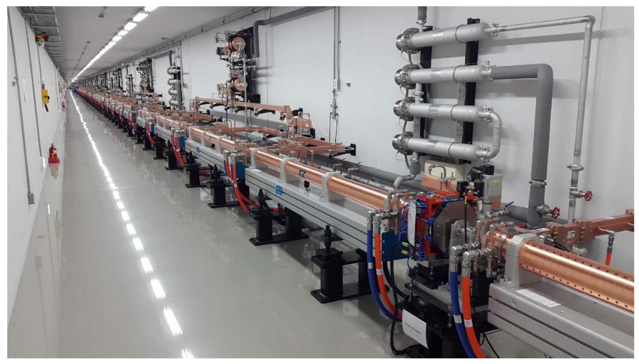
The total length of the LINAC tunnel is about 710 m. There are 176 S-band accelerating structures and 42 energy doublers. The major high power devices of the 10-GeV linear accelerator are the modulators, the klystrons, the energy doublers (ED), and the accelerating structures (AS). An energy doubler increases the peak power of the RF pulse by reducing the RF pulse length to increase the energy gain at the accelerating structure. The energy doubler was designed by PAL and fabricated by a domestic company. There are 50 modulators for the S-band klystrons, and there is one modulator for the X-band klystron that is used for linearizing the electron beam. The LINAC requires 46 S-band klystrons to obtain an electron beam energy of 10 GeV. One S-band klystron is dedicated for the RF gun, and three RF stations are designated for deflectors to measure the electron bunch length.
The klystron requires an RF drive signal at the level of a few hundred watts. A low-level radio frequency (LLRF) and a solid-state amplifier (SSA) are necessary to supply the drive signal to a klystron. To achieve beam energy stability of below 0.02% and an arrival time jitter of 20-fs for PAL-XFEL, the LINAC RF parameters should be as stable as 0.03 degrees for the RF phase and 0.02% for the RF amplitude for S-band RF systems, and 0.1 degree/0.04% for the X-band linearizer RF system. The pulse-to-pulse klystron RF stability is determined by the klystron beam voltage driven by a modulator. Therefore, the klystron modulator beam voltage should be as stable as 50 ppm for the 0.03-degree S-band RF and 0.1-degree X-band RF [3].
An LLRF system consists of an SSA, a phase and amplitude detector (PAD), and a phase and amplitude control (PAC) unit. The function of the PAC is to control the phase and amplitude of the RF drive signal to a klystron, to provide a pulsed RF signal, and to reverse the RF phase of the klystron drive signal in the middle of the pulse by turning on the Phase Shift Key (PSK) 180-degree phase shifter). The RF pulse length of the drive signal is 4 μs and the PSK is on after 3.17 μs from the starting time of the pulse. The PAL-XFEL LINAC tunnel and the klystron gallery are shown in Figure 3 and Figure 4, respectively.
3. Undulator
The PAL-XFEL undulator system consists of 20 planar undulators for the hard X-ray line (HX) and seven planar undulators for the soft X-ray undulator line (SX) [4]. The HX covers a wavelength of λ = 0.1~0.6 nm using a 4 to 10-GeV electron beam. They are all out-vacuum undulators with variable gaps. The SX covers a wavelength of λ = 1.0–4.5 nm using a 3.15-GeV electron beam. The HX undulators have a 26-mm undulator period. The gap is controlled remotely within 1 µm repeatability and the minimum gap is 8.3 mm. The height is controlled remotely, too. The SX undulators have a 35-mm undulator period and a minimum gap of 9.0 mm. Both hard and soft X-ray undulators are planar type, and have the same structures except for the magnets. A self-seeding section is prepared in HX undulator line. Two elliptically polarizing undulators are planned to be installed at the SX beamline in coming years. The installed HX undulators are shown in Figure 5.
4. Diagnostic System
For the operation of PAL-XFEL, electron beam parameters, such as beam positions, energy, charge, transverse beam size, bunch length, and arrival time, should be measured and monitored. A total of 209 beam position monitors (BPMs) are used for the electron beam position measurement [5]. Forty-nine of them are cavity type BPMs, which can measure the beam position with sub-micrometer resolution in the undulator beamline. Ten bunch charge monitors are installed for the bunch charge measurement from the gun as well as beam loss monitoring though the accelerator. The beam profile is measured with 54 screen monitors with YAG and/or Optical Transition Radiation (OTR) screens. Six spectrometer dipole systems are located at the gun section, laser heater, BC1, soft X-ray branch, BC3S and hard X-ray LINAC end. At both beam dumps at the ends of the hard and soft X-ray beamlines, the beam energy can also be measured with the screens. Three S-band deflector systems after BC1, BC3H and BC3S are used to measure the bunch longitudinal phase space. Table 3 summarizes the major components of beam diagnostics and their functions.
5. Beamlines
There is one undulator line for the HX application and another for the SX application. However, there are several end-stations for each undulator line to support various requests from users. For hard X-ray application, there are two end-stations called HEH1 for the pump-probe experiment and HEH2 for the imaging [6]. These two stations are located in tandem. In order to provide HX FEL photons to HEH2, the entire HEH1 stage is able to move in the transverse direction by 1 m. When HX/SX FEL photons emerge from their corresponding undulator system, they pass through various components located in the undulator hall (UH) and the optics hall (OH). Both halls are isolated with proper concrete shielding.
For the HX case, photons are then allowed to enter the experimental hall (EH) where HEH1 and HEH2 are located. Mirrors and a double crystal monochromator (DCM) are located in UH/OH as well as various collimators and safety shutter for radiation safety. In HEH1, beam position monitors (BPM) and profile intensity monitors (PIM) are installed to measure the position and the intensity of the HX FEL beam. An optical laser/X-ray correlator (OXC) is also installed to measure the offset of photon arrival times in fs accuracy. Two Be compound refractive lenses (Be-CRL) are installed along with three slits to define and optimize the XFEL beam. In the final stage, there is a hexapod diffractometer and 4-circle goniometer to adjust sample’s location. Finally, there is a robotic arm to control its position of the detector. The HEH1 beamline is shown in Figure 6.
HEH2 is designed based on forward scattering geometry, and will be used for the coherent X-ray imaging (CXI) or the serial femtosecond crystallography (SFX) [7]. The XFEL beam is focused to about 2 μm by the K-B mirror. A wire scanning method was used to measure the focusing beam profiles. A tungsten wire with a diameter of 200 μm was placed at the focal point. A photo diode detector placed behind the wire was also used to measure the beam intensity during the wire scanning. There are also several diagnostic devices such as Pop-in, Quadrupole BPM (QBPM), and photo-diodes. The HEH2 beamline is shown in Figure 7.
For the SX beamline, there are also two end-stations: one for coherent diffraction imaging (CDI) or X-ray emission/absorption spectroscopy (XES/XAS), and another for SX resonant scattering.
6. FEL Commissioning
After the Injector Test Facility (ITF) had stopped its operation by the end of September 2015, the photocathode RF gun and the two S-band accelerating structures at the ITF were moved to the main PAL-XFEL LINAC. The installation of 51 klystron modulators in the LINAC gallery was finished as of 30 November 2015. Twenty (20) HX undulators for the HX line were installed as of December 2015 in the 250-m long HX undulator tunnel. Since the PAL-XFEL LINAC has all new RF components, an RF aging or conditioning period is required. This RF conditioning had started in November 2015, and continued until the Korean Nuclear Safety and Security Commission (NSSC) issued the operation permission on 12 April 2016. The actual beam commissioning was started on 14 April 2016. Since the ITF parts have already been conditioned during their use from 2012 to 2015, the electron beam emitted from the photocathode gun quickly arrived at the first beam analyzing station (BAS0) on the same day. By 25 April, the 10-GeV electron beam reached BAS3, and the commissioning of the LINAC was completed [8].
Even though the 10-GeV beam is available, we have decided to reduce the electron beam energy to 4-GeV in order to send the electron beam to the main dump through the 6.7-mm gap undulator chambers. Also, the gaps of all undulators were fully opened. These two actions were intentionally chosen to minimize radiation damages to the permanent magnets of the undulator system. After the 4-GeV electron beam reached the main dump, an effort to lase the photon beam was carried out with several feedback algorithms including the beam-based alignment (BBA) technique. Finally, we lased the photons at 0.5 nm on 06:00 14 April 2016. The third harmonic spectrum of 6.6 keV was measured with a single shot spectrometer located in the HEH1, as shown in Figure 8 [9]. Its width was 30 eV or 0.45%. Figure 9 shows the snapshot of the 0.2-nm lasing. A bunch length of 12.7-fs was measured by S-band Transverse Deflecting Cavity (TCAV) with a peak current of 3.7-kA. Major achievements and unexpected interruptions during the commissioning are summarized in Table 4.
7. Summary
The PAL-XFEL project has been successfully constructed and commissioned by the end of 2016. It has now provided XFEL photons of 0.1 nm as designed. The Pohang Accelerator Laboratory has already issued a call for proposals to potential (domestic and international) users on February 6, 2017. The successful user will use PAL-XFEL’s first light in June 2017.
Acknowledgments
In Soo Ko thanks to all members of the PAL-XFEL project (2011–2016) supported by Ministry of Science, ICT and Future Planning, Korea for their endeavor and dedications.
Author Contributions
Contributions of authors are following: H.-S.K. Accelerator system design & commissioning; Hoo.H. Linac RF system design & commissioning; C.K. Diagnostics system design & commissioning; G.K. Diagnostics system design & commissioning; C.-K.M. Laser system design & commissioning; H.Y. Accelerator system design & commissioning; S.Y.B. Control system design & construction; H.-J.C. Control System design & construction; G.M. Control system design & construction; B.R.P. Machine interlock system design & construction; Y.J.S. Control system design & construction; D.C.S. Control system design & construction; J.Hu. LLRF system design & construction; J.Ho. RF-Gun design & construction; S.J. Laser System design & construction; S.-H.K. Klystron modulator system design & construction; K.K. Linac RF system design & commissioning; D.N. Vacuum system design & construction; S.S.P. Klystron modulator system design & construction; Y.J.P. Linac RF system design & construction; Y.G.J. Undulator system design & construction; S.H.J. Magnet power supply system design & construction; H.G.L. Undulator system design & construction; San.L. Undulator system design & construction; Soi.L. BPM system design & construction; B.O. Diagnostic system design & construction; H.S.S. Magnet system design & construction; J.-H.H. Injector system design and commissioning; M.H.K. Radiation safety system design and construction; N.-S.J. Radiation safety system design and construction; Y.-C.K. Building design and construction; M.-S.L. Building design and construction; B.-H.L. Utility system design and construction; C.-W.S. Utility system design and construction; I.-S.M. Building design and construction; J.-M.Y. Building design and construction; Y.W.P. Beam Dynamics; W.-W.L. Undulator system design & construction; C.-S.L. Beamline interlock system design & construction; H.S. Data center design & construction; J.H.K. Network system design & construction; Y.K. Beamline commissioning; J.H.L. Beamline commissioning; S.-Y.P. Control & DAQ system; J.K. X-ray optics commissioning; Jaeku P. Control & DAQ system; I.E. Optical laser system design, construction & commissioning; S.R. X-ray optics; Sun.K. Beamline design & commissioning; K.H.N. Serial femtosecond crystallography instrumentation design & commissioning; Jaehyun P. Serial femtosecond crystallography instrumentation design & commissioning; Jaehun P. Optical laser system commissioning; San.K. Coherent X-ray imaging instrumentation design & commissioning; Soo.K. Soft X-ray beamline design & commissioning; R.A. Soft X-ray beamline design & commissioning; S.H.P. Soft X-ray beamline design & commissioning; K.S.K. X-ray detector; Hyo.H. X-ray detector; S.N.K. Vacuum & beamline construction; Seo.K. Mechanical design & beamline construction; C.-J.Y. Beamline planning & management; B.-S.K. Beamline planning & management; T.-H.K. Beamline planning & management; K.-W.K. Beamline planning & management; S.H.K. Building design and construction; Hee-S.L. Radiation safety system design and construction; Heung.-S.L. RF system design and commissioning; K.-H.P. Magnet power supply system design & commissioning; T.-Y.K. Beamline commissioning; D.-E.K. Undulator system design & commissioning; K.B.L. Beamline commissioning.
Conflicts of Interest
The authors declare no conflict of interest.
References
- Nam, S.H.; Kang, H.S.; Ko, I.S.; Cho, M. Upgrade of Pohang Light Source (PLS-II) and Challenge to PAL-XFEL. Synchrotron Radiat. News 2013, 26, 24–31. [Google Scholar] [CrossRef]
- Ko, I.S. Status of PAL-XFEL Construction. Bull. AAPPS 2016, 26, 25–31. [Google Scholar]
- Lee, H.S.; Park, S.S.; Kim, S.H.; Park, Y.J.; Heo, H.; Heo, I.; Kim, K.H.; Kang, H.S.; Kim, K.W.; Ko, I.S.; et al. PAL-XFEL Linac RF System. In Proceedings of the 7th International Particle Accelerator Conference, Busan, Korea, 8–13 May 2016; Petit-Jean-Genaz, C., Ed.; JACOW: Geneva, Switzerland, 2016; pp. 3192–3194. [Google Scholar]
- Kim, D.E.; Jung, Y.G.; Lee, W.W.; Kang, H.S.; Ko, I.S.; Lee, H.G.; Lee, S.B.; Oh, B.G.; Suh, H.S.; Park, K.H.; et al. Development of PAL-XFEL Undulator System. In Proceedings of the 7th International Particle Accelerator Conference, Busan, Korea, 8–13 May 2016; Petit-Jean-Genaz, C., Ed.; JACOW: Geneva, Switzerland, 2016; pp. 4044–4046. [Google Scholar]
- Kim, C.; Lee, S.; Kim, G.; Oh, B.; Yang, H.; Hong, J.; Choi, H.J.; Mun, G.; Baek, S.; Shin, D.; et al. Diagnostic System of the PAL-XFEL. In Proceedings of the 7th International Particle Accelerator Conference, Busan, Korea, 8–13 May 2016; Petit-Jean-Genaz, C., Ed.; JACOW: Geneva, Switzerland, 2016; pp. 2091–2094. [Google Scholar]
- Park, J.; Eom, I.; Kang, T.-H.; Rah, S.; Nam, K.H.; Park, J.; Kim, S.; Kwon, S.; Park, S.H.; Kim, K.S.; et al. Design of a hard X-ray beamline and end-station for pump and probe experiments at Pohang Accelerator Laboratory X-ray Free Electron Laser Facility. Nucl. Instrum. Methods Phys. A 2016, 810, 74–79. [Google Scholar] [CrossRef]
- Park, J.; Kim, S.; Nam, K.-H.; Kim, B.S.; Ko, I.S. Current Status of the CXI Beamline at the PAL-XFEL. J. Korean Phys. Soc. 2016, 69, 1089–1093. [Google Scholar] [CrossRef]
- Han, J.H. Beam Commissioning of PAL-XFEL. In Proceedings of the seventh International Particle Accelerator Conference, Busan, Korea, 8–13 May 2016; Petit-Jean-Genaz, C., Ed.; JACOW: Geneva, Switzerland, 2016; pp. 6–10. [Google Scholar]
- Zhu, D.; Cammarata, M.; Feldkamp, J.M.; Fritz, D.M.; Hastings, J.B.; Lee, S.; Lemke, H.T.; Robert, A.; Turner, J.L.; Feng, Y. A single-shot transmissive spectrometer for hard X-ray free electron laser. Appl. Phys. Lett. 2012, 101, 034103. [Google Scholar] [CrossRef]
Figure 1.
Overview of Pohang Accelerator Laboratory. The Pohang Light Source (PLS) is shown in the middle (circular building) and PAL-XFEL is shown above the PLS.
Figure 1.
Overview of Pohang Accelerator Laboratory. The Pohang Light Source (PLS) is shown in the middle (circular building) and PAL-XFEL is shown above the PLS.

Figure 2.
Schematic layout of PAL-XFEL.

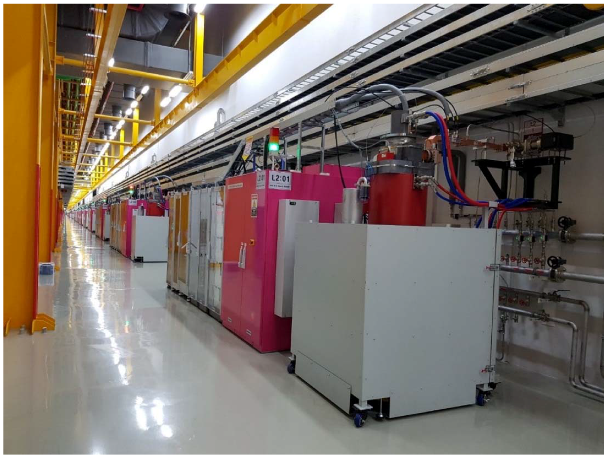
Figure 3.
LINAC tunnel of PAL-XFEL.

Figure 4.
Klystron gallery of PAL-XFEL.

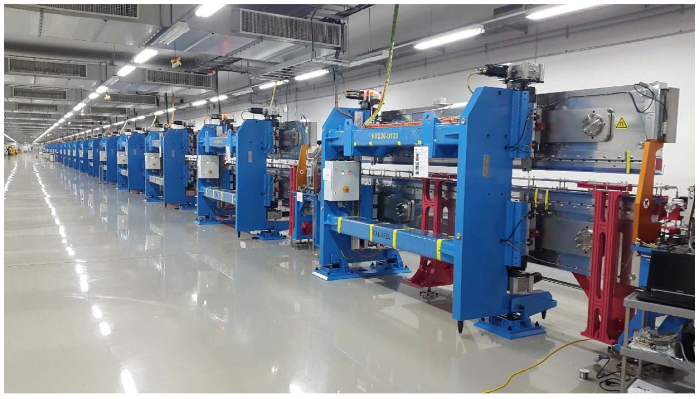
Figure 5.
Hard X-ray undulator tunnel of PAL-XFEL.

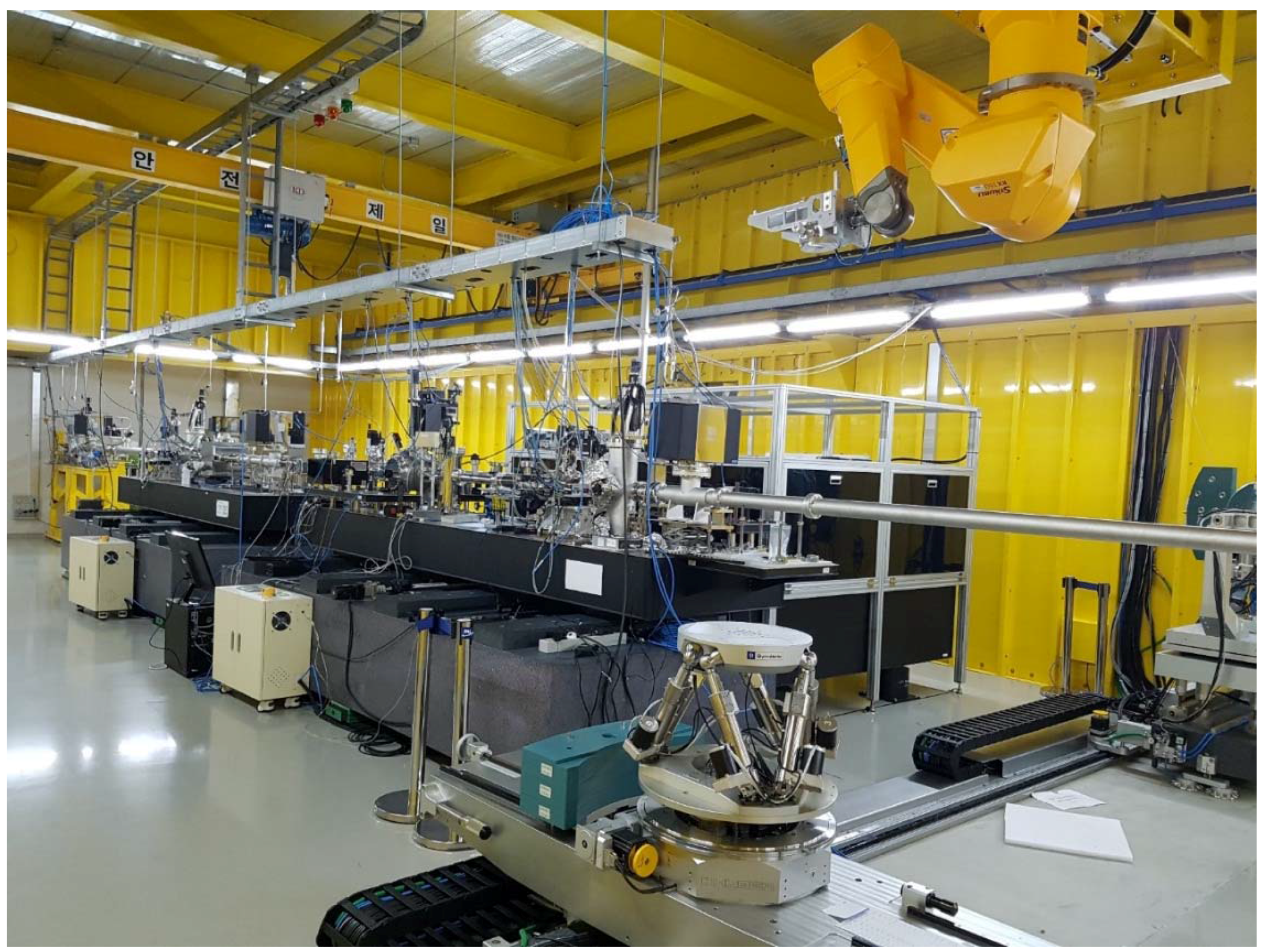
Figure 6.
Inside view of HEH1.

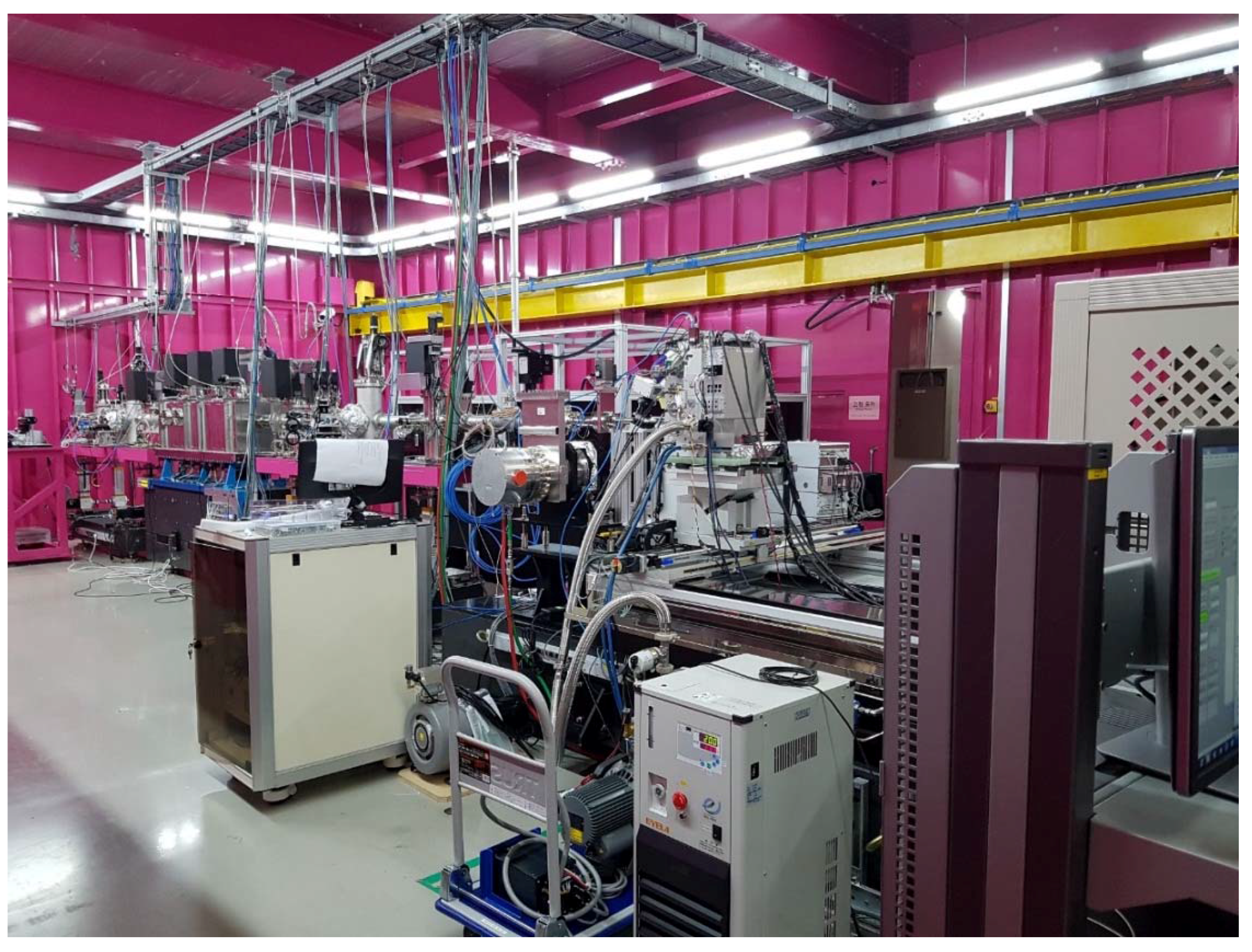
Figure 7.
Inside view of HEH2.

Figure 8.
The third harmonic spectrum of 6.6 keV was measured with a single shot spectrometer located in the HEH1.
Figure 8.
The third harmonic spectrum of 6.6 keV was measured with a single shot spectrometer located in the HEH1.
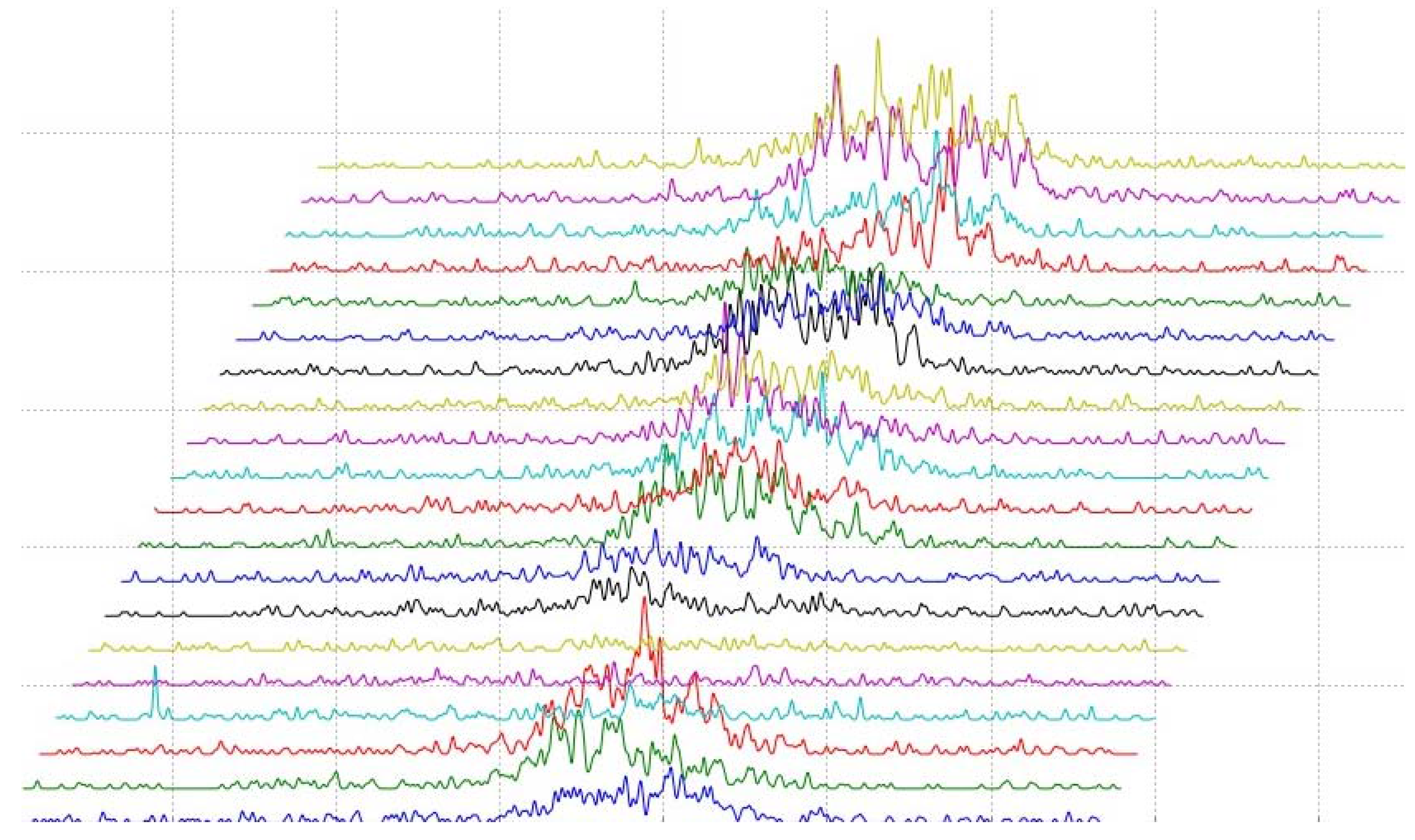
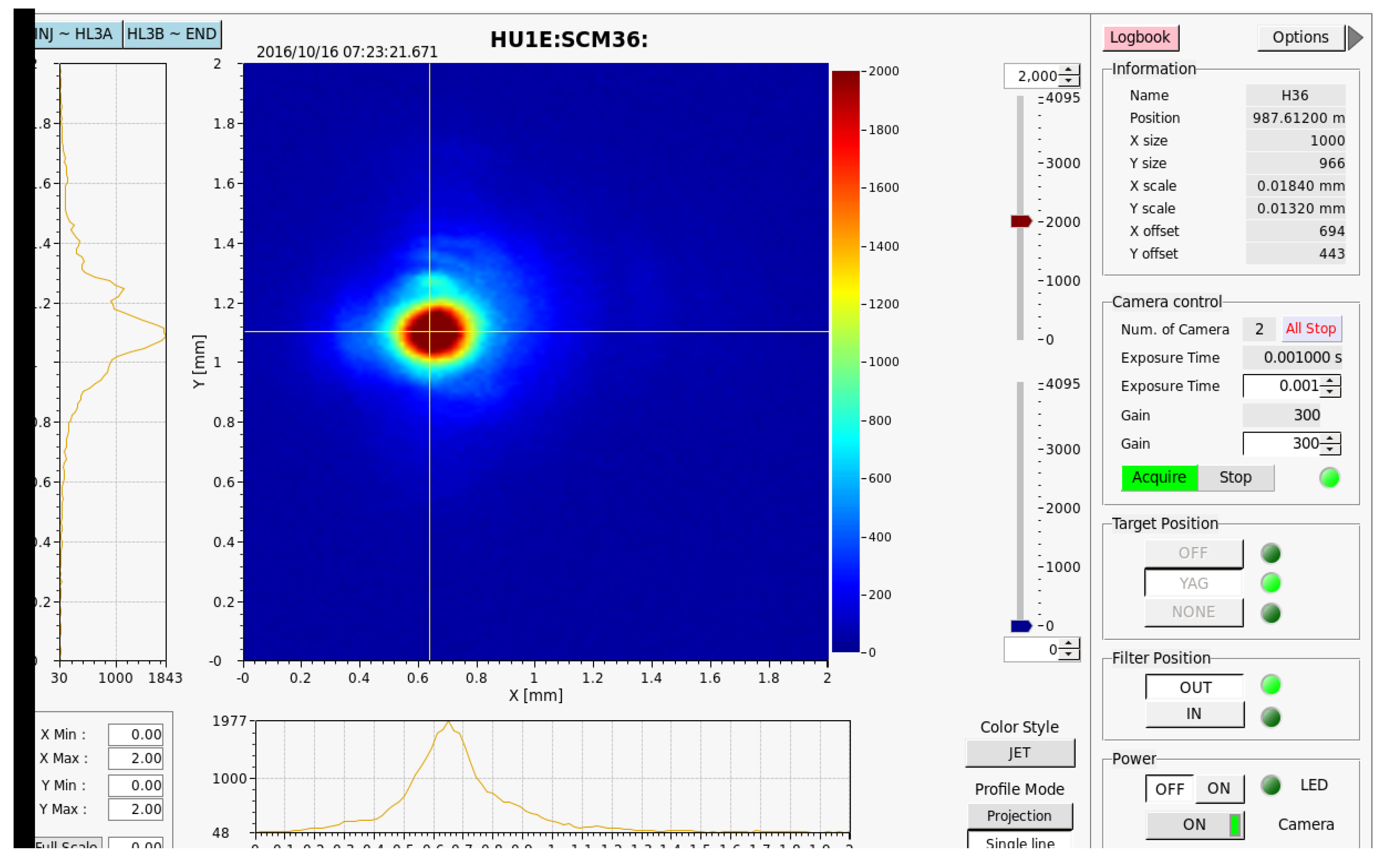
Figure 9.
Snapshot of the 0.2-nm lasing.


Table 1.
Budget of PAL-XFEL Project.
| Year | 2011 | 2012 | 2013 | 2014 | 2015 | Total |
|---|---|---|---|---|---|---|
| Budget in billion Won | 20 | 45 | 105 | 120 | 113.8 | 403.8 |
Table 2.
Major parameters of PAL-XFEL.
| LINAC | |
| FEL radiation wavelength | 0.1 nm (Hard X-ray)/1 nm (Soft X-ray) |
| Electron energy | 10 GeV |
| Slice emittance | 0.5 mm-mrad |
| Beam charge | 0.2 nC |
| Peak current at undulator | 3.0 kA |
| Pulse repetition rate | 60 Hz |
| Electron source | Photo-cathode RF-gun |
| LINAC structure | S-band normal conducting |
| Undulator | |
| Type | out-vacuum, variable gap |
| Length | 5 m |
| Undulator period | 26 mm (HX)/35 mm (SX) |
| Undulator min. Gap | 8.3 mm (HX)/9.0 mm (SX) |
| K value | 1.9727 (HX)/3.3209 (SX) |
| Peak B (in Tesla) | 0.8124 (HX)/1.0159 (SX) |
| Vacuum chamber dimension | 13.4 × 6.7 mm2 |
Table 3.
Major components of beam diagnostics and their functions.
| Parameter | Instruments | Number |
|---|---|---|
| Position Beam Energy | Stripline Beam Position Monitor | 160 |
| Cavity BPM | 49 | |
| Beam Charge | Turbo Integrated Current Transformer (ICT) | 10 |
| Beam Size | Screen Monitor | 54 |
| Wire Scanner | 9 | |
| Bunch Length | Coherent Radiation Monitor | 4 |
| Transverse Cavity | 3 | |
| Arrival Time | Arrival Time Monitor | 10 |
| Beam Loss | Beam Loss Monitor | 26 |
Table 4.
Major achievements during the commissioning.
| Date | Energy (GeV) | Remarks |
|---|---|---|
| 4/12 (2016) | Permission issued by National Nuclear Safety and Security Commission (NSSC) | |
| 4/14 | 0.152 | E-Gun and BAS0 |
| 4/18 | 0.355 | BAS1 |
| 4/19 | 0.355 | Before BC2 (No acceleration by L2) |
| 4/20 | 2.545 | BAS2 |
| 4/21 | 3.15 | BAS3 (No acceleration after BAS2) |
| 04/25 (5:30 p.m.) | 10 | BAS3 |
| 5/19 | 10 | Tuneup dump |
| 6/2 | 10 | Passing the HX undulator line, beam at the main dump |
| 06/14 (6:00 a.m.) | 4 | First lasing (0.5-nm) observed at SCM36 |
| 06/21 (3:00 a.m.) | 4 | Photon beam at Digital Current Monitor (DCM) in Optical Hutch |
| July~August | – | Summer maintenance |
| 8/16 | 4 | Commissioning resumed |
| 8/30 | 4 | Recovered 0.5-nm lasing |
| 9/9 | 4 | HX Beamline commissioning started |
| 09/12 (8:30 p.m.) | 4 | Earthquake stopped commissioning |
| 9/29 | – | Dedication ceremony |
| 10/3 | 4 | Commissioning resumed |
| 10/8 | 5.2 | 0.35-nm lasing |
| 10/16 | 6.7 | 0.2-nm lasing |
| 11/27 | 8.04 | 0.144-nm lasing and saturation |
| 12/2 | 8.04 | First experiments |
| 2/1 (2017) | 3 | 1.5-nm SX lasing and saturation |
| 3/16 | 9.78 | 0.1-nm HX lasing |
© 2017 by the authors. Licensee MDPI, Basel, Switzerland. This article is an open access article distributed under the terms and conditions of the Creative Commons Attribution (CC BY) license (http://creativecommons.org/licenses/by/4.0/).
Share and Cite
MDPI and ACS Style
Ko, I.S.; Kang, H.-S.; Heo, H.; Kim, C.; Kim, G.; Min, C.-K.; Yang, H.; Baek, S.Y.; Choi, H.-J.; Mun, G.; et al. Construction and Commissioning of PAL-XFEL Facility. Appl. Sci. 2017, 7, 479. https://doi.org/10.3390/app7050479
AMA Style
Ko IS, Kang H-S, Heo H, Kim C, Kim G, Min C-K, Yang H, Baek SY, Choi H-J, Mun G, et al. Construction and Commissioning of PAL-XFEL Facility. Applied Sciences. 2017; 7(5):479. https://doi.org/10.3390/app7050479
Chicago/Turabian StyleKo, In Soo, Heung-Sik Kang, Hoon Heo, Changbum Kim, Gyujin Kim, Chang-Ki Min, Haeryong Yang, Soung Youl Baek, Hyo-Jin Choi, Geonyeong Mun, and et al. 2017. "Construction and Commissioning of PAL-XFEL Facility" Applied Sciences 7, no. 5: 479. https://doi.org/10.3390/app7050479
Note that from the first issue of 2016, this journal uses article numbers instead of page numbers. See further details here.