
Swirling Gas Jet-Assisted Laser Trepanning for a Galvanometer-Scanned CO2 Laser
by
 ,
,
Chao-Ching Ho
1,* ,
,
Ke-Ying Shen
2, 
Chang-Sheng Chen
1,
Yuan-Jen Chang
2,
Jin-Chen Hsu
2 and
Chia-Lung Kuo
2 1
Graduate Institute of Manufacturing Technology and Department of Mechanical Engineering, National Taipei University of Technology, Taipei 10608, Taiwan
2
Department of Mechanical Engineering, National Yunlin University of Science and Technology, Douliou, Yunlin 64002, Taiwan
*
Author to whom correspondence should be addressed.
Appl. Sci. 2017, 7(5), 502; https://doi.org/10.3390/app7050502
Submission received: 24 March 2017
/
Revised: 30 April 2017
/
Accepted: 6 May 2017
/
Published: 17 May 2017
(This article belongs to the Special Issue Selected Papers from the 2016 International Conference on Inventions)
Abstract
:Laser-drilled hole arrays are part of an important field that aim to improve efficiency without affecting the quality of laser-drilled holes. In this paper, a swirling gas jet was implemented to assist with laser trepanning for a galvanometer scanned CO2 laser. The proposed swirling gas jet is based on laser trepanning. This swirling gas jet nozzle was composed of four inlet tubes to produce the flow of the vortex. Then, the plume particles were excluded, and spatter on the surface of the workpiece decreased. Thus, this approach can mitigate the problem of overcooling. This study manipulated the appropriate parameter settings, which were simulated by computational fluid dynamics software ANSYS CFX. The proposed swirling gas jet can be used with galvanometer-based scanner systems to keep the laser beam from interference by spatter. In addition, a hollow position of the vortex was achieved by using the four inlet tubes, which resulted in pressure asymmetry in the nozzle and velocity distribution on the surface of the workpiece. The experiment verified that the depth of processing could be enhanced by 110% when trepanning at a scanning speed of 30 mm/s, and that the removal of volume could be enhanced by 71% in trepanning at a diameter of 1 mm by using a swirl assistant compared with a non-assisted condition. Furthermore, the material removal rate of the swirling jet increases when the machining area of the galvanometer-based scanner is larger.
1. Introduction
Laser-drilled hole arrays are an important concept that aim to improve efficiency without affecting the quality of laser-drilled holes. To achieve high-throughput laser processing, a gas jet is usually employed in conjunction with the laser beam to increase the material removal rate [1]. In addition, to increase the machining speed, the laser apparatus is combined with a galvanometer beam steering system to provide machining along the material on the x-y axis. A galvanometer scanner was used for high-speed steering, which allows a laser beam to be projected onto the material with fast and precise positioning [2]. In [3], a galvanometer scanner was used for the high-speed drilling of stainless steel and silicon. A combination of galvanometer-controlled scanning mirrors can be used for the cutting, drilling, and scribing of materials [4], and leads to higher throughputs for laser micromachining [5]. However, it is a challenge to perform field laser drilling with the aid of assisted gas and a galvanometer together.
During laser-drilled micromachining, the recoil-pressure forced flow of molten material moving along the sidewall of the inlet hole results in a melt ejection phenomenon [6]. The melt ejection material during the drilling process consequently resolidifies on the material exterior around the hole periphery. Nevertheless, laser-drilled holes are inherently correlated with spatter deposition owing to the solidification of rapidly ejected bulk melt material [7]. A significant amount of research has been conducted to develop an efficient gas jet-assisted spatter-ejection nozzle that can be applied to laser drilling. A straight jet is commonly used to assist the laser drilling.
Assisted gas helps to expel the molten material, reduce the spatter on the top surface of drilled holes [8], and prevent the optical window from being contaminated by the ejected droplets [9]. However, the straight jet blows air directly onto the surface of the object. This leads to excess cooling and enlarges the diameter of the holes, thereby affecting the quality of the holes [10,11]. Furthermore, the straight gas has a decelerating effect on the ejected droplets [12]. The molten slag and laser-induced plume inside the machining hole carried by the rebounding assisted gas flows may obstruct the laser processing beam and thus decrease the processing efficiency [13,14].
A swirling flow nozzle is able to generate a vacuum region in the central region of the swirling flow [15]. The flow stream removes a great amount of heat and plasma plume to decrease the influences of thermal effects and vaporization-induced recoil pressure during laser cutting [16] and ablation [17]. By implementing a swirling flow during the laser ablation, the laser-induced plume can be removed efficiently, and the surface roughness can be significantly reduced [18]. Our previous work [9] showed that the swirling gas jet nozzle had the best efficiency under pulsed laser drilling, but it is limited to single-hole drilling.
To the best of our knowledge, the combination of a galvanometer beam steering system and an assisted swirling gas jet on laser trepanning has not been investigated previously. The effects of the swirling flow on laser trepanning are not known. In general, there are three methods for laser drilling: single-pulse drilling, percussion drilling, and trepanning. Laser trepanning is examined in the current study [19]. This study is aimed to design a swirling gas jet nozzle to assist laser trepanning for a galvanometer-scanned CO2 laser. This study uses computational fluid dynamics (CFD) software to simulate the swirl jet flow inside the nozzle and to examine the laser trepanning efficiency assisted by the swirling flow. Additional analysis of the flow velocity and pressure distribution of the assisted gas was undertaken to further explore the influence of gas flow.
2. Model of the Computation Domain by the Assisted Gas Jets
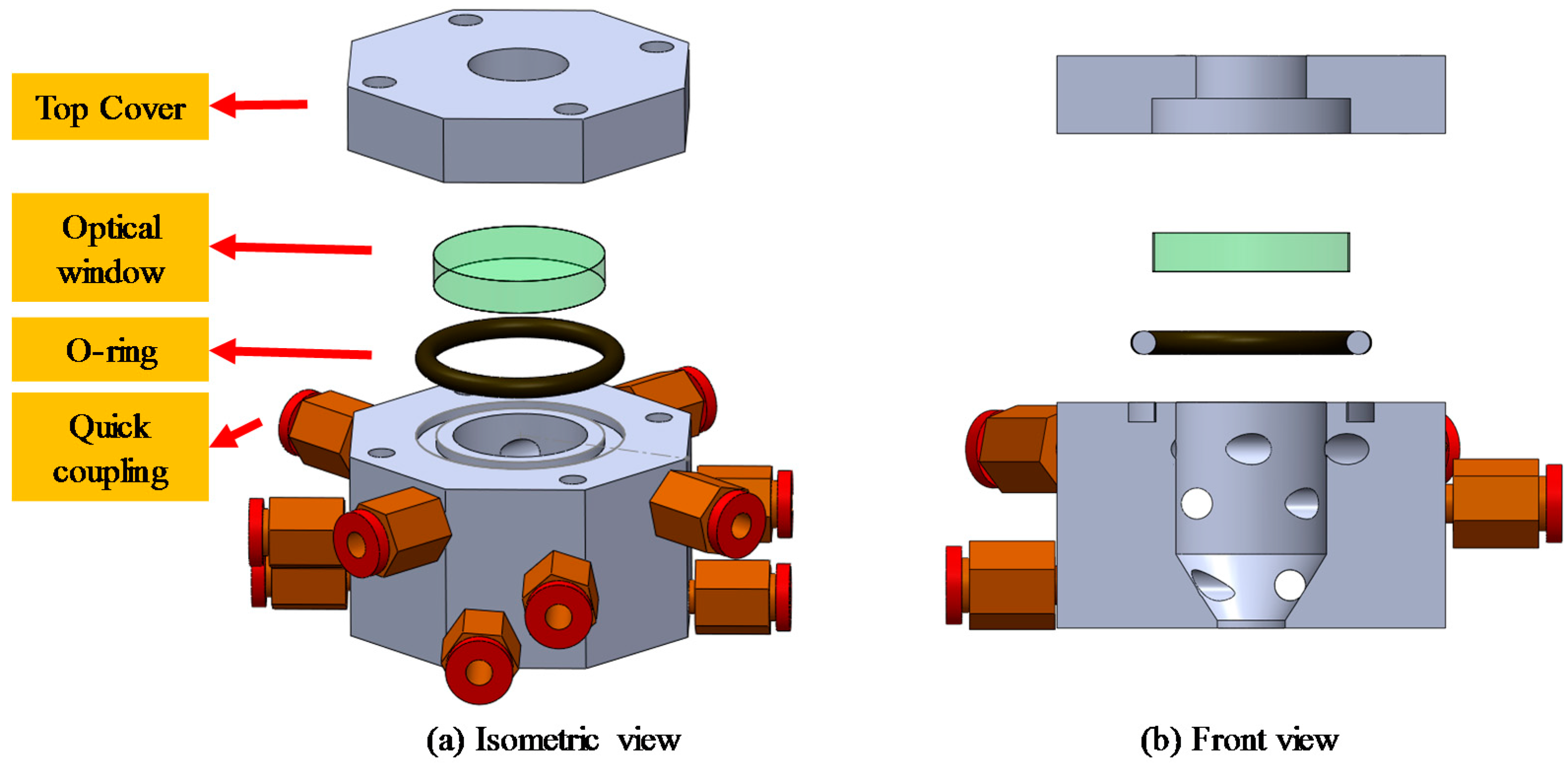
The overall structure of the proposed nozzle to produce the swirling gas jet is shown in Figure 1. The nozzle chamber consists of a top cover, optical window, main body with four gas inlet joints and eight outlet joints. The pressurized air gas is delivered via an inlet with a diameter of 5 mm into the gas chamber of the main body. The gas chamber is a cylindrical space with a flat-top inlet and tapered-tip outlet, as illustrated in Figure 1b. The nozzle is screwed into the top cover.
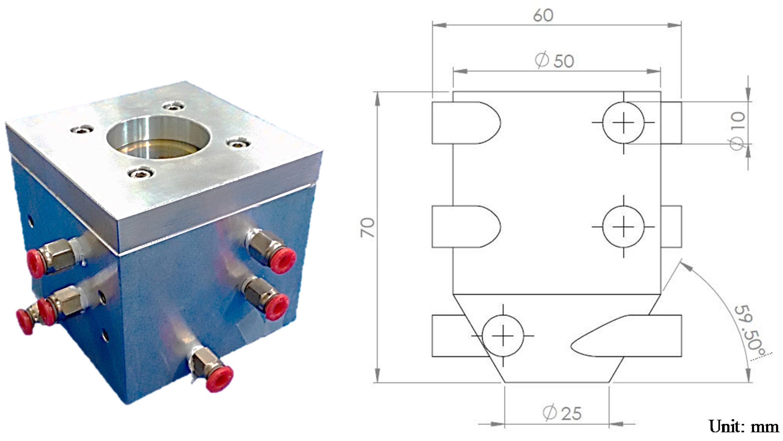
As depicted in Figure 2, the nozzle chamber is made of aluminum (60 mm × 60 mm × 70 mm) and is equipped with four gas inlets P1 and eight gas outlets P2 for gas flow. The standoff distance between the nozzle and the material (i.e., the distance from the nozzle exit to the workpiece surface) was set to 10 mm in the simulation and the experiments. Figure 3 shows a photograph and dimensions of the physical model of the swirling gas jet for galvanometer-scanned CO2 laser drilling.
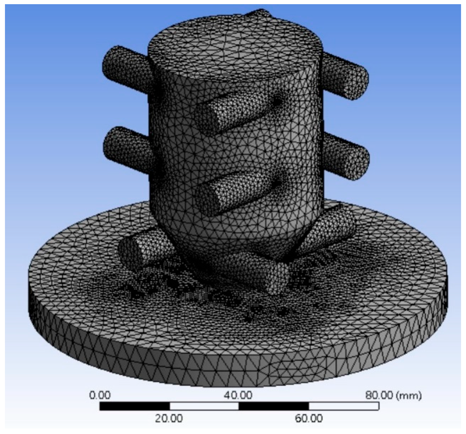
A three-dimensional (3D) model for the computation domain of the gas jets was constructed using the ANSYS CFX software (ANSYS, Inc., Canonsburg, PA, USA). In this work, a steady-state incompressible flow was treated, the flow of a gas through the nozzles was assumed to be viscous, and a k-ε turbulence model was used.
The transport equations for the RNG k-ε turbulence mode are expressed as follows [20]:
where k is the turbulent kinetic energy; ε is the turbulent dissipation rate; μeff is the effective viscosity; C1ε, C2ε, and C3ε are empirical constants; and αk and αε are the inverse effective Prandtl numbers for k and ε, respectively. GK represents the generation of turbulent kinetic energy produced by the mean velocity gradients. GB is the generation of turbulence kinetic energy produced by buoyancy, and YM is the contribution of the fluctuating dilatation in compressible turbulence to the overall dissipation rate.
As depicted in Figure 4, the isometric view for the mesh structure was drawn in the preprocessor. The simulation geometry consisted of a laser-drilled surface. Simulation parameters are listed in Table 1. A convergence analysis was performed with a 1% convergent criteria setup for the flow speed calculation, which results in 43,791 elements that were used in the simulation model. The thermal interactions of the assisting gas with the workpiece material are not considered. In the numerical analysis, the converged results were obtained for P1 = 300 kPa and P2 = 30 kPa.
3. Numerical Results
Numerical results for the velocity contours and velocity profiles of the top-section view at 2 mm above the surface of the machining material are depicted in Figure 5. As exhibited in Figure 5a, the numerical results show spatter flow through the swirling gas jet nozzle, and hence the gas outflow is obtained. The swirling gas jet can carry the plume particles, rotate the particles cyclonically upward inside the nozzle from the nozzle inlet, and then extract particles from the tube at the top of the nozzle. As exhibited in Figure 5b, velocity profile is perceived as a hollow interior space generated in the central region of the swirling flow, which can keep the laser beam from contamination by ejected spatter. Hence, the plume particles produced above the laser trepanning inlet hole were expelled by the swirling flow more efficiently.
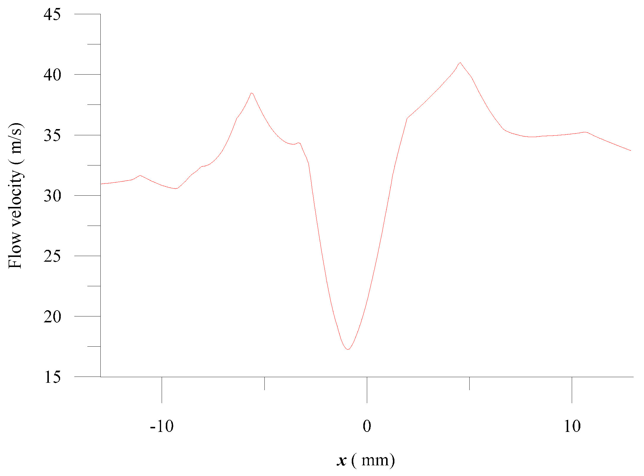
By using the techniques of image processing and analyzing CCD (charge coupled device) recorded images of the plasma [21], it is observed that the average height of a plasma plume generated during laser processing was approximately 2 mm. Therefore, the position for the top-section view of the nozzle was placed at 2 mm above the surface of the machining material to investigate the influence of gas flow on plume particles. According to the velocity profile of the swirling flow from the top-section view of the nozzle, the gas velocity is much higher in the circulation zone and is centralized. A corresponding finite-element simulated flow velocity is present in the x direction with a movement of ±12.5 mm from the center of the nozzle at 2 mm above the surface of the machining material, as represented in Figure 6. It is observed that a low-speed region (i.e., 17 m/s) appeared at the nozzle center, and that the spatter was drawn out through the gas outlet as the flow speed increased radially outward from the central region to a peak value of 40 m/s, and then declined to around 30 m/s.
Plots of the pressure distribution along the nozzle were simulated, and the pressure profiles of the swirling gas jet at 2 mm above the workpiece surface are observed in Figure 7. According to the pressure profile of the swirling flow from the top-section view of the nozzle, the gas pressure is reduced inwardly from the outer rim to the central zone. The corresponding finite-element-simulated pressure distribution is present along the x direction with a movement of ±12.5 mm from the center of the nozzle at 2 mm above the surface of machining material, as shown in Figure 8.
It was observed that a low-pressure region (i.e., −2.4 kPa) appeared at the nozzle center, and the spatter was sucked up through the gas outlet as pressure increased radially outward from the central region to a peak value of 0 kPa, which was sustained. Pressure distribution was found to be in good agreement with the velocity profiles generated by the swirling nozzle. By comparing this with the simulation results obtained for the previous swirling gas jet nozzle, it was found in the literature [18] and in our previous work [9] that the ejected plume may circulate back from the outward of the impinging jet to the bottom of the workpiece. Thus, spatter accumulated around the hole periphery. Therefore, the proposed swirling nozzle outperforms the previous implementations in terms of generating a thorough swirling lifted flow. Moreover, the thorough swirling lifted flow collected the ejected particles and melted debris that flowed toward the edge together, thus decreasing the height of the spatter.
4. Experiment
4.1. Gas Flow Visualization
As displayed in Figure 9, the trajectory motion of plume particles under a thorough swirling lifted flow was visualized experimentally by the digital camera (Canon IXUS 210, Canon Inc., Tokyo, Japan) to verify the simulation. Flour powder mixed with water was prepared as a substitute for the simulated plume particles. As exhibited in Figure 9b, it was found that the vacuum effect of the upward stream produced by the swirling flow nozzle caused the flour powders to ascend from the water surface. (The flow visualization for the flour powders under the lifting force by the swirling gas jet nozzle with suction is available as supplementary data.) The gas flow visualization is found to be in good agreement with the numerical results.
4.2. Laser Trepanning Depth Comparison
A CO2 laser was employed with a specific swirling flow nozzle in laser trepanning (Table 2), and the depth and the machining rate of the laser trepanning hole were inspected experimentally. As illustrated in Figure 10, the system was set on a high-precision XY stage, and a Miniscan II-10 scanner from Raylase (Wessling, Germany) was used for this work. The material under investigation was an acrylic workpiece (300 mm × 300 mm, 10 mm thick). In the experiments, the laser beam was focused at the material surface, thus providing a beam spot for trepanning. The laser source was a CO2 laser (Series 48, Model 48-1, Synrad, Mukilteo, WA, USA) that provided a Gaussian laser beam. The output maximum beam diameter was 6.6 mm, and the beam divergence was typically below 4 mrad. A lens with a focal length of 170 mm was used to focus the laser beam, and the effective spot diameter was 400 μm.
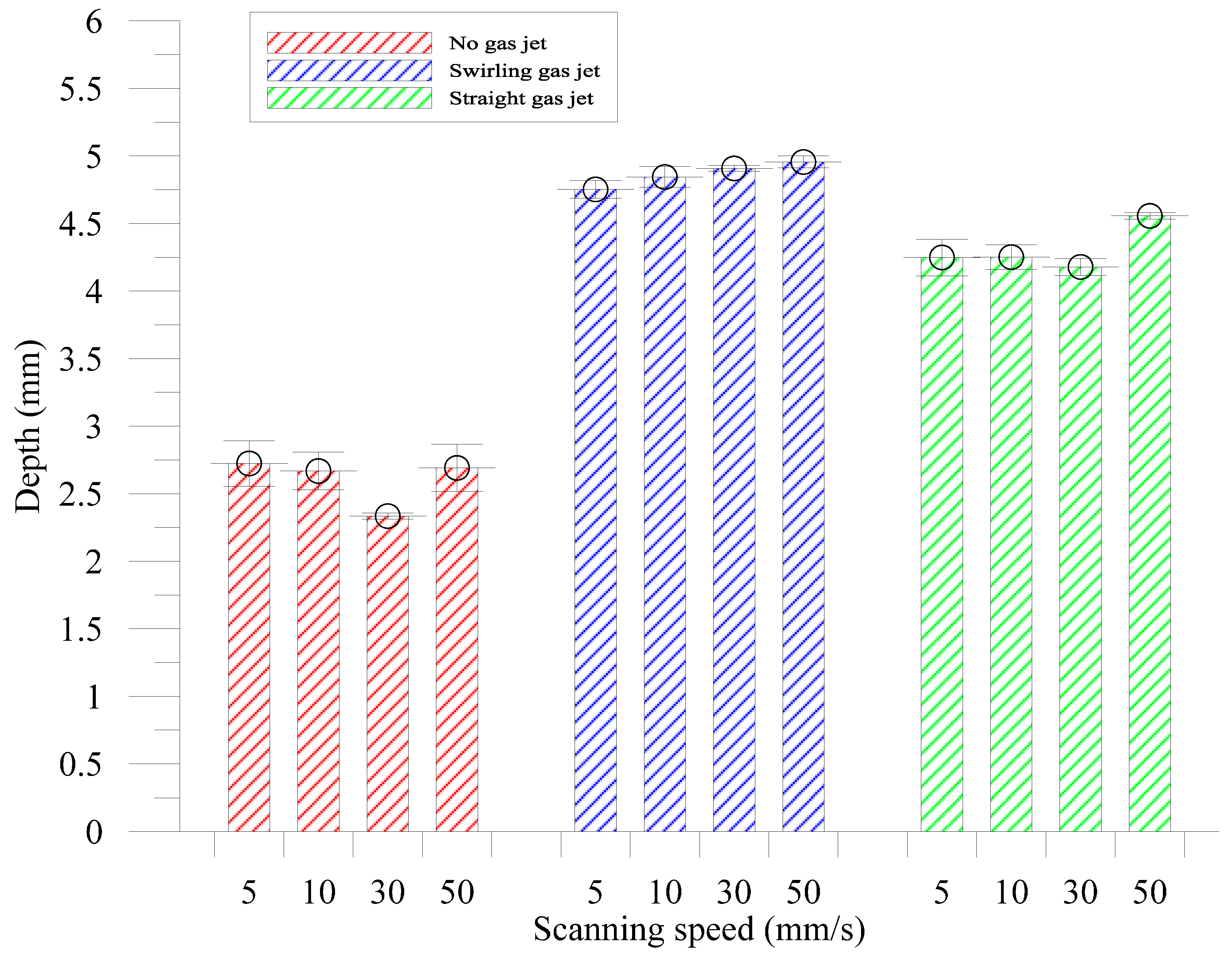
Laser trepanning involves steering a laser beam to scan in a circumferential-closed trajectory over the workpiece surface to create the perimeter of a hole [22,23]. To compare the trepanning depth performances between the different nozzle configurations, three possible nozzle configurations were explored and investigated in the present experiments: a configuration without an assisted nozzle (no gas jet), swirling gas jet, and conventional straight gas jet. The trepanning depth comparison tests were performed with laser trepanning using different gas jet configurations on the workpiece surface for four different values of scanning speed settings, i.e., 5, 10, 30, and 50 mm/s. Trepanning holes were produced by drilling a series of overlapping circles around the perimeter of a ring. The trepanning durations were fixed at 0.272 s.
In Figure 11, a superior trepanning depth obtained by a swirling gas jet is observed. The profile image was measured for different gas jet configurations, as shown in Figure 12. The experiment verified that the average depth of trepanning could be enhanced by 88% by using the swirl assistant compared with the non-assistant condition, and outperformed a straight gas jet condition by 13%. Furthermore, the depth of processing in trepanning at a scanning speed of 30 mm/s could be enhanced by 110% by using the swirl assistant compared with the non-assistant condition, and improved by 79% by using the swirl assistant compared with the non-assistant condition.
It is shown that the swirling gas jet nozzle had the best trepanning depth among the configurations. However, the swirling gas jet nozzle has a disadvantage that reduced the scan field. Hence, the workpiece was moved with the XY table to stitch an adjacent pattern to form a large-area pattern.
4.3. Laser Trepanning Volume Comparison
Laser trepanning was carried out by a galvanometric scanning system to investigate the material removal rate with different gas jet configurations at a laser scanning speed of 5 mm/s. The formation of trepanning through a hole with different trepanning diameters in a 24-mm-thick acrylic workpiece by a CO2 laser was investigated at a trepanning time of 1.109 s. It was found that as the trepanning diameter increased, the material removal volume by trepanning increased rapidly, as illustrated in Figure 13.
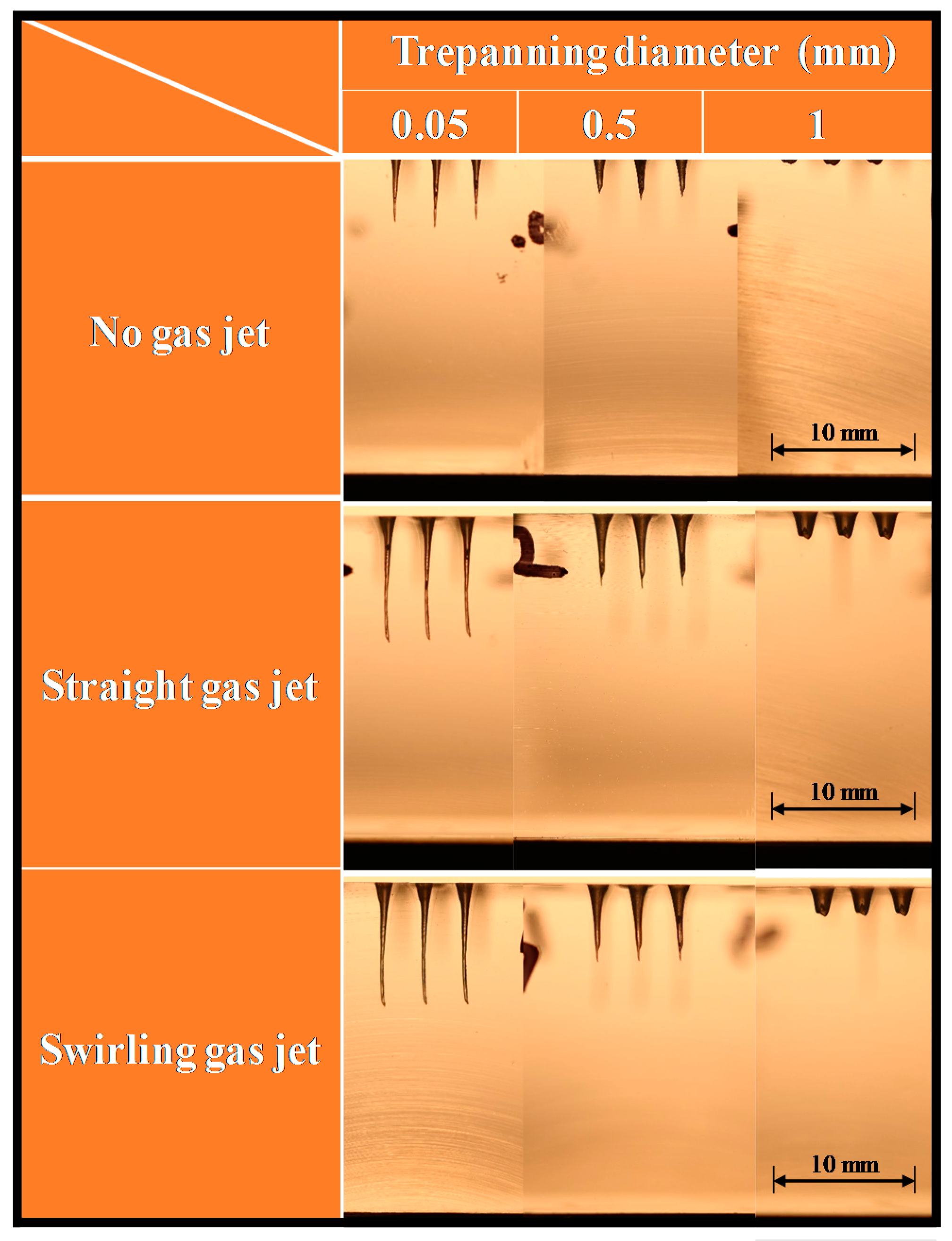
A profile image was measured for different gas jet configurations, as shown in Figure 14. The experiment verified that the average volume of trepanning could be enhanced by 71% when using the swirl assistant compared with the non-assistant condition, and outperformed by 11% compared with a straight gas jet condition at a trepanning diameter of 1 mm. It is revealed that the swirling gas jet nozzle had the best trepanning volume among the assisted gas jet configurations.
5. Conclusions
The combination of swirling gas jet nozzles and galvanometer-based laser micromachining has been successful for laser trepanning with a 10.6-μm-wavelength CO2 laser. Three different gas jet configurations were investigated in the present study to understand the effects of assisting gas on the trepanning efficiency for an acrylic sheet. The simulation results showed that the proposed swirling gas jet could produce hollow interior space generated by the swirling flow to keep the laser beam from being contaminated by the ejected plume particles, and to create a cyclonical effect of the upward flow to effectively remove spatter. Experiments were carried out to study the performance of the swirling gas jet, and the results matched the simulations. Furthermore, the validity of the experimental results was further examined for the galvanometer-based laser trepanning processes. It was found that under certain operating conditions (i.e., inlet pressure of 300 kPa and outlet pressure of 30 kPa), the swirling gas jet nozzle had the best trepanning efficiency among the assisted gas jet configurations. The proposed swirling gas jet nozzle can be applied to industrial applications to produce a dense pattern of hole arrays.
Supplementary Files
Supplementary File 1Acknowledgments
The work was supported by the Ministry of Science and Technology, Taiwan. MOST 105-2221-E-027-137 and 105-2622-E-027-020-CC3.
Author Contributions
Chao-Ching Ho made substantial contributions to the conception and design, analysis and interpretation of data, and wrote the paper; Ke-Ying Shen performed the experiments; Chang-Sheng Chen performed the simulations; Jin-Chen Hsu, Yuan-Jen Chang, and Chia-Lung Kuo discussed the results and implications and commented on the manuscript at all stages.
Conflicts of Interest
The authors declare no conflict of interest.
References
- Sezer, H.; Li, L.; Leigh, S. Twin gas jet-assisted laser drilling through thermal barrier-coated nickel alloy substrates. Int. J. Mach. Tools Manuf. 2009, 49, 1126–1135. [Google Scholar] [CrossRef]
- Ho, C.-C.; Liang, Y.-S. Research and development of high-speed laser scanning galvanometer system. Smart Sci. 2013, 1, 82–85. [Google Scholar] [CrossRef]
- Karnakis, D.; Rutterford, G.; Knowles, M. High power DPSS laser micro-machining of stainless steel and silicon for device singulation. Pulse 2007, 1000, 3. [Google Scholar]
- Mishra, S.; Yadava, V. Laser beam micromachining (LBMM)—A review. Opt. Lasers Eng. 2015, 73, 89–122. [Google Scholar] [CrossRef]
- Meng, F.; Wang, H. CAD/CAM software framework design for the laser micromachining device driven by two stages. In Proceedings of the 2010 11th International Conference on Electronic Packaging Technology & High Density Packaging (ICEPT-HDP), Xi’an, China, 16–19 August 2010; pp. 902–905. [Google Scholar]
- Chak, S.K. Electrochemical discharge machining-discharge generation: A review. J. Mater. Sci. Mech. Eng. 2015, 2, 49–53. [Google Scholar]
- Kacar, E.; Mutlu, M.; Akman, E.; Demir, A.; Candan, L.; Canel, T.; Gunay, V.; Sınmazcelik, T. Characterization of the drilling alumina ceramic using Nd: YAG pulsed laser. J. Mater. Process. Technol. 2009, 209, 2008–2014. [Google Scholar] [CrossRef]
- Biffi, C.; Previtali, B. Spatter reduction in nanosecond fibre laser drilling using an innovative nozzle. Int. J. Adv. Manuf. Technol. 2013, 66, 1231–1245. [Google Scholar] [CrossRef]
- Ho, C.-C.; Chen, Y.-M.; Hsu, J.-C.; Chang, Y.-J.; Kuo, C.-L. Characteristics of the effect of swirling gas jet assisted laser percussion drilling based on machine vision. J. Laser Appl. 2015, 27, 042001. [Google Scholar] [CrossRef]
- Hsu, J.-C.; Liao, C.-Y.; Ho, C.-C.; Chang, Y.-J.; Kuo, C.L. Experiment on intermittent gas jet assisted modulated fiber laser drilling. In Applied Mechanics and Materials; Trans Tech Publication Ltd.: Zurich, Switzerland, 2014; pp. 91–95. [Google Scholar]
- Hsu, J.-C.; Lin, W.-Y.; Chang, Y.-J.; Ho, C.-C.; Kuo, C.-L. Continuous-wave laser drilling assisted by intermittent gas jets. Int. J. Adv. Manuf. Technol. 2015, 79, 449–459. [Google Scholar] [CrossRef]
- Rodden, W.; Kudesia, S.; Hand, D.; Jones, J. Use of “assist” gas in the laser drilling of titanium. J. Laser Appl. 2001, 13, 204–208. [Google Scholar] [CrossRef]
- Low, D.; Li, L.; Corfe, A. Effects of assist gas on the physical characteristics of spatter during laser percussion drilling of NIMONIC 263 alloy. Appl. Surf. Sci. 2000, 154, 689–695. [Google Scholar] [CrossRef]
- Khan, A.; Celotto, S.; Tunna, L.; O’Neill, W.; Sutcliffe, C. Influence of microsupersonic gas jets on nanosecond laser percussion drilling. Opt. Lasers Eng. 2007, 45, 709–718. [Google Scholar] [CrossRef]
- Xiahui, T.; Haihong, Z.; Guofu, Z.; Shiming, L.; Zaiguang, L. Study on aerodynamic nozzle specialized for laser welding. Laser Technol. 2000, 2, 9. [Google Scholar]
- Lei, H.; Yi, Z. Technological study of laser cutting silicon steel controlled by rotating gas flow. Opt. Laser Technol. 2009, 41, 328–333. [Google Scholar] [CrossRef]
- Boutinguiza, M.; Pou, J.; Lusquinos, F.; Quintero, F.; Soto, R.; Perez-Amor, M.; Watkins, K.; Steen, W. CO2 laser cutting of slate. Opt. Lasers Eng. 2002, 37, 15–25. [Google Scholar] [CrossRef]
- Tsai, D.-Y.; Lin, J. Characteristics of the plume particles removed by a swirling flow nozzle in laser ablation. Opt. Laser Technol. 2007, 39, 219–224. [Google Scholar] [CrossRef]
- Dahotre, N.B.; Harimkar, S.P. Laser Fabrication and Machining of Materials; Springer: Berlin/Heidelberg, Germany, 2008; Volume 51. [Google Scholar]
- ANSYS, Inc. ANSYS Fluent Theory Guide; ANSYS, Inc.: Canonsburg, PA, USA, 2013. [Google Scholar]
- Ho, C.-C.; Luo, Y.-H.; Chang, Y.-J.; Hsu, J.-C.; Kuo, C.-L. Mask assisted laser percussion drilling. J. Laser Micro Nanoeng. 2016, 11, 41–45. [Google Scholar] [CrossRef]
- Beck, T.; Bostanjoglo, G.; Kugler, N.; Richter, K.; Weber, H. Laser beam drilling applications in novel materials for the aircraft industry. Proceedings Laser Materials Processing Conference, San Diego, CA, USA, 17–20 November 1997; Laser Institute of America: Orlando, FL, USA, 1997. [Google Scholar]
- Zeng, D.; Latham, W.; Kar, A. Temperature distributions due to annular laser beam heating. J. Laser Appl. 2005, 17, 256–262. [Google Scholar] [CrossRef]
Figure 1.
Assembly of swirling gas jet nozzle unit for field laser machining. (a) Isometric view; (b) front view.
Figure 1.
Assembly of swirling gas jet nozzle unit for field laser machining. (a) Isometric view; (b) front view.

Figure 2.
Design of swirling gas jet nozzle with eight outlet tubes and four direction inlet tubes.

Figure 3.
Photograph and dimensions of physical model of swirling gas jet for field laser machining.
Figure 3.
Photograph and dimensions of physical model of swirling gas jet for field laser machining.

Figure 4.
Three-dimensional geometry and mesh designed for numerical simulation.

Figure 5.
Numerical results of (a) velocity contours (section view) and (b) velocity profile (top section view of nozzle at 2 mm above surface of machining material) for gas inlet pressure of 300 kPa and gas outlet pressure of 30 kPa.
Figure 5.
Numerical results of (a) velocity contours (section view) and (b) velocity profile (top section view of nozzle at 2 mm above surface of machining material) for gas inlet pressure of 300 kPa and gas outlet pressure of 30 kPa.
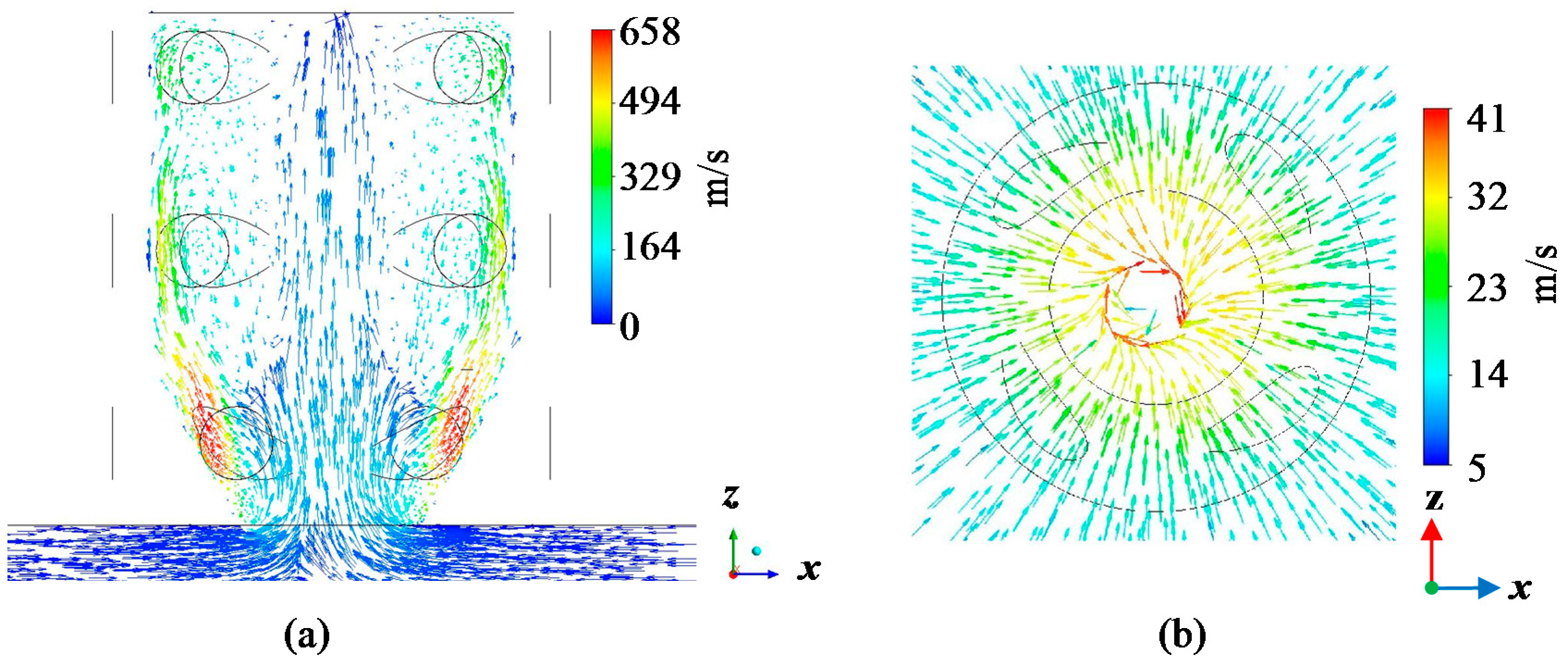
Figure 6.
Numerical results of flow velocity distribution along x-direction from center of nozzle at 2 mm above surface of machining material for gas inlet pressure of 300 kPa and gas outlet pressure of 30 kPa.
Figure 6.
Numerical results of flow velocity distribution along x-direction from center of nozzle at 2 mm above surface of machining material for gas inlet pressure of 300 kPa and gas outlet pressure of 30 kPa.

Figure 7.
Numerical results of (a) pressure contours (section view) and (b) pressure profile (top section view of nozzle at 2 mm above surface of machining material) for gas inlet pressure of 300 kPa and gas outlet pressure of 30 kPa.
Figure 7.
Numerical results of (a) pressure contours (section view) and (b) pressure profile (top section view of nozzle at 2 mm above surface of machining material) for gas inlet pressure of 300 kPa and gas outlet pressure of 30 kPa.
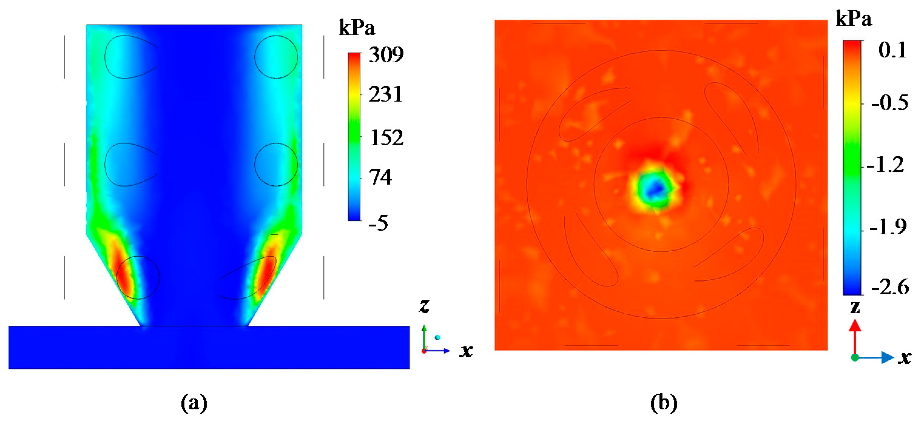
Figure 8.
Numerical results of pressure distribution along x-direction from center of nozzle at 2 mm above surface of machining material for gas inlet pressure of 300 kPa and gas outlet pressure of 30 kPa.
Figure 8.
Numerical results of pressure distribution along x-direction from center of nozzle at 2 mm above surface of machining material for gas inlet pressure of 300 kPa and gas outlet pressure of 30 kPa.
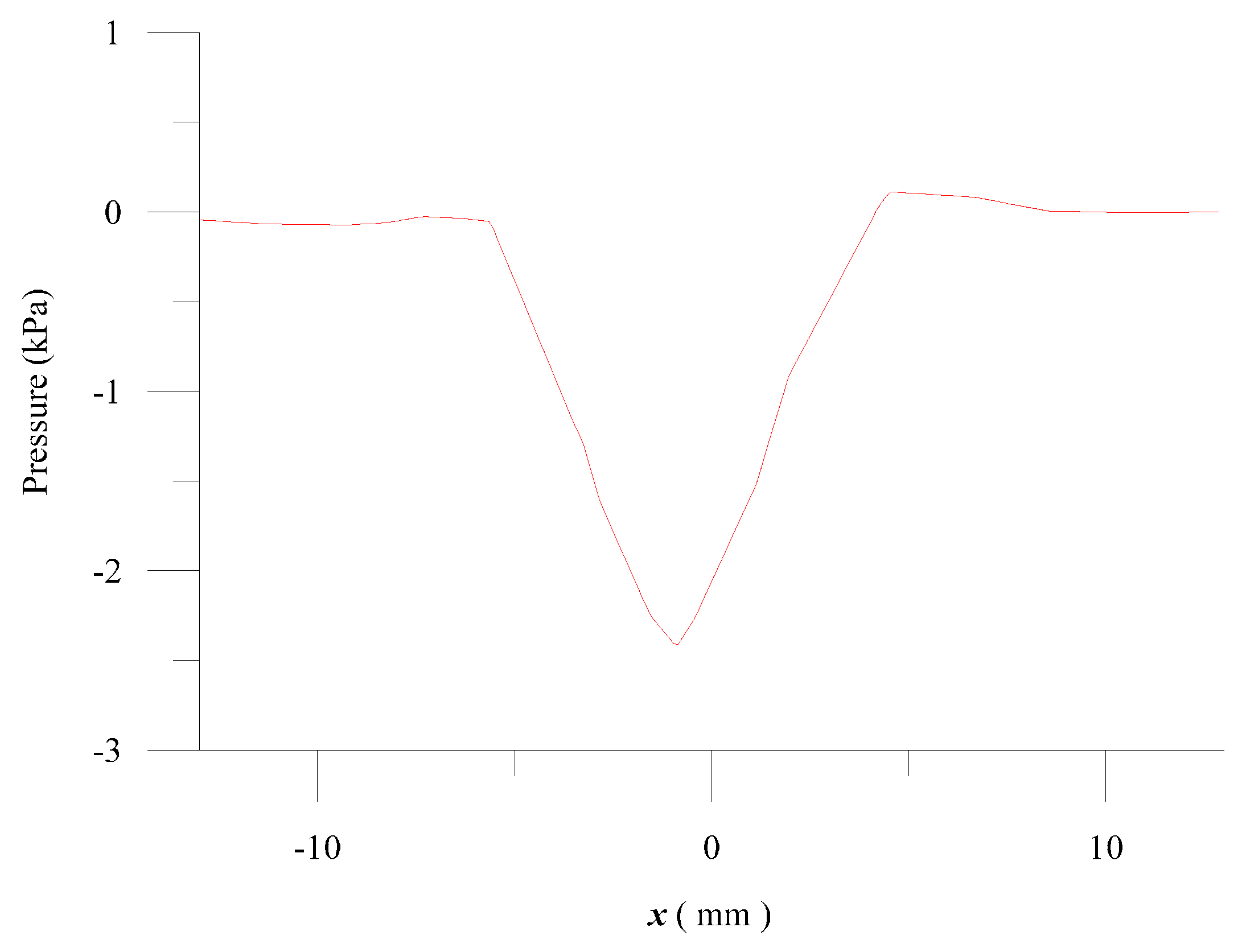
Figure 9.
(a) Experimental setup for gas flow visualization; (b) experimental results acquired by digital camera.
Figure 9.
(a) Experimental setup for gas flow visualization; (b) experimental results acquired by digital camera.
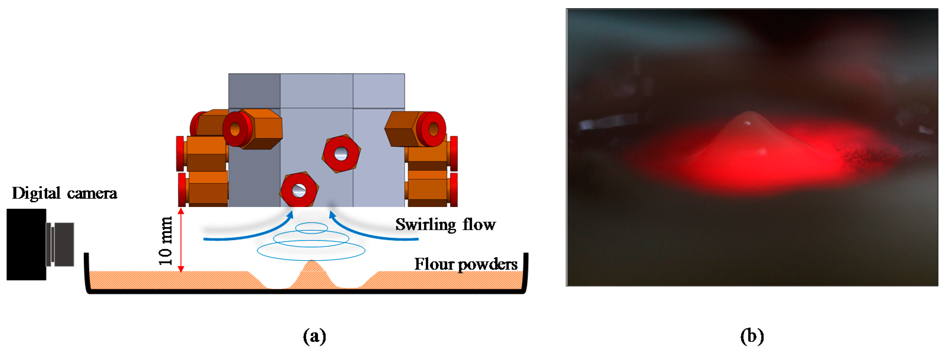
Figure 10.
(a) Experimental setup for assisted swirling nozzle for CO2 laser; (b) laser trepanning schematic layout.
Figure 10.
(a) Experimental setup for assisted swirling nozzle for CO2 laser; (b) laser trepanning schematic layout.
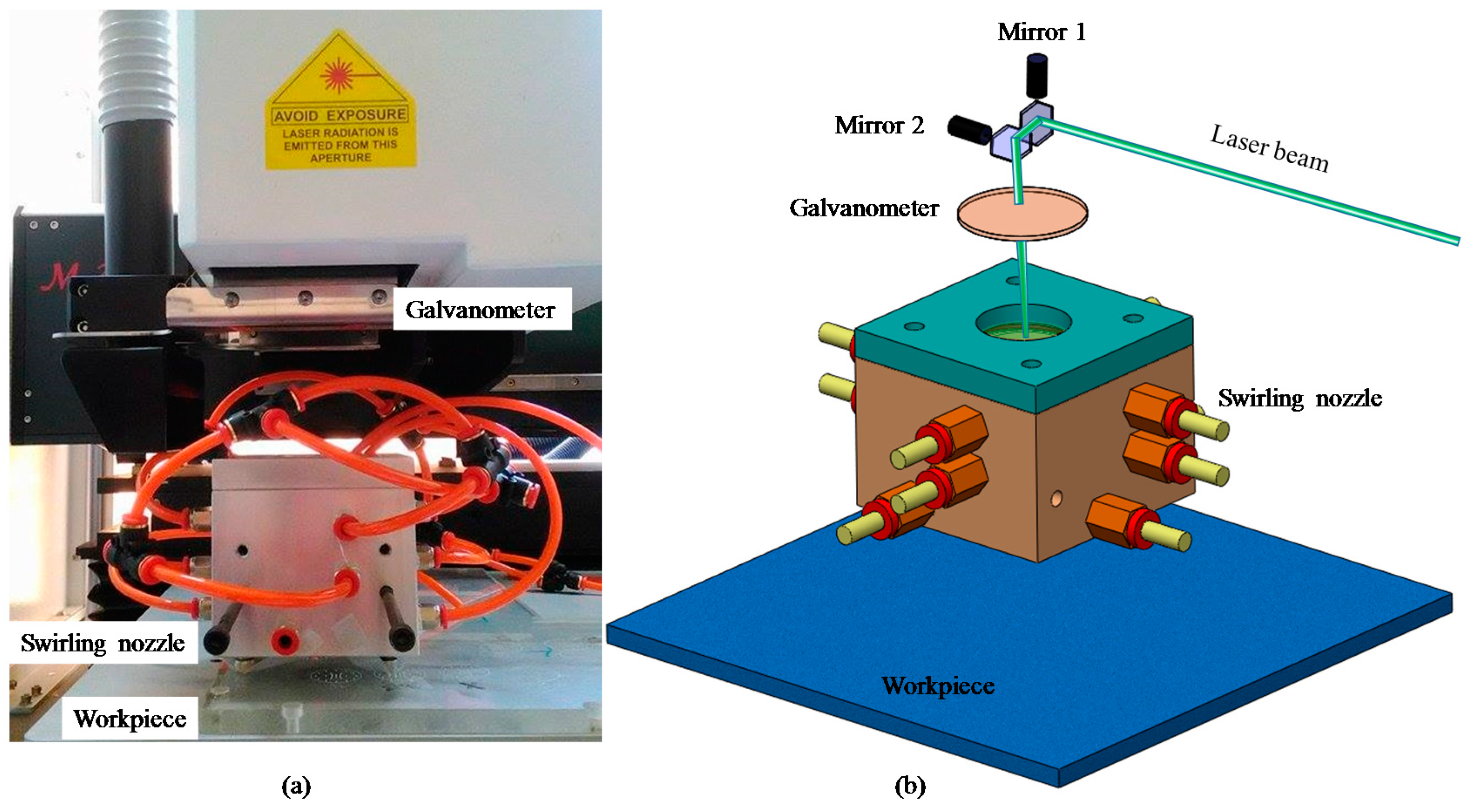
Figure 11.
Laser trepanning depth with different gas jet configurations (no gas jet, swirling gas jet, and straight gas jet) at different laser scanning speeds.
Figure 11.
Laser trepanning depth with different gas jet configurations (no gas jet, swirling gas jet, and straight gas jet) at different laser scanning speeds.

Figure 12.
Profile images of drilled holes with different gas jet configurations (no gas jet, straight gas jet, and swirling gas jet) at different laser scanning speeds.
Figure 12.
Profile images of drilled holes with different gas jet configurations (no gas jet, straight gas jet, and swirling gas jet) at different laser scanning speeds.

Figure 13.
Laser trepanning depth with different gas jet configurations (no gas jet, swirling gas jet, and straight gas het) at different trepanning diameters.
Figure 13.
Laser trepanning depth with different gas jet configurations (no gas jet, swirling gas jet, and straight gas het) at different trepanning diameters.
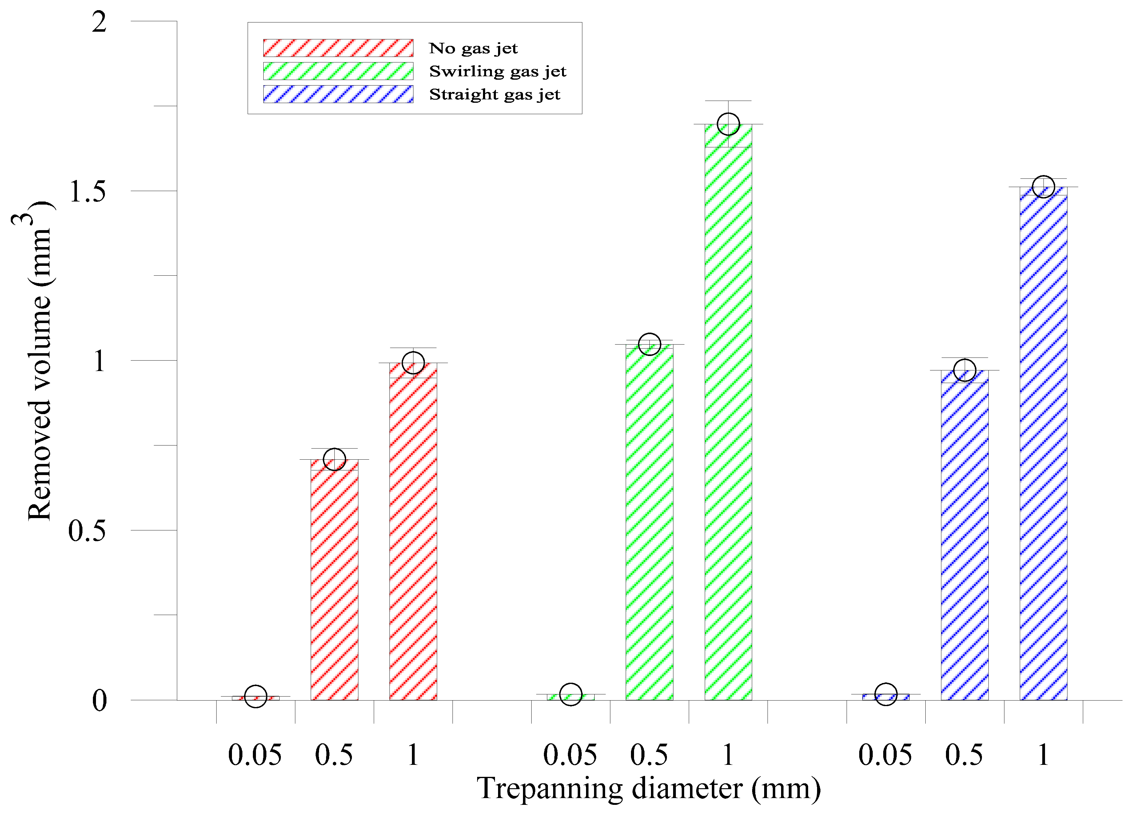
Figure 14.
Profile images of drilled holes with different gas jet configurations (no gas jet, swirling gas jet, and straight gas jet) at different trepanning diameters.
Figure 14.
Profile images of drilled holes with different gas jet configurations (no gas jet, swirling gas jet, and straight gas jet) at different trepanning diameters.

Table 1.
Simulation parameters.
| Analysis Type | Steady-State |
|---|---|
| Turbulence model | k-ε model |
| Air type | air at 25 °C |
| Boundary condition | Reference pressure: 1 atm |
| Gas inlet P1: 300 kPa | |
| Gas outlet P2: 30 kPa | |
| Minimum mesh size | 0.09 (mm) |
| Maximum mesh size | 18.70 (mm) |
| Number of mesh nodes | 43,791 |
| Mesh Elements | 225,630 |
Table 2.
Experimental conditions for laser trepanning depth comparison.
| Laser (Synrad Series 48 Model) | |
|---|---|
| Laser source | CO2 |
| Laser radiation energy | 10 W |
| Laser wavelength | 10.6 μm |
| Focal length | 170 mm |
| Beam quality | M2 < 1.2 |
| Beam diameter | 6.6 mm |
| Beam divergence | 4 mR |
| Rise time | <150 μs |
| Inlet gas pressure P1 | 300 kPa |
| Outlet gas pressure P2 | 30 kPa |
| Galvanometer scanner (Miniscan II, Raylase) | |
| Scan speed | 7000 mm/s |
| Repeatability | 20 μm |
| Field size | 100 × 100 mm2 |
© 2017 by the authors. Licensee MDPI, Basel, Switzerland. This article is an open access article distributed under the terms and conditions of the Creative Commons Attribution (CC BY) license (http://creativecommons.org/licenses/by/4.0/).
Share and Cite
MDPI and ACS Style
Ho, C.-C.; Shen, K.-Y.; Chen, C.-S.; Chang, Y.-J.; Hsu, J.-C.; Kuo, C.-L. Swirling Gas Jet-Assisted Laser Trepanning for a Galvanometer-Scanned CO2 Laser. Appl. Sci. 2017, 7, 502. https://doi.org/10.3390/app7050502
AMA Style
Ho C-C, Shen K-Y, Chen C-S, Chang Y-J, Hsu J-C, Kuo C-L. Swirling Gas Jet-Assisted Laser Trepanning for a Galvanometer-Scanned CO2 Laser. Applied Sciences. 2017; 7(5):502. https://doi.org/10.3390/app7050502
Chicago/Turabian StyleHo, Chao-Ching, Ke-Ying Shen, Chang-Sheng Chen, Yuan-Jen Chang, Jin-Chen Hsu, and Chia-Lung Kuo. 2017. "Swirling Gas Jet-Assisted Laser Trepanning for a Galvanometer-Scanned CO2 Laser" Applied Sciences 7, no. 5: 502. https://doi.org/10.3390/app7050502
Note that from the first issue of 2016, this journal uses article numbers instead of page numbers. See further details here.