Article

On the Visualization of Gas Metal Arc Welding Plasma and the Relationship Between Arc Length and Voltage

by
Emanuel B. F. Dos Santos
1,*,
Letícia H. Kuroiwa
1,†,
A. Felipe C. Ferreira
1,‡,
Rob Pistor
2 and
Adrian P. Gerlich
1
1
Centre for Advanced Materials Joining (CAMJ), Department of Mechanical and Mechatronics Engineering, University of Waterloo, 200 University Avenue West, Waterloo, ON N2L 3G1, Canada
2
Liburdi Engineering Limited, 400 Highway 6 North, Dundas, ON L9H 7K4, Canada
*
Author to whom correspondence should be addressed.
Current address: Department of Materials Engineering, Federal University of Sao Carlos (UFSCar), Rodovia Washington Luís /km 235, São Carlos, CEP 13565-905, São Paulo, Brazil.
Current address: Department of Mechanical Engineering, Polytechnic Institute, Pontifical Catholic University of Minas Gerais (PUC Minas), Avenida Dom José Gaspar 500 , Belo Horizonte, CEP 30535-901, Minas Gerais, Brazil.
Appl. Sci. 2017, 7(5), 503; https://doi.org/10.3390/app7050503
Submission received: 18 March 2017 / Revised: 25 April 2017 / Accepted: 9 May 2017 / Published: 15 May 2017
(This article belongs to the Special Issue Gas Metal Arc Welding)

Abstract

:
In this article, the camera settings for high-speed imaging of the arc, metal transfer, and weld pool in gas metal arc welding (GMAW) are investigated. The results show that by only changing camera exposure times and the selection of narrow bandpass filters, images that reveal features of the arc such as the iron vapor-dominated region, metal transfer and weld pool behavior can be produced without the need for external light sources. Using the images acquired, the arc length was measured and the relationship between arc length and arc voltage is discussed. The results show that for low values of current, the measured welding voltage increases with increasing arc length; however, for high current values, the arc voltage increases even though the measured arc length becomes shorter. It is suggested that the increase in arc voltage for high values of welding current is due to the increased evaporation of the wire electrode which decreases the plasma temperature and consequently the arc plasma electrical conductivity.

Graphical Abstract

1. Introduction

In a recent publication, Egerland [1] initiated a discussion on the definition of arc length in gas metal arc welding (GMAW) and the relationship between arc length and welding arc voltage. The author pointed out that the arc length—defined as the distance from the tip of the welding electrode to the adjacent surface of the weld pool [2,3]—is obsolete and meaningless. This is especially apparent when one considers the whole range of arc welding processes that are currently available, such as advanced pulsed gas metal arc welding (GMAW-P) processes, controlled metal transfer [4,5], and some of the transfer modes observed in constant voltage GMAW such as streaming and rotating spray [6,7]. One of the difficulties associated with establishing a definition or reference standard is related to the precise identification of the electrode tip and the surface of the weld pool, as in the case of buried arc, making it impractical to determine an accurate measurement of this distance. The difficulties related to wire tip identification can lead to misleading results if the imaging technique is not appropriate.
According to Egerland [1], a more consistent definition of arc length would be to consider the distance between the tip of the wire electrode taper to the surface of the weld pool, in which case it would be applicable for both GMAW and GMAW-P. This definition, along with being more general, is physically more consistent, and agrees with the results of Hertel et al. [8,9] which show that depending on the amount of iron metal vapor present in the arc, less than 20% of the instantaneous current is flowing through the electrode tip. This is due to the shift in arc attachment position to the tapered region caused by the presence of a high concentration of iron vapor at the wire tip [10,11,12,13,14]. Therefore, the definition that the electric arc comprises the region between the electrode tip and the surface of the weld pool is not quite physically accurate.
Another question that arises from the current definition of arc length [2,3] is the statement of proportionality between arc voltage and arc length, well known to welders and even researchers actively working in the field of the science and technology of welding. Even if a precise arc length is measured according to the aforementioned standards, this statement is not accurate when comparing the voltage measured when transfer modes such as projected, streaming, and rotating spray [6,7,12,15,16,17] or advanced pulsed GMAW [1] are considered. This has been based on high-speed imaging and high-speed data acquisition of the welding electrical signals. The need to accurately describe arc length has practical implications for the development of parameters for welding procedures, and this work reveals the limitations of direct visual observation. However, regardless of the actual arc length, welding parameters and procedures will remain self-consistent, since they rely on contact tip to work piece distance, and the actual length is of greater relevance to research studies.
According to the literature, the structure of the electric arc in GMAW assumes a conical shape, and is divided in two distinct regions: an outer cone composed mostly of the ionized shielding gas, and an inner cone, which presents a high concentration of electrode metal vapor [8,9,10,11,12,13,18,19,20,21,22]. This arc structure has been reported via spectroscopy measurements [18,19,20,21,23], numerical simulations [8,9,24], and high-speed imaging experiments [25]. This last technique requires appropriate apparatus and settings to be employed in order to reveal the details of the different arc regions, metal transfer, and fume formation, in order to provide useful information regarding the welding process and metal transfer phenomenon.
Although high speed-imaging has long been used to study metal transfer and arc phenomena in welding, there is a lack of literature providing guidance on appropriate camera settings and filter selection for the observation of arc phenomena and metal transfer. Following preliminary trials and based on the observations of molten droplets performed by prior researchers [19,20,21,23,25,26], various filter wavelengths for visualization were selected, with frame rates and exposure times adjusted to reveal sufficient detail in droplet shapes (while disregarding unimportant overexposed areas). In this regard, this article presents high-speed images of GMAW plasma using different camera settings and filter selections. In addition, the relationship between arc length and arc voltage is discussed.

2. Materials and Methods

In order to investigate the influence of both low and high values of current, pulsed GMAW was used. The power source used was a Liburdi Dimetrics GoldTrack VI (Liburdi Engineering Limited, Dundas, ON, Canada), which provides a current pulse profile with nearly ideal square pulse shape [27].
For the metal transfer and arc phenomenon imaging, a high-speed camera (FASTCAM Mini UX50, Photron, San Diego, CA, USA) was used. The lens used was a C-mount close focus zoom lens (6X, 18–108 mm FL, Edmund Optics Inc., Barrington, NJ, USA) equipped with a 25/25.4 mm diameter C-mount lens mount (Thick Lens Mount from Edmund Optics Inc., Edmund Optics Inc., Barrington, NJ, USA) with a holder to incorporate band-pass filters, which were used to limit the amount of light from the arc reaching the camera sensor. This would reveal different features of the arc and/or molten metal at both wire electrode and weld pool. The lens aperture was fixed at f/22, and the high-speed camera recording the arc at a frequency of 5000 frames per second, synchronized with a data acquisition system (DAQ) which was recording the welding current and voltage at a frequency of 20 kHz for a period of 1 s.
Bandpass interference filters (Edmund Optics Inc., Barrington, NJ, USA) of two wavelengths — 515 ± 10 and 900 ± 10 nm — were used. The 515 ± 10 nm wavelength allowed the imaging of the features in the arc core, which is composed mostly of iron vapor. The imaging of iron vapor is possible owing to the fact that iron has a strong peak emission line at a 516.74 nm wavelength [28,29,30]. To capture the outer cone of the electric arc, droplet formation and transfer, and weld pool dynamics, a narrow band pass filter of 900 ± 10 nm wavelength was used. The lens aperture was fixed at f/22 and different exposure times were used.
All the welds were performed using bead on plate welds performed using AWS A5.18 ER70S-6 wire of 1.2 mm (0.045”) nominal diameter. The base metal was 1020 steel plates of 9.5 mm thickness, and contact tip to workpiece distance of 20 mm. The shielding gas used was a mixture of 85% Ar-15% CO 2 at at flow rate of 18.9 L/min (40 cfh).

3. Results and Discussion

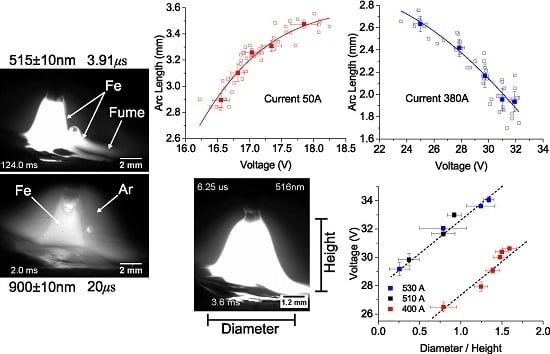
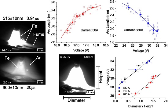
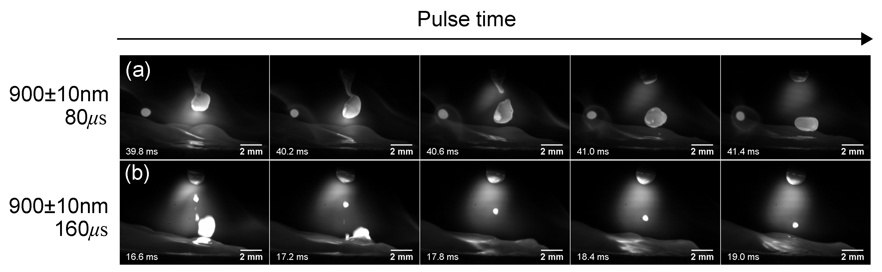
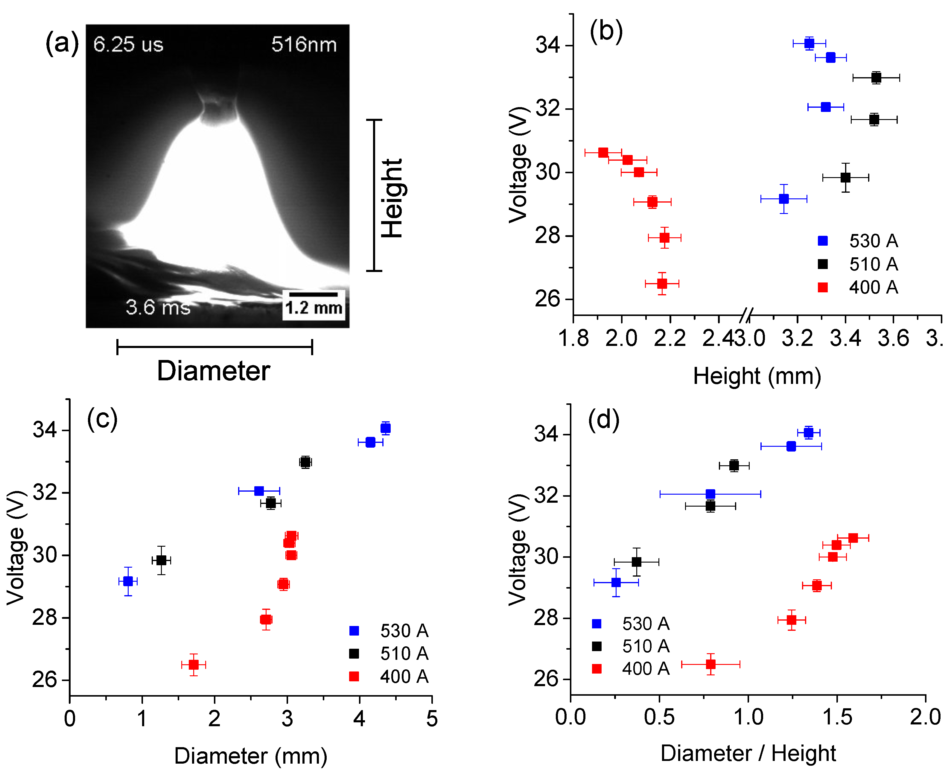
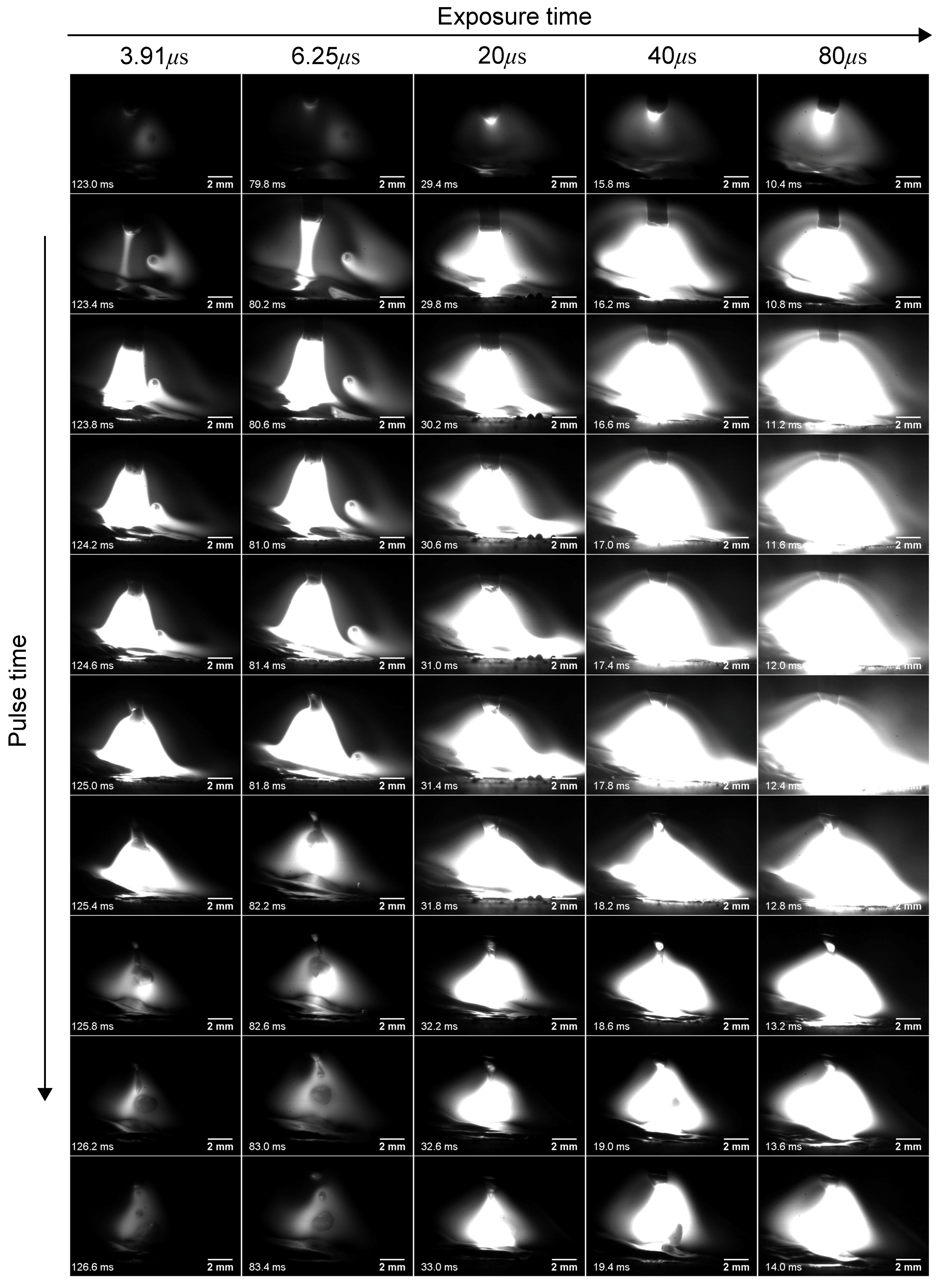
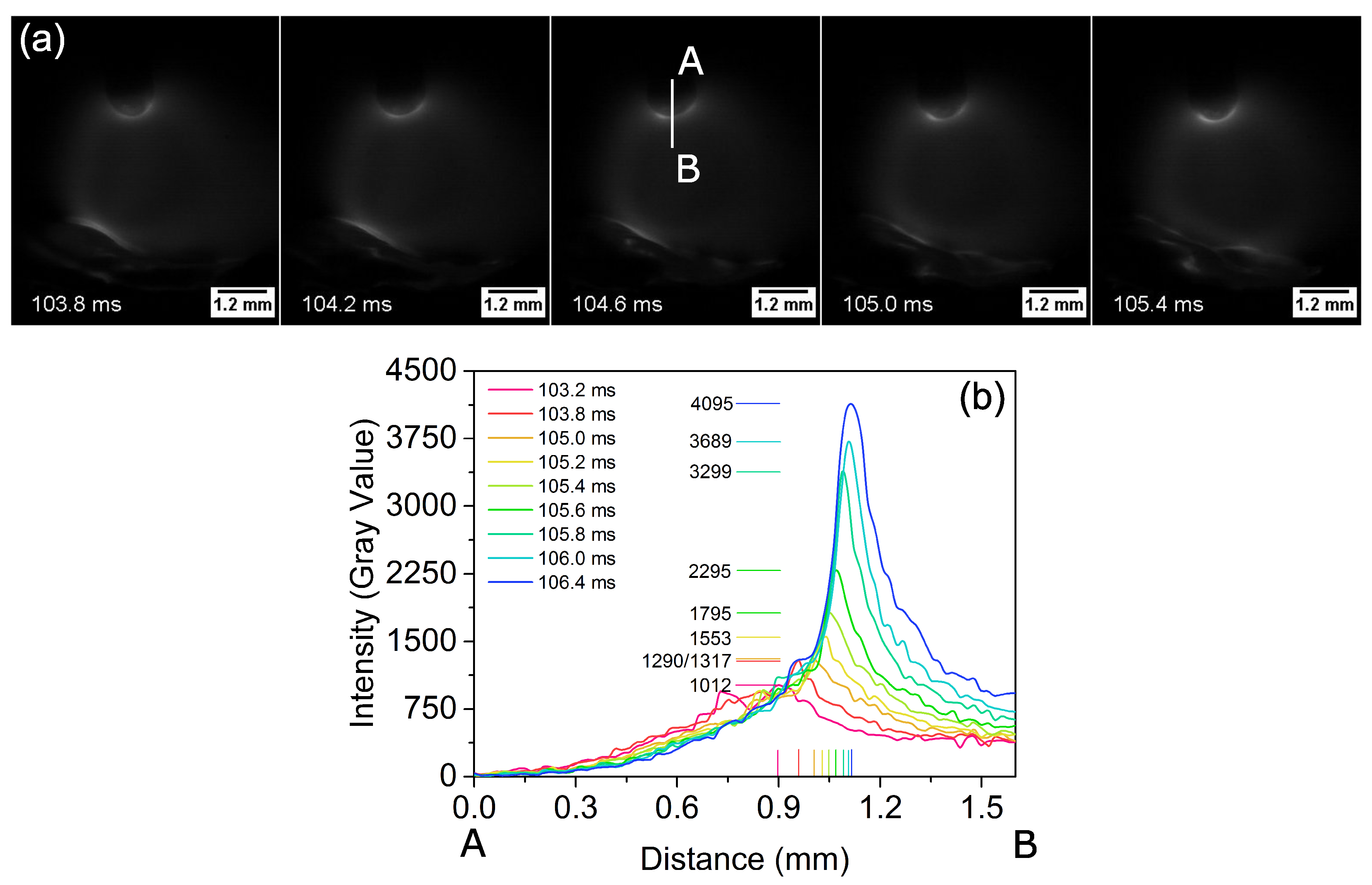
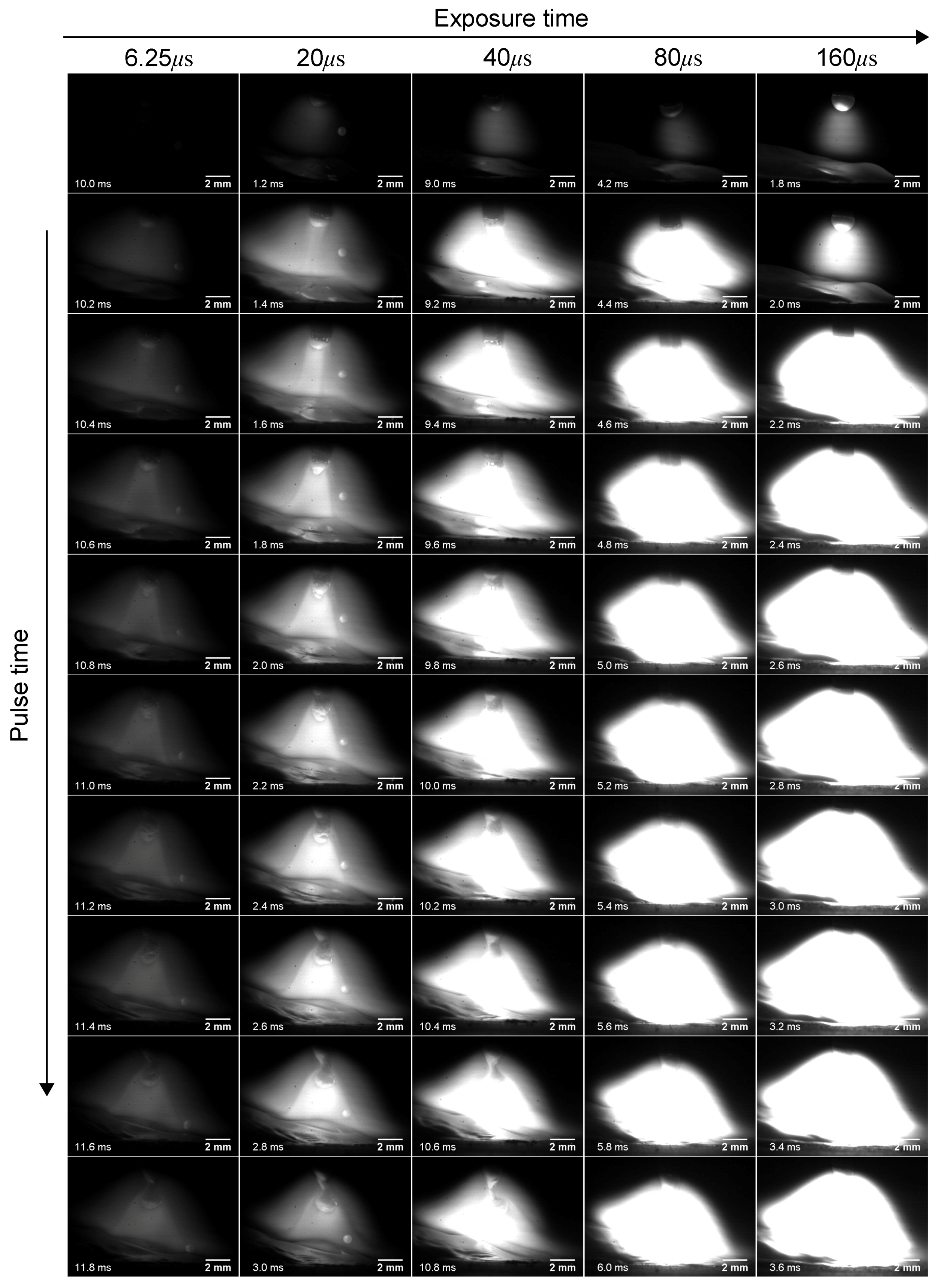
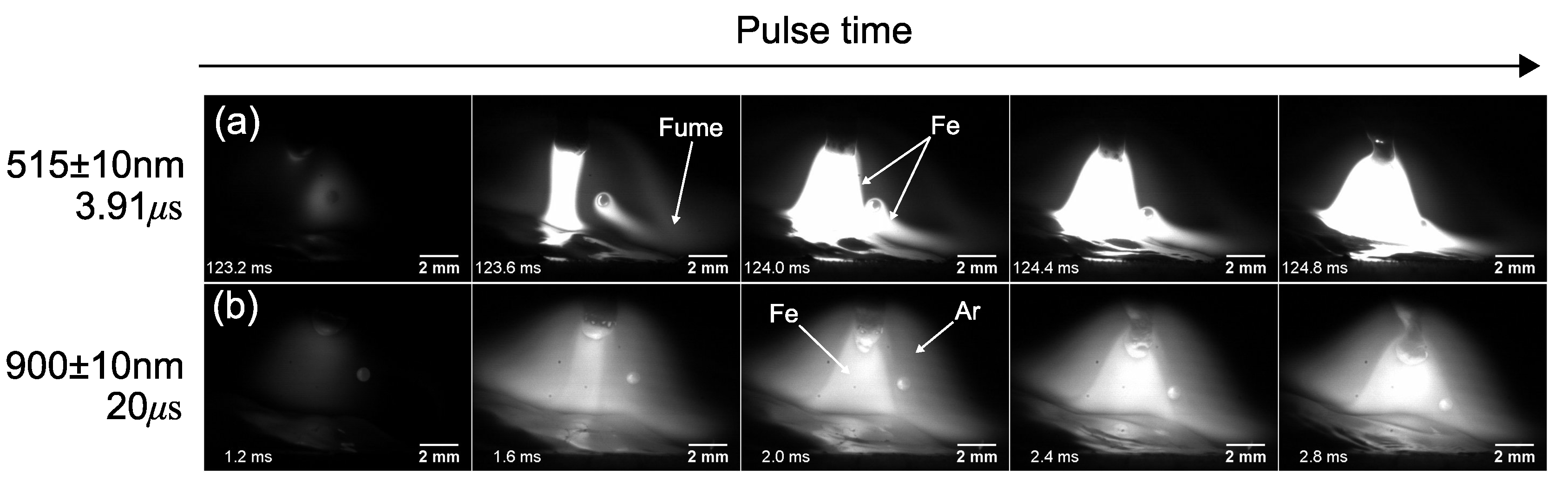
3.1. High-Speed Imaging

In this section the results of the high-speed imaging are presented. Different camera settings were used to reveal different features of the arc phenomena and metal transfer. The results presented in this section were produced using a wire feeding speed of 150 ipm; travel speed of 7.5 ipm; peak current I p = 400 A; background current I p = 50 A; pulse frequency of 90 Hz; and voltage of 20 V.
Figure 1 shows the images acquired when the arc radiation was filtered with a 515 ± 10 nm narrow band pass filter for different camera sensor exposure times from 3.91 to 80 μ s. Each column in this figure shows the images from the start of peak phase to the onset of background current. Iron (Fe) has a strong emission peak (Fe I) at a wavelength of 516.74 nm [28,29], and hence using a narrow band pass filter of 515 ± 10 nm wavelength will selectively allow exposure to radiation mostly from Fe I. Hence, the bright regions on these images are composed mostly of iron vapor. Although iron has a peak emission line at 515 ± 10 nm wavelength, some other radiation is also able to reach the camera sensor. Consequently, increasing exposure time will allow more radiation to reach the camera sensor, over-exposing the image, leading to image flare. This can be seen on the fifth row of Figure 1 for the exposure times of 20, 40, and 80 μ s.
Despite the image flare due to the excessive sensor exposure, the exposure times of 3.91 and 6.25 μ s provide clear images of the iron vapor core formation and evolution during the peak current pulse. In Figure 1 at the times of 123.0 and 79.8 ms for the exposure time of 3.91 and 6.25 μ s, respectively, the light captured by the camera sensor is being emitted from the wire tip, weld pool, and the small droplet being transferred. Those regions are the main sources of iron vapor, owing to their high surface temperatures [11,13]. As the current increases to the peak phase, the amount of vapor emitted from the wire tip increases due to the increase in wire tip temperature. This evolution of metal vapor region has been repeatedly predicted by numerical simulations [8,9,13] and reported in studies utilizing high-speed imaging [25]. Additionally, in Figure 1 for the exposure time of 3.91 and 6.25 μ s, one can see that the metal vapor around the secondary droplet is pushed downward away from the molten pool as the pulse current increases to a peak value, owing to the increase in plasma flow velocity as a consequence of the current increase [10]. This metal vapor pushed to lower temperature regions of the arc will allow the nucleation and growth of nanoparticles by condensation, leading to fume formation [13,31] (see Supplemental Video S1 for details).
Given that when the 515 ± 10 nm wavelength filter is used, the image brightness is proportional to the amount of high temperature iron vapor, one could use this information to correlate the image pixel intensity to the amount of iron vapor present in a specific region. This is shown on Figure 2, where images were taken during the background current phase with an exposure time of 80 μ s. The evolution of pixel intensities along line A in Figure 2a are plotted in Figure 2b. It can be seen that the pixel intensity (gray value) increases with time, indicating an increase in the amount of iron metal vapor in the wire tip. This is in agreement with numerical simulation of Boselli et al. [13], where it was shown that during background current phase, iron vapor accumulates at the wire tip and is not dragged down by the plasma flow due to the low flow velocities associated with small current values.
In Figure 3, the evolution of arc and droplet formation during the current pulse peak phase (for the same welding conditions corresponding to Figure 1) are shown for different exposure times when a 900 ± 10 nm wavelength bandpass filter is used. In this figure, the camera exposure time is varied from 6.25 to 160 μ s. Compared to images acquired with the 516 ± 10 nm filter, these images provide more details of the droplet formation sequence and weld pool motion. Using an exposure time of 20 μ s enables the simultaneous visualization of the arc, droplet formation, and molten pool motion. Indeed, at an exposure time of 20 μ s, one can distinguish an inner brighter cone in the arc, which can be compared to the 515 ± 10 nm wavelength filter to reveal that this brighter inner cone is the iron vapor core of the arc. This is shown in Figure 4, where the snapshots using both filters are compared at equivalent pulse times. Therefore, the 900 ± 10 nm wavelength filter enables visualization of both regions of the arc; i.e., the inner cone with a high fraction of iron vapor and the outer cone composed of mostly ionized shielding gas, which is Ar in the present investigation (see Figure 4b).
For all the filters and camera settings tested in this work, it was found that when the 900 ± 10 nm wavelength filter is used with camera exposure time of 80 and 160 μ s, it provides clear pictures of the events occurring during the background phase of current pulse profiles, allowing droplet transfer and weld pool motion to be monitored, as shown in Figure 5. Supplemental Video S2 shows a comparison of all the settings investigated.

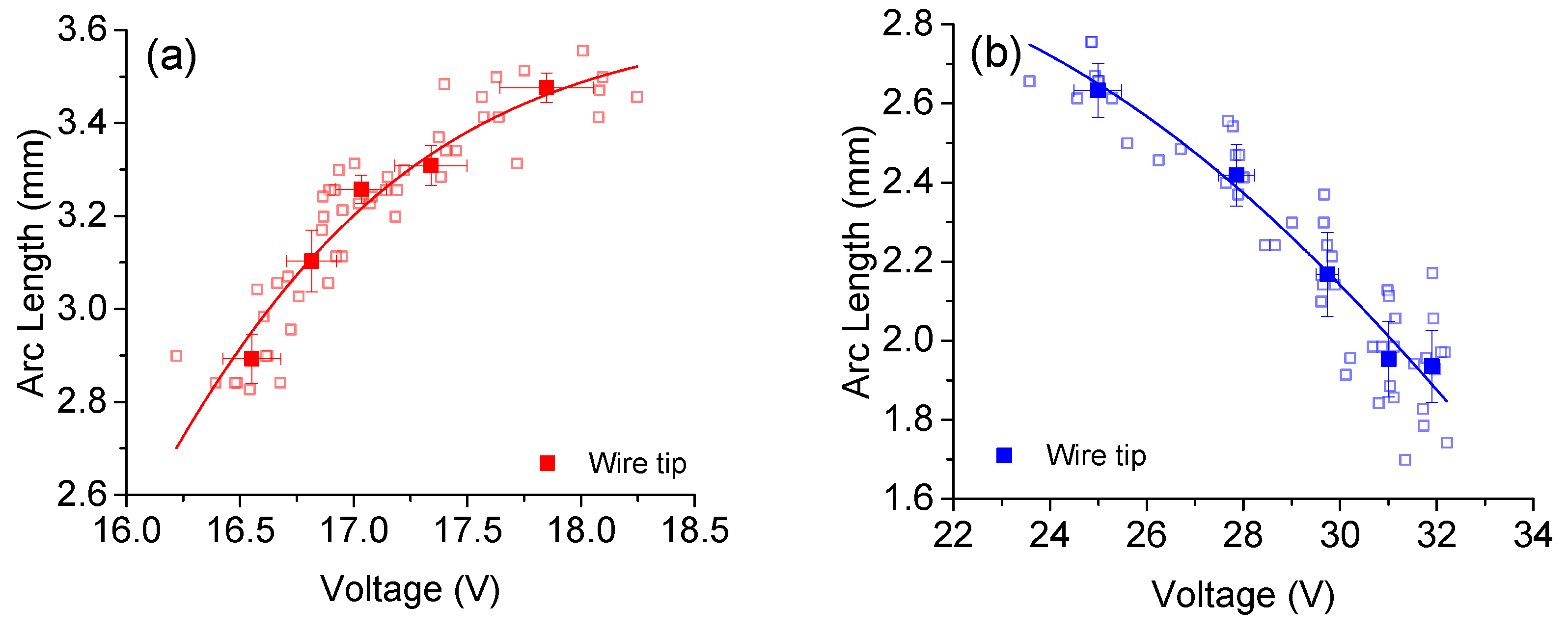
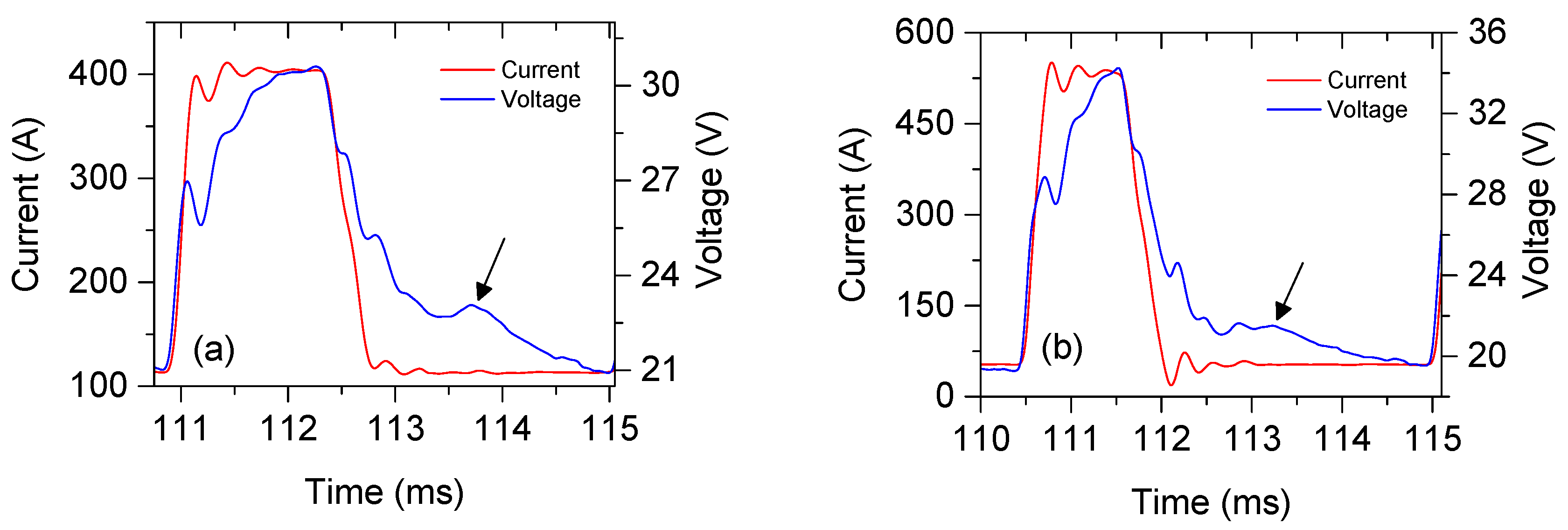
3.2. Arc Voltage and Arc Length

Figure 6 shows the electric signals, featuring the variation of arc voltage as the current pulse progress. As can be seen in this figure, current values are nearly constant during the peak and background current phases. From Figure 4, one can see that as the pulse progresses during peak phase, the distance between electrode tip and weld pool decreases; however, the voltage is still increasing (see Figure 6). Despite that, the measured voltage increases during the peak phase, while the measured arc voltage decreases during background current (Figure 6). Additionally, notice a secondary peak in voltage signal during background current, indicated by the arrows. These occur following the moment of droplet detachment (see details in [27]).
Arc length was measured (corresponding to the distance between wire tip and weld pool [2,3]) for current values of 50 and 380 A, and the result is shown in Figure 7. For low values of welding current (i.e., during the background phase), one can see in Figure 7a that voltage increases with the measured arc length. On the other hand, for higher values of welding current (as shown in Figure 7b), the measured arc voltage increases, even though the measured arc length decreases. A voltage fall in the GMAW arc column around 0.69–1.0 V/mm is recognized in the literature [32,33,34], and the results in Figure 7b contradict this widely-accepted proportionality between arc voltage and arc length. In Figure 4 it is possible to observe that the tapering position of the electrode does not shift upwards by a large amount. Even if one measures arc length as the distance between the beginning of the electrode tapered region and the weld pool [1], it would verify that arc voltage increases at a much higher rate than 0.69–1.0 V/mm [32,33].
In Figure 4, although the current value is the same (i.e., 400 A), one can note that as the pulse progresses during peak phase, the shape of the iron vapor-dominated arc core is changing, which is due to the increasing amount of vapor generated. The height and diameter of this region was measured according to Figure 8a for different current values. The variation of arc voltage with the height of this region is shown in Figure 8b, where one can see that there is no clear relationship between these quantities, despite the fact that for a current of 400 A the voltage seems to decrease with increasing core height. In Figure 8c, the instantaneous voltage is plotted against the bottom diameter of this region, and one can note that voltage is proportional to the measured diameter. If arc voltage is plotted against the diameter/height ratios, the values have a linear relationship, as it is shown in Figure 8d. The linear relationship between measured voltage and the ratio between core diameter over height shown in Figure 8d is correlated to the decrease in column height as diameter increases.
The physical basis for the increase of voltage with arc core diameter here is attributed to the fact that the bottom diameter increases with increasing amount of metal vapor formed, which will cause the cooling of the arc plasma and a consequent decrease in the arc plasma conductivity [10,11]. Hertel et al. [8,9] observed a shift in the arc attachment at the wire electrode tapering region, rather than the wire tip, and attributed this phenomenon to the decrease of electrical conductivity of the plasma at the tip of the wire electrode. This is caused by the high vaporization rate of the electrode tip, which cools down the plasma at this region decreasing its electrical conductivity, and subsequently increases the actual arc length, contributing to the increase in arc voltage. Additionally, the increase in the diameter of the arc core due to an increase in the fraction of iron metal vapor represents an increase in the cathode area, consequently increasing the overall voltage fall in the cathode.
Therefore, it is possible that the proportionality between arc length and voltage only holds when considering the different welding transfer modes in constant voltage GMAW (e.g., short-circuit, globular, and spray), due to the fact that those transfer modes occur at increasing values of current and the average arc length over time is larger. However, due to sudden change in welding current in pulsed GMAW welding, the arc dynamics are altered and arc voltage is not proportional to arc length, and the present study involving a nearly ideal square wave pulse exemplifies one of the cases where the estimation of arc length (as defined in prior work [2,3]) does not hold consistent.

4. Conclusions

This article presents high-speed images of metal transfer in pulsed GMAW acquired at different settings. Two narrow bandpass filters were used with varying camera exposure times to yield quality images revealing the features of the arc, droplet, and weld pool, without a need for external light sources. These are useful results, given that it provides guidelines for producing images that contain useful information regarding arc behavior, metal transfer, and weld pool phenomena for those who study these features either numerically or experimentally.
Using the images acquired, arc length was measured, as defined by the British Standard Institute [2] and American Welding Society [3], and the relationship between arc length and arc voltage was evaluated. It was found that for low values of current, when the electrode vaporization rates are low, the proportionality between arc voltage and arc length holds true; however, for higher current values, where increased vaporization of the wire electrode tip occurs, the measured welding voltage increases, even though the arc length decreases. For high values of welding current, the results suggest a relationship between the measured welding voltage and the diameter of the arc core, which is composed of a high fraction of iron vapor. There appears to be a linear relationship for different current values, but further study is required to generalize this relationship. This discussion on the arc length aims to corroborate the discussion of Egerland [1], which points to the need for a more rigorous definition of arc length which includes the variety of weld processes available.

Supplementary Materials

The following are available online at https://www.mdpi.com/2076-3417/7/5/503/s1, Video S1: This video shows the drag of metal vapor from the secondary droplet to lower temperatures arc regions leading to fume formation, Video S2: Comparison of arc plasma and metal transfer for different camera settings and filter selections.

Acknowledgments

The authors acknowledge Natural Science and Engineering Research Council of Canada (NSERC) and TransCanada Pipeline Ltd. for the financial support and Liburdi Engineering Limited for the technical support.

Author Contributions

E.B.F.D.S. conceived, designed and performed the experiments; L.H.K. and A.F.C.F. assisted with measurements and data collection; R.P. and A.P.G. contributed to the discussion of the experimental data; E.B.F.D.S. and A.P.G. wrote the paper.

Conflicts of Interest

The authors declare no conflict of interest. The founding sponsors had no role in the design of the study; in the collection, analyses, or interpretation of data; in the writing of the manuscript, and in the decision to publish the results.

References

  1. Egerland, S. A Contribution to Arc Length Discussion. Soldagem Inspeção 2015, 20, 367–380. [Google Scholar] [CrossRef]
  2. BSI. British Standard BS 499-1:2009: Welding Terms and Symbols Part 1: Glossary for Welding, Brazing and Thermal Cutting; British Standards Institution: London, UK, 2009. [Google Scholar]
  3. American Welding Society (AWS). AWS Standard A3.0M/A3.0:2010: Welding Terms and Definitions: Including Terms for Adhesive Bonding, Brazing, Soldering, Thermal Cutting, and Thermal Spraying; American Welding Society: Miami, FL, USA, 2010; p. 162. [Google Scholar]
  4. Lincoln Electric. Surface Tension Transfer (STT); Lincoln Electric: Cleveland, OH, USA, 2005; p. 4. [Google Scholar]
  5. Fronius. CMT: Cold Metal Transfer; Fronius: Wels, Austria, 2013; p. 8. [Google Scholar]
  6. Scotti, A. Mapping Transfer Modes for Stainless Steel Gas Metal Arc Welding. Sci. Technol. Weld. Join. 2000, 5, 227–234. [Google Scholar] [CrossRef]
  7. Scotti, A.; Ponomarev, V.; Lucas, W. A scientific application oriented classification for metal transfer modes in GMA welding. J. Mater. Process. Technol. 2012, 212, 1406–1413. [Google Scholar] [CrossRef]
  8. Hertel, M.; Spille-Kohoff, A.; Füssel, U.; Schnick, M. Numerical simulation of droplet detachment in pulsed gas–metal arc welding including the influence of metal vapour. J. Phys. D Appl. Phys. 2013, 46, 224003. [Google Scholar] [CrossRef]
  9. Hertel, M.; Rose, S.; Füssel, U. Numerical simulation of arc and droplet transfer in pulsed GMAW of mild steel in argon. Weld. World 2016, 60, 1055–1061. [Google Scholar] [CrossRef]
  10. Schnick, M.; Füssel, U.; Hertel, M.; Spille-Kohoff, A.; Murphy, A.B. Metal vapour causes a central minimum in arc temperature in gas–metal arc welding through increased radiative emission. J. Phys. D Appl. Phys. 2009, 43, 022001. [Google Scholar] [CrossRef]
  11. Murphy, A.B. The effects of metal vapour in arc welding. J. Phys. D Appl. Phys. 2010, 43, 165204. [Google Scholar] [CrossRef]
  12. Schnick, M.; Fuessel, U.; Hertel, M.; Spille-Kohoff, A.; Murphy, A.B. Numerical investigations of arc behaviour in gas metal arc welding using ANSYS CFX. Front. Mater. Sci. 2011, 5, 98–108. [Google Scholar] [CrossRef]
  13. Boselli, M.; Colombo, V.; Ghedini, E.; Gherardi, M.; Sanibondi, P. Dynamic analysis of droplet transfer in gas–metal arc welding: modelling and experiments. Plasma Sources Sci. Technol. 2012, 21, 055015. [Google Scholar] [CrossRef]
  14. Ogino, Y.; Hirata, Y.; Murphy, A.B. Numerical simulation of GMAW process using Ar and an Ar–CO2 gas mixture. Weld. World 2016, 60, 345–353. [Google Scholar] [CrossRef]
  15. Kim, Y.S.; Mceligot, D.M.; Eagar, T.W. Analyses of Electrode Heat Transfer in Gas Metal Arc Welding. Weld. J. 1991, 1, 20–31. [Google Scholar]
  16. Kim, Y.S.; Eagar, T.W. Analysis of metal transfer in gas metal arc welding. Weld. J. 1993, 72, 269s–278s. [Google Scholar]
  17. Jones, L.A.; Eagar, T.W.; Lang, J.H. Images of a Steel Electrode in Ar-2% O2 Shielding during Constant Current Gas Metal Arc Welding. Weld. J. 1998, 77, 135S–141S. [Google Scholar]
  18. Goecke, S.F. Auswirkungen von Aktivgaszumischungen im vpm-Bereich zu Argon auf das MIG- Impulsschweißen von Aluminium. Ph.D. Thesis, Technischen Universität Berlin, Berlin, Germany, 2005. [Google Scholar]
  19. Zielinska, S.; Musioł, K.; Dzierżȩga, K.; Pellerin, S.; Valensi, F.; de Izarra, C.; Briand, F. Investigations of GMAW plasma by optical emission spectroscopy. Plasma Sources Sci. Technol. 2007, 16, 832–838. [Google Scholar] [CrossRef]
  20. Zielinska, S.; Pellerin, S.; Valensi, F.; Dzierzega, K.; Musiol, K.; de Izarra, C.; Briand, F. Gas influence on the arc shape in MIG-MAG welding. Eur. Phys. J. Appl. Phys. 2008, 43, 111–122. [Google Scholar] [CrossRef]
  21. Gött, G.; Schöpp, H.; Hofmann, F.; Heinz, G. Improvement of the control of a gas metal arc welding process. Meas. Sci. Technol. 2010, 21, 25201. [Google Scholar] [CrossRef]
  22. Schnick, M.; Füssel, U.; Hertel, M.; Rose, S.; Haessler, M.; Spille-Kohoff, A.; Murphy, A.B. Numerical Investigations of the Influence of Metal Vapour in GMA Welding. Weld. World 2011, 55, 114–120. [Google Scholar] [CrossRef]
  23. Rouffet, M.E.; Wendt, M.; Goett, G.; Kozakov, R.; Schoepp, H.; Weltmann, K.D.; Uhrlandt, D. Spectroscopic investigation of the high-current phase of a pulsed GMAW process. J. Phys. D Appl. Phys. 2010, 43, 434003. [Google Scholar] [CrossRef]
  24. Schnick, M.; Hertel, M.; Fuessel, U.; Uhrlandt, D. Energy balance in MIG arcs. J. Phys. D Appl. Phys. 2013, 46, 224002. [Google Scholar] [CrossRef]
  25. Nomura, K.; Kataoka, K.; Mimura, K.; Hirata, Y.; Kishi, T. Tomographic spectroscopic observation of argon and metal vapor behavior in MIG arc welding. Weld. World 2016, 60, 117–125. [Google Scholar] [CrossRef]
  26. Kadoi, K.; Fujinaga, A.; Yamamoto, M.; Shinozaki, K. The effect of welding conditions on solidification cracking susceptibility of type 310S stainless steel during laser welding using an in-situ observation technique. Weld. World 2013, 57, 383–390. [Google Scholar] [CrossRef]
  27. Dos Santos, E.B.F.; Pistor, R.; Gerlich, A.P. Pulse profile and metal transfer in pulsed gas metal arc welding: Droplet formation, detachment and velocity. Sci. Technol. Weld. Join. 2017, 1–15. [Google Scholar] [CrossRef]
  28. Nave, G.; Johansson, S.; Learner, R.C.M.; Thorne, A.P.; Brault, J.W. A new multiplet table for Fe I. Astrophys. J. Suppl. Ser. 1994, 94, 221–459. [Google Scholar] [CrossRef]
  29. Yamashita, S.; Fujinaga, A.; Yamamoto, M.; Shinozaki, K.; Kadoi, K.; Mitsui, K.; Usui, H. In-situ Temperature Measurement using Monochrome High-speed Sensors during Laser Welding. Q. J. Jpn. Weld. Soc. 2013, 31, 78s–81s. [Google Scholar] [CrossRef]
  30. Kramida, A.; Ralchenko, Y.; Reader, J.; Team, N.A. NIST Atomic Spectra Database (ver. 5.3); National Institute of Standards and Technology: Gaithersburg, MD, USA, 2015. Available online: http://physics.nist.gov/asd (accessed on 10 February 2017).
  31. Park, H.; Mudra, M.; Trautmann, M.; Murphy, A.B. A Coupled Chemical Kinetic and Nucleation Model of Fume Formation in Metal–Inert-Gas/Metal–Active-Gas Welding. Plasma Chem. Plasma Process. 2017, 37, 805–823. [Google Scholar] [CrossRef]
  32. Lancaster, J.F. The Physics of Welding, 2nd ed.; Pregamon Press: Oxford, UK, 1986; p. 360. [Google Scholar]
  33. Lancaster, J. The physics of fusion welding. Part 1: The electric arc in welding. IEE Proc. B Electr. Power Appl. 1987, 134, 233–254. [Google Scholar] [CrossRef]
  34. McIntosh, C.; Mendez, P.F. Experimental measurements of fall voltages in gas metal arc welding. Weld. J. 2017, 96, 121s–132s. [Google Scholar]
Figure 1. Arc appearance for aperture of f/22 using at narrow band pass filter of 515 ± 10 nm wavelength for different camera sensor exposure times.
Applsci 07 00503 g001
Figure 2. Pixel intensity at wire tip for a current of 55 A, observed with an aperture of f/22 using at narrow band pass filter of 515 ± 10 nm wavelength and exposure time of 80 μ s: (a) frames of the high speed image, (b) pixel intensity plotted.
Applsci 07 00503 g002
Figure 3. Arc appearance for aperture of f/22 using at narrow band pass filter of 900 ± 10 nm wavelength for different camera sensor exposure times.
Applsci 07 00503 g003
Figure 4. Iron (Fe) metal vapour and argon (Ar) dominated regions during pulse peak phase (current of 400 A) captured using different bandpass filters and exposure times: (a) 515 ± 10 nm filter and exposure time of 3.91 μ s, (b) 900 ± 10 nm filter and exposure time of 20 μ s.
Applsci 07 00503 g004
Figure 5. Bandpass filters and exposure times that can be used for (a) droplet temperature measurement and (b) weld pool behavior (current 50 A) captured using different bandpass filters and exposure times.
Applsci 07 00503 g005
Figure 6. Variation of current and voltage for peak current of (a) 400 A and (b) 530 A.
Applsci 07 00503 g006
Figure 7. Variation of welding voltage with arc length for current values of (a) 50 A and (b) 380 A.
Applsci 07 00503 g007
Figure 8. (a) schematic geometric features measured; variation of welding voltage with metal vapor column (b) height, (c) diameter at the cathode, and (d) ratio between diameter and height. The high-speed images were taken using the 515 ± 10 nm wavelength filter, exposure time of 6.25 μ s, and lens aperture of f/22.
Applsci 07 00503 g008

