Construction of Nonblocking Wavelength/Space Switches with AWGs and WSSes

1
Department of Applied Math, National University of Tainan, Tainan 70005, Taiwan
2
Department of ECE, Hong Kong University of Science of Technology, Hong Kong, China
*
Author to whom correspondence should be addressed.
Appl. Sci. 2017, 7(6), 555; https://doi.org/10.3390/app7060555
Submission received: 25 March 2017
/
Revised: 7 May 2017
/
Accepted: 22 May 2017
/
Published: 26 May 2017
(This article belongs to the Special Issue Optical Interconnects)
Abstract
:In this paper, we how to use two technologies, AWG (arrayed-waveguide grating) and WSS (wavelength selective switches), to design nonblocking wavelength/space optical cross connects. An AWG is a passive device and can route multiple wavelengths simultaneously. However, to apply AWGs, there are several issues to consider, including the wavelength conversion range, crosstalk, and switch size constraint. We show a decomposition technique for designing an AWG-based nonblocking wavelength/space switch. The decomposition is carried out in a transformed space network. The new technique is simpler in concept and more flexible in setting switch sizes. We also study another class of wavelength/space switches that are based on WSSes and compare the two approaches in terms of the scalability, switch size constraint, and number of WCs (wavelength converters) required.
1. Introduction
WDM (wavelength-division-multiplexing) optical networks have been widely deployed. About 100 wavelength channels can be packed into a fiber and each channel can support a data rate of up to 100 Gb/s [1]. An optical cross-connect (OXC) [2,3,4,5] is a key component in such a network. An OXC is a switch involving switching in both the wavelength and the space domain [6,7,8,9,10,11]. In this paper, we will show how to use two technologies, AWG (arrayed-waveguide grating) and WSS (wavelength selective switches), to design such a nonblocking optical cross-connect.
An AWG is a passive device and can route multiple wavelengths to different destinations simultaneously. Each input of an N × N AWG can send in N signals, each destined for a different output, of different wavelengths simultaneously. An N × N AWG can forward all N2 signals without blocking [12]. The multi-wavelength capability makes it more attractive for constructing a nonblocking optical OXC than other switching technologies, such as SOA (semiconductor optical amplifiers) [13,14,15].
This capability of AWGs has been exploited in many works [7,8,9,10,11,12,16,17,18,19]. To design a scalable AWG-based nonblocking wavelength/space switch, one has to overcome two limitations. One is that the number of wavelengths available is limited and the other is that the size of the AWGs that can be constructed today is still limited. These issues are discussed in [11]. To meet the design goals, [11] uses a decomposition technique that is carried out in the original switch/wavelength topology. This decomposition technique is complicated and the values of the space and wavelength parameters are quite rigid in the discussion of [11]. In the paper, we show a decomposition technique for designing an AWG-based nonblocking wavelength/space switch. The decomposition is carried out in a transformed space network. This new technique is simpler and more flexible in designing switches of different sizes and wavelength numbers than given in [11].
In addition to AWG, WSS [4,5,20,21,22] is another commercially available technology for constructing nonblocking space/wavelength switches. We will present a different decomposition technique for designing WSS-based nonblocking optical cross-connects. The resulting nonblocking optical cross-connects derived from the two approaches, AWG-based and WSS-based, display quite different characteristics. The former requires tunable WCs, while the latter does not; the former requires no optical space switching, while the latter does. They also put different constraints on switch sizes. We intend to compare two in terms of the scalability, switch size constraint, and number of WCs (wavelength converters) required.
The rest of the paper is organized as follows. In Section 2, we introduce how to dilate the AWG-based switch in the space domain and present a new decomposition technique for designing an AWG-based nonblocking wavelength/space switch. In Section 3, we present how to use WSSes to design a switch with the same nonblocking wavelength/space property. In Section 4, we study the space-wavelength tradeoffs between AWG-based and WSS-based switches. Section 5 concludes our discussion.
2. A New Decomposition Technique for Constructing AWG/WC-Based Nonblocking Switches
2.1. Wavelength Dilated Network
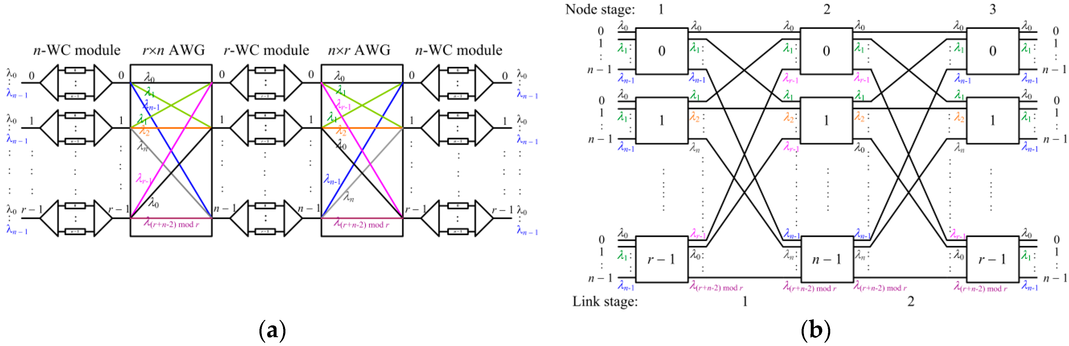
A space/wavelength nonblocking switch is shown in Figure 1a [11], which contains only two types of devices: AWGs and WCs. An N × N (N-input-port and N-output-port) AWG operates on a set of N wavelengths {λ0, λ1, …, λN−1}. Let i, o, and λw represent the input port, output port, and wavelength of a signal, respectively, wherein w ∈ {0, 1, …, N − 1}. The relationship among the three parameters of i, o, and w is specified by the equation below:
w = (i + o) mod N
Each input can transmit N signals of different wavelengths through the device without blocking. For an N × M AWG with M ≤ N, we can take the first M output ports of an N × N AWG and apply the same routing relationship as described in Equation (1). The same applies to an M × N AWG. The t-WC module in Figure 1 refers to a set of t WCs. Let ψ = {λ0, λ1, …, λt−1} be the set of input wavelengths, and Г = {λ0′, λ1′, …, λt−1′} be the set of output wavelengths. Each WC inside the t-WC module converts an input wavelength λi to an output wavelength λj′, where λi ∈ ψ and λj′ ∈ Г, respectively. Note that each WC must be tunable as the wavelength conversion is not fixed.
The switch in Figure 1a has r input links and each link carries n wavelengths. Therefore, an input (or output) channel in the switch is defined by a two tuple (link, wavelength). The switch uses three stages of WC modules: n-WC, r-WC, and n-WC modules, respectively. These WC modules are interconnected with two AWGs with the size r × n and n × r. This switch is rearrangeable nonblocking (RNB), in the sense that whenever an input channel and an output channel is available, a connection between the two can always be set up by the switch, although some existing connections may need to be re-arranged. Given a set of connections, the looping algorithm [23] is the standard routing algorithm to route all the connections through the switch.
To see why the network is rearrangeable nonblocking, we can transform the entire switch into the space domain (called the wavelength dilated switch), as shown in Figure 1b. This transformation technique is well established in the literature [11,24]. In the wavelength-dilated space topology, an n-WC (or r-WC) module is represented by an n × n (or r × r) space switch and AWGs become connecting wires in Figure 1b. The two networks are equivalent to each other. The transformed space network of Figure 1b is a three-stage C(n, n, r) Clos network [25]. This equivalent network is rearrangeable nonblocking. Consequently, its original wavelength/space network is also rearrangeable nonblocking.
However, the problem becomes complicated once we consider the actual values of t, n, and r. Note that the current maximum value of n is around 90 [26], and the current maximum value of N, the size of an AWG, is around 32 [27]. If r > N or n > N, these cases cannot be implemented. Neither can the case r > n due to the number of wavelengths limitation. To avoid the design constraints imposed by the values above, [11] presents a decomposition technique, decomposing the AWGs and WC modules recursively in the original topology. The technique is quite complicated. In the following, we describe a new decomposition technique. The decomposition is carried out in the dilated topology. Conceptually, it is much simpler than that described in [11]. Instead of decomposing the AWGs and WC modules in the original topology as done in [11], we show that it is possible to carry out the decomposition in the expanded space domain directly. This approach is simpler and more intuitive.
Note that in the wavelength dilated topology (as such Figure 1b), the node stages are numbered from 1 and the links from 0. Each output of node stage 1 can be written as a two-tuple (x1, x2), where 0 ≤ x1 ≤ r − 1, 0 ≤ x2 ≤ n − 1, where x1, called the switch field, represents the switch on which the link is located and x2, called the member field, represents the link’s number inside x1. Similarly, an input of node stage 2 can also be written as a two-tuple (y1, y2)\, where 0 ≤ y1 ≤ n − 1, 0 ≤ y2 ≤ r − 1. Similarly, y1 is the switch field and y2 the member field. In the three-stage space equivalent topology, the interconnection pattern between the first and the second node stage can be written as a mapping from the outputs of node stage 1 to the inputs of node stage 2. Given (x1, x2), the mapping can be described as:
(x1, x2) → (y1 = x2, y2 = x1)
2.2. A New Decomposition Scheme
Due to the limited size of AWGs, if r > N or n > N, the network in Figure 1 cannot be implemented. Neither can the case of r > n be implemented, because the number of wavelengths required to implement the AWGs and the middle WC module stage is not obtained. The decomposition described below can solve this problem.
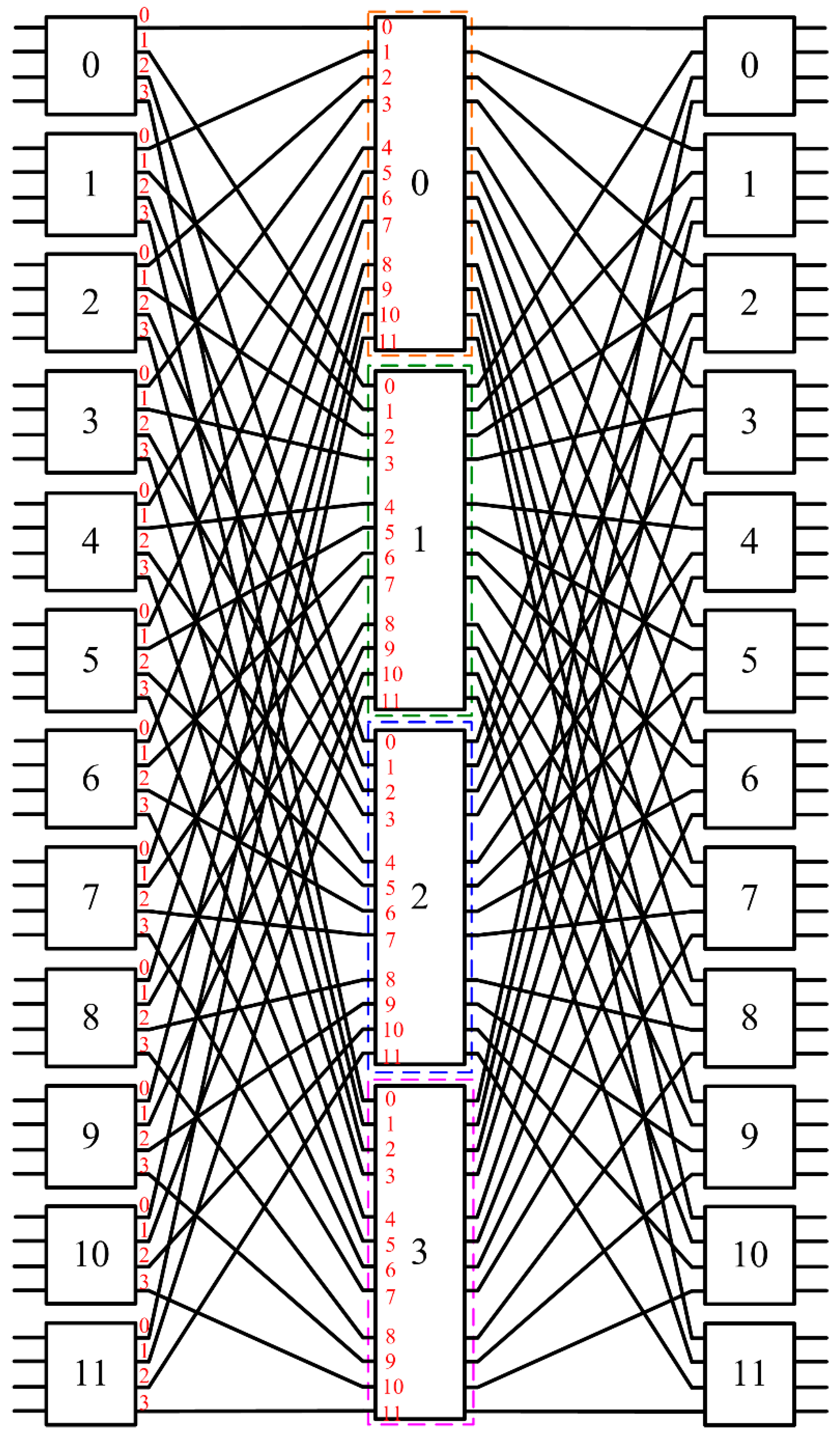
To simplify the discussion, we assume n = N in the following example. We will explain later why the method applies directly to the case n > N. Let r be a multiple of k, where k ≤ n. Suppose r = k × r1. Let us decompose an r × r switch of the middle stage in Figure 2 into a three-stage C(k, k, r1) network, as shown in Figure 3, where an example with k = 4 and r = 12 is given. Based on the Clos theory, the new wavelength dilated topology of Figure 2 is RNB, which means that its corresponding switch in the original space and wavelength domains is still an RNB network. Properties 1 and 2 given below show that the number of wavelengths and the size of AWGs required to implement the corresponding switch in the original wavelength/space domains will be reduced.
In the paper, starting from node 0, all of the k consecutive switches in node stage 1 of Figure 3 are considered a group. Let Ni be the ith node group of stage 1, where 0 ≤ i ≤ r1 − 1. That is:
Ni = {node x1 | i·k ≤ x1 ≤ (i + 1)·k − 1}.
We also consider all of the outputs (x1, x2) of switches in the same group as one output group. Let Oi be the ith output group of stage 1. That is:
Oi = {(x1, x2) | i·k ≤ x1 ≤ (i + 1)·k − 1, 0 ≤ x2 ≤ n − 1}
After decomposition, each r × r switch of stage 2 is divided into r1 sub-switches of size k × k. Let each input of the second stage switches be represented by a new two-tuple (z1, z2), where z1 represents the new switch number. Given (y1, y2), we can derive (z1, z2) as:
Furthermore, we can also divide the switches of the second stage after decomposition into r1 groups. Let Mi denote the ith node group of stage 2, where 0 ≤ i ≤ r1 − 1, and Mi is defined to be:
Mi = {node z1 | z1 ∈ {i, i + r1, …, i + (k − 1)·r1}.
Property 1.
In the dilated topology of Figure 3, all output links of Ni are connected to the input links of Mi and vice versa, where 0 ≤ i ≤ r1 − 1.
Proof.
Let Ii be the set of inputs of Mi, where 0 ≤ i ≤ r1 − 1. That is:
Ii = {(z1, z2) | z1 ∈ {i, i + r1, …, i + (k − 1)·r1}, 0 ≤ z2 ≤ k − 1}
Let (x1, x2) ∈ Oi. Then, the input of the second stage switch, which (x1, x2) is connected to, can be derived from Equations (2), (4), (5), and (7), as follows:
(x1, x2) → (z1, z2) = (x2×r1 + ⌊x1/k⌋, x1 mod k) (∵ Equations (2) and (5).)
= (x2×r1 + i, x1 mod k) (∵ Equation (4).)
∈ Ii. (∵ Equations (4) and (7).)
Similarly, we can show that if (z1, z2) ∈ Ii, it will be connected to an output (x1, x2) of the first stage switches and (x1, x2) ∈ Oi. ☐
Property 1 shows that the mapping describing the interconnection pattern between the first and the second node stages can be broken into non-overlapping mappings, meaning that they have no commonly shared links among these mappings.
Property 2.
Assume r = k × r1. After decomposing a middle stage switch into a three-stage C(k, k, r1) network (see Figure 3), the number of wavelengths required to implement the corresponding switch in the original space and wavelength domains is reduced to max{r1, n} from max{r, n}.
Proof.
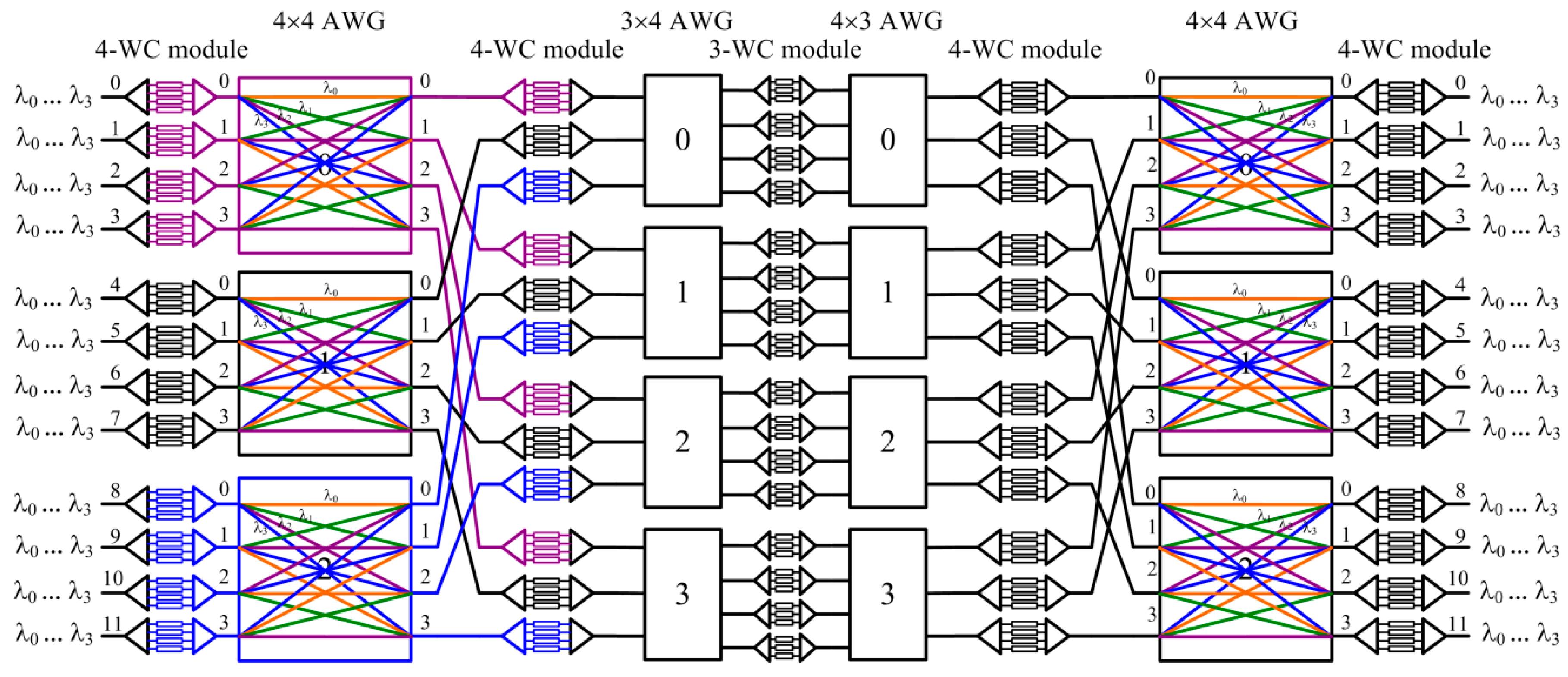
Property 1 shows that after decomposition, the mapping describing the interconnection pattern between node stage 1 and node stage 2 (see Figure 3) can be broken into r1 non-overlapping mappings. Thus, the implementation corresponding to the new dilated topology can be derived as shown in Figure 4, wherein each r-WC module in the middle stage is now broken into 2r1 k-WC modules and k r1-WC modules, the first (or second) r × n (or n × r) AWG is broken into r1 independent AWGs, and the size of each AWG is k × n (or n × k), where k ≤ n. In addition, 2n additional AWGs of size r1 × k and k × r1 are generated.
As a result, the number of wavelengths required to implement the corresponding topology in the original space and wavelength domains is reduced to max{r1, n} from max{r, n}. ☐
From the proof of Property 2, we can also see that the size of the AWGs is reduced. If r1 > n, we can then apply the same principle to further decompose r1, as described below. For a given n, let us factor r as n1 × n2 × … × ns, where ni is the largest factor of r/(n1 × n2 × … × ni−1) with 1 < ni ≤ n for 1 ≤ i ≤ s. Such factorization is called a compact factorization of r in the paper. For example, given r = 24 and n = 4, the compact factorization of r is 4 × 3 × 2. Using the method described previously, there will be 2s + 1 node stages in the final topology in the space domain. Since each stage of the space switches corresponds to a stage of WC modules in the original network, we need to minimize s. It is easy to see that under the requirement that each factor ni is the largest factor of r/(n1 × n2 × … × ni−1) with 1 < ni ≤ n, a compact factorization of r leads to the minimum number of stages.
Property 3.
The compact factorization of r is unique.
Proof.
Suppose r has two distinct compact factorizations: n1 × n2 × … × ns and n1′ × n2′ × … × ns′. Assume i is the smallest index, such that ni ≠ ni′, that is, nj = nj′ for all j ≤ i − 1. It implies that either ni or ni′ is not the largest factor of r/(n1 × n2 × … × ni−1) (= r/(n1′ × n2′ × … × ni−1′)), which contradicts the definition of compact factorization. Hence, the proof is complete. ☐
Figure 5 and Figure 6 show another example with r = 24 and n = 4. This case was not discussed in [11], which only presents the case where r is a power of n. In the example above, we assume n = N.
Let us consider the case n > N (this case was not discussed in [11] either). Consider the example where n = 8, N = 4, and r = 24 (see Figure 7). All we need to do is to demux the n wavelengths into n/N fibers and the remaining systems will be exactly the same as described in Figure 6. Note that these n wavelengths are converted to wavelengths λ0, λ1, …, λN−1 in the remaining systems. Thus, only N wavelengths are used internally in the final network (i.e., after the first stage of WC modules and before the last stage of WC modules).
From the above discussion, we can see that our decomposition technique is carried out in the space domain. As long as the network is nonblocking in the equivalent space network, the original space/wavelength network is nonblocking. This makes our decomposition simpler than the decomposition technique presented in [11], which is completed in both the space and wavelength domains. Since we only need to deal with the space domain, our technique is also more flexible in designing networks of different sizes.
3. WSS-Based Approach
Another approach to the design of RNB wavelength/space switches is based on WSSes [20,21,22]. As shown in Figure 8a, each input and output i of an r × r WSS carries n wavelengths, denoted by , for 0 ≤ i ≤ r − 1. A WSS can switch one wavelength channel from an input to any output, as long as no other signals of the same wavelength are switched to the same output (see Figure 8a). There are many technologies and architectures for implementing the device [28,29,30]. A possible implementation is shown in Figure 8b, where each block in the middle represents a nonblocking space switch. Note that a WSS requires space switching, but contains no WCs. Thus it is nonblocking in the space domain, but not in the wavelength domain.
A typical architecture for making a WSS-based wavelength/space RNB switch is shown in Figure 9a, where there are three stages of r × r WSSes and two stages of n-WC modules that perform fixed wavelength conversions and need not be tunable. Switching is done through dynamically changing the states of the space switches in the architecture. In contrast, the architecture of Section 2 contains no space switches and switching is done through dynamically changing the states of WCs.
To understand how to make a WSS-based nonblocking wavelength/space switch, we again expand the topology of the switch in the space domain [31]. Note that in the wavelength dilated topology (as such Figure 9b), node stages are numbered from 1 and links from 0. Each r × r WSS is represented by n r × r space switches in the expanded space topology, where n is the number of wavelengths carried on each input and output fiber. When WSS is expanded in the wavelength domain, all r input or output links will be repeated n times in the space domain. Let ζ2 represent the link number in the original topology, where 0 ≤ ζ2 ≤ r − 1. Then, we can use a two-tuple (ζ1, ζ2), 0 ≤ ζ1 ≤ n − 1, to represent a link in the expanded space topology, where ζ1 represents the group number of each link and each group corresponds to one wavelength in the expanded space topology. The interconnection pattern between two stages of space switches in the expanded space topology must follow the following properties.
Property 4.
Each link in the expanded space topology can be represented by a two tuple (ζ1, ζ2), as defined above. Consequently, we let (t1, t2) denote an output link of stage-i switches and (t1′, t2′) the input link of stage-(i + 1) switches in the expanded space topology, where t1 and t1′ represent the corresponding group numbers. If there is a wire connecting (t1, t2) and (t1′, t2′), then t2 = t2′.
Proof.
In the original topology, the lth output link of the stage-i WSS is always connected to the lth input link of the stage-(i + 1) WSS. Therefore, in the expanded space topology, the same property must hold. Thus, we prove the property above. ☐
Furthermore, we have the following property.
Property 5.
If there is a wire connecting (t1, t2) and (t1′, t2) in the expanded space topology, if t1 ≠ t1′, there is a WC converting the wavelength from t1 to t1′ on link t2 in the original topology.
Proof.
This is a direct result of how the expanded space topology is constructed. ☐
The basic principle for designing a WSS-based wavelength/space nonblocking switch is to find a variant of the Clos network in the expanded space domain that can satisfy Property 4. We classify our discussion into three cases: (1) n = r, (2) n < r, and (3) n > r.
Case 1.
n = r
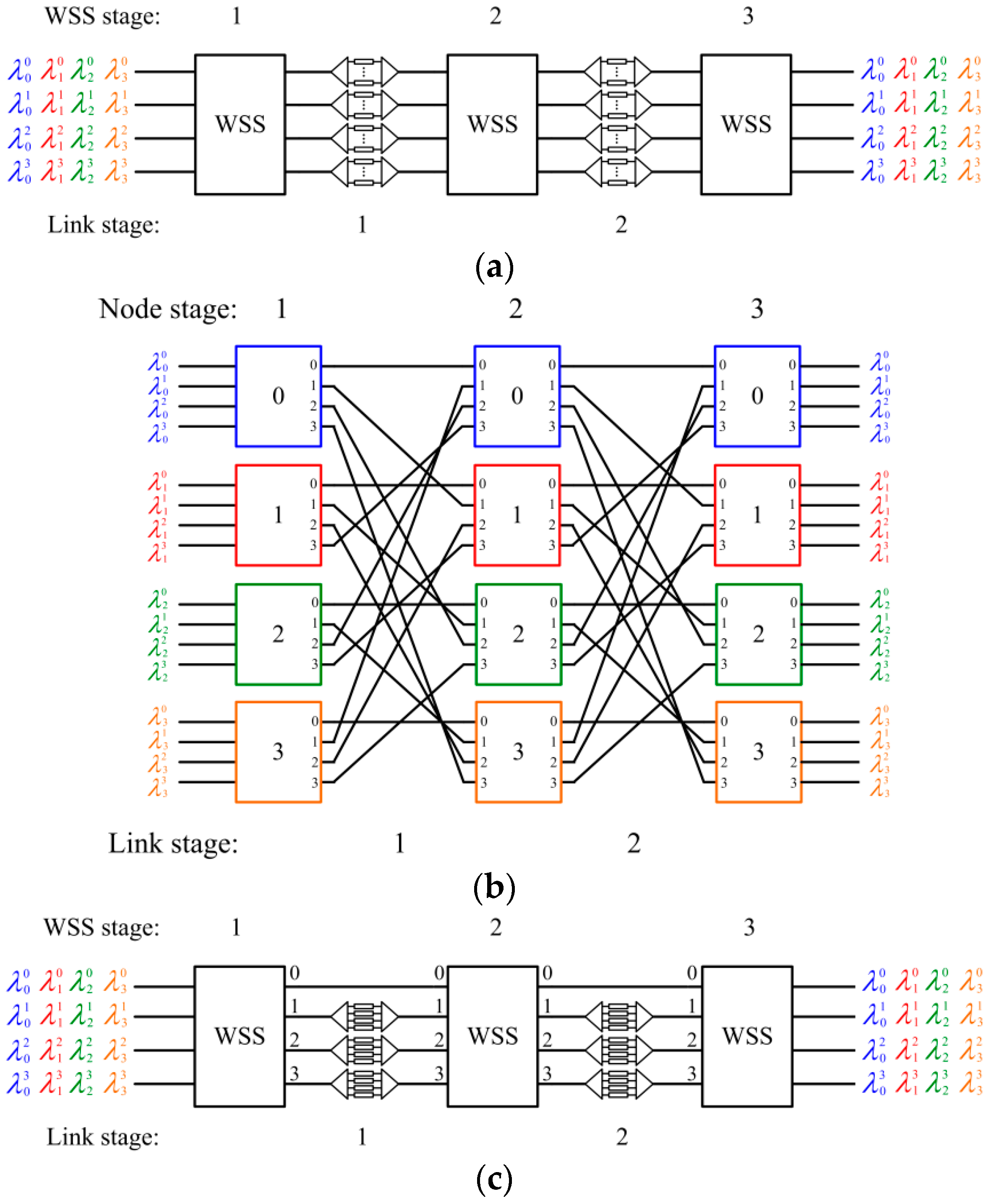
There are many variants of the Clos topology (see Figure 1b) that can satisfy Property 4. One is given in Figure 9b. For the interconnection pattern between stage-1 and stage-2 space switches, let (t1, t2) and (t1′, t2′) be defined as before. We can then describe the interconnection pattern as:
(t1, t2) → (t1′ = (t1 + t2) mod r, t2′ = t2)
The interconnection connecting stage-2 and stage-3 space switches is the mirror image of the mapping described by Equation (8). The topology of this network is given in Figure 9b. From this topology, we can derive from the original wavelength/space switch how many converters are needed on each link and what conversions will be performed by them (Property 5). The result is shown in Figure 9c.
Property 6.
The WSS-based wavelength/space switch given in Figure 9c is rearrangeably nonblocking.
Proof.
The topology of the network expanded in the space domain is shown in Figure 9b. For any permutation between the inputs and outputs to set up, we can construct a bipartite graph where each input (output) switch represents a vertex on the left (right). If there is a connection from an input switch to an output switch, an edge is added between the two corresponding vertexes in the bipartite graph. We then use graph theory to determine the chromatic number of the bipartite graph [25]. Although the interconnection pattern for the switch in Figure 9c is a variant of the Clos network, the constructed bipartite graph is exactly the same as the constructed bipartite graph for the latter (Figure 1b). Thus, the network described by the expanded space topology is RNB. This also means that the original network in Figure 9c is RNB. ☐
The example given above is for the case r = n. The approach, however, also places some constraints on r and n. In other words, not all (r, n) combinations can be implemented.
Case 2.
n < r
Under this condition, the approach can work if r is a multiple of n. To see why it is the case, we construct a variant of the Clos topology given in Figure 10a. Similarly, the interconnection pattern between two stages of space switches in the expanded space topology must follow Property 4. Let (t1, t2) and (t1′, t2′) be defined as before. The mapping (t1, t2) → (t1′, t2′) describing the interconnection pattern between stage-1 and stage-2 space switches in Figure 10a is given as:
The interconnection connecting stage-2 and stage-3 space switches is the mirror image of the mapping described by Equation (9). From the expanded topology, we can derive the original wavelength/space switch. The result is shown in Figure 10b.
Property 7.
The WSS-based wavelength/space switch given in Figure 10b is rearrangeably nonblocking.
Proof.
The proof is similar to Property 6. ☐
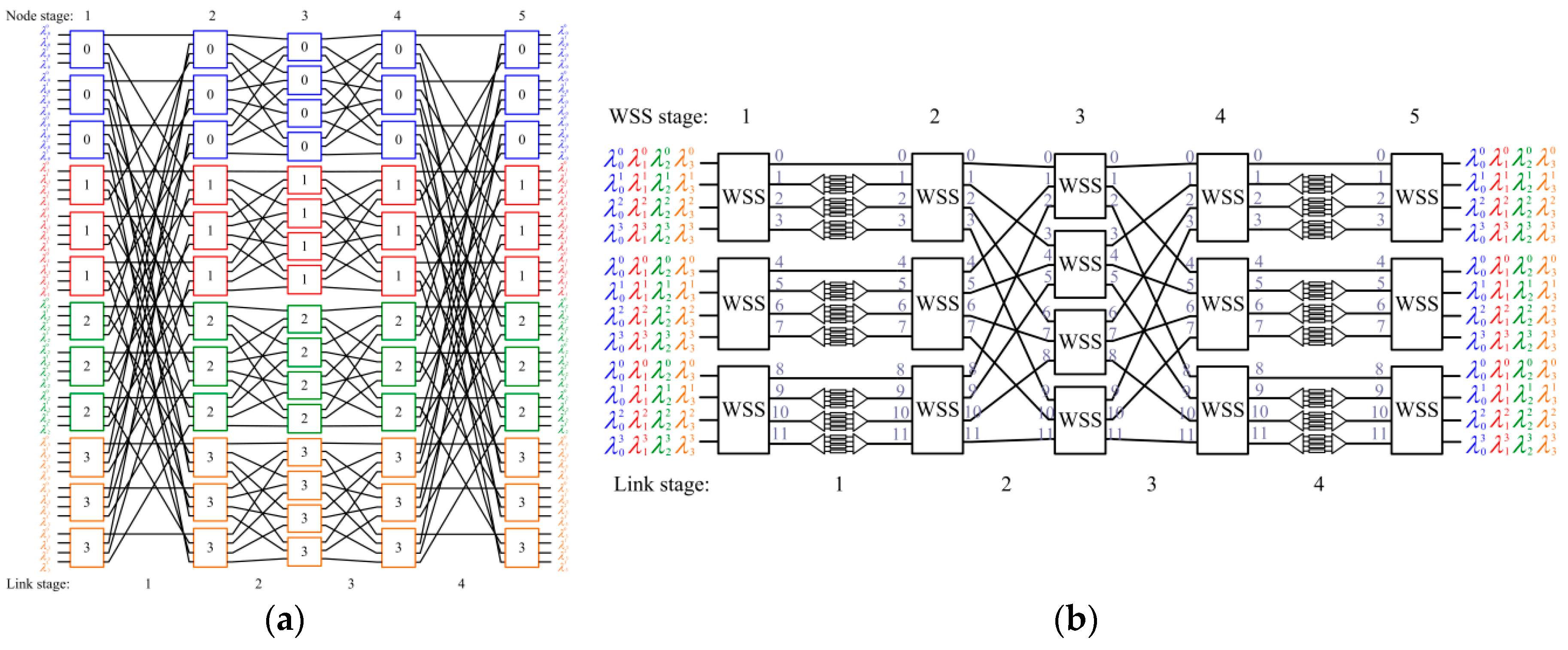
Furthermore, we also consider the case where the maximum size of each WSS switch is limited to N. Under this condition, the approach can work if r is a multiple of n2. According to the decomposition method proposed in Section 2, we construct a variant of a three-stage Clos network that can satisfy Property 4 in the expanded space topology. One is given in Figure 11a. Note that the topology shown in Figure 11a is equivalent to that in Figure 3, where switches labeled 0 in the first and last stages in Figure 11a correspond to switches 0, 4, and 8 in Figure 3. For the interconnection pattern between stage-1 and stage-2 space switches, let (t1, t2) and (t1′, t2′) be defined as before. We can then describe the interconnection pattern as:
(t1, t2) → (t1′ = (t1 + (t2 mod r)) mod r, t2′ = t2)
The interconnection connecting the last and the second last space switches is the mirror image of the mapping described by Equation (10). In addition, the network from node stage-2 to node stage-(n − 1) is divided into n r × r 3-stage Clos networks derived by the decomposition method proposed in Section 2. The topology of this network is given in Figure 11a. From this topology, we can derive from the original wavelength/space switch how many converters are needed on each link and what conversions will be performed by them (Property 5). The result is shown in Figure 11b. Similar to Property 6, the WSS-based wavelength/space switch given in Figure 10b is rearrangeably nonblocking.
It is worth noting that a k-nary Benes network is a special case under this condition, where each WSS switch is with r = k, n = k. A WSS-based 3-nary Benes network is given in Figure 12.
Case 3.
n > r
Under this condition, the approach can work if n = rk for any positive integer k. We again use the rule described by Property 4 to construct a variant of a three-stage C(r, r, n) network in the expanded space topology, as shown in Figure 11a. Let (t1, t2) and (t1′, t2′) be defined as before. The mapping (t1, t2) → (t1′, t2′) describing the interconnection pattern between stage-1 and stage-2 space switches in Figure 11a is given as:
The interconnection connecting stage-2 and stage-3 space switches is the mirror image of the mapping described by Equation (11). Again, we can use the Clos theory to prove that the switch in Figure 13a is an RNB switch. We then decompose each of the middle-stage switches into another three-stage switch. This decomposition process continues until all switches have the size of r × r. Each decomposition does not change the nonblocking property of the switch. The final result is that there will be n r × r switches in each stage and each corresponds to one wavelength in the expanded space topology. Since the overall switch is RNB, the original network is RNB.
4. Space-Wavelength Tradeoffs
4.1. Switch Size Constraint
We first compare the constraints of these methods on the switch sizes. For given n and N, the explicit formula for allowed r is shown below.
- AWG-based approach presented in this paper:The value of r can be any of k1 × k2 × … × ks for ki ∈ {1, 2, …, N}, 1 ≤ i ≤ s.
- WSS-based approach:The value of r can be any of nk and n1/k (provided r is a power of n) for any positive integer k.
Two examples are given below.
Case 1.
We choose n = 90 and N = 32.
As mentioned previously, the current largest commercially available AWG is 32 × 32 [27]. Thus, we select N = 32.
- 1.
- AWG-based approach presented in this paper:r can be any of {1, 2, …, 8, …, 32, 33, 34, 35, …, 63, 64, 65, …}.
- 2.
- WSS-based approach:r = 90 k for any positive integer k.
Case 2.
We choose n = 64 and N = 32.
Possible switch sizes are listed below.
- 1.
- AWG-based approach presented in the paper:r can be any of {1, 2, …, 8, …, 32, 33, 34, 35, …, 63, 64, 65, …}.
- 2.
- WSS-based approach:The value of r can be any of 2, 4, 8, 64 k for any positive integer k.
Comparing the AWG-based and the WSS-based approaches, we can see that the former is more flexible in this regard.
4.2. Hardware Complexity
We compare the number of WCs, AWGs, and space switches required in the AWG-based and the WSS-based architectures. Among them, WCs are perhaps the most costly. Assume n, r, and N are given, the exact formula for the number of WCs required can be derived as follows.
- AWG-based approach presented in this paper:In the decomposed topology, there are 2s + 1 stages of WC modules, and each stage has nr WCs, where r can be any of k1 × k2 × … × ks for ki ∈ {1, 2, 3, …, N}, 1 ≤ i ≤ s. In total, the number of WCs is (2s + 1)·nr.
- WSS-based approach with n < r:In the topology, there are r/n WSSes of size n × n in the middle stage, and each such n × n WSS uses 2·(n − 1) WC modules of size n × n, where each n × n WC module uses n WCs. In total, the number of WCs is (r/n)·2·(n − 1)·n = 2r·(n − 1).
- WSS-based approach with n ≥ r:In the topology, there are 2·(logr n) stages of WC modules, and each stage has (r − 1) WC modules of size n × n, where each n × n WC module uses n WCs. In total, the number of WCs is 2·(logr n)·(r − 1)·n.
We select a switch configuration that can be constructed by both approaches. Table 1 tabulates the results for the case of n = 64, r = 64, and N = 32. Under this case, the AWG-based approach requires five stages to construct and it requires many more WCs than the WSS-based approach. Note that the number of space switches required in the WSS-based approach is based on the implementation shown in Figure 8. The number of WCs required, however, is not affected by the technologies used to implement the WSS.
Table 2 tabulates the results for the case of n = 64, r = 8, and N = 32. In this case, the selected r is much smaller. Under this condition, the AWG-based approach will perform much better, in terms of the WCs required. This is because the number of stages needed in the AWG-based architecture is only three. However, the WSS-based approach requires more stages to be implemented.
5. Conclusions
In this paper, we showed a new way of designing an AWG-based nonblocking wavelength/space switch. The new method is a generalization of that given in [11], but simpler and more flexible in terms of the construction of different switch sizes. It is based on a decomposition carried out in the transformed space-domain only topology. Not only is the new decomposition simpler, it is also easy to see how different (space, wavelength) combinations can be achieved with this decomposition technique. We also studied another class of wavelength/space switches which are based on WSSes (wavelength selective switches) and compared the two approaches in terms of tradeoffs between the number of WCs and the amount of optical space switching required. The new decomposition technique, we believe, can be applied to other AWG-based switching systems in the future.
Acknowledgments
Lin’s research is supported by the Ministry of Science and Technology, Taiwan, under Contract MOST 105-2221-E-024-002. Lea’s research is supported by Hong Kong RGC Grant 16206015.
Author Contributions
Architecture design was done by both Bey-Chi Lin and Chin-Tau Lea. Data analysis was mostly done by Bey-Chin Lin. Both Bey-Chi Lin and Chin-Tau Lea participated in the writing of the paper.
Conflicts of Interest
The authors declare no conflict of interest.
References
- Salsi, M.; Koebele, C.; Tran, P.; Mardoyan, H.; Dutisseuil, E.; Renaudier, J.; Bigot-Astruc, M.; Provost, L.; Richard, S.; Sillard, P.; et al. Transmission of 96 × 100 Gb/s with 23% super-FEC overhead over 11,680 km, using optical spectral engineering. In Proceedings of the Optical Fiber Communication Conference and Exposition and the National Fiber Optic Engineers Conference, Los Angeles, CA, USA, 6–10 March 2011. [Google Scholar]
- Okamoto, S.; Watanabe, A.; Sato, K.-I. Optical path cross-connect node architectures for photonic transport network. J. Lightwave Technol. 1996, 14, 1410–1422. [Google Scholar] [CrossRef]
- Iannone, E.; Sabella, R. Optical path technologies: A comparison among different cross-connect architectures. J. Lightwave Technol. 1996, 14, 2184–2196. [Google Scholar] [CrossRef]
- Marom, D.M.; Blau, M. Switching Solutions for WDM-SDM Optical Networks. IEEE Commun. Mag. 2015, 53, 60–68. [Google Scholar] [CrossRef]
- Khodashenas, P.S.; Rivas-Moscoso, J.M.; Siracusa, D.; Pederzolli, F.; Shariati, B.; Klonidis, D.; Salvadori, E.; Tomkos, I. Comparison of Spectral and Spatial Super-channel Allocation Schemes for SDM Networks. J. Lightwave Technol. 2016, 34, 2710–2716. [Google Scholar] [CrossRef]
- Wilfong, G.; Mikkelsen, B.; Doerr, C.; Zirngibl, M. WDM crossconnect architectures with reduced complexity. J. Lightwave Technol. 1999, 17, 1732–1741. [Google Scholar] [CrossRef]
- Cheyns, J.; Develder, C.; Breusegem, E.V.; Colle, D.; Turck, F.D.; Lagasse, P.; Pickavet, M.; Demeester, P. Clos lives on in optical packet switching. IEEE Commun. Mag. 2004, 42, 114–120. [Google Scholar] [CrossRef]
- Pattavina, A.; Zanzottera, R. Non-blocking WDM switches based on arrayed waveguide grating and shared wavelength conversion. In Proceedings of the IEEE 25th Conference on Computer Communications (INFOCOM), Barcelona, Spain, 23–29 April 2006. [Google Scholar]
- Ngo, H.Q.; Pan, D.; Qiao, C. Constructions and analyses of nonblocking WDM switches based on arrayed waveguide grating and limited wavelength conversion. IEEE Trans. Netw. 2006, 14, 205–217. [Google Scholar] [CrossRef]
- Zanzottera, R.; Matrakidis, C.; Stavdas, A.; Sygletos, S.; Pattavina, A. Design of OXC architectures based on arrayed waveguide gratings: Topological properties and physical performance. In Proceedings of the IEEE Workshop on High Performance Switching and Routing (HPSR), Poznan, Poland, 7–9 June 2006. [Google Scholar]
- Ye, T.; Lee, T.T.; Hu, W. AWG-Based Non-Blocking Clos Networks. IEEE Trans. Netw. 2015, 23, 491–504. [Google Scholar] [CrossRef]
- Ye, T.; Lee, T.T.; Hu, W. A study of modular AWGs for large-scale optical switching systems. J. Lightwave Technol. 2012, 30, 2125–2133. [Google Scholar] [CrossRef]
- Eramo, V. Comparison in Power Consumption of Synchronous and Asynchronous Optical Packet Switches. J. Lightwave Technol. 2010, 28, 847–857. [Google Scholar] [CrossRef]
- Eramo, V.; Listanti, M. Power Consumption in Bufferless Optical Packet Switches in SOA Technology. J. Commun. Netw. 2009, 1, B15–B29. [Google Scholar] [CrossRef]
- Eramo, V.; Germoni, A.; Raffaelli, C.; Savi, M. Multi-Fiber Shared-Per-Wavelength All-Optical Switching: Architecture, Control and Performance. J. Lightwave Technol. 2008, 26, 537–551. [Google Scholar] [CrossRef]
- Ramamirtham, J.; Turner, J.S. Design of wavelength converting switches for optical burst switching. In Proceedings of the International Twenty-First Annual Joint Conference of the IEEE Computer and Communications Societies (IEEE INFOCOM), New York, NY, USA, 23–27 June 2002. [Google Scholar]
- Cheyns, J.; Develder, C.; Brusegem, E.V.; Ackaert, A.; Pickavet, M.; Demeester, P. Routing in an AWG-based optical packet switch. Photonic Netw. Commun. 2003, 5, 69–80. [Google Scholar] [CrossRef]
- Bregni, S.; Pattavina, A.; Vegetti, G. Architectures and performance of AWG-based optical switching nodes for IP networks. IEEE J. Sel. Areas Commun. 2003, 21, 1113–1121. [Google Scholar] [CrossRef]
- Maier, M.; Reisslein, M. AWG-based metro WDM networking. IEEE Commun. Mag. 2004, 42, S19–S26. [Google Scholar] [CrossRef]
- Ishii, Y.; Wakamiya, M.; Kanagawa, A.; Hadama, K.; Yamaguchi, J.; Kawajiri, Y. MEMS-based 1 × 43 wavelength-selective switch with flat passband. In Proceedings of the European Conference on Optical Communication (ECOC), Vienna, Austria, 20–24 September 2009. [Google Scholar]
- Ishii, Y.; Oba, N.; Sahara, A.; Hadam, K. WSS Module Technology for Advanced ROADM. NTT Tech. Rev. 2014, 12, 1–5. [Google Scholar]
- Wang, Z.; Chen, W.; Zhu, Z.; Chen, Y.J. Design of wavelength-selective switch using micro-ring resonators. In Proceedings of the International Pragmatics Conference (IPrA), Riva del Garda, Italy, 10–15 July 2005. [Google Scholar]
- Benes, V.E. Mathematical Theory of Connecting Networks and Telephone Traffic; Academic: New York, NY, USA, 1965. [Google Scholar]
- Hunter, D.K.; Smith, D.G. New architectures for optical TDM switching. J. Lightwave Technol. 1993, 11, 495–511. [Google Scholar] [CrossRef]
- Clos, C. A study of nonblocking switching networks. Bell Syst. Technol. J. 1953, 32, 406–424. [Google Scholar] [CrossRef]
- Niwa, T.; Hasegawa, H.; Sato, K.I.; Watanabe, T.; Takahashi, H. Large port count wavelength routing optical switch consisting of cascaded small-size cyclic arrayed waveguide gratings. IEEE Photonics Technol. Lett. 2012, 24, 2027–2030. [Google Scholar] [CrossRef]
- Arrayed Waveguide Gratings. Available online: http://www.enablence.com/ (accessed on 1 December 2013).
- Ranalli, A.R.; Scott, B.A.; Kondis, J.P. Liquid crystal-based wavelength-selective cross connect. In Proceedings of the 25th European Conference on Optical Communication (ECOC), Nice, France, 26–30 September 1999. [Google Scholar]
- Ford, J.E.; Aksyuk, V.A.; Bishop, D.J.; Walker, J.A. Wavelength add-drop switching using tilting micromirrors. J. Lightwave Technol. 1999, 17, 904–911. [Google Scholar] [CrossRef]
- Doerr, C.R.; Stulz, L.W.; Gates, J.; Cappuzzo, M.; Laskowski, E.; Gomez, L.; Paunescu, A.; White, A.; Narayanan, C. Arrayed waveguide lens wavelength add-drop in silica. IEEE Photonics Technol. Lett. 1999, 11, 557–559. [Google Scholar] [CrossRef]
- Antoniades, N.; Yoo, S.J.B.; Bala, K.; Ellinas, G.; Stern, T.E. An architecture for a wavelength-interchanging cross-connect utilizing parametric wavelength converters. J. Lightwave Technol. 1999, 17, 1113–1125. [Google Scholar] [CrossRef]
Figure 1.
(a) An n-wavelength r × r rearrangeable nonblocking (RNB) switch with r > n. (b) Topological transformation in the space domain—a 3-stage C(n, n, r) network.
Figure 1.
(a) An n-wavelength r × r rearrangeable nonblocking (RNB) switch with r > n. (b) Topological transformation in the space domain—a 3-stage C(n, n, r) network.

Figure 2.
A three-stage C (4, 4, 12) network.

Figure 3.
Each middle switch of the second stage in Figure 2 is divided into a three-stage C(4, 4, 3) network. The mapping between the first and the second stage can be divided into three non-overlapping mappings (in purple, black, and blue, respectively).
Figure 3.
Each middle switch of the second stage in Figure 2 is divided into a three-stage C(4, 4, 3) network. The mapping between the first and the second stage can be divided into three non-overlapping mappings (in purple, black, and blue, respectively).
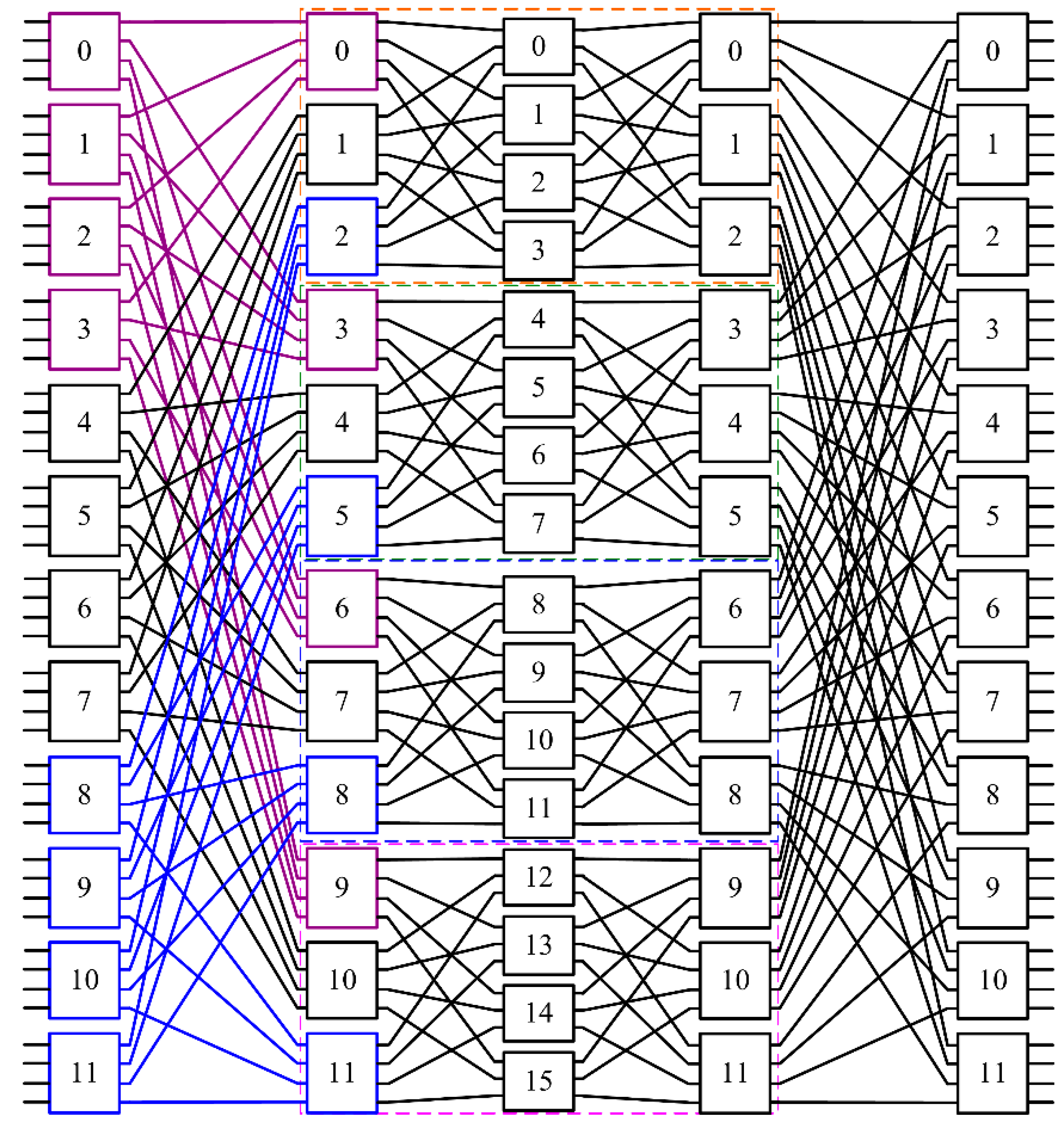
Figure 4.
An implementation of Figure 3 in the original space and wavelength domains. The arrayed-waveguide grating (AWGs) and wavelength converters (WC) modules marked in color are transformed from the components of the same color in Figure 3.

Figure 5.
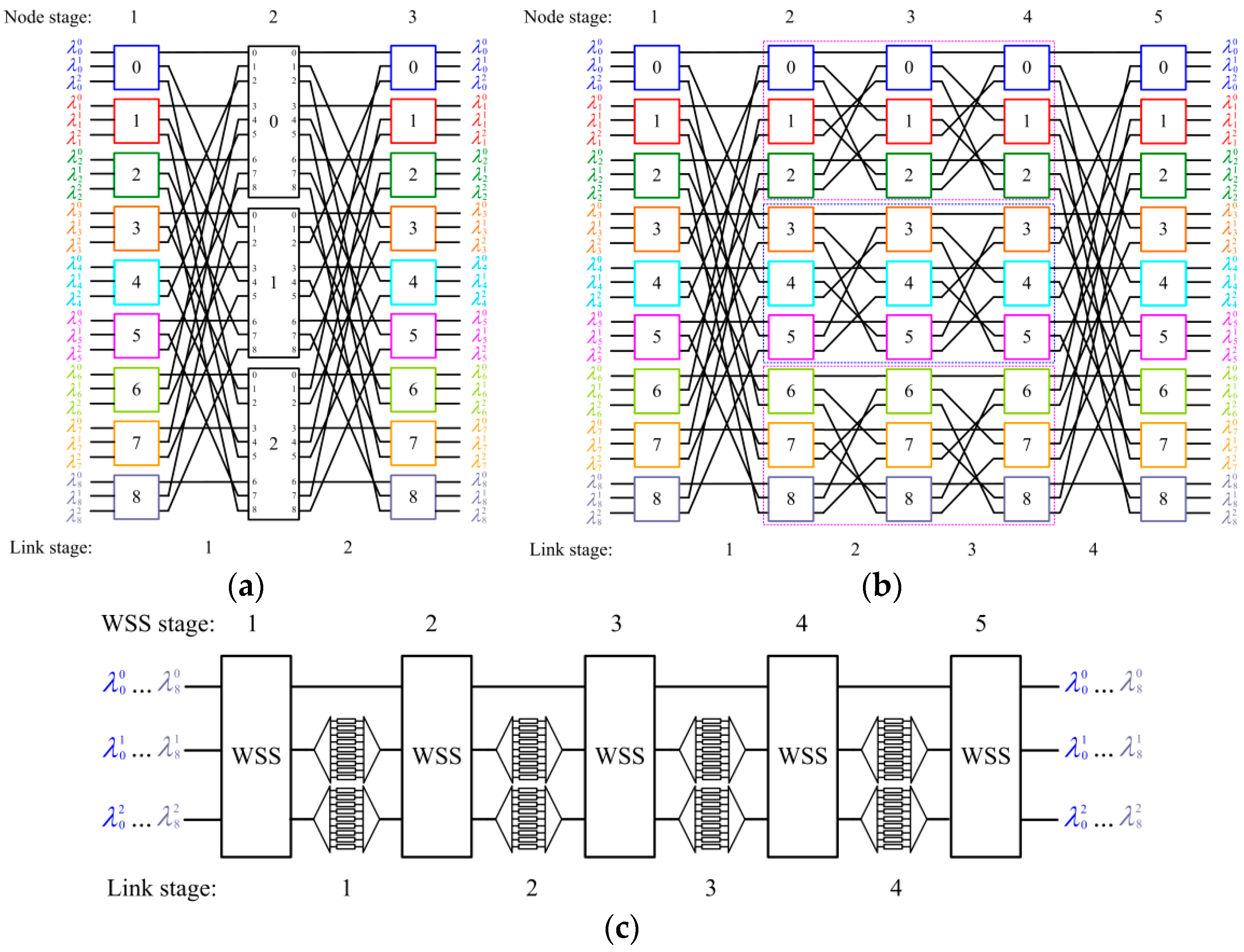
Assume r = 24, n = 4. The compact factorization of r is 4 × 3 × 2. (a) A three-stage C (4, 4, 24) network. (b) Each 24 × 24 middle switch in (a) is replaced with a multi-stage network generated by the decomposition scheme.
Figure 5.
Assume r = 24, n = 4. The compact factorization of r is 4 × 3 × 2. (a) A three-stage C (4, 4, 24) network. (b) Each 24 × 24 middle switch in (a) is replaced with a multi-stage network generated by the decomposition scheme.
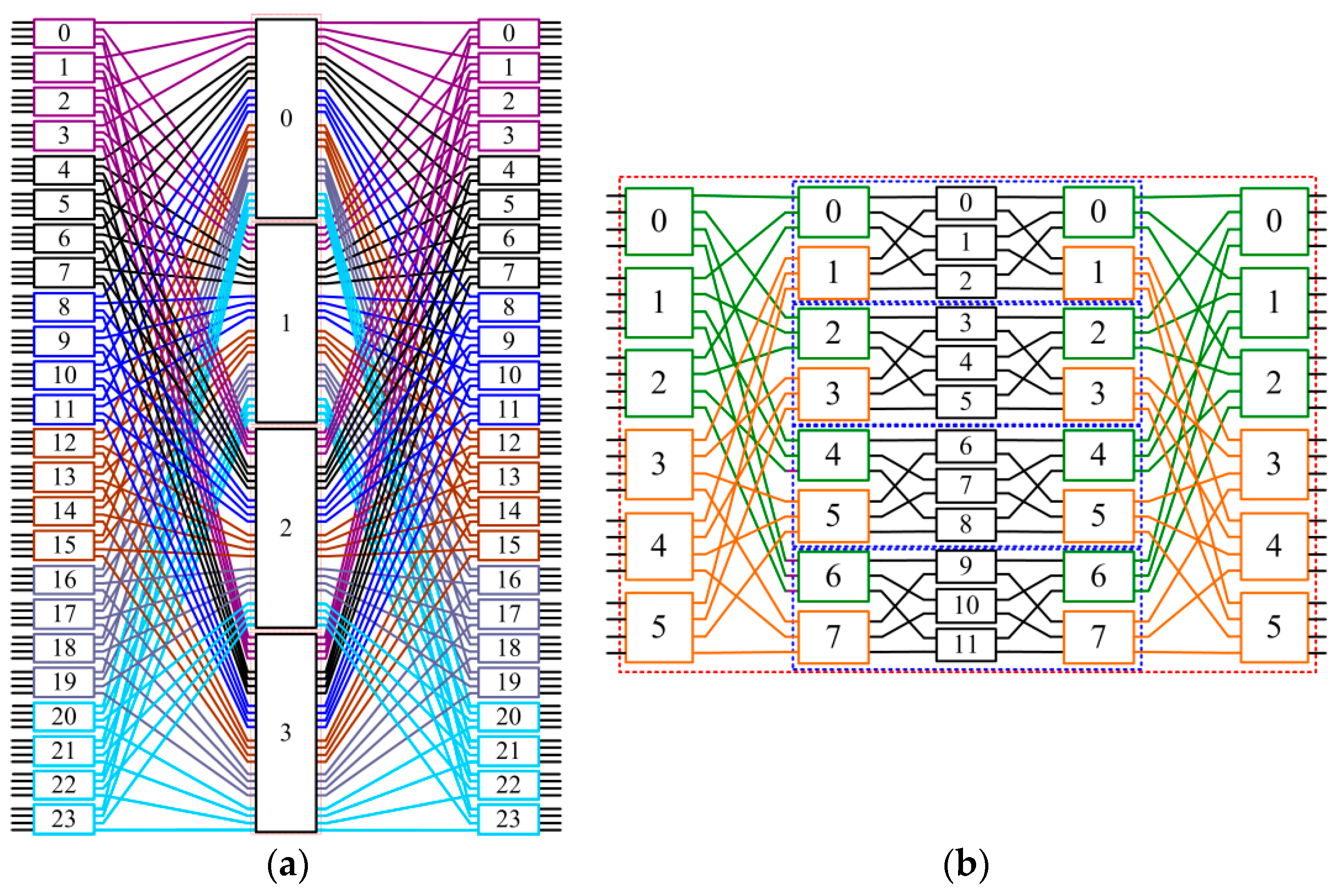
Figure 6.
An RNB network with r = 24, n = 4. Its transformed space switch is shown in Figure 5. The AWGs and WC modules marked in color are transformed from the components of the same color in Figure 5.
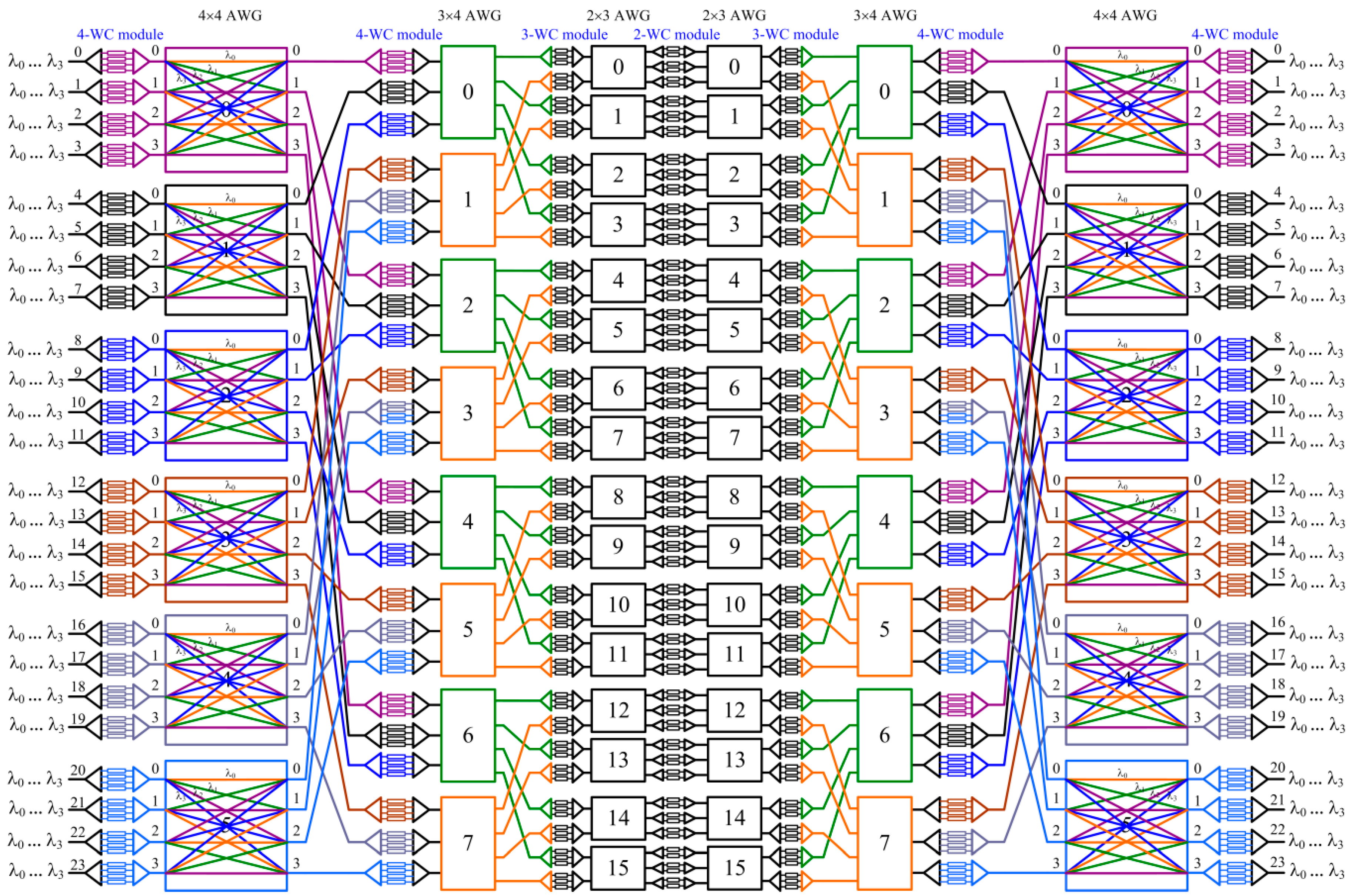
Figure 7.
An RNB network with n = 8, N = 4, and r = 24. We can just demux the eight wavelengths into two fibers and use the same technique shown in Figure 6 to design an RNB switch with such parameters. Note that these eight wavelengths are converted to wavelengths λ0, λ1, λ2, and λ3 in each middle switch.
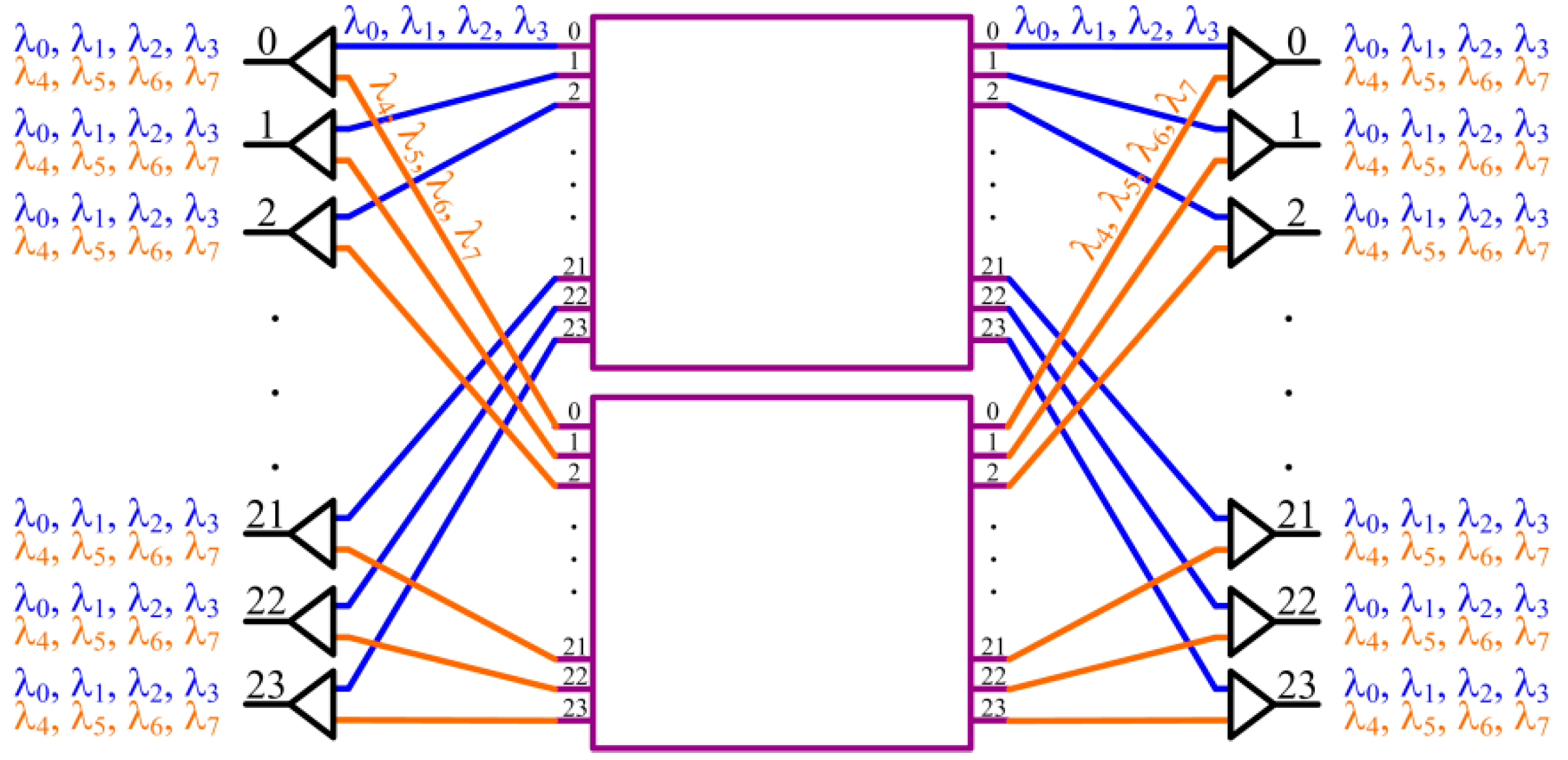
Figure 8.
(a) A 4 × 4 WSS with four wavelengths. (b) One implementation of wavelength selective switches (WSS). Each block in the middle is a nonblocking space switch.
Figure 8.
(a) A 4 × 4 WSS with four wavelengths. (b) One implementation of wavelength selective switches (WSS). Each block in the middle is a nonblocking space switch.
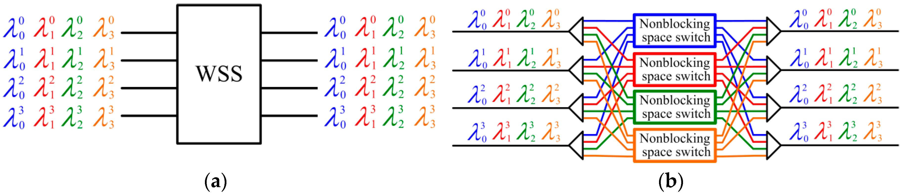
Figure 9.
(a) The general architecture of a WSS-based wavelength/space switch with r = 4, n = 4. (b) An RNB network dilated in space domain of Figure 9a. (c) From the mapping in Figure 9b, we can derive the final implementation with r = 4, n = 4.

Figure 10.
(a) An RNB network dilated in space domain with r = 12, n = 3. Note colors used for switches correspond to wavelengths λ0, λ1, and λ2. (b) The WSS-based implementation with r = 12, n = 3.
Figure 10.
(a) An RNB network dilated in space domain with r = 12, n = 3. Note colors used for switches correspond to wavelengths λ0, λ1, and λ2. (b) The WSS-based implementation with r = 12, n = 3.
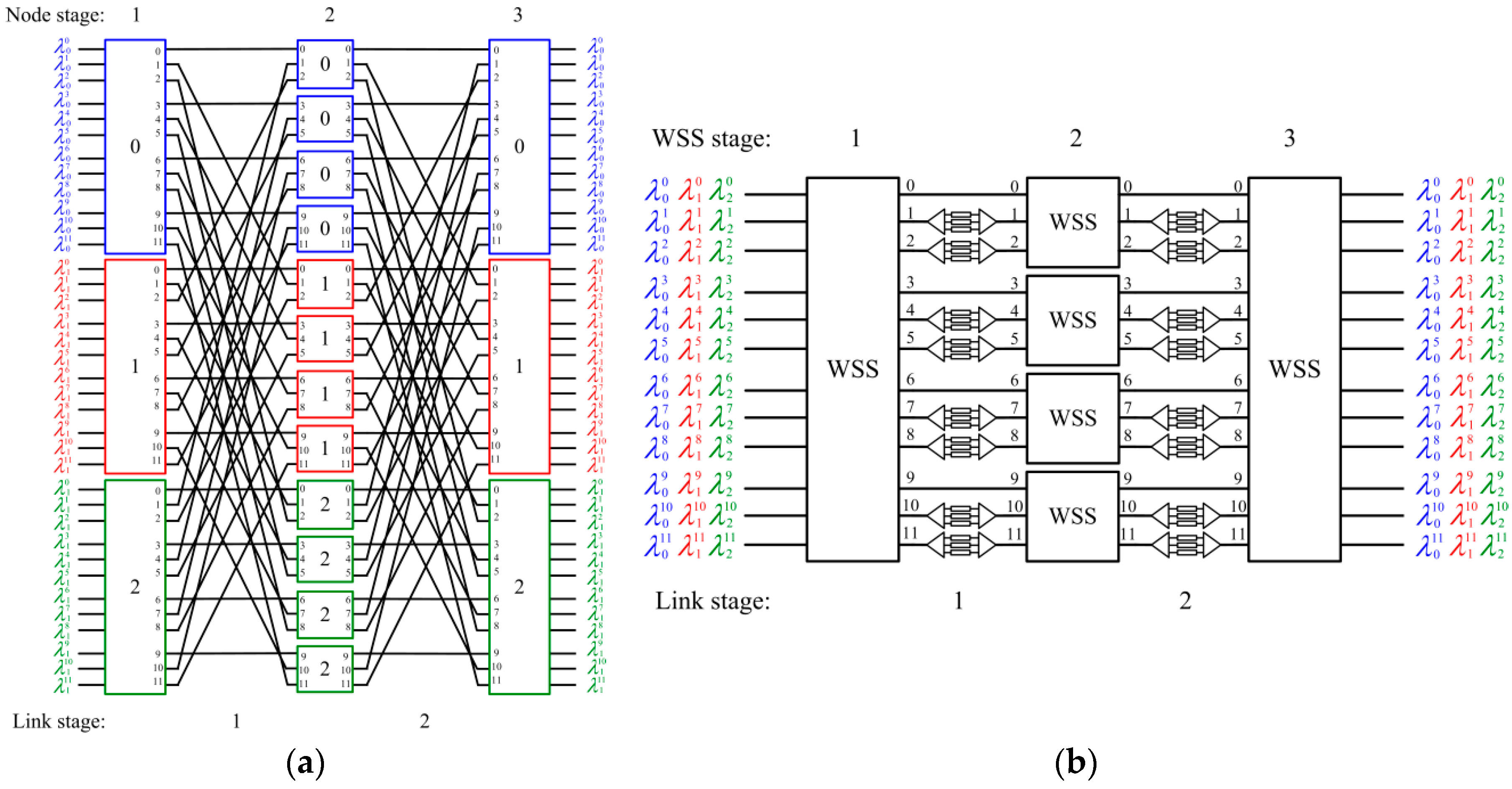
Figure 11.
A WSS-based implementation with r = 12, n = 4, where each WSS switch is with r = 4 or 3, n = 4. (a) Construct a variant of a three-stage C (4, 4, 12) network in the expanded space topology. (b) The final architecture can be derived from (a).
Figure 11.
A WSS-based implementation with r = 12, n = 4, where each WSS switch is with r = 4 or 3, n = 4. (a) Construct a variant of a three-stage C (4, 4, 12) network in the expanded space topology. (b) The final architecture can be derived from (a).

Figure 12.
A WSS-based implementation with r = 9, n = 3, where each WSS switch is with r = 3, n = 3. (a) Construct a variant of a 3-nary Benes network in the expanded space topology. (b) The final architecture can be derived from (a).
Figure 12.
A WSS-based implementation with r = 9, n = 3, where each WSS switch is with r = 3, n = 3. (a) Construct a variant of a 3-nary Benes network in the expanded space topology. (b) The final architecture can be derived from (a).
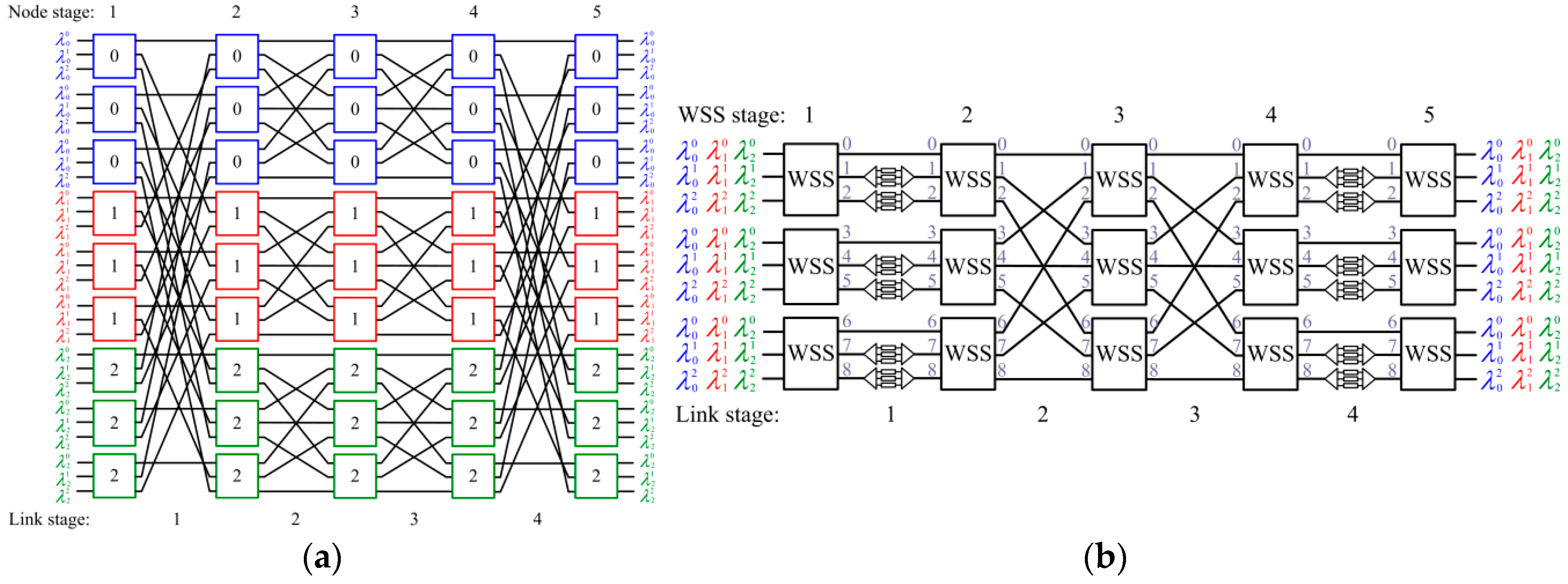
Figure 13.
A WSS-based implementation with r = 3, n = 9. (a) Construct a variant of a three-stage C (3, 3, 9) network in the expanded space topology. (b) Decompose each 9 × 9 (= n × n) middle switch further into three stages. (c) The final architecture can be derived from (b).
Figure 13.
A WSS-based implementation with r = 3, n = 9. (a) Construct a variant of a three-stage C (3, 3, 9) network in the expanded space topology. (b) Decompose each 9 × 9 (= n × n) middle switch further into three stages. (c) The final architecture can be derived from (b).


Table 1.
Comparison of the AWG-based approach and WSS-based approach with n = 64, r = 64, N = 32.
| n = 64, r = 64, N = 32 | AWG-Based Approach | WSS-Based Approach |
|---|---|---|
| Number of WCs | 24,576 | 8064 |
| Number of 32 × 32 AWGs | 8 | 0 |
| Number of 32 × 4 AWGs | 32 | 0 |
| Number of 4 × 32 AWGs | 32 | 0 |
| Number of 64 × 64 space switches | 0 | 192 |
Table 2.
Comparison of the AWG-based approach and WSS-based approach with n = 64, r = 8, N = 32.
| n = 64, r = 8, N = 32 | AWG-Based Approach | WSS-Based Approach |
|---|---|---|
| Number of WCs | 1536 | 1792 |
| Number of 16 × 32 AWGs | 1 | 0 |
| Number of 32 × 16 AWGs | 1 | 0 |
| Number of 8 × 8 space switches | 0 | 320 |
© 2017 by the authors. Licensee MDPI, Basel, Switzerland. This article is an open access article distributed under the terms and conditions of the Creative Commons Attribution (CC BY) license (http://creativecommons.org/licenses/by/4.0/).
Share and Cite
MDPI and ACS Style
Lin, B.-C.; Lea, C.-T. Construction of Nonblocking Wavelength/Space Switches with AWGs and WSSes. Appl. Sci. 2017, 7, 555. https://doi.org/10.3390/app7060555
AMA Style
Lin B-C, Lea C-T. Construction of Nonblocking Wavelength/Space Switches with AWGs and WSSes. Applied Sciences. 2017; 7(6):555. https://doi.org/10.3390/app7060555
Chicago/Turabian StyleLin, Bey-Chi, and Chin-Tau Lea. 2017. "Construction of Nonblocking Wavelength/Space Switches with AWGs and WSSes" Applied Sciences 7, no. 6: 555. https://doi.org/10.3390/app7060555
Note that from the first issue of 2016, this journal uses article numbers instead of page numbers. See further details here.