
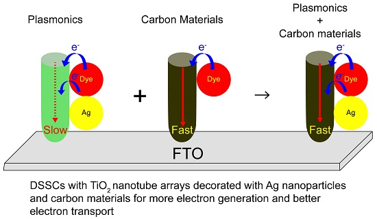
Dual Functionalized Freestanding TiO2 Nanotube Arrays Coated with Ag Nanoparticles and Carbon Materials for Dye-Sensitized Solar Cells


Abstract
:
1. Introduction
2. Materials and Methods
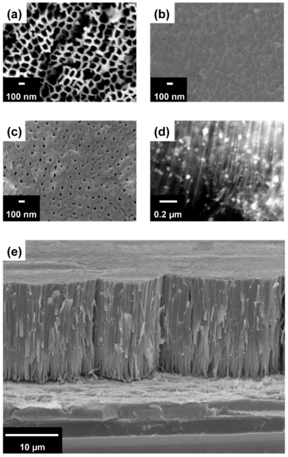
2.1. Preparation of Closed- and Open-Ended TiO2 NTAs
2.2. Preparation of Photoanodes for DSSCs Based on the TiO2 NTAs
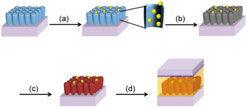
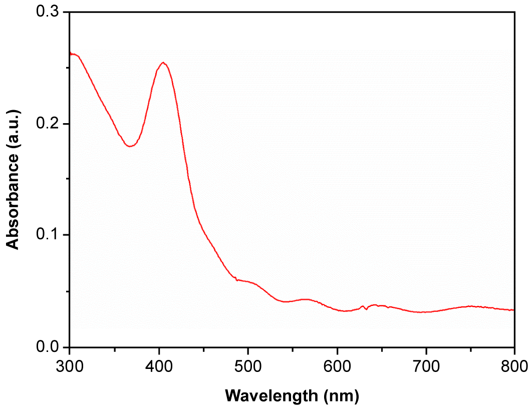
2.3. Synthesis of Ag NPs on the TiO2 NTAs by UV Irradiation
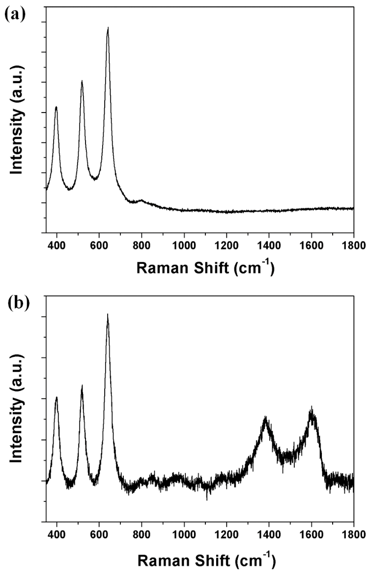
2.4. Synthesis of Carbon Materials on the TiO2 NTAs by CVD
2.5. Fabrication of Dye-Sensitized Solar Cells
2.6. Characterization of Dye-Sensitized Solar Cells
3. Results and Discussion
4. Conclusions
Supplementary Materials
Acknowledgments
Author Contributions
Conflicts of Interest
References
- Oregan, B.; Grätzel, M. A low-cost, high-efficiency solar cell based on dye-sensitized colloidal TiO2 films. Nature 1991, 353, 737–740. [Google Scholar] [CrossRef]
- Grätzel, M.J. Dye-sensitized solar cells. Photochem. Photobiol. C Photochem. Rev. 2003, 4, 145–153. [Google Scholar] [CrossRef]
- Hardin, B.E.; Snaith, H.J.; McGehee, M.D. The renaissance of dye-sensitized solar cells. Nat. Photonics 2012, 6, 162–169. [Google Scholar] [CrossRef]
- Sang, L.; Zhao, Y.; Burda, C. TiO2 Nanoparticles as functional building blocks. Chem. Rev. 2014, 114, 9283–9318. [Google Scholar] [CrossRef] [PubMed]
- Hara, K.; Sato, T.; Katoh, R.; Furube, A.; Ohga, Y.; Shinpo, A.; Suga, S.; Sayama, K.; Sugihara, H.; Arakawa, H. Molecular design of coumarin dyes for efficient dye-sensitized solar cells. J. Phys. Chem. B 2003, 107, 597–606. [Google Scholar] [CrossRef]
- Galoppini, E. Linkers for anchoring sensitizers to semiconductor nanoparticles. Coord. Chem. Rev. 2004, 248, 1283–1297. [Google Scholar] [CrossRef]
- Nazeeruddin, M.K.; Pechy, P.; Renouard, T.; Zakeeruddin, S.M.; Humphry-Baker, R.; Comte, P.; Liska, P.; Cevey, L.; Costa, E.; Shklover, V.; et al. Engineering of efficient panchromatic sensitizers for nanocrystalline TiO2-based solar cells. J. Am. Chem. Soc. 2001, 123, 1613–1624. [Google Scholar] [CrossRef] [PubMed]
- Grätzel, M. Photoelectrochemical cells. Nature 2001, 414, 338–344. [Google Scholar] [CrossRef] [PubMed]
- Katoh, R.; Furube, A.; Yoshihara, T.; Hara, K.; Fujihashi, G.; Takano, S.; Murata, S.; Arakawa, H.; Tachiya, M. Efficiencies of electron injection from excited N3 into nanocrystalline semiconductor (ZrO2, TiO2, ZnO, Nb2O5, SnO2, In2O3) films. J. Phys. Chem. B 2004, 108, 4818–4822. [Google Scholar] [CrossRef]
- Du, L.; Furube, A.; Yamamoto, K.; Hara, K.; Katoh, R.; Tachiya, M. Plasmon-induced charge separation and recombination dynamics in gold–TiO2 nanoparticle systems: Dependence on TiO2 particle size. J. Phys. Chem. C 2009, 113, 6454–6462. [Google Scholar] [CrossRef]
- Mor, G.K.; Varghese, O.K.; Paulose, M.; Shankar, K.; Grimes, C.A. A review on highly ordered, vertically oriented TiO2 nanotube arrays: Fabrication, material properties, and solar energy applications. Sol. Energy Mater. Sol. Cells 2006, 90, 2011–2075. [Google Scholar] [CrossRef]
- Shin, Y.; Lee, S. Self-organized regular arrays of anodic TiO2 nanotubes. Nano Lett. 2008, 8, 3171–3173. [Google Scholar] [CrossRef] [PubMed]
- Rho, W.-Y.; Jeon, H.; Kim, H.-S.; Chung, W.-J.; Suh, J.S.; Jun, B.-H. Ag Nanoparticle–functionalized open-ended freestanding TiO2 nanotube arrays with a scattering layer for improved energy conversion efficiency in dye-sensitized solar cells. J. Nanomater. 2016, 6, 117. [Google Scholar] [CrossRef] [PubMed]
- Ruan, C.M.; Paulose, M.; Varghese, O.K.; Mor, G.K.; Grimes, C.A. Fabrication of highly ordered TiO2 nanotube arrays using an organic electrolyte. J. Phys. Chem. B 2005, 109, 15754–15759. [Google Scholar] [CrossRef] [PubMed]
- Martinson, A.B.; Hamann, T.W.; Pellin, M.J.; Hupp, J.T. New architectures for dye-sensitized solar cells. Chemistry 2008, 14, 4458–4467. [Google Scholar] [CrossRef] [PubMed]
- Chen, Q.W.; Xu, D.S. Large-scale, noncurling, and free-standing crystallized TiO2 nanotube arrays for dye-sensitized solar cells. J. Phys. Chem. C 2009, 113, 6310–6314. [Google Scholar] [CrossRef]
- Rho, C.; Min, J.H.; Suh, J.S. barrier layer effect on the electron transport of the dye-sensitized solar cells based on TiO2 nanotube arrays. J. Phys. Chem. C 2012, 116, 7213–7218. [Google Scholar] [CrossRef]
- Zhang, H.; Lv, X.; Li, Y.; Wang, Y.; Li, J. P25-graphene composite as a high performance photocatalyst. ACS Nano 2010, 4, 380–386. [Google Scholar] [CrossRef] [PubMed]
- Wang, W.; Bando, Y.; Zhi, C.; Fu, W.; Wang, E.; Golberg, D. Aqueous noncovalent functionalization and controlled near-surface carbon doping of multiwalled boron nitride nanotubes. J. Am. Chem. Soc. 2008, 130, 8144–8145. [Google Scholar] [CrossRef] [PubMed]
- Guo, X.; Baumgarten, M.; Müllen, K. Designing π-conjugated polymers for organic electronics. Prog. Polym. Sci. 2013, 38, 1832–1908. [Google Scholar] [CrossRef]
- Schulze, K.; Uhrich, C.; Schüppel, R.; Leo, K.; Pfeiffer, M.; Brier, E.; Reinold, E.; Baeuerle, P. Efficient vacuum-deposited organic solar cells based on a new low-bandgap oligothiophene and fullerene C60. Adv. Mater. 2006, 18, 2872–2875. [Google Scholar] [CrossRef]
- Cheng, Y.-J.; Yang, S.-H.; Hsu, C.-S. Synthesis of conjugated polymers for organic solar cell applications. Chem. Rev. 2009, 109, 5868–5923. [Google Scholar] [CrossRef] [PubMed]
- Pradhan, B.; Batabyal, S.K.; Pal, A.J. Functionalized carbon nanotubes in donor/acceptor-type photovoltaic devices. Appl. Phys. Lett. 2006, 88, 3106. [Google Scholar] [CrossRef]
- Roy-Mayhew, J.D.; Aksay, I.A. Graphene materials and their use in dye-sensitized solar cells. Chem. Rev. 2014, 114, 6323–6348. [Google Scholar] [CrossRef] [PubMed]
- Rho, W.-Y.; Kim, S.-H.; Kim, H.-M.; Suh, J.S.; Jun, B.-H. Carbon-doped freestanding TiO2 nanotube arrays in dye-sensitized solar cells. New J. Chem. 2017, 41, 285–289. [Google Scholar] [CrossRef]
- Lu, L.; Luo, Z.; Xu, T.; Yu, L. Cooperative plasmonic effect of Ag and Au nanoparticles on enhancing performance of polymer solar cells. Nano Lett. 2012, 13, 59–64. [Google Scholar] [CrossRef] [PubMed]
- Pillai, S.; Catchpole, K.; Trupke, T.; Green, M. Surface plasmon enhanced silicon solar cells. J. Appl. Phys. 2007, 101, 093105. [Google Scholar] [CrossRef]
- Nakayama, K.; Tanabe, K.; Atwater, H.A. Plasmonic nanoparticle enhanced light absorption in GaAs solar cells. Appl. Phys. Lett. 2008, 93, 121904. [Google Scholar] [CrossRef]
- Bhattacharyya, D.; Sarswat, P.K.; Islam, M.; Kumar, G.; Misra, M.; Free, M.L. Geometrical modifications and tuning of optical and surface plasmon resonance behaviour of au and ag coated tio 2 nanotubular arrays. RSC Adv. 2015, 5, 70361–70370. [Google Scholar] [CrossRef]
- Rho, W.-Y.; Kim, H.-S.; Lee, S.H.; Jung, S.; Suh, J.S.; Hahn, Y.-B.; Jun, B.-H. Front-illuminated dye-sensitized solar cells with Ag nanoparticle-functionalized freestanding TiO2 nanotube arrays. Chem. Phys. Lett. 2014, 614, 78–81. [Google Scholar] [CrossRef]
- Yan, J.; Wu, G.; Guan, N.; Li, L.; Li, Z.; Cao, X. Understanding the effect of surface/bulk defects on the photocatalytic activity of TiO2: Anatase versus rutile. Phys. Chem. Chem. Phys. 2013, 15, 10978–10988. [Google Scholar] [CrossRef] [PubMed]


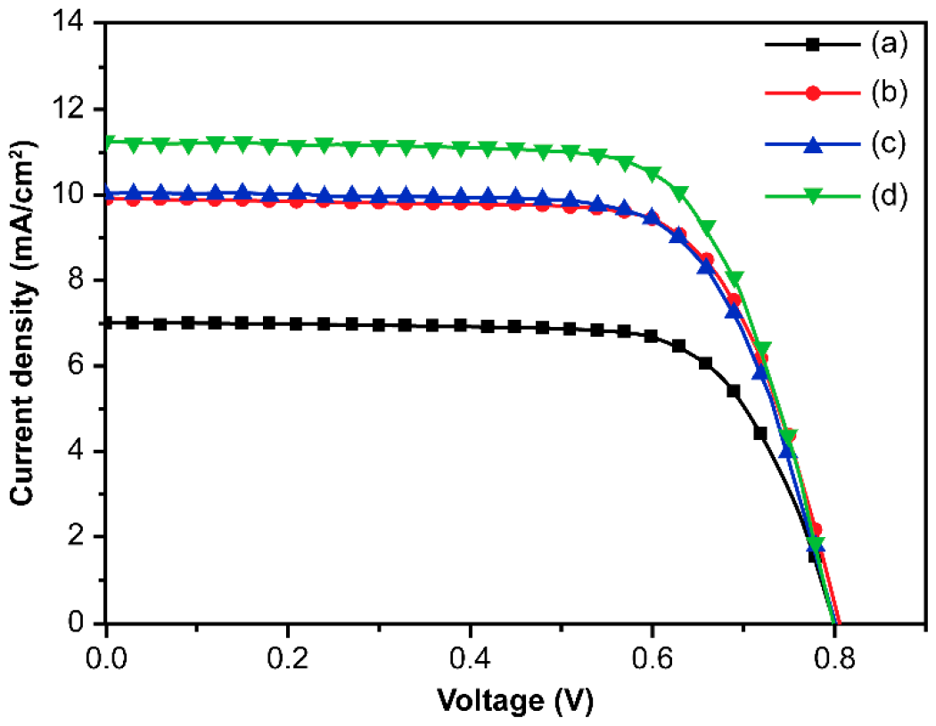
| DSSCs Based on Closed-Ended TiO2 NTAs Decorated | Jsc (mA/cm2) | Voc (V) | ff | η (%) | Dye Loading (nmol/cm2) |
|---|---|---|---|---|---|
| without Ag NPs and carbon materials | 7.02 | 0.81 | 0.72 | 4.10 ± 0.28 | 144 |
| with Ag NPs | 9.92 | 0.81 | 0.72 | 5.73 ± 0.31 | 142 |
| with carbon materials | 10.03 | 0.80 | 0.71 | 5.69 ± 0.26 | 139 |
| with Ag NPs and carbon materials | 11.25 | 0.80 | 0.71 | 6.36 ± 0.34 | 141 |
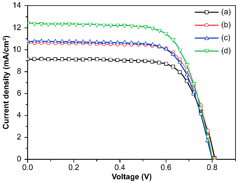
| DSSCs Based on Open-Ended TiO2 NTAs Decorated | Jsc (mA/cm2) | Voc (V) | ff | η (%) | Dye Loading (nmol/cm2) |
|---|---|---|---|---|---|
| without Ag NPs and carbon materials | 9.12 | 0.81 | 0.72 | 5.32 ± 0.36 | 153 |
| with Ag NPs | 10.61 | 0.81 | 0.71 | 6.14 ± 0.46 | 151 |
| with carbon materials | 10.73 | 0.80 | 0.71 | 6.07 ± 0.30 | 147 |
| with Ag NPs and carbon materials | 12.41 | 0.80 | 0.69 | 6.91 ± 0.41 | 149 |
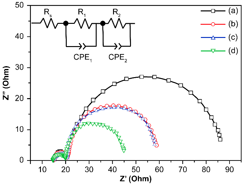
| DSSCs Based on Open-Ended TiO2 NTAs Decorated | Rs (Ω) | R1 (Ω) | CPE1 (F) | R2 (Ω) | CPE2 (F) |
|---|---|---|---|---|---|
| without Ag NPs and carbon materials | 15.50 | 5.58 | 6.91 × 10⁻⁶ | 61.12 | 1.99 × 10⁻³ |
| with Ag NPs | 15.52 | 5.54 | 8.65 × 10⁻⁶ | 36.90 | 2.10 × 10⁻³ |
| with carbon materials | 15.56 | 5.07 | 1.62 × 10⁻⁵ | 36.40 | 2.03 × 10⁻³ |
| with Ag NPs and carbon materials | 14.99 | 4.88 | 1.16 × 10⁻⁶ | 24.55 | 2.99 × 10⁻³ |
© 2017 by the authors. Licensee MDPI, Basel, Switzerland. This article is an open access article distributed under the terms and conditions of the Creative Commons Attribution (CC BY) license (http://creativecommons.org/licenses/by/4.0/).
Share and Cite
Kim, H.-S.; Chun, M.-H.; Suh, J.S.; Jun, B.-H.; Rho, W.-Y. Dual Functionalized Freestanding TiO2 Nanotube Arrays Coated with Ag Nanoparticles and Carbon Materials for Dye-Sensitized Solar Cells. Appl. Sci. 2017, 7, 576. https://doi.org/10.3390/app7060576
Kim H-S, Chun M-H, Suh JS, Jun B-H, Rho W-Y. Dual Functionalized Freestanding TiO2 Nanotube Arrays Coated with Ag Nanoparticles and Carbon Materials for Dye-Sensitized Solar Cells. Applied Sciences. 2017; 7(6):576. https://doi.org/10.3390/app7060576
Chicago/Turabian StyleKim, Ho-Sub, Myeung-Hwan Chun, Jung Sang Suh, Bong-Hyun Jun, and Won-Yeop Rho. 2017. "Dual Functionalized Freestanding TiO2 Nanotube Arrays Coated with Ag Nanoparticles and Carbon Materials for Dye-Sensitized Solar Cells" Applied Sciences 7, no. 6: 576. https://doi.org/10.3390/app7060576