1. Introduction
Manipulators with ultrahigh precision and resolution are urgently needed and play more and more important roles in modern technology, such as atomic force microscopy, ultra precision machining, biological cell manipulation, and chip assembly in the semiconductor industry [
1,
2,
3]. However, conventional mechanisms make it difficult to meet these requirements due to their coarse accuracies caused by inevitable backlash, friction, and joint wear. By contrast, compliant mechanisms, which are composed of rigid links and flexure hinges, transmit motion solely through the deformation of materials. Therefore, they can provide high accuracy and resolution in micro-scale motion, benefitting from no friction, no backlash, no wear, and monolithic structure, while being easy to manufacture and assemble [
4,
5]. This kind of mechanism has already caught researcher’s attention.
A typical compliant mechanism mainly consists of a mechanical structure with flexure members for motion transmission, piezoelectric elements for actuation, ultra-precision sensors for displacement output measurement, and controllers for motion control. Among them, the mechanical structure determines the performance of the compliant mechanism to a great extent. Two kinds of kinematic structures are commonly adopted, i.e., serial and parallel types [
6]. Serial compliant mechanisms generally adopt a stack structure with one 1-DOF positioning stage mounted on another 1-DOF stage. This is a simple structure that is easy to manufacture and control, which has already been successfully applied in commercial products. However, it has the disadvantage of different dynamic characteristics of each axis, a reduced natural frequency as a result of the stacked stage increasing the moving mass, and cumulative motion errors [
7]. The serial compliant stage will be suitable for applications where the motion along one axis is considerably faster than the others. Kenton [
8] utilized a serial-kinematic nanopositioning stage for raster-type scanning, in which one axis is chosen for high-speed scanning while the other is designed for low-speed motion. Compared with the serial type, the parallel structure has inherent advantages in terms of high stiffness, large load capacity, low inertia, high natural frequency, and an absence of accumulation errors [
9]. However, there have been many problems during the development of the parallel manipulator, particularly regarding conventional joints and rigid links. First, there are passive joints in the parallel manipulator, which are difficult to manufacture with high precision, such as sphere and universal joints. Meanwhile, the kinematic chains of the parallel manipulator are generally composed of elongated rods, which are prone to deformation and vibrate under external loads [
10,
11]. Because the displacement output of the terminal platform cannot be measured in real time to realize a closed-loop control, the above adverse factors will significantly decrease the motion accuracy of the parallel manipulator. Moreover, the kinematic model of parallel manipulator is complicated, which creates difficulties in kinematic calibration and motion control. The performance indicators, such as stiffness, dexterity, acceleration ability, will all change when the pose of the manipulator varies. Therefore, conventional parallel manipulators have not achieved their expected success in industry applications. Fortunately, the above issues will cease to be problems when the parallel structure is utilized in the development of a compliant mechanism. Apparently, there are no joints in the compliant parallel mechanism (CPM) and its displacement output can be measured directly as it relates to its micro motion stroke. Moreover, the pose of the CPM can be considered as a constant because its motion stroke is very small when compared to the geometric dimensions. This guarantees that the CPM can have a linear force–displacement relationship, identical mechanical bandwidth for each axis, and even decoupled kinematic model. Therefore, parallel structure has a great potential to be utilized in the development of a compliant mechanism, and numerous researchers have already begun working on it [
12,
13,
14,
15].
Though the CPM has advantages over its rigid counterpart, there are specific challenges in its design and development, which include the realization of cross-axis decoupling and actuation isolation [
16,
17,
18], also known as output and input decoupling. Output coupling refers to any motion along one axis is affected by the actuation/input force along another axis. It results in a complicated kinematic model and additional calibration should be performed in the absence of terminal feedback. This is a typical character of a parallel manipulator due to its parallel kinematic type. The input coupling means that the input force on one actuation stage will cause the primary motion of another motion stage and thus bring additional loads on the actuator. Its effects can be neglected in a conventional parallel manipulator because the adopted motors have large stiffness and can bear any type of reacting force. For a CPM, however, the input coupling will cause unwanted deformations and even clearance between an actuator and the actuation point, which will result in difficulties to the motion control. Moreover, CPM adopts a piezoelectric actuator as its actuation element due to the actuator’s high precision and resolution, large stiffness, high push force, and fast response. However, the piezoelectric actuator is made of multiple piezoelectric layers glued together and is thereby sensitive to pulling and bending forces that may damage the actuator. Therefore, the input coupling has adverse effects on the CPM and should be carefully considered in its design and development process. Awtar [
16,
19] first proposed the decoupling performance design requirements of the parallel XY compliant mechanism. In order to realize actuation isolation, the actuator was required to be connected to the actuation point by means of a decoupler, which transmitted the axial force and absorbed any transverse motion without generating transverse loads. Lai [
20] employed two types of distributed-compliance compound flexure modules and a mirror symmetric structure to reduce the input and output coupling of a novel 2-DOF compliant stage. Qin [
21] utilized statically indeterminate symmetric structures to attenuate the cross-axis coupling of a proposed XY CPM. Li [
22] investigated the design and development of a decoupled compliant stage with displacement amplifiers. The output decoupling was achieved by resorting to compound parallelogram flexures; the double compound parallelogram flexure and the amplifier acted as the decoupler to ensure this stage had excellent input decoupling characteristics.
There have already been several efficient and intuitive design approaches related to the compliant mechanisms, including the kinematic substitution method [
20,
23], constraint-based design method [
24], and freedom and constraint topology [
25,
26]. However, these methods focus on the type synthesis and only guarantee the DOFs of the compliant mechanism instead of considering other performances. Additionally, they regard the degree and constrain of the compliant mechanism as those of the rigid mechanism. While the compliant mechanism moves through the deformations of materials, its DOFs are coupled with the stiffness property. Therefore, the type synthesis and structural design of the compliant mechanism are supposed to be integrated with the consideration of multiple performance indicators. The systematic design method for compliant mechanisms with excellent performances is still a great challenge. The practical CPMs are mostly directly provided in the present studies and there lacks a systematic process for guiding the design of a CPM with excellent decoupling performance. Considering the 2-DOF CPM [
16,
17,
18,
19,
20,
21,
22,
23,
27,
28,
29,
30] is the most practical compliant mechanism, this work’s motivation is to present a systematic design of a decoupled 2-DOF CPM. The requirement on the kinematic structure for realizing totally output decoupling performance has been discussed. A flexure-based decoupler was chosen and its detail structure design was studied to minimize the input coupling of the CPM. Unlike the previous works, which only provided qualitative analyses, the specific definition and analytical model of the input coupling degree (ICD) of the CPM have been provided. According to the established model, the geometric parameters of the 2-DOF were optimized to directly minimize its ICD and the other key performance indicators were also guaranteed through constraint conditions. Finally, a prototype of the 2-DOF CPM was fabricated based on the optimized result, and several experimental tests were performed. A novel method was proposed within the tests, in order to evaluate the input coupling of the 2-DOF CPM by detecting the variations of axial forces at each actuation point instead of measuring their transverse deformations, which is difficult to achieve experimentally. The results demonstrated the decoupled CPM’s excellent performances and also verified the effectiveness of the design method.
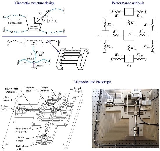
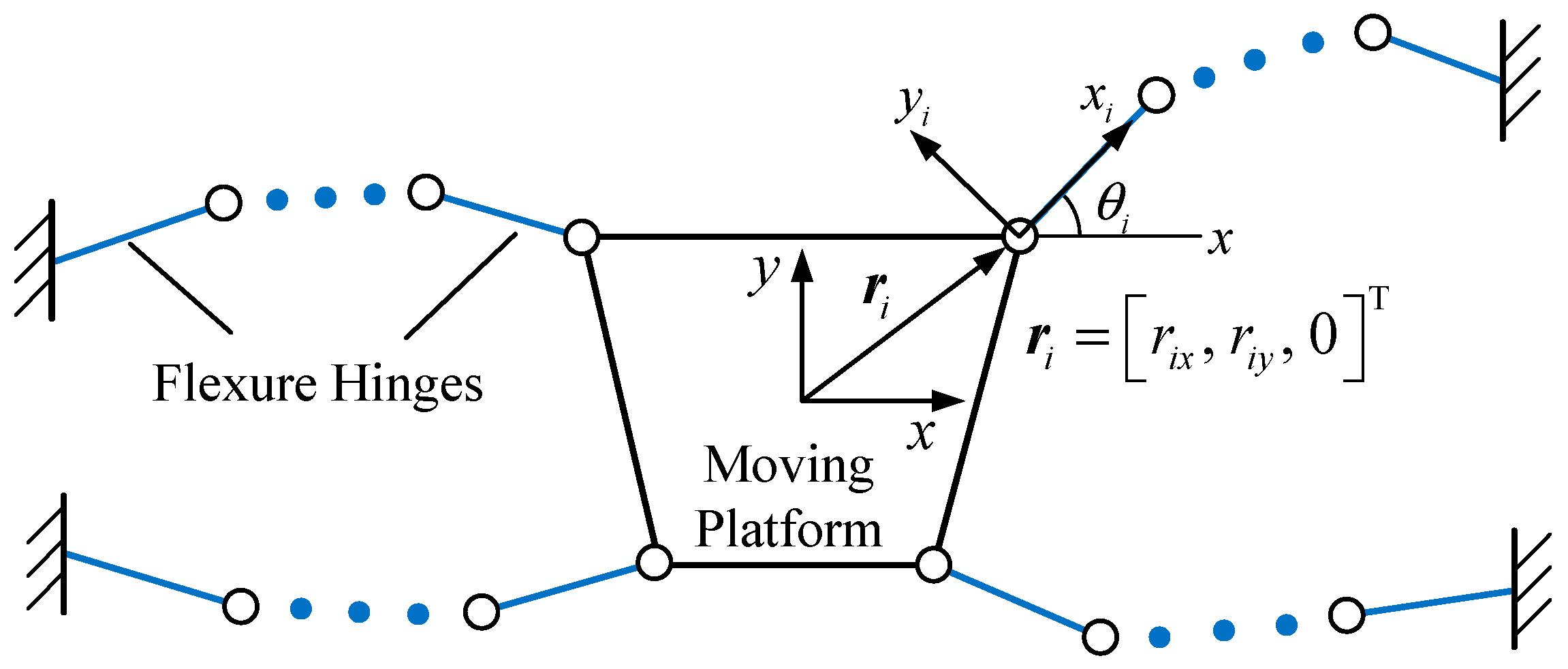
2. Structure Design of the 2-DOF CPM
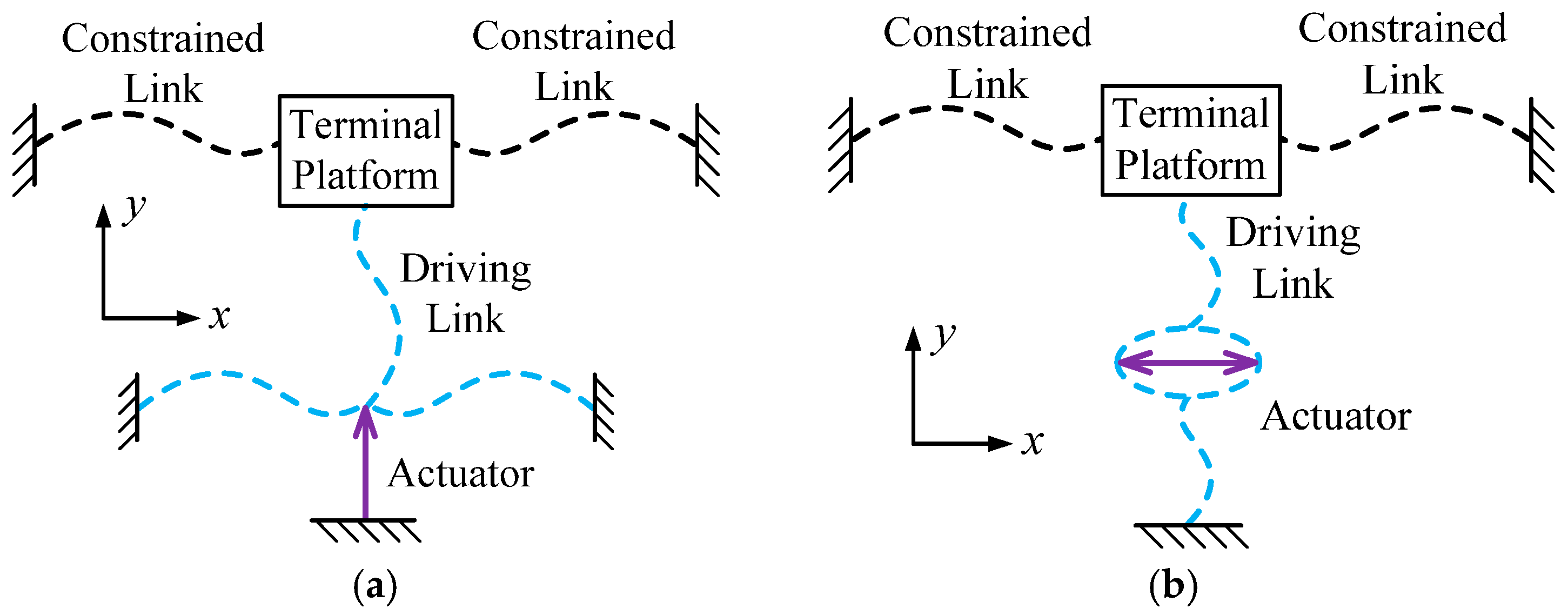
The structure design, compared with geometric parameter optimization, will be more crucial and effective in guaranteeing the CPM’s performance. As stated above, the input and output decoupling performances of the 2-DOF CPM are important and must be well guaranteed. Therefore, the structure of the CPM is determined according to the requirement of the decoupling characteristics in this section. The other performance indicators are ensured by resorting to the geometric parameter optimization in the following material. The schematic of the kinematic structure of the 2-DOF is depicted in
Figure 1.
2.1. Realization of Output Decopuling Performance
The requirement of the output decoupling performance on the structure design of the 2-DOF CPM is studied first. It is expected that translational motion of the terminal platform along the
x- and
y-axes are independent, thereby ensuring the CPM with a total output decoupling characteristic. Therefore, the output stiffness matrix of the CPM should satisfy the form as
The output stiffness of the CPM can be calculated through the summation of the stiffness of each limb as [
31]
where
is the local stiffness matrix of the
ith limb, and
Tif and
Tid are the force and displacement transformation matrices, respectively, which take on the form
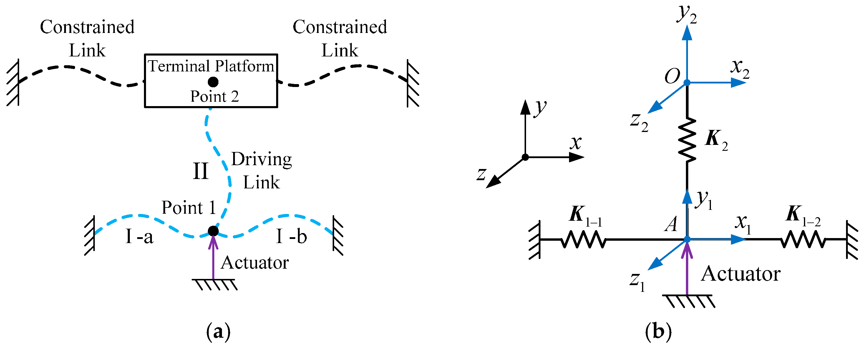
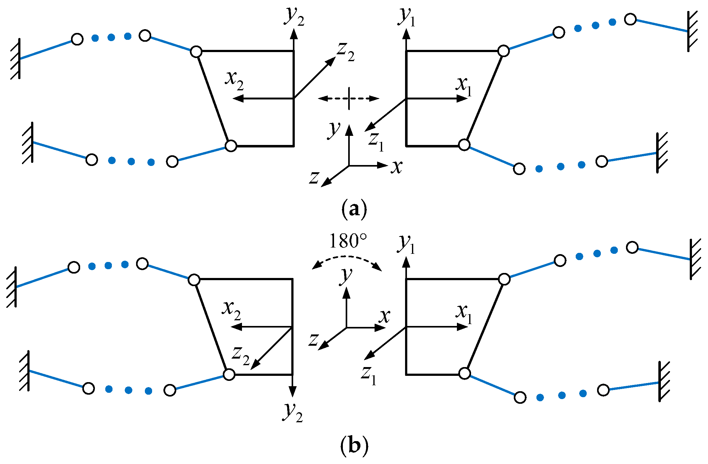
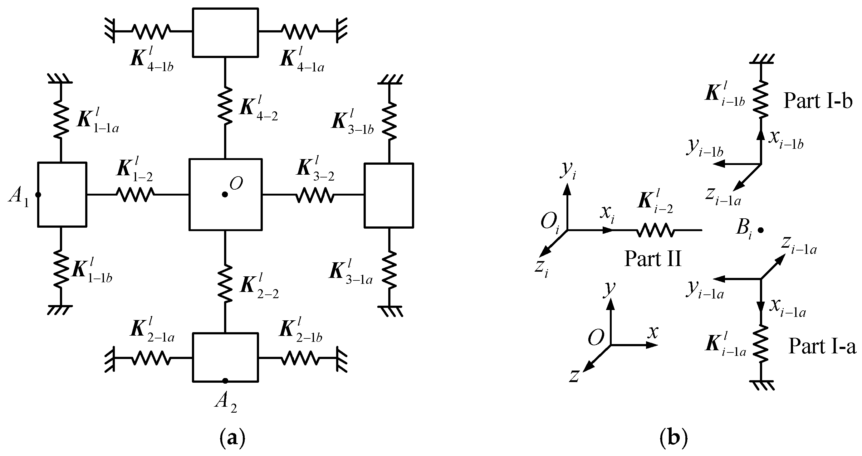
The output stiffness matrix of the CPM should satisfy the form expressed in Equation (1). However, it is difficult to obtain a satisfied structure by solving the equations directly. To simplify this problem, the structure of the CPM is divided into two parts and the local coordinate systems of each subsystem are established, as shown in
Figure 2. There are two ways to build the local coordinate systems, i.e., mirror symmetry and rotation symmetry.
The stiffness matrices of the two subsystems shown in
Figure 2a under their corresponding local coordinate systems are expressed as
Then, the stiffness matrix of the CPM under the globe coordinate system can be obtained according to Equation (2) as
where
, and
.
If the structure of the CPM is mirror symmetry, the local stiffness matrix of the two subsystems satisfies
. Then Equation (5) can be simplified as
This shows that the translational motion along the y-axis will not affect the other two axes, while the translational motion along the x-axis and the rotational motion about the z-axis are coupled.
Similarly, when the structure of the CPM is rotation symmetry, its stiffness matrix can be obtained as
This indicates that the rotational motion about the z-axis has no influence on the other two axes, while the translational motions along the x- and y-axes are coupled.
It is verifiable that, when the structure of the CPM both satisfies the mirror and rotation symmetry, the translational and rotational motions of the terminal platform are independent. It is clear that the CPM is symmetric around the
x- and
y-axes when it satisfies both the mirror and the rotation symmetry. In order to obtain a total output decoupling characteristic, the actuation forces must be applied along the two symmetric axes at the same time. Therefore, linear actuators are needed, such as the piezoelectric actuator [
32] and voice coil motor [
33], which should be mounted along the symmetric axes. The above discussion shows that a symmetric kinematic structure can sufficiently ensure the 2-DOF CPM with total output decoupling performance.
2.2. Realization of Input Decopuling Performance
Next, the requirement of the input decoupling performance on the structure design of the 2-DOF CPM is investigated. The effective way of reducing the input coupling of the CPM is to adopt a flexure-based decoupler between an actuator and the terminal platform. There are two types of the decouplers, and their kinematic structures are shown in
Figure 3.
The difference between the two decouplers is the actuator’s mounting type. The actuator is fixed on the ground in the first decoupler, while the other installs the actuator on the moving part. The actuator can be inserted into a displacement amplifier in the second decoupler, which increases the motion stroke of the CPM and gives the actuator double protection from input coupling. However, this type of decoupler results in a more complex structure. Moreover, the actuator increases the moving mass of the CPM and thus reduces its natural frequency. Therefore, the first type of decoupler is preferred for this paper, and its detailed structure design will be investigated to guarantee the input decoupling characteristic of the CPM. Because of the symmetric structure of the 2-DOF CPM, we can choose the decoupler along the
y-axis as the study object and its stiffness model is shown in
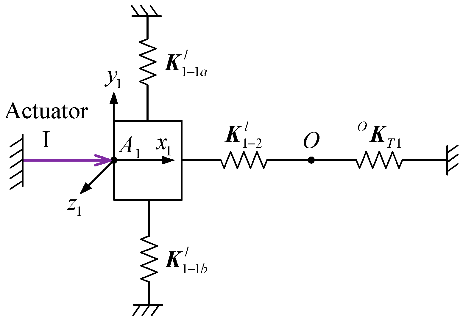
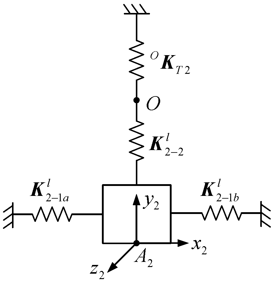
Figure 4.
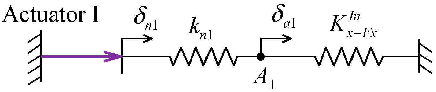
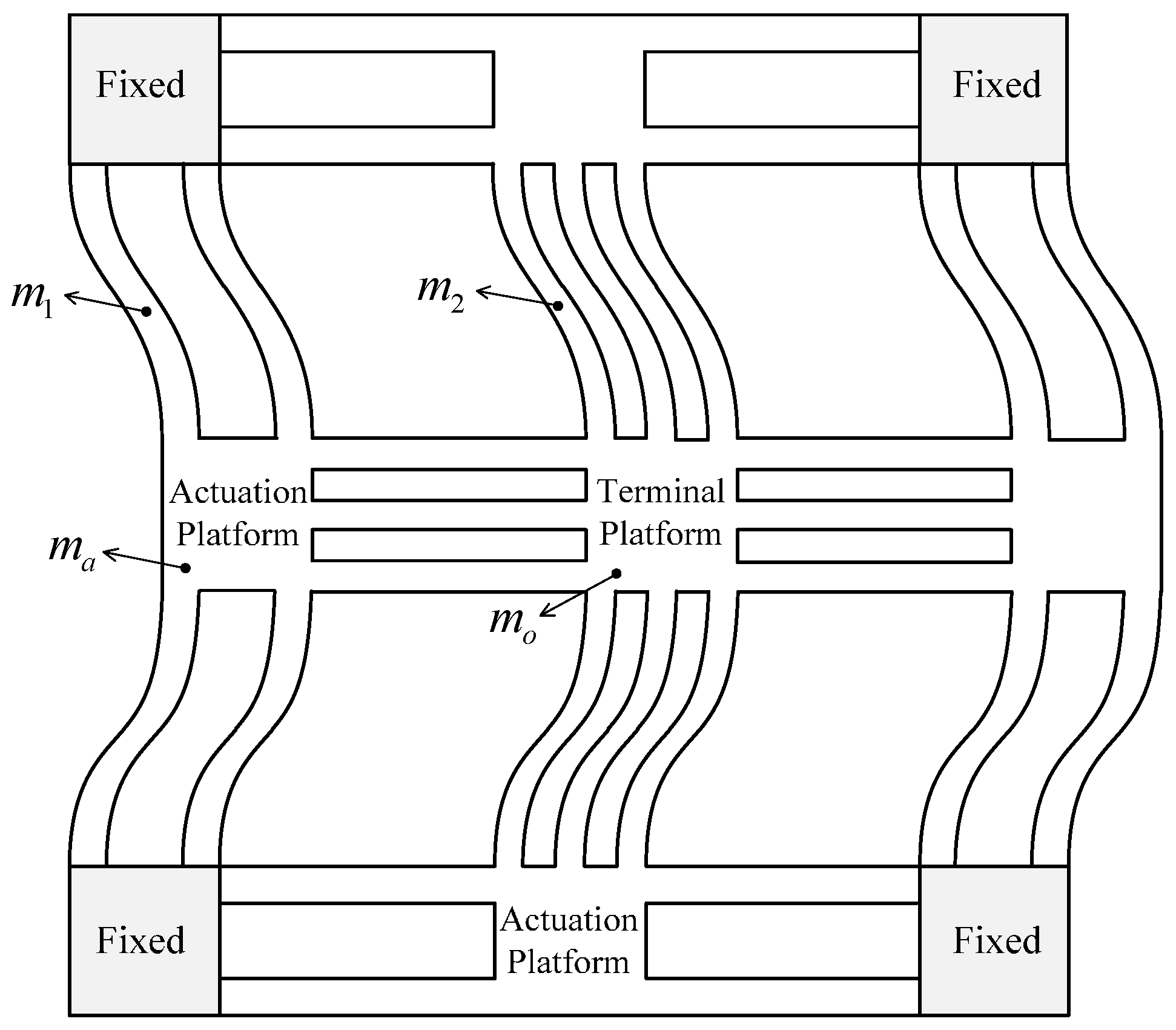
For the 2-DOF CPM, excellent input decoupling performance requires that the transverse and rotational deformations at one actuation point are small enough that the terminal platform is actuated by the other actuator. According to
Figure 4, utilizing a force equilibrium condition of point
A1 allows us to obtain the relationship between the displacement of the terminal platform and the deformation at the actuation point as
where
δo is the is the displacement of the terminal platform,
δa is the deformation of actuation point
A1, and
K1 and
K2 are the stiffness matrices of Parts I and II of the decoupler expressed in the coordinate frame {
A-
x1y1z1}, respectively.
The bending and rotational deformations at the actuation point caused by the motion of the terminal platform can be obtained through the components of δa; they are expected to be as small as possible. Through a qualitative analysis of Equation (8), the stiffness requirement of the decoupler is: the bending stiffness along the x-axis and the rotation stiffness about the z-axis of Part II should be much smaller than in Part I. With the exception of protecting the actuator from suffering transverse load, the decoupler also transmits the motion of the actuator to the terminal platform. Therefore, the axial stiffness along the y-axis of Part I should not be too large, in order to avoid the motion stroke of the actuator losing too much because of its deformation. In addition, the axial stiffness of Part II should be large in order to reduce the motion lost between the actuator and the terminal platform, thereby improving the motion transmission efficiency.
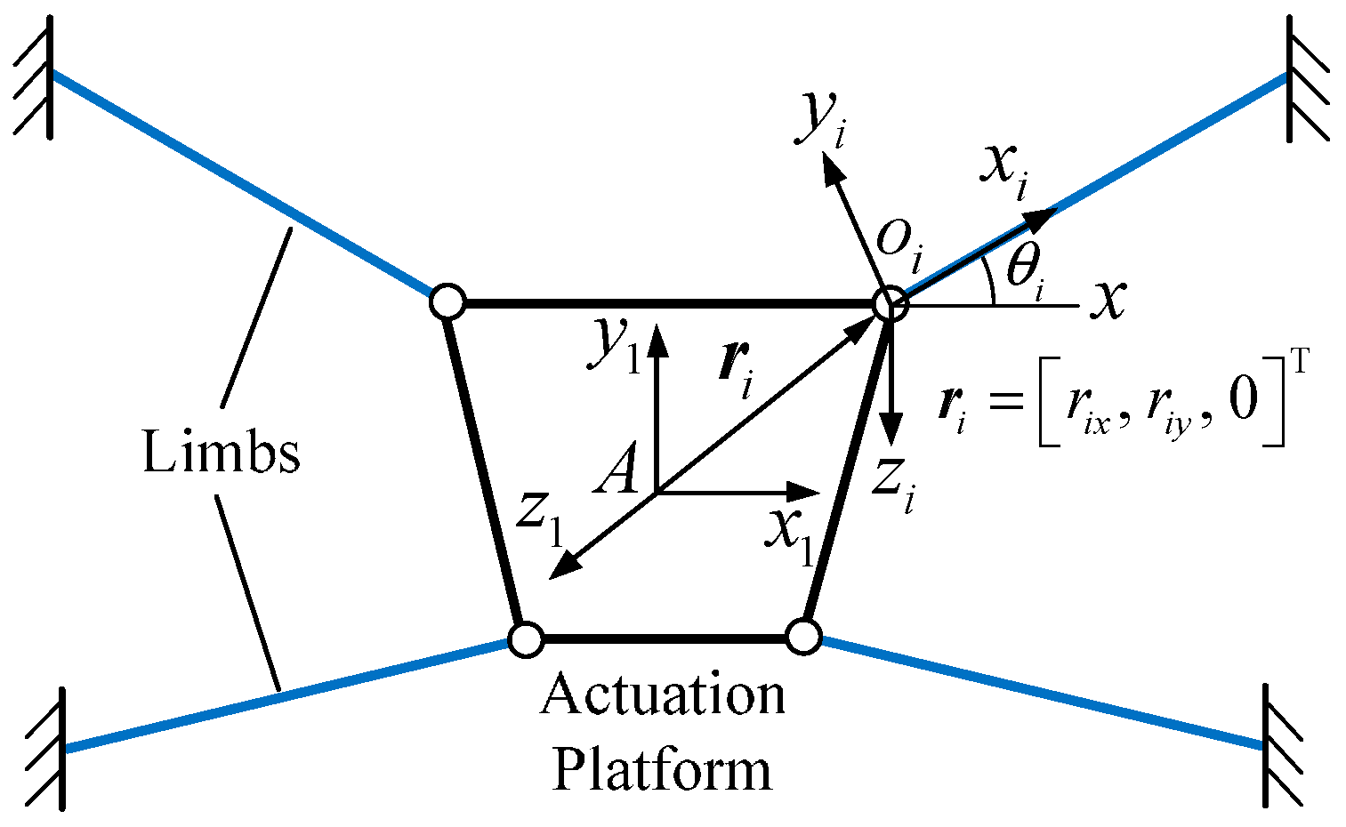
The design requirements on the decoupler will be utilized to guide its detailed structure design. The kinematic structure of Part I of the decoupler adopts a parallel type, as shown in
Figure 5. In order to obtain a compact structure, the limb is constructed from a single leaf spring due to its advantages of compact size, lightweight, and easy manufacturing [
34,
35].
The stiffness of Part I is the summation of the stiffness of each limb. Therefore, the influence of each limb’s mechanical parameters on the stiffness of Part I is investigated first. The stiffness of the
ith limb can be expressed in the coordinate system {
A-
x1y1z1} as
where
is the stiffness matrix of the
ith limb expressed in its local coordinate frame {
o-
xiyizi}, which takes the form
The axial and bending stiffness of the limb can be obtained from Equation (9) as
Considering the stiffness components of the leaf spring satisfy kix−Fx kiy−Fy, the value of angle θi should be zero to ensure the large bending stiffness and small axial stiffness of Part I.
Then the rotation stiffness of the limb can be written as
Because each component of the stiffness matrix kil is greater than zero, the increment of rix and riy will both increase the rotation stiffness.
According to the discussion above, in order to meet the stiffness requirement of Part I of the decoupler, each limb should be parallel to the x-axis and their positions should be far from the centric of the actuation platform if possible.
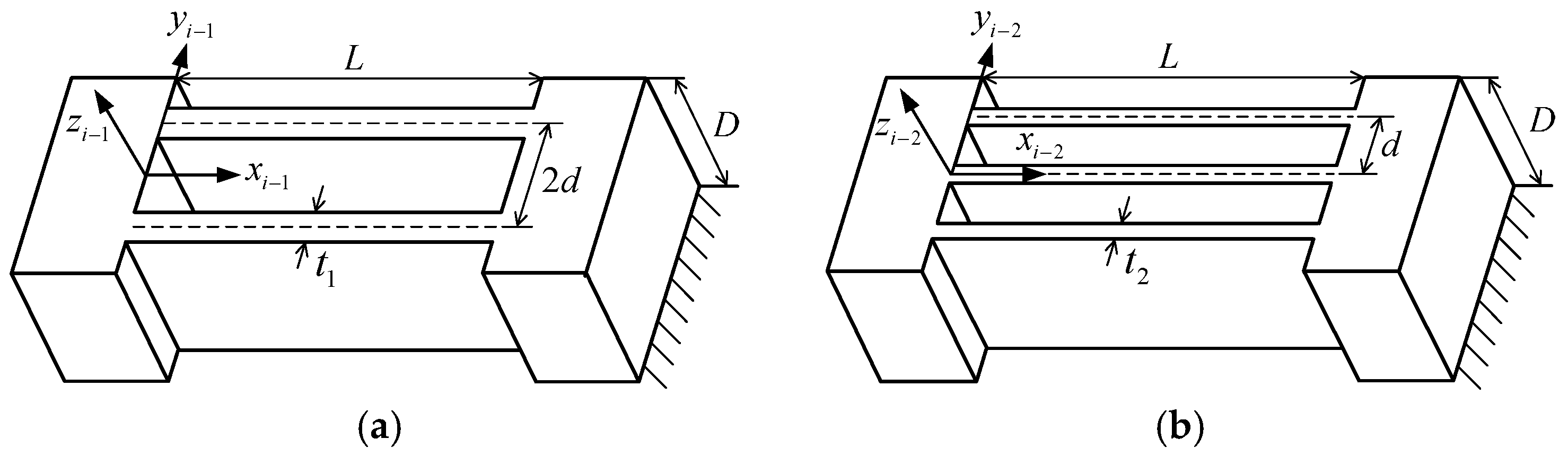
Next, the influence of the leaf spring’s geometric parameters is studied. The stiffness matrix of a single leaf spring can be expressed as
where
E is the elastic modulus, and
L,
t, and
D are the length, thick and height of the leaf spring, respectively.
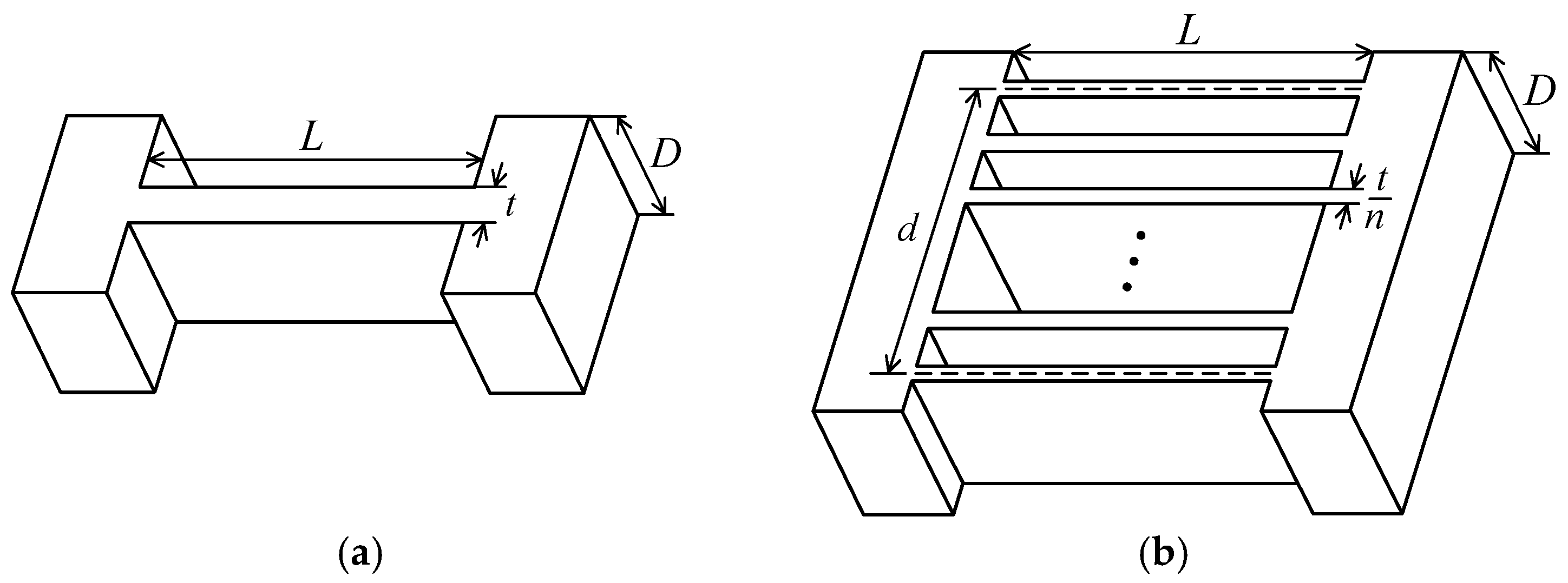
According to the stiffness requirement of Part I and the above analysis, the bending stiffness of the leaf spring should be small, while the axial and rotation stiffness should be large. According to Equation (13), however, it is impossible to reduce the bending stiffness of the single leaf spring while guaranteeing that the axial and rotation stiffness remain unchanged or increased by adjusting its geometric parameters. Therefore, another type of hinge should be proposed to construct a satisfied limb. As opposed to utilizing a single flexure hinge, a compound hinge composed of
n identical parallel leaf springs is chosen, as shown in
Figure 6.
The length, height and total mass of the compound hinge are the same as the single leaf spring, and its stiffness matrix can be expressed as
where
, and
k1m−n is the stiffness component of the single leaf spring.
Equation (14) shows that the axial stiffness of the compound hinge is equal to the single leaf spring, and the bending stiffness is always smaller and decreases rapidly as number n grows. The rotation stiffness depends on the number n and parameter γ. When γ > 1, the rotation stiffness is always larger than that of a single leaf spring. Therefore, the compound hinge will meet that requirement quite well.
Because the stiffness requirement of Part II of the decoupler is contrary to Part I, its limbs should be parallel to the y-axis according to the investigation above. The leaf spring is still utilized to construct the limbs in Part II and its stiffness requirement is illustrated as: the axial stiffness should be large while the bending and rotation stiffness should be small. The heights of the flexure hinges adopted in Parts I and II are the same due to the monolithic structure of the CPM. In this case, no matter what, the single leaf spring and the compound hinge cannot meet the stiffness requirement. Considering the terminal platform of the 2-DOF CPM only has the translation motion, minimizing the bending stiffness and shear stiffness ka−Fy can ensure the decoupler with an excellent decoupling character according to Equation (8). The bending and shear stiffness of the compound hinge all decrease sharply as the number n grows. Therefore, the compound hinge is still the best choice when constructing the limbs of Part II of the decoupler.
As mentioned above, the excellent input decoupling character requires that the bending and shear stiffness of the compound hinges of Part II are small, and the axial and rotation stiffness of the compound hinge of Part I are large. Except for the axial stiffness, the other stiffness components of the compound hinge will all decrease as number n increases. Therefore, the number n of the compound hinge of Part I would be greater than that of Part II. In addition, the number n of the compound hinge should not be overly large, due to difficulties in manufacturing and because it is then prone to buckling under axial load. Taking all these factors into consideration, the number n of the compound hinges of Parts I and II are chosen to be two and three respectively in this paper.
2.3. Detailed Structure of the 2-DOF CPM
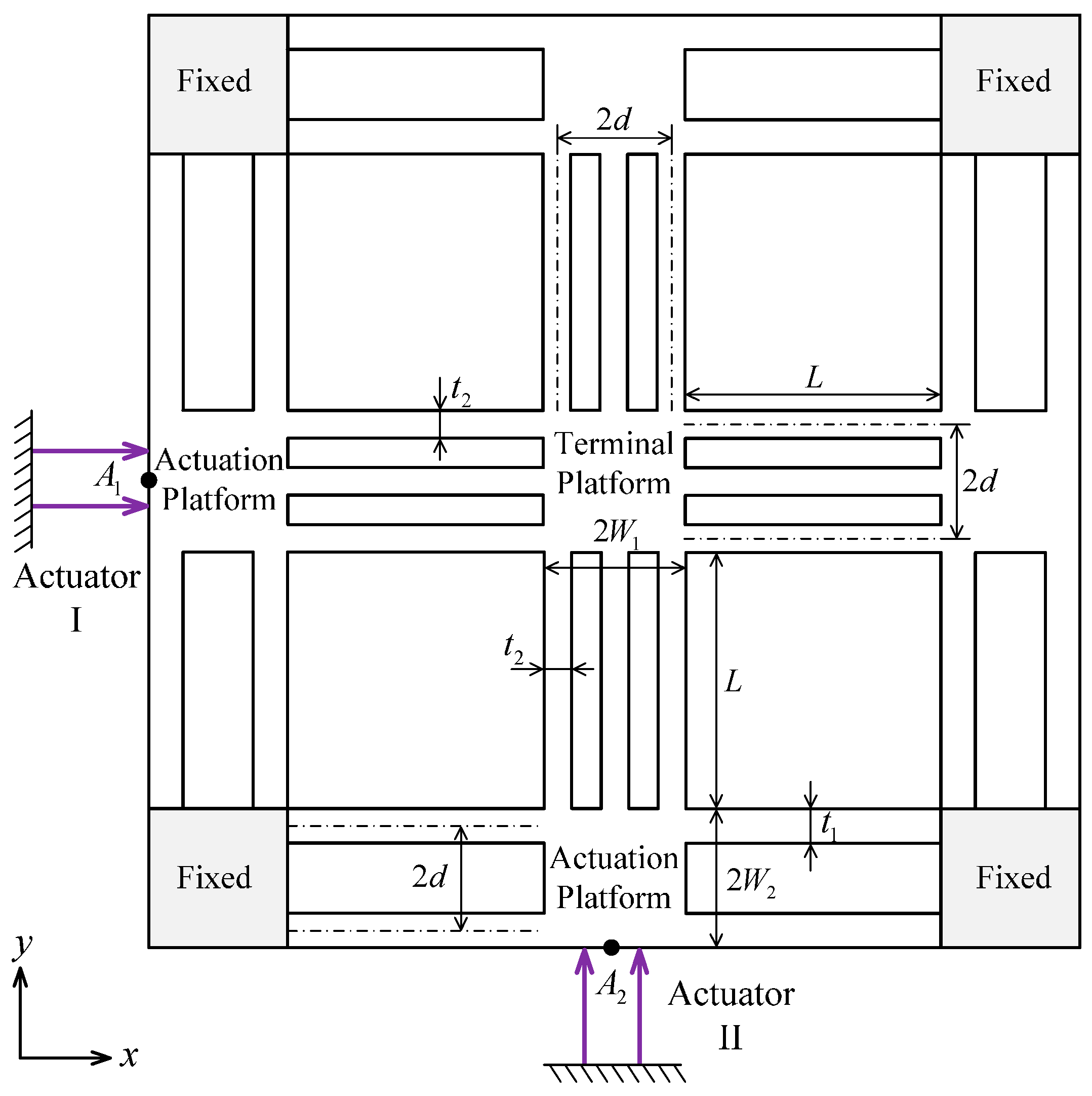
According to the discussion above, the detailed structure of the 2-DOF CPM is given in
Figure 7. The output decoupling performance of the CPM is realized by the symmetric kinematic structure, and the input coupling is reduced by the flexure-based decoupler composed of the compound hinges.
4. Geometric Parameters Optimization and Performance Evaluation
4.1. Geometric Parameters Optimization
To ensure the excellent performances of the 2-DOF CPM, it is necessary to optimize its geometric parameters. The optimum goal is to guarantee the excellent decoupling performance of the CPM. Because the symmetric structure of the CPM already possesses a total output decoupling character, the minimization of the input coupling will be selected as the optimization objective, i.e., min (ICD). The CPM is fabricated from a single block with a specific thickness of 15 mm, and the independent geometric parameters to be optimized are L, t1, t2, and d. The other performances of the CPM, including the workspace, output rotation stiffness, and natural frequency, are guaranteed by the constraint conditions described as follows.
- (1)
Workspace: δx × δy ≥ 47.5 μm × 47.5 μm. According to the analytical models, the workspace of the CPM is influenced by the stiffness of the actuator and the mechanism, and is also limited by the maximum stress of the materials. The nominal motion stroke of the piezoelectric actuator adopted in this CPM is 60 μm, and its static axial stiffness is about 15 N/μm. Additionally, alloy Al-7075 with a yield stress of 525 MPa is chosen to fabricate the CPM. According to the given workspace, Equations (24) and (26) can be utilized to determine the satisfied ranges of the geometric parameters.
- (2)
Output rotation stiffness: Kα ≥ 3.5 × 10⁴ Nm/rad. The translational deformations of the terminal platform caused by external loads along the x- and y-axes can be compensated through the closed-loop control. However, the rotational deformation about the z-axis cannot be compensated, and thus will affect the motion precision of the CPM. Therefore, the output rotation stiffness is expected to be large enough.
- (3)
Natural frequency: f ≥ 800 Hz. The first two natural frequencies of the 2-DOF CPM are identical and correspond to the translational vibration modes along the two axes. Therefore, they should be as high as possible to guarantee the CPM with a rapid dynamic response and robustness against the disturbances.
The optimization process of the CPM’s geometric parameters is performed with the “fmincon” function. It is an optimization function in MATLAB used to find a constrained minimum of a scalar function of several variables and its grammar is given as
where
x is the optimized solution, fval is the value of the objective function at the solution
x, fun is the objective function,
x0 is the initial point for
x,
A is the matrix for linear inequality constraints,
b is the vector for linear inequality constraints,
Aeq is the matrix for linear equality constraints,
beq is the vector for linear equality constraints,
lb is the vector of lower bounds,
ub is the vector of upper bounds, and nonlcon is the nonlinear constraint function.
The minimization of the ICD is adopted as the objective function and the requirement of the workspace, output rotation stiffness, and the natural frequency of the CPM are used as the nonlinear constraint conditions in the “fimincon” function. There are no linear inequality and linear equality constraints in the geometric parameters optimization, and therefore set A = [], b = [], Aeq = [], beq = []. Additionally, the ranges of the geometric parameters are given as 50 mm ≤ L ≤ 75 mm, 1 mm ≤ t1 ≤ 5 mm, 1 mm ≤ t2 ≤ 5 mm, 5 mm ≤ d ≤ 10 mm, and their initial values are given as L = 60 mm, t1 = 3 mm, t2 = 3 mm, and d = 7.5 mm. Finally, the optimized parameters are obtained as L = 50 mm, t1 = 3.56 mm, t2 = 2.57 mm, and d = 10 mm. The ICD of the optimized CPM is as low as 0.279%, which indicates that the 2-DOF CPM possesses an excellent input decoupling character. The analytical results of other performance indicators are also obtained. The results show that the CPM has a workspace of 47.54 μm × 47.54 μm. The input and output stiffness are 3.68 N/μm and 3.50 × 10⁴ Nm/rad, respectively. In addition, the natural frequency is 876 Hz. The analytical results show that the key performances of the optimized CPM all satisfy the design requirements.
4.2. Performance Evaluation with Finite Element Analysis
The optimized mechanism’s performance will be evaluated through FEA, performed with the ANSYS WorkBench software (Workbench 14.5, ANSYS Inc., Cannonburg, PA, USA). The physical and mechanical parameters of the adopted material alloy Al-7075 are: Young’s modulus = 71.7 GPa, Poisson’s ratio = 0.33, Density = 2770 kg/m3, and yield stress = 525 MPa.
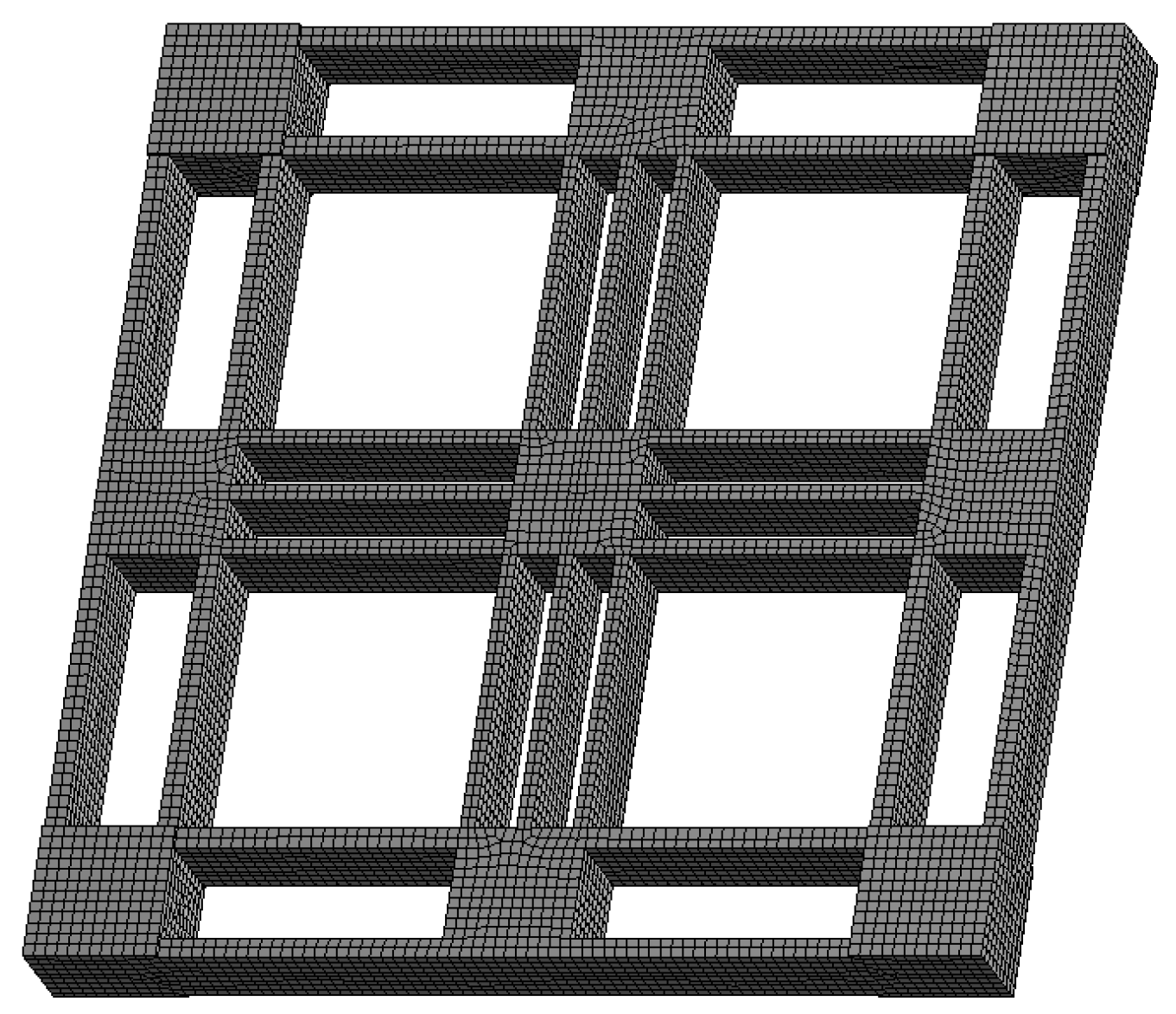
A good finite element model with a reasonably high number of DOFs is first required to guarantee the accuracy of FEA results. The finite element model of the CPM is presented in
Figure 16, wherein the mesh is generated by using the hex dominant method. The maximum element size is set as 2 mm and the numbers of the nodes and elements are 139,471 and 32,016, respectively.
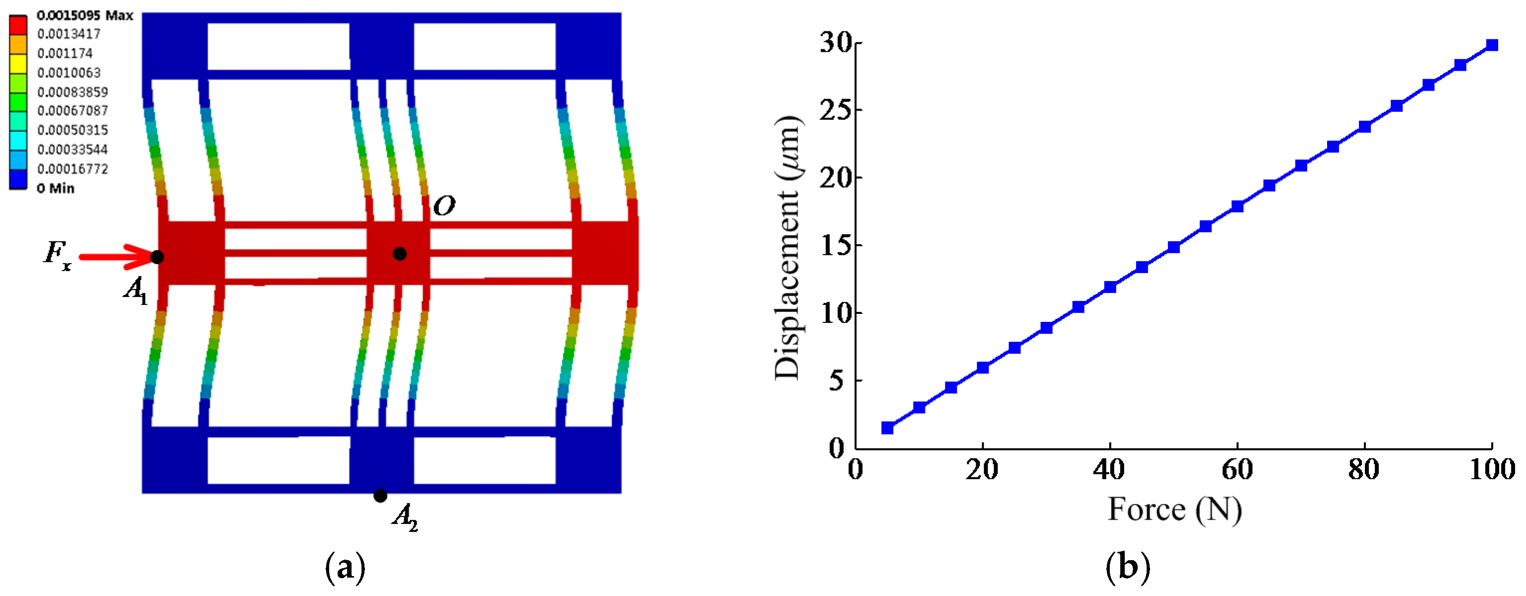
The input axial stiffness of the CPM is calculated by applying a force at the actuation point
A1, as shown in
Figure 17a. The relationship between the applied force and the deformation at point
A1 is obtained and is given in
Figure 17b. The force–displacement curve fits into a line very well, which indicates the linearity of the CPM. The input axial stiffness is obtained by calculating the slope of the fitted line and resorting to the least squares method, which is 3.36 N/μm. In actual CPM, preloading and actuation forces will cause initial displacements along each axis, which may influence the CPM’s stiffness. Taking a small initial displacement (less than 100 μm) along one axis into consideration, both the theoretical and finite element models have demonstrated that the CPM’s stiffness remains unchanged.
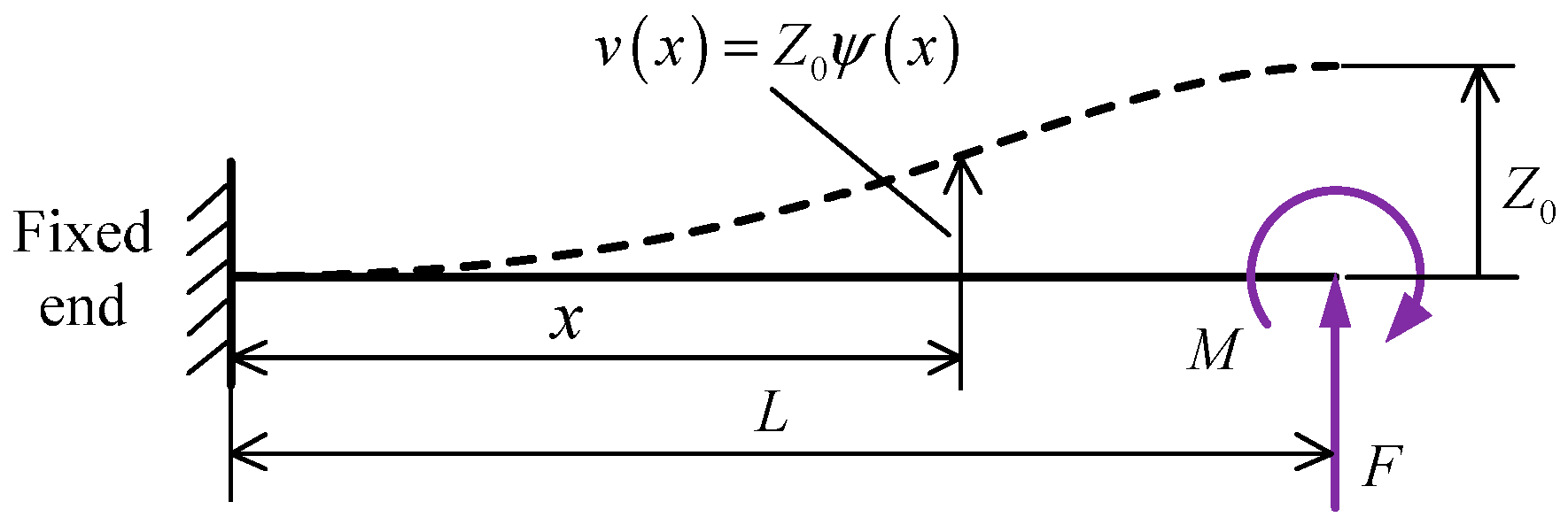
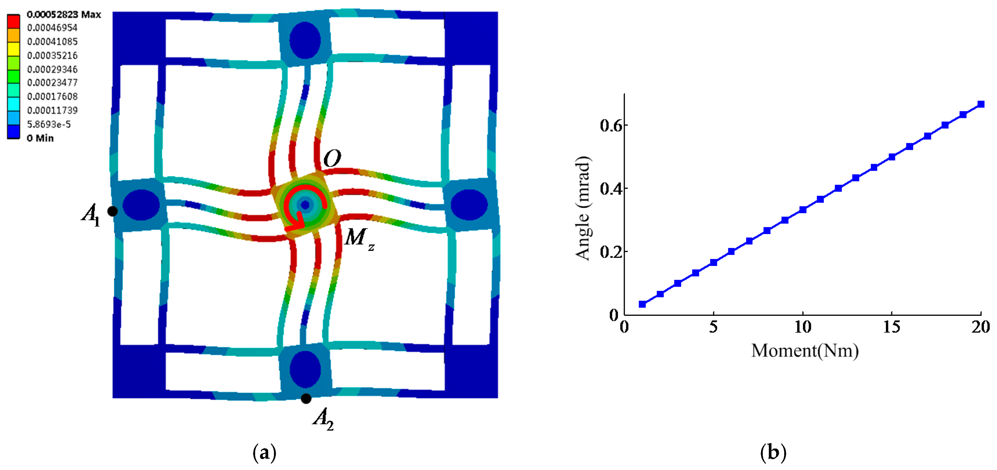
Similarly, the output rotation stiffness of the CPM can be analyzed through applying bending moment at the terminal platform, as shown in
Figure 18a. The relationship between the rotation angle and applied moment is given in
Figure 18b, and the output rotation stiffness can be calculated as 3.33 × 10
4 Nm/rad.
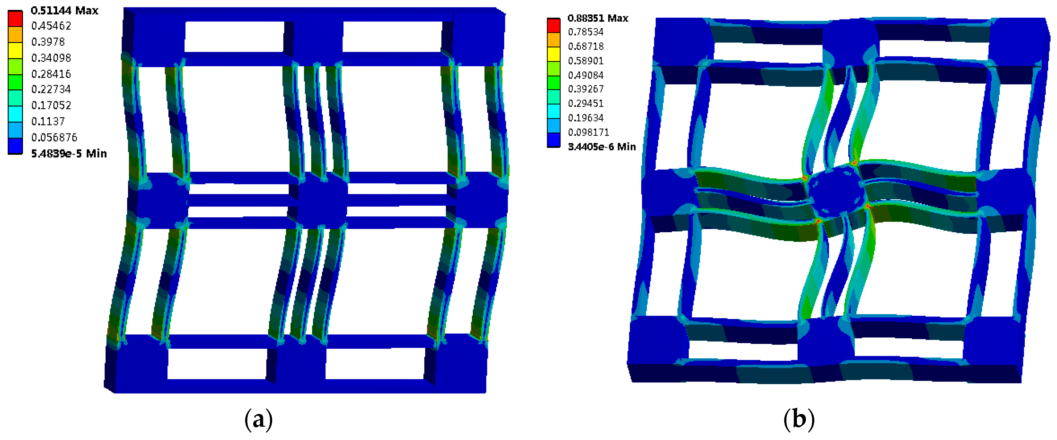
It can be observed that the input axial stiffness and the output rotation stiffness of the CPM calculated through FEA are 8.7% and 4.9% smaller than the theoretical values. The reason is because the actuation platform and terminal platform are considered to be rigid parts in the analytical model, but they also suffer deformation under the applied loads. This is evident from the stress distribution diagrams shown in
Figure 19. Therefore, the compliance of the platforms reduces the stiffness of the CPM.
The finite element model shown in
Figure 17a can be utilized to calculate the ICD of the CPM. When the driving force 100 N is applied at the actuation point
A1 along the
x-axis, the axial deformation at point
A1 and the bending deformation at point
A2 are 29.8 μm and 8.66 × 10
−2 μm, respectively. The ICD can be calculated as 0.291%, which is close to the theoretical value. This not only verifies the validity of the analytical model but also demonstrates the excellent input decoupling characteristic of the CPM.
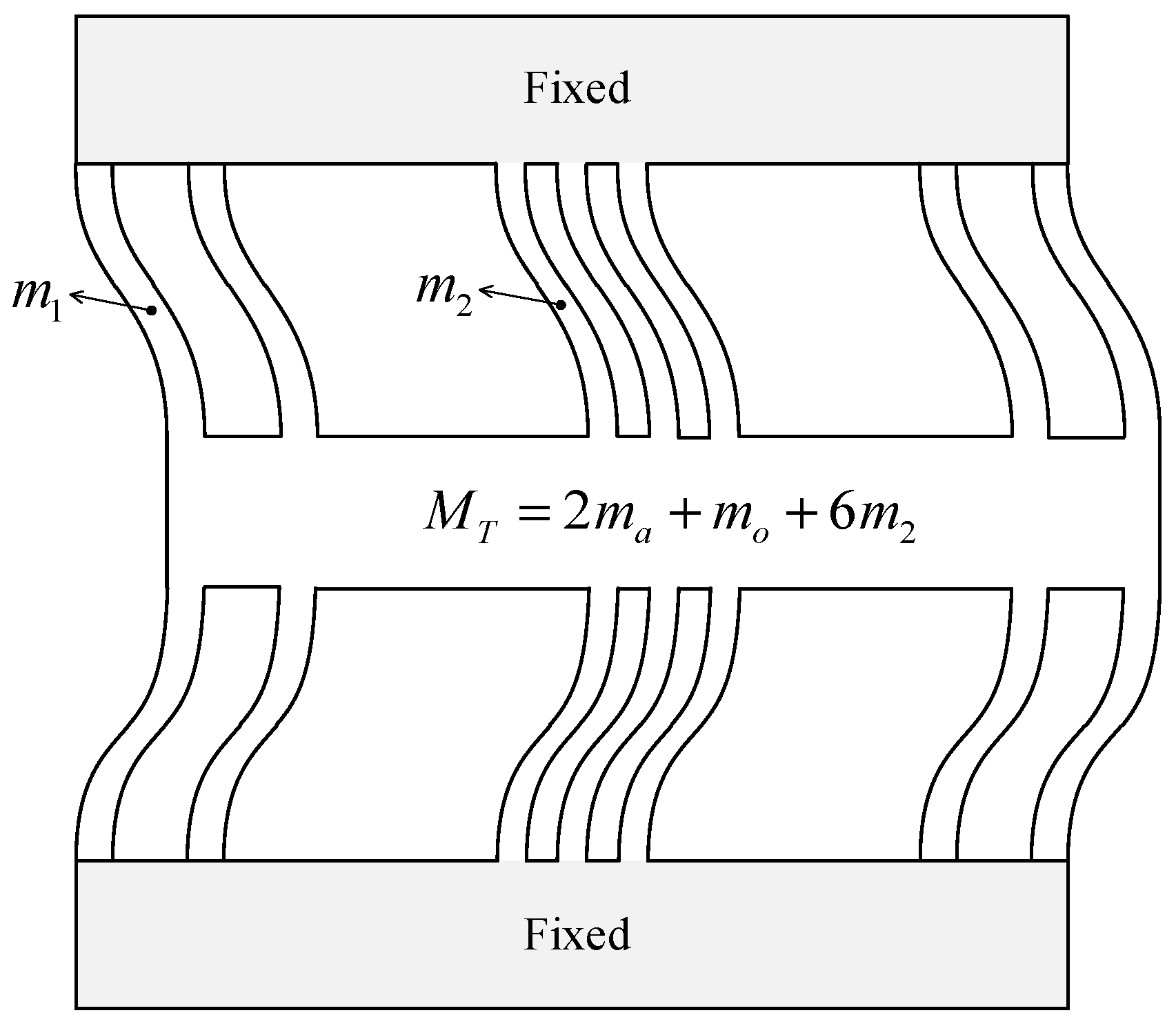
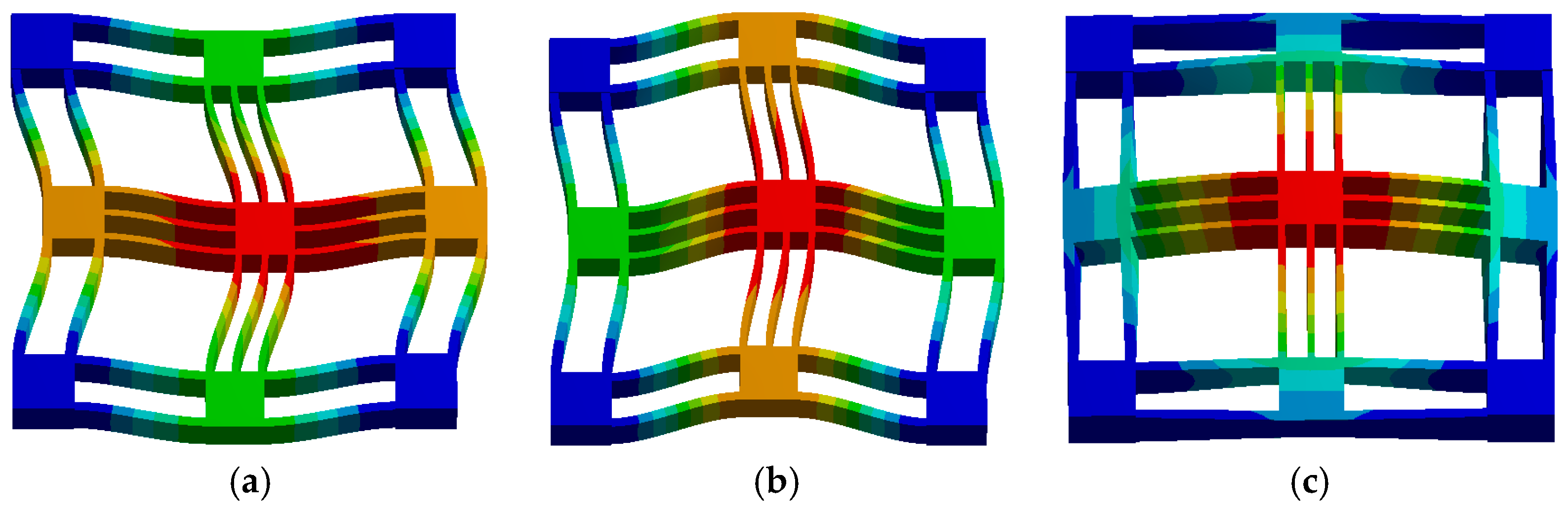
Furthermore, the resonant frequencies and corresponding vibration modes of the CPM are also simulated. The first six natural frequencies are 808 Hz, 808 Hz, 1802 Hz, 3153 Hz, 3153 Hz, and 3430 Hz, and the first three vibration modes are shown in
Figure 20. The simulation results show that the first two natural frequencies are identical, and their vibration modes exist along the
x- and
y-axes, which correspond to the structural characteristic of the CPM. The third vibration mode is out-of-plane motion and its frequency is more than twice as large as the first two natural frequencies. Additionally, the rotational vibration mode corresponds to the eighth vibration mode with a frequency of 4636 Hz. Therefore, the vibration modes with higher frequencies have less of an effect on the translation motion of the CPM. Compared with the simulation results, the analytical model overestimates the first two natural frequencies with a derivation of 8.4%. This may arise from an overestimation of the equivalent stiffness in Equation (30). The more accurate equivalent stiffness can be replaced by the simulated input axial stiffness, and the first two natural frequencies can be calculated as 805 Hz, which is close to the simulation result.
5. Experimental Test
In this section, a prototype of the 2-DOF CPM was fabricated and several experimental tests were carried out to evaluate its performance and demonstrate the effectiveness of the proposed design method. Referring to the optimized results, the dimensions of the prototype were selected as:
L = 50 mm,
t1 = 3.5 mm,
t2 = 2.5 mm, and
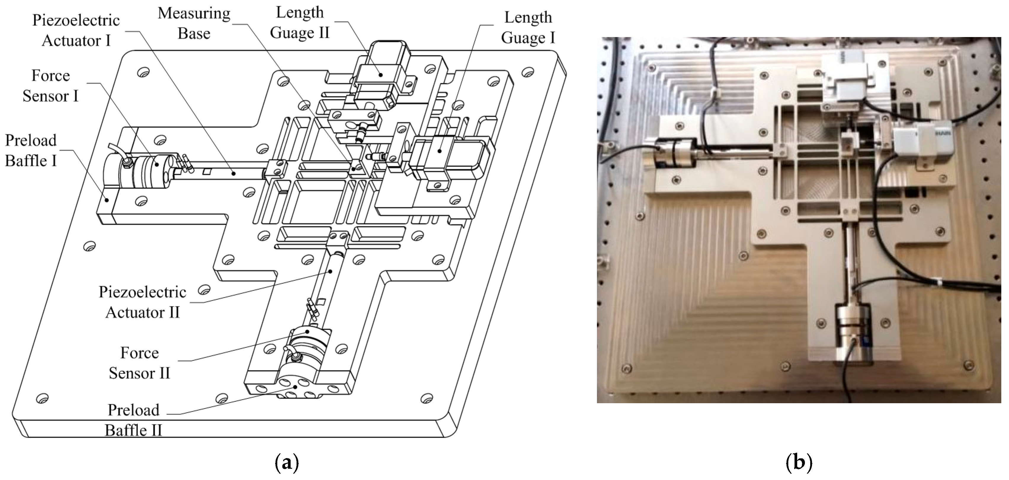
d = 10 mm. The 3-D model and the experimental table of the 2-DOF CPM are shown in
Figure 21. The main body of the CPM was fabricated using the milling process with a single block of Al-7075. From the stress diagrams shown in
Figure 19, we can see there is a concentration of stress where the leaf springs connect to the platforms and the fixed base. Therefore, fillets with a 2 mm radius were machined at both ends of the flexure members to reduce the effects of stress concentration. Two 60-μm-stroke piezoelectric actuators (P-843.40 from Physik Instrument) were adopted to drive the stage. They were driven by a modular piezo controller & driver (E-621 from Physik Instrument), which generates voltage up to 120 V. Two force sensors (U93-1kN from HBM) were mounted at the end of each actuator to detect their actuation forces. Compared to mounting them in front of the actuators, this installation type reduces the moving mass of the stage and thus improves its dynamic response. A four-channel high dynamic signal processor (MX410 from HBM) was utilized to amplify and record the analog voltage output of the force sensors. The displacement outputs of the terminal platform along the two axes were measured using two high precision length gauges (MT-1281 from Heidenhain). A DSPACE processor board DS1007 equipped with a 16-bit ADC card (DS2004), a 16-bit DAC card (DS2101), and a six-channel incremental encoder interface card (DS3002) was utilized to output the excitation voltage for the piezo servo controller and capture the data from the force sensor signal processor and length gauges. Preloads were applied along the two axes through preload baffles to prevent the piezoelectric actuators from suffering pulling forces during the motion process and to eliminate the clearances between the actuators and the mechanism. The preloading forces were detectable by the force sensors and they were set to about 300 N initially.
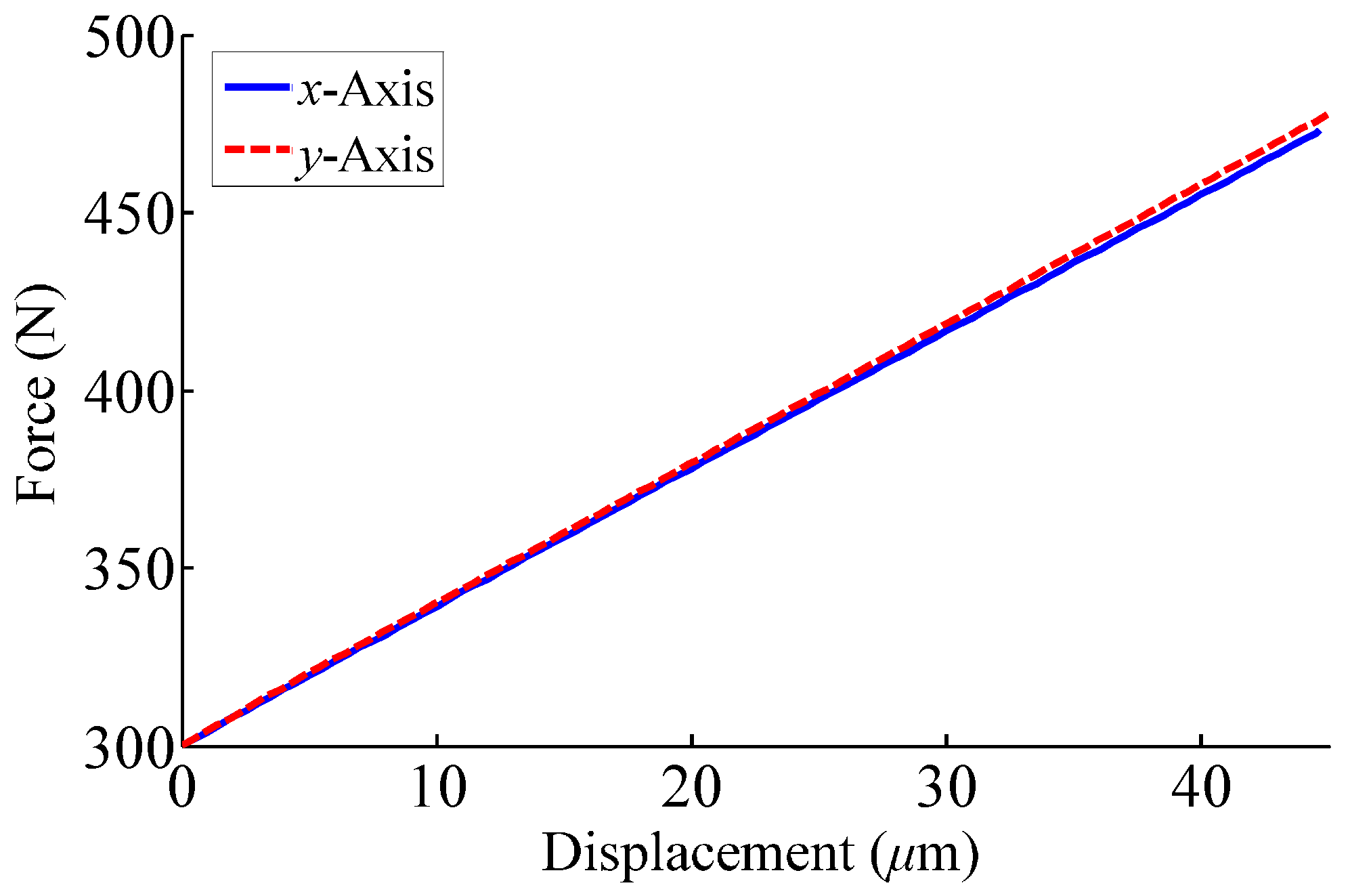
The input axial stiffness along the two axes was tested first. The actuation forces were detected using the force sensors and the displacements were measured using the length gauges.
Figure 22 shows the relationship between the tested actuation forces and the corresponding displacements along the two axes. The tested displacement–force curves fit into lines well and indicate the stiffness of the CPM is linear, which will be easy to control. The least squares method was utilized to fit the results and the input axial stiffness of the CPM was calculated as 3.87 N/μm and 3.93 N/μm, respectively. The axial stiffness measurements were greater than the theoretical and simulated results. The differences occur for two reasons. First, the fillets machined at both ends of the leaf springs increase their stiffness. Second, the displacement output of the terminal platform is larger than that measured at the actuation point, which results in a larger measured stiffness.
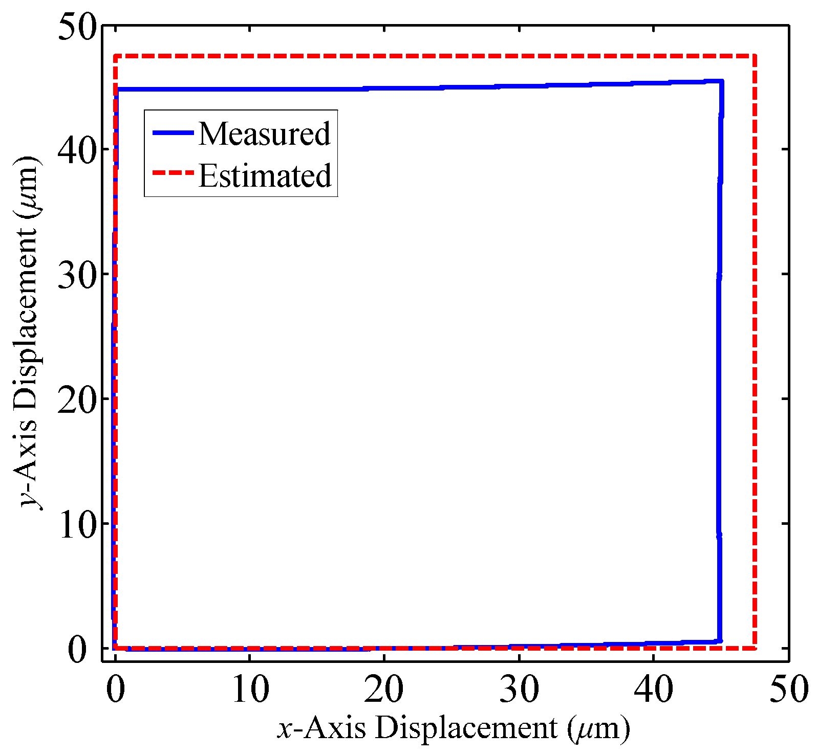
The workspace of the CPM was tested through running a square trajectory in the open-loop control. The experimental result and estimated workspace are given in
Figure 23. The measured workspace was 45.21 μm × 45.63 μm, which is a little smaller than the estimated result. The decreased motion of the CPM lies in the deformations of the joint surfaces between the parts connected by bolts.
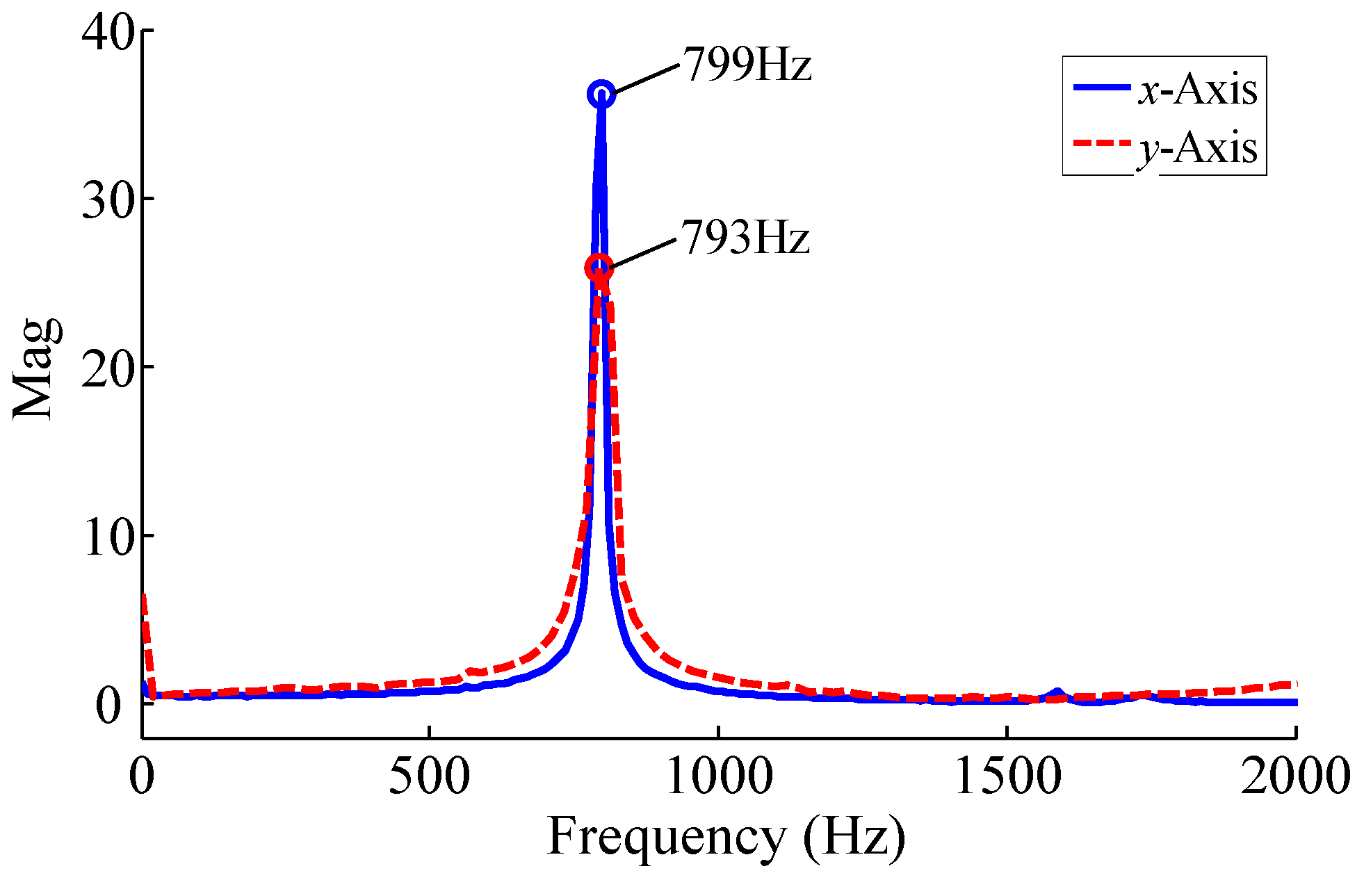
Then the natural frequency of the CPM was tested using the hammering method with the piezoelectric actuators dismantled. A modal hammer was utilized to apply impulse forces at the actuation points along the two axes, respectively. The dynamic response of the terminal platform was captured by the length gauges and the spectral analyses on the experimental results have been given in
Figure 24. The first two natural frequencies of the CPM were obtained as 793 Hz and 799 Hz, which are close to the simulated values.
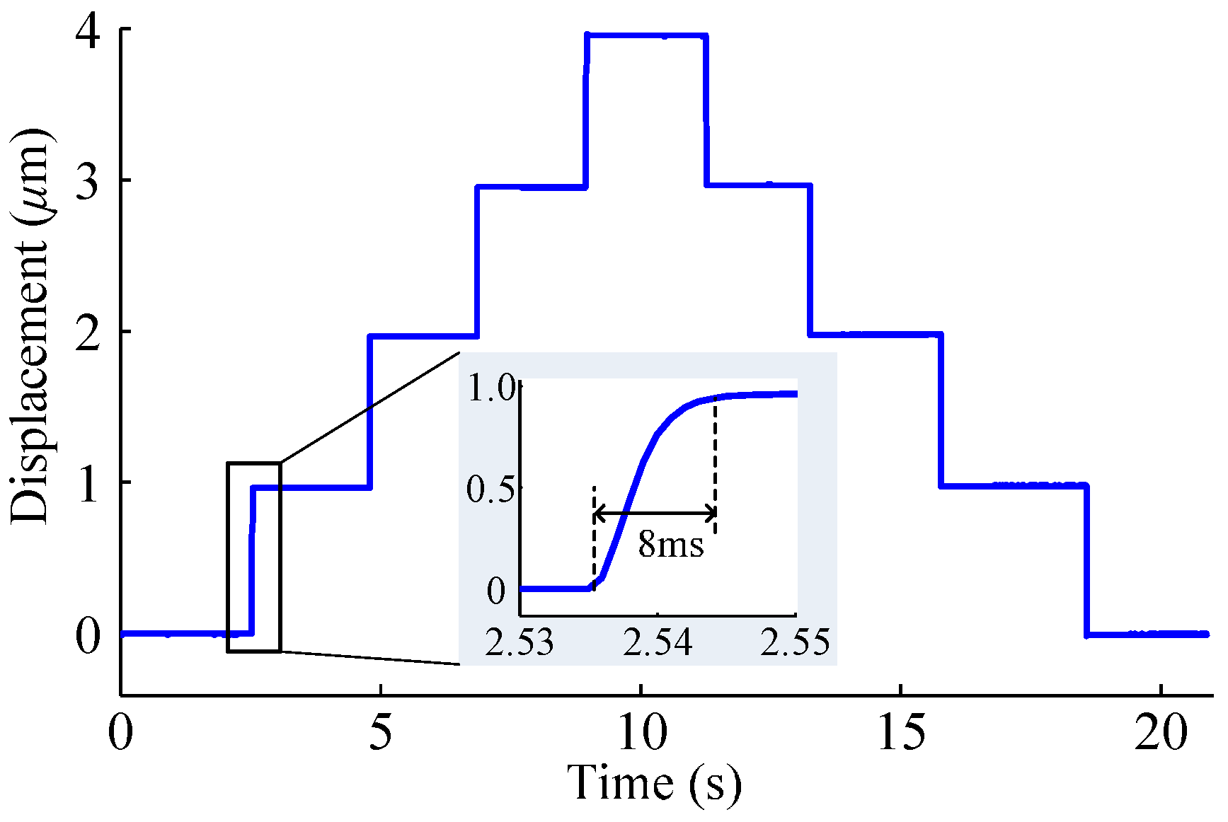
The step response of the CPM was tested where only the piezoelectric actuators adopted the closed-loop control. The result of the 1 μm step response test of the
x-axis is shown in
Figure 25. The rising time was 8 ms without overshoot. Similar results in the
y-axis were obtained, but are not shown herein. The results show that the CPM has a rapid response performance.
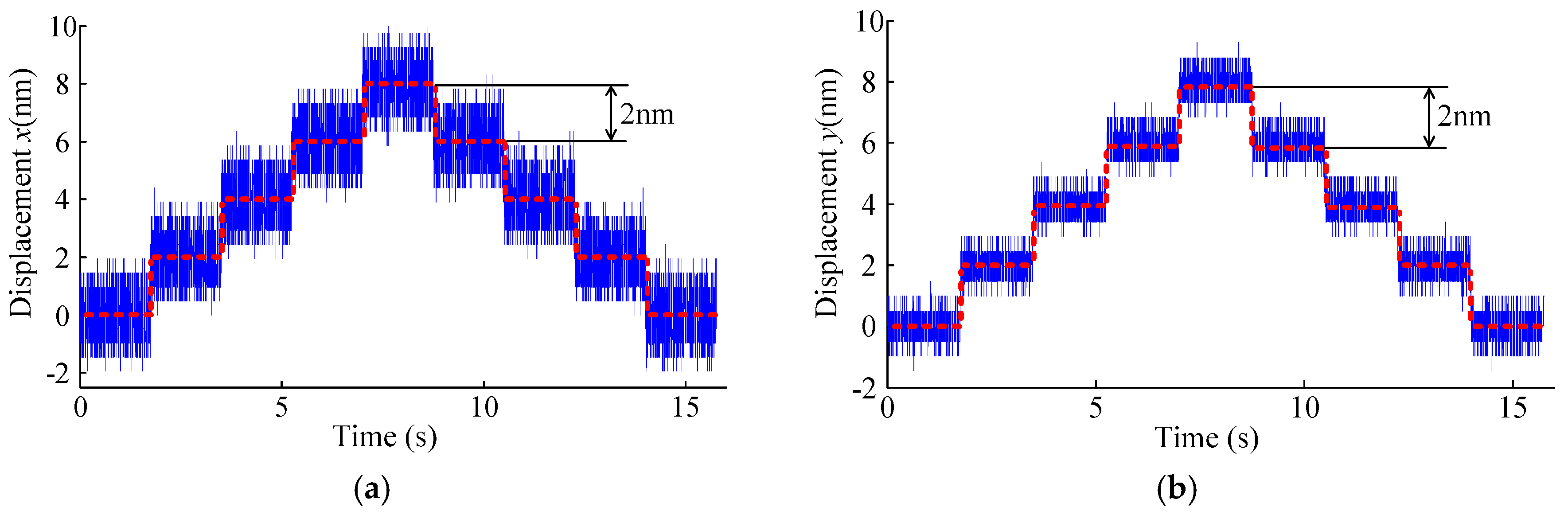
The positioning resolution of the CPM was tested in the closed-loop control. A consecutive-step positioning with a step size of 2 nm was carried out for each axis; results are shown in
Figure 26. The steps can be clearly identified, which indicates that the positioning resolution of the CPM is better than 2 nm. Moreover, the resolution can be improved by filtering the measurement noise.
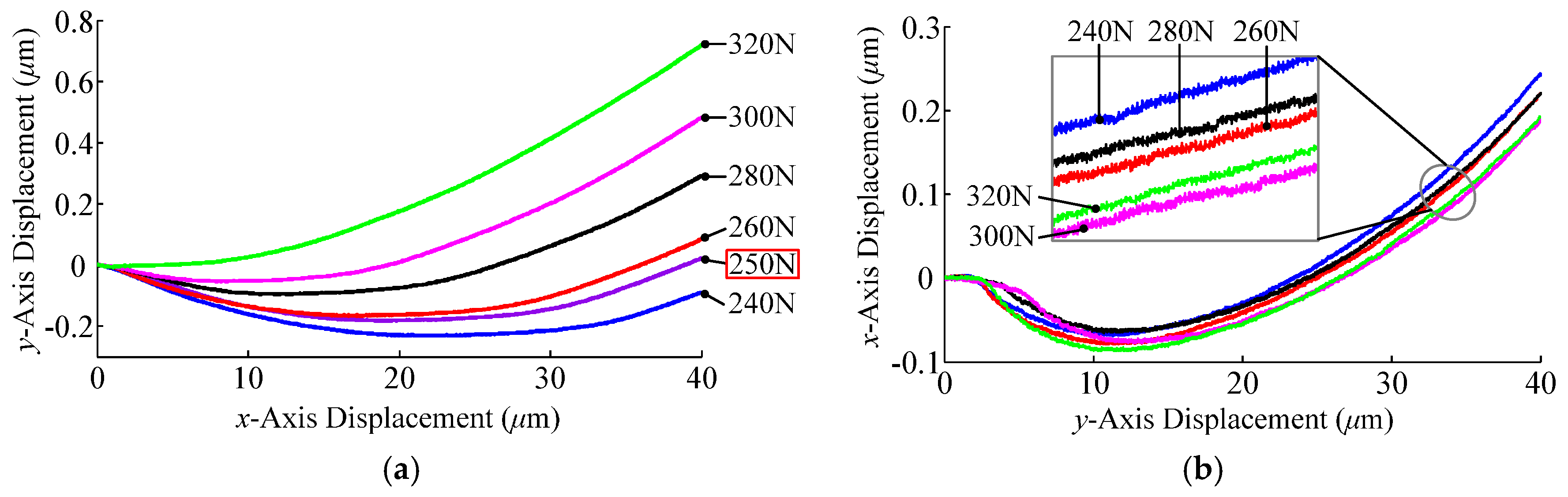
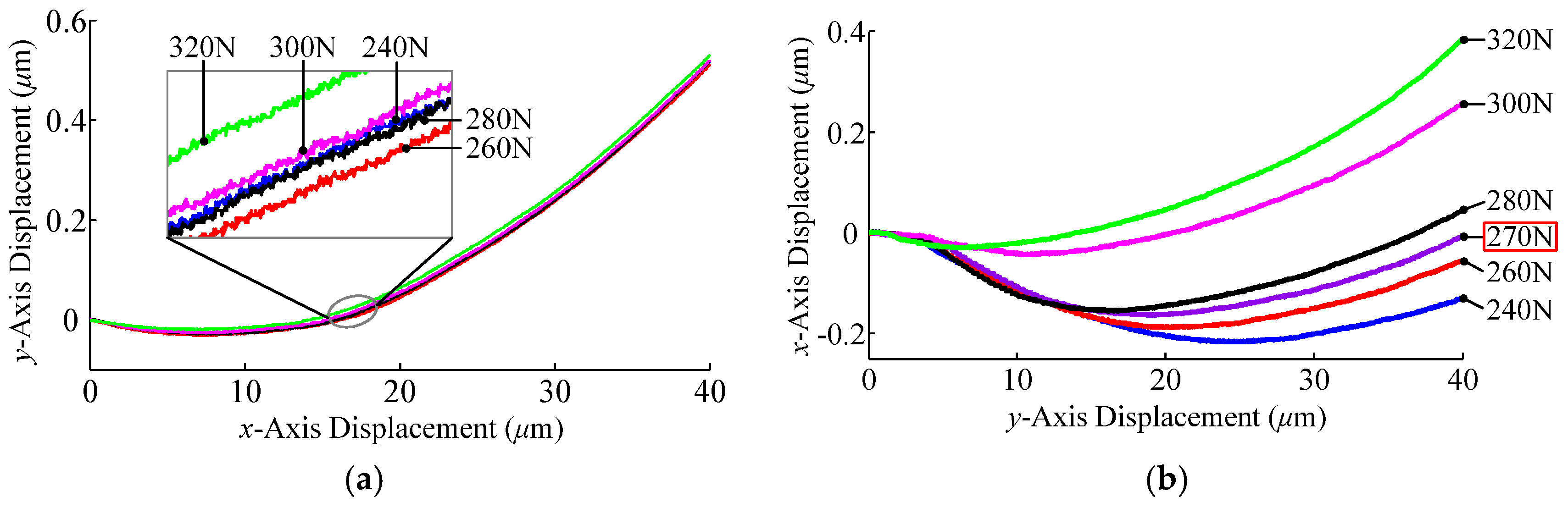
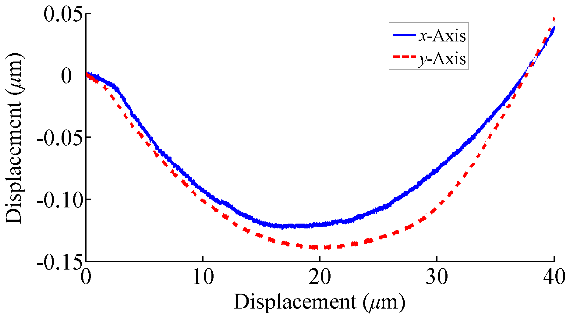
The output decoupling performance of the 2-DOF CPM was evaluated by actuating one axis and measuring the displacement output of the terminal platform along the other axis. The CPM’s maximum output motion ranges along the two axes were both set as 40 μm.
Figure 27 shows the coupled motions along the two axes when the preload force along the
x-axis changed from 240 N to 320 N while the preload force along the
y-axis remained unchanged. It can be seen that the coupling motions along the
y-axis varied significantly as the preload force changed. However, the variation of the coupling motions along the
x-axis was slight.
The coupling motions along the two axes when the preload force along the
y-axis changed from 240 N to 320 N are shown in
Figure 28, and a similar conclusion can be obtained.
The cases shown in
Figure 27 and
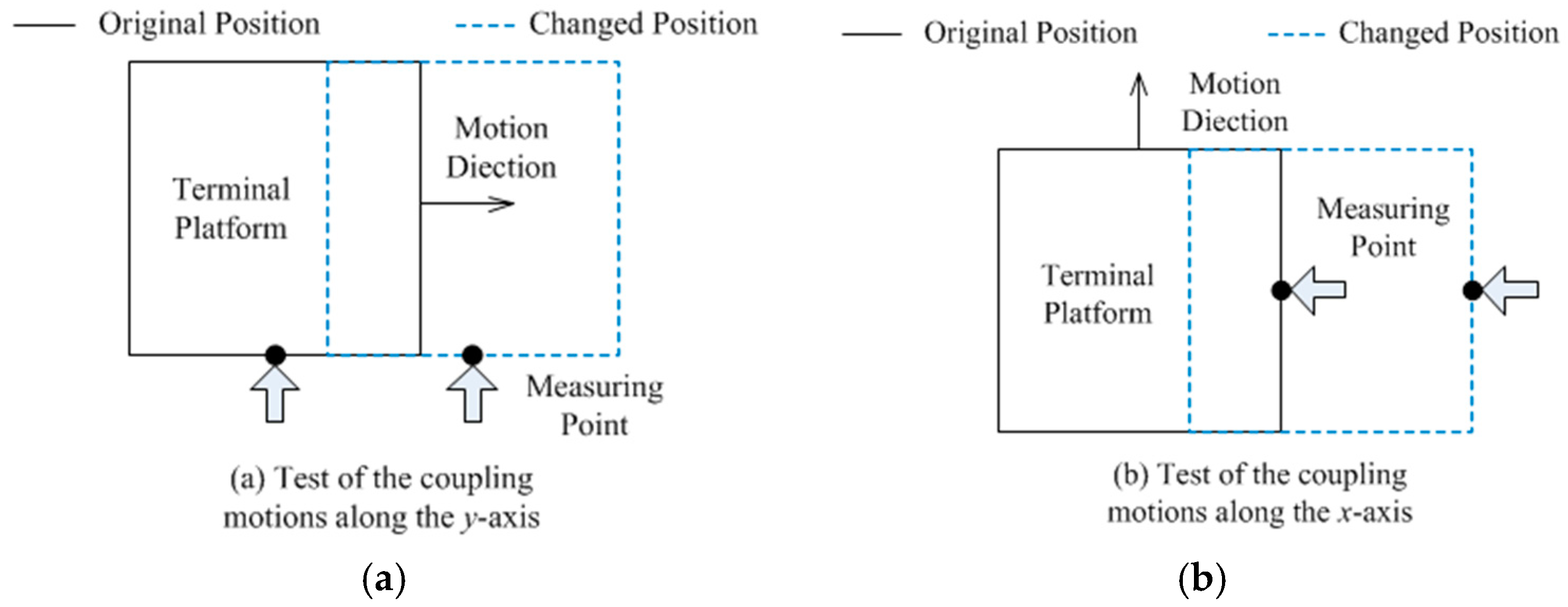
Figure 28 may come from manufacturing errors in the flatness of the measuring datum planes.
Figure 29 provides an explanation for the tested results of the coupling motions when the preload force along the
x-axis changes. It can be seen that the variation of the preload load force along the
x-axis will alter the initial measuring point on the terminal platform while testing the coupling motions along the
y-axis. The initial measuring point, however, remains the same when testing the coupling motions along the
x-axis. Therefore, the flatness of the measuring datum planes will influence the test of the coupling motions along the
y-axis when the preload force along the
x-axis varies.
Because the preload forces affect the coupling motions of the CPM, we can adjust the preload forces to minimize the cross-axis outputs. Through trial and error, the preload forces along the
x- and
y-axes, respectively, were chosen as 250 N and 270 N. The test for the two axes’ output coupling was performed and the results are shown in
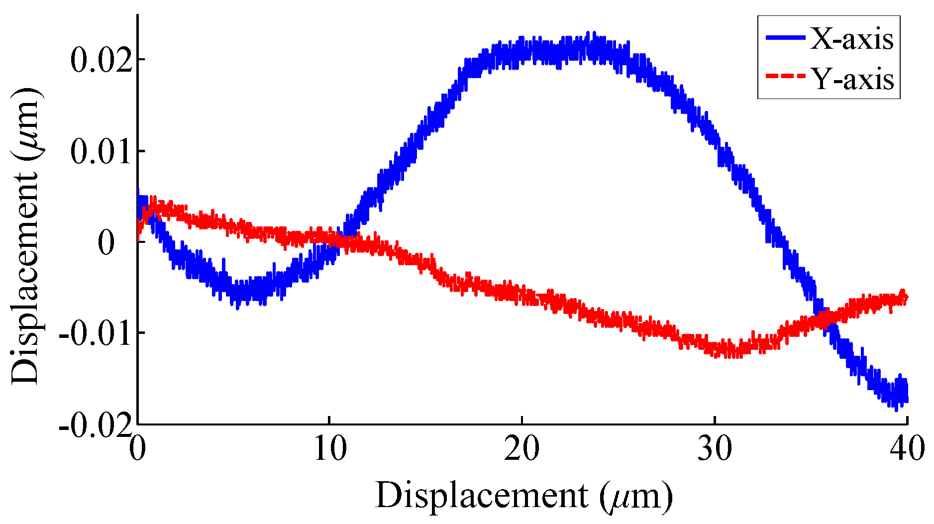
Figure 30. It can be seen that the maximum output couplings between the two axes are less than 0.5%.
Since the flatness of the measuring datum planes has a negative effect on the output decoupling performance of the CPM, the direct way of reducing its output coupling is to improve the manufacturing accuracy of the measuring base. The flatness of the measuring datum planes was improved to 1 μm. The preload forces along the two axes were set to 300 N. Then the output coupling of the CPM was re-evaluated and the results are given in
Figure 31. It shows that the cross-axis outputs of the CPM are significantly reduced and the maximum output couplings between the two axes are only 0.105% and 0.045%, respectively.
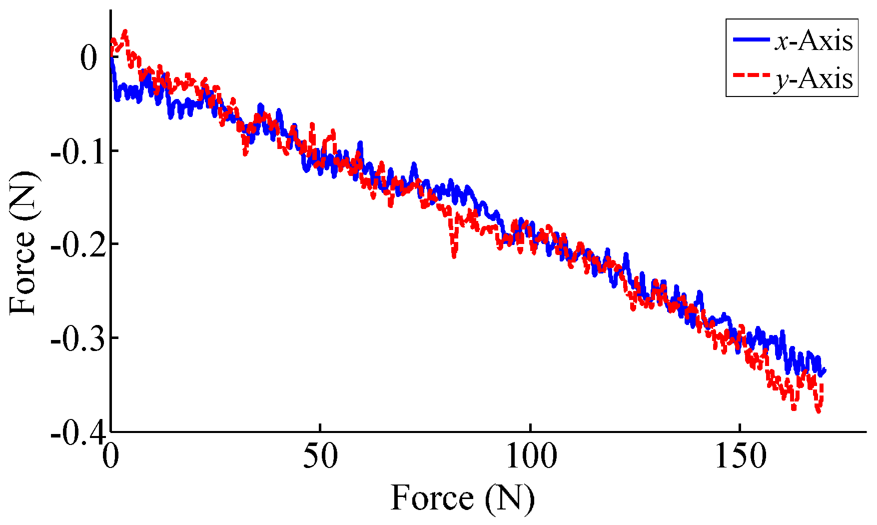
The actuation point deformation should be measured to evaluate the ICD of the CPM, which is impossible to be achieved experimentally in this prototype. To conquer this problem, we proposed utilizing the ratio of the axial deformations at the two actuation points to reflect the input coupling performance of the 2-DOF CPM. Because of the linear displacement–force relation as shown in
Figure 22, the changes of axial forces along the two axes were detected to indirectly evaluate the input coupling of the CPM. Tests were run on the variations of axial forces along the two axes when the
x- or
y-axis is actuated, shown in
Figure 32. The results show that when the CPM moves through the whole range along the
x-axis, the changes of the axial forces along the
x- and
y-axes are 169.4 N and 0.41 N, respectively. When the CPM moves through the whole range along the
x-axis, the changes of the axial forces along the
x- and
y-axes are 0.34 N and 170.2 N, respectively. The corresponding coupling ratios can be calculated as 0.24% and 0.20%, where the theoretical values calculated by Equation (28) are all 0.084%. The difference may lie in manufacturing and assembling errors. Regardless, this method provides a feasible way to evaluate the input coupling of the CPM and demonstrates this prototype’s excellent input decoupling performance.
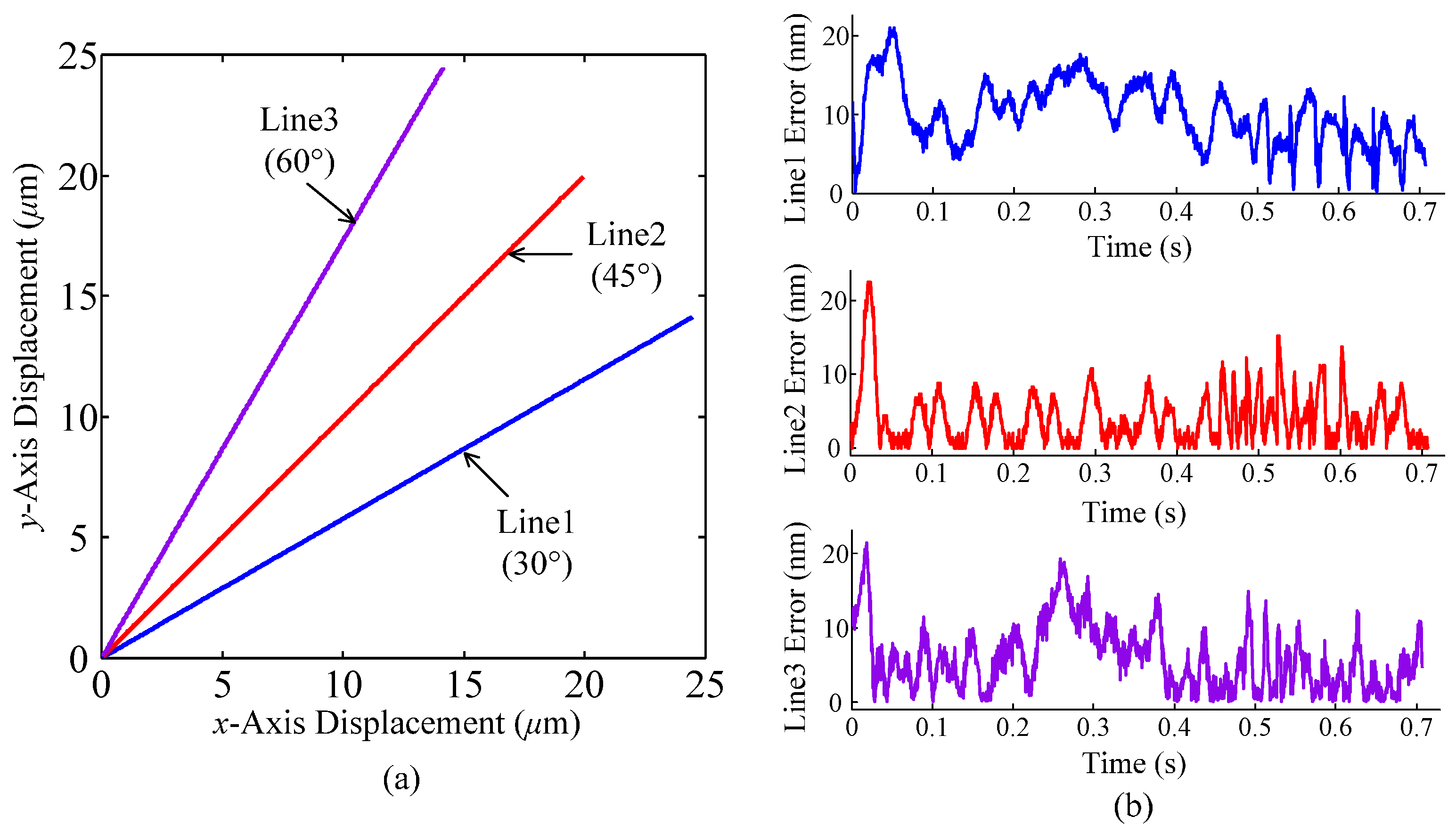
This study also evaluated the contour tracking of the CPM for 2-D trajectories, to reflect the two-axis cooperative tracking performance. To adequately verify the decoupling performances of the CPM, the actuators in the CPM were controlled independently without any additional kinematic calibration or compensation. A Proportion-Integration algorithm was utilized to realize the closed-loop control.
The 2-D tracking results for 30°, 45°, and 60° lines with a contouring velocity of 40 μm/s are shown in
Figure 33a, and the corresponding contouring errors have been plotted in
Figure 33b. The contouring error here is defined as the minimum distance between the actual position and desired trajectory along an orthogonal direction to the trajectory. The results show that the maximum contouring error is smaller than 25 nm.
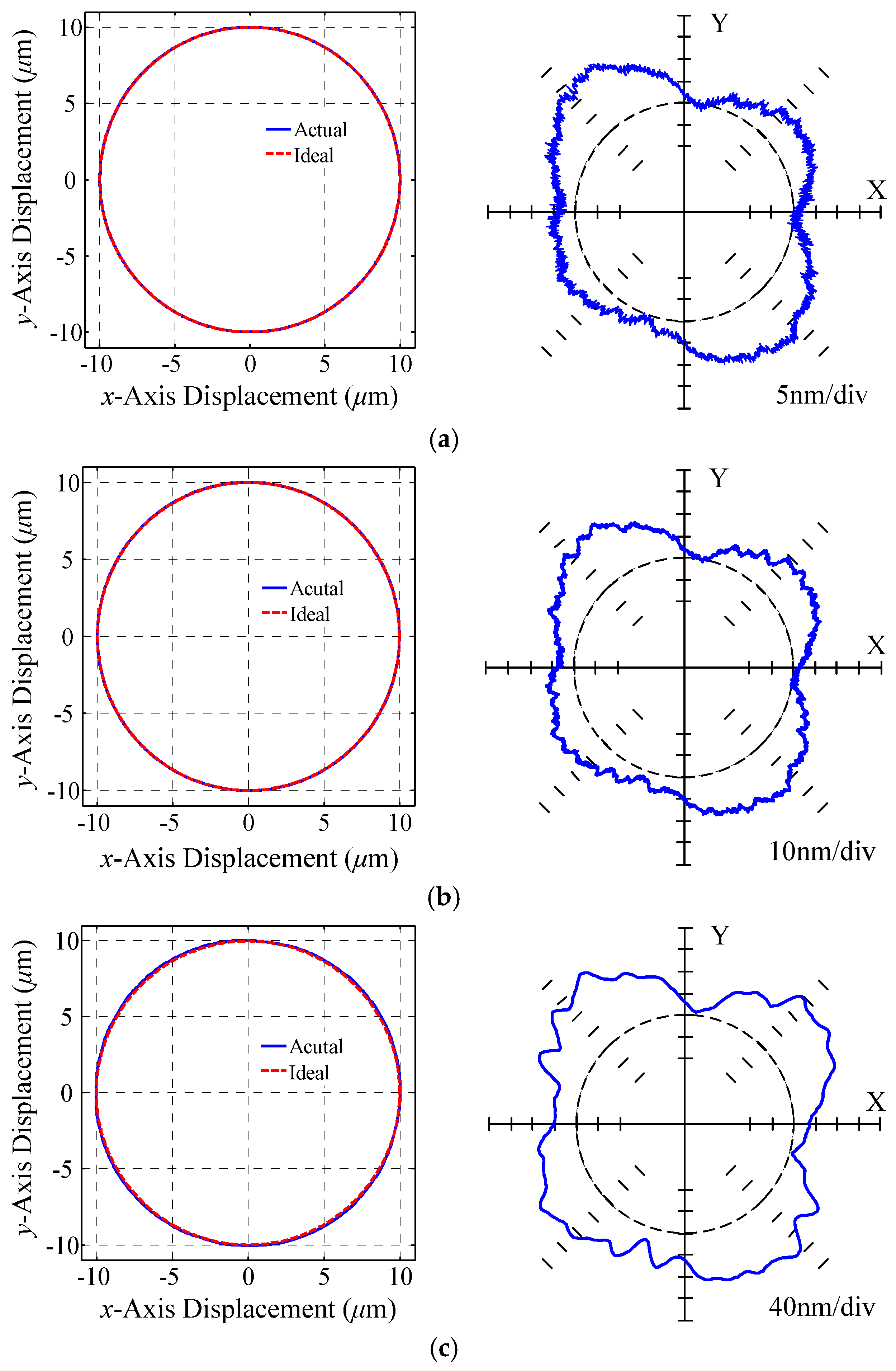
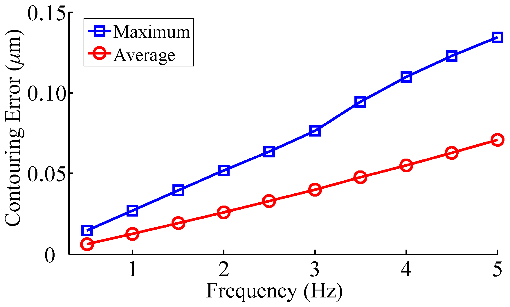
The experimental tests of circular contouring at different frequencies are shown in
Figure 34, where the radius of the circles is 10 μm. The measured circular trajectories are coincident with the ideal trajectory without elliptical distortion, which contributes to the identical dynamic characteristics and excellent decoupling performance of the two axes. To obtain a more intuitive comparison, the maximum and average contouring errors of the circular contour with different frequencies has been illustrated in
Figure 35. The results show that the contouring errors grow up as the frequency increases, and the maximum error is less than 150 nm. The contouring accuracy can be improved with the help of an advanced control strategy, which will be investigated in our future work.

