Article

Photon Beam Transport and Scientific Instruments at the European XFEL

European XFEL, Holzkoppel 4, 22869 Schenefeld, Germany
*
Author to whom correspondence should be addressed.
Appl. Sci. 2017, 7(6), 592; https://doi.org/10.3390/app7060592
Submission received: 1 May 2017 / Revised: 31 May 2017 / Accepted: 1 June 2017 / Published: 9 June 2017
(This article belongs to the Special Issue X-Ray Free-Electron Laser)

Abstract

:

Featured Application

This article describes the layout of the European XFEL, a soft and hard X-ray free-electron laser user facility starting operation in 2017. Emphasis is put on the photon beam systems, scientific applications and the instrumentation of the scientific instruments of the European XFEL.

Abstract

European XFEL is a free-electron laser (FEL) user facility providing soft and hard X-ray FEL radiation to initially six scientific instruments. Starting user operation in fall 2017 European XFEL will provide new research opportunities to users from science domains as diverse as physics, chemistry, geo- and planetary sciences, materials sciences or biology. The unique feature of European XFEL is the provision of high average brilliance in the soft and hard X-ray regime, combined with the pulse properties of FEL radiation of extreme peak intensities, femtosecond pulse duration and high degree of coherence. The high average brilliance is achieved through acceleration of up to 27,000 electron bunches per second by the super-conducting electron accelerator. Enabling the usage of this high average brilliance in user experiments is one of the major instrumentation drivers for European XFEL. The radiation generated by three FEL sources is distributed via long beam transport systems to the experiment hall where the scientific instruments are located side-by-side. The X-ray beam transport systems have been optimized to maintain the unique features of the FEL radiation which will be monitored using build-in photon diagnostics. The six scientific instruments are optimized for specific applications using soft or hard X-ray techniques and include integrated lasers, dedicated sample environment, large area high frame rate detector(s) and computing systems capable of processing large quantities of data.

1. Introduction

During the last decades, the development of X-ray light sources based on low emittance electron accelerators has enabled spectacular increases in the average and peak brilliances. Brilliance corresponds to the number of photons per phase space element of the emitted X-rays and is the parameter best describing the performance of these sources. Electron accelerators optimized for free-electron lasers (FEL) use low emittance injectors to create electron bunches, linear accelerators and electron beam optics to minimize the emittance growth during acceleration and transport, and bunch compression to generate ultrashort bunches. The resulting low emittance and high peak current of the electron bunches are the key performance parameters for these facilities. In undulator sections much longer than for synchrotron radiation sources, the electron bunches are transported with high precision and collimation to enable the self-amplified spontaneous emission (SASE) process leading to FEL gain and occurring in a single-pass of the electron bunch [1,2]. In the SASE process, the electron bunch typically undergoes a degradation of its properties and cannot be reused for another FEL source. It is instead dumped at the end of the beam transport. FELs therefore, in general, are single-user machines making their operation costly and the access to them much more limited than storage ring sources where electron bunches are circulated and are reused by several insertion devices. Since X-ray FEL radiation is generated by an intrinsically coherent SASE process it provides huge pulse energies of 10 mJ and possibly beyond, and pulse durations as short as single femtoseconds. These properties correspond to peak brilliances eight to nine orders of magnitude higher than obtained by storage ring sources. Exploiting this brilliance in FEL experiments allows embarking on yet impossible X-ray experiments that will lead to interesting and valuable scientific and technological applications.
Two technologies have been pursued to construct electron accelerators for FEL applications: warm, normal conducting machines and cold, super-conducting accelerators. The latter allowing acceleration of electron bunches at a much higher repetition rate, thereby boosting the average brilliance and enabling to distribute electron bunches to many FEL sources. The first short-wavelength FEL user facility starting user operation was FLASH at Deutsches-Elektronen-Synchrotron (DESY) in Hamburg (Germany), which uses super-conducting accelerator technology [3] and provides FEL radiation in the XUV and soft X-ray spectral region up to the water window [4]. In the following years, several normal conducting accelerator-based FELs started operation at SLAC National Accelerator Laboratory [5], ELETTRA [6], SPring-8 [7], and the Pohang Accelerator Laboratory (PAL) [8]. The SwissFEL facility at the Paul-Scherrer-Institute (PSI) [9] is nearing completion. The European XFEL [10,11] employs the same super-conducting accelerator technology [12] used for FLASH and is currently under commissioning for first user experiments in 2017. European XFEL enables the acceleration of up to 27,000 electron bunches per second with an electron energy of up to 17.5 GeV (compare Table 1) which are distributed to several FEL sources. Starting from 2019 European XFEL will operate a regular user program with initially six instruments continuously receiving X-ray beams. At SLAC currently a 4 GeV super-conducting accelerator is under construction for LCLS-II, based on the same technology used for FLASH and European XFEL plus enabling continuous wave (cw) acceleration [13].
The article is organized as follows: Following a description of the overall European XFEL facility, we shall first describe the photon beam transport and photon diagnostics systems, before introducing the individual science instruments. Finally, an outlook to future developments of the facility is provided.

2. Overview European XFEL

X-ray FEL radiation is characterized by its ultrashort pulse duration, high pulse energies and a high degree of coherence. Scientific applications of soft and hard X-ray FEL radiation make use of these properties, in particular in the investigation of ultrafast processes in atoms, ions, simple and very complex molecules, clusters or condensed matter. The high pulse energies allow the collection of meaningful data sets from single pulses, thereby enabling the study of non-reversible processes. Coherence properties are exploited in imaging techniques that aim to obtain atomic spatial resolution for weakly scattering systems, in part combined with a corresponding temporal resolution [16]. Finally, the very high X-ray pulse energies, which combined with ultrashort pulse durations correspond to very high peak powers of up to several tens of GW, promise to enable access to new information of excited solids through non-linear X-ray scattering [17].
There are several classes of these experiments requiring not only a high peak brilliance, but also high average brilliance. Here European XFEL has a clear advantage compared to other X-ray FEL facilities. Examples comprise studies of ultra-dilute systems, very small cross-section processes, non-linear X-ray processes, or particle-particle/particle-X-ray coincidence spectroscopy experiments. Furthermore it is possible to use subsequent X-ray pulses to probe equilibrium dynamics at frequencies up to 4.5 MHz, and beyond [18].
To enable the use of the highest repetition rates in a pulse-resolved (non-integrating) manner has been the biggest instrumentation challenge for European XFEL. Such a mode of operation requires that diagnostic and X-ray detection systems operate at repetition rates of up to 4.5 MHz. In addition, optical lasers used to excite samples in a well-controlled manner and sample injections systems need to accommodate these high event rates. The development of this non-standard high repetition rate instrumentation is one key expertise of European XFEL and its partners.

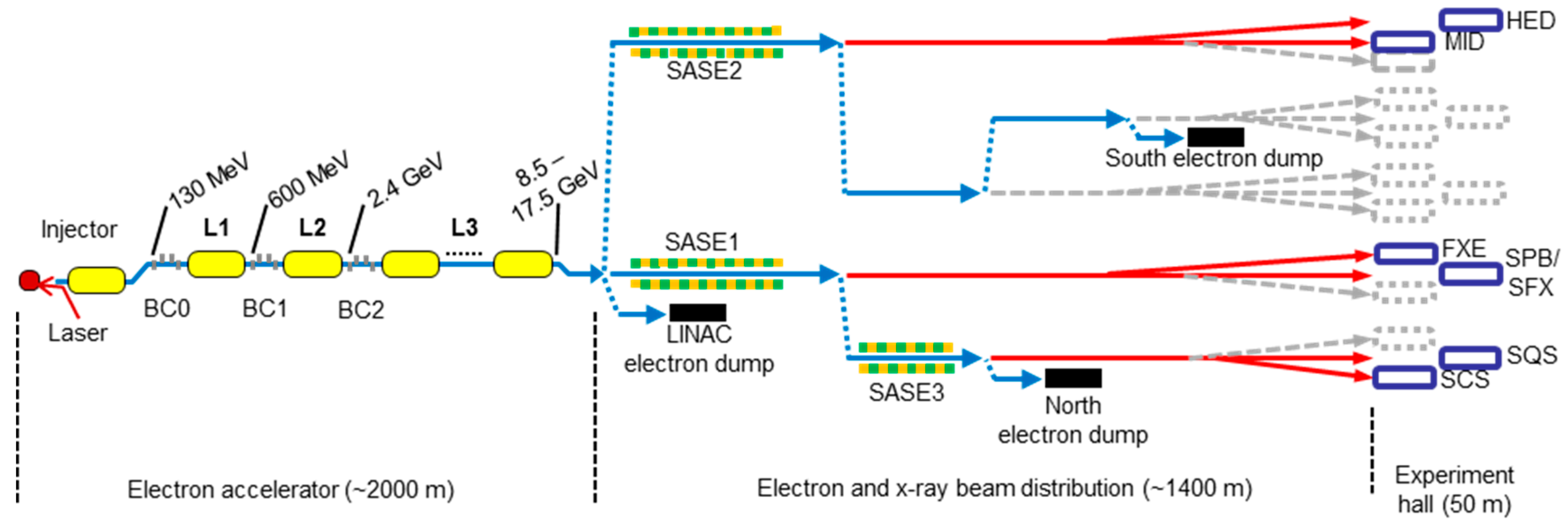
2.1. Layout of the European XFEL Facility

The European XFEL facility consists principally of three sections. The first section includes the superconducting low emittance 17.5 GeV electron accelerator and the distribution of electron bunches to two beam lines comprising the FEL undulator sources. The electron beam transport is designed to accommodate up to five FEL sources. Each FEL source has a dedicated photon beam transport section to transport, steer, focus, and diagnose the X-ray FEL beams prior to their entry to the experiment hall. Mirrors in the photon beam transports will direct the X-ray FEL beam to one of the scientific instruments located at the respective FEL source. The third section is the experiment hall in which the scientific instruments are located and where the experiment program is run. In its first installment, only three FEL sources are constructed each leading to two scientific instruments. Figure 1 provides an overview of the European XFEL facility. Completion of the facility with five FEL sources and up to fifteen scientific instruments is expected to take place in the years following start of user operation.
The layout of European XFEL is governed by a few basic conditions. First, the goal to reach FEL radiation exceeding 20 keV with high pulse energies and outstanding coherence properties has been driving the definition of the maximum electron energy to be 17.5 GeV. Using an acceleration gradient of 23.6 MeV/m this alone results in a length of nearly 1000 m for electron acceleration. A second condition was to expand the highly collimated FEL beam to a size of order 1 mm, requiring with divergences of order of 1 µrad for hard X-rays another approximately 1000 m free-space transport. This is accompanied by another requirement of achieving lateral separations on the order of 17 m for the beam lines of the different FEL sources when arriving at the experiment hall.
The facility is located in the western part of the Metropolitan area of Hamburg, reaching from the DESY campus in Hamburg Bahrenfeld to the town of Schenefeld, Schleswig-Holstein. Located in a partly inhabited area, the facility had to be built in underground tunnels, fully immersed in the ground water in this location. Access to tunnels is enabled by shaft buildings at the start and end of each tunnel, and access to the experiment hall is provided from the office and laboratory building build on top of this hall.

2.2. The Super-Conducting Electron Accelerator

The European XFEL accelerator has the task of providing electron bunches for the FEL process. It consists of a photo-injector, the main linac and the different beam line sections. In the 43 m long photo-injector section [19,20], electron bunches are generated by means of the photoelectric effect from a CsTe cathode. The photocathode is located inside a normal-conducting cavity to immediately accelerate the electrons to 6 MeV before injection into the first super-conducting accelerator module. This module is directly followed by a super-conducting 3.9 GHz acceleration module needed to linearize the longitudinal phase of accelerated electrons. At 130 MeV the electrons enter a diagnostic section enabling the measurement of the phase space properties of individual electron bunches in the bunch train and even of slices of these bunches. At the end of the injector an electron beam dump allows standalone operation of the injector over its full parameter range, such that commissioning and further development can be performed independently of the operation of the main linac. Electron extraction from the cathode is achieved by frequency-quadrupled 257 nm laser pulses supplied by a dedicated Nd:YLF photo-injector laser. The laser is synchronized to the accelerator radio-frequency and delivers a time pattern corresponding to the burst mode repetition rate of electron bunch delivery. The photo-injector performance determines the smallest obtainable emittance of the entire accelerator and its design has been optimized in this regard. Space charge driven emittance growth is the most important limiting effect and is minimized by relatively long laser pulses (up to 20 ps) and very high acceleration gradients of up to 50–60 MV/m at the cathode. Furthermore, the spatial and temporal profile of the laser pulse ideally has a top-hat-like shape when hitting the cathode. The operation with electron bunch charges from 0.02 to 1.0 nC at different emittances and enabling different bunch durations is foreseen. Initial commissioning of the injector was concluded in summer 2016 [21].
The main linac accelerates the electrons to a final energy of up to 17.5 GeV by means of 96 accelerator modules operated at 2.2 K, built by an international collaboration for European XFEL based on the TESLA design [14]. Each module is 12 m long, weighs eight tons and comprises eight nine-cell Nb cavities. A total of 768 couplers provide the radio-frequency (RF) fields generated by 24 RF stations. The accelerator is operated in a 10 Hz pulsed RF mode (see Figure 2) for a maximum beam power of 500 kW, exceeding by far the power that can be reached by any normal conducting machine. The design gradient is 23.6 MV/m and the final installation considers the actual performance of each accelerator module by tuning the RF distribution system. The injector and the three linac sections L1, L2 and L3 are separated by three electron bunch compressors BC0, BC1 and BC2. These are used to compress the electron bunches in steps from their initial approximately 20 ps duration to as short as a few fs, hence reaching the design peak current of 5 kA, depending on the bunch charge. The electron energy at the end of L2 is 2.4 GeV and will be kept constant during operation in order to optimize the performance of the accelerator. Dedicated diagnostics sections for the measurement of integrated and slice bunch parameters are located after compressors BC1 and BC3. Cool-down of the linac was started end of 2016 and commissioning with electron beam commenced in 2017 [22,23].
The last section comprises a total of approximately 3 km of electron beam transport systems and starts with a collimation section removing halo and electrons at non-matching energies, i.e., dark current, from the beam. Downstream of this section electron bunches are distributed to either one of the two beam lines with the FEL undulators, denoted the North and South electron branches, or to a dump beam line. Distribution between the two branch lines is performed by a precise flat top kicker magnet with fast falling edge operating at 10 Hz to switch once during each bunch train. Likewise a dedicated portion of the 600 µs bunch train is first kicked to the South branch line. After a switching time of approximately 20 µs electrons continue without kicking into the North branch line. An additional fast kicker can operate at up to 4.5 MHz and is used to deflect single bunches to the dump beam line. It is used to, e.g., generate the time window needed for switching between south and north branch and furthermore enables a free choice of the bunch pattern delivered to the two FEL beam lines while the accelerator is operated at constant loading. At the end of each electron beam line a solid state dump is capable of absorbing up to 300 kW of beam power. In case the accelerator is operated at full beam power, electrons will be distributed over more than one dump thereby limiting the absorbed power. In the beam transport section of the accelerator many important electron diagnostics systems are located. They measure beam position with µm accuracy, arrival time of bunches relative to a precise laser synchronization system with down to a few fs accuracy, and electron energy in dispersive sections to a level better than 10−4. The long pulse trains allow using an initial portion of the train for intra-train feedback scheme, thereby enabling a higher stability and performance of the electron beam delivery in the remaining portion of the train delivered to the two branch lines.

2.3. The FEL Undulator Sources

The initially three FEL undulator sources denoted SASE1, SASE2 and SASE3 will provide FEL radiation ranging from the carbon K-edge to very hard X-rays for user experiments. SASE1 and SASE2 serve the hard X-ray regime from approximately 3 to 25 keV in the first harmonic. SASE3 produces soft X-rays from approximately 250 eV to 3 keV. These ranges are achieved by a combination of electron energy set points and gap tuning (see Table 2). The lengths of the FEL undulators have been determined after simulation of the saturation length for the highest photon energy at the largest considered electron beam emittance. All FELs are therefore much longer than the saturation length in the middle of the tuning range, around 10 keV (SASE1 and SASE2) or up to 1 keV (SASE3), which allows for special modes of operation, e.g., the implementation of self-seeding. In addition, each FEL has additional space before and after the device for optional extensions, e.g., for laser-driven beam manipulation or so-called afterburners.
All FELs are segmented into 5 m long planar undulators and 1.1 m long intersections. Undulators are equipped with permanent hybrid NdFeB magnet technology for a minimum magnetic gap of 10 mm allowing the use of aluminum vacuum chambers with an inner opening of 8.8 mm for the electron beam. Out of vacuum magnetic structures were chosen to minimize radiation damage of the magnets, but also to reduce resistive wall wake fields. The intersections carry a quadrupole for electron beam focusing, a phase shifter for matching the radiation field and the micro-bunched electron beam, an electron beam position monitor, and vacuum devices. All parts for the total 91 undulator segments have been produced and assembled by industry. Magnetic tuning was performed by the European XFEL undulator group using the pole-height tuning technique [25].
The FEL source properties depend on a large number of parameters, not only of the FEL undulators, but also the electron beam properties, e.g., peak current, emittance, or energy spread. Table 3 shows simulation results for the saturation point for a selection of photon energies and electron beam parameters. The full set of properties can be found in refs. [26,27]. In practice, FELs are often operated well beyond saturation thereby boosting the emitted pulse energies but also sacrificing some of the other properties.

2.4. The Experiment Hall and Ancillary Instrumentation

The experiment hall has a size of 50 m along the beam direction and 90 m across to install five beam line areas. The tunnels housing the X-ray beam transports enter with a separation of approximately 17 m. For each of the five beam line areas installation of up to three scientific instruments is considered with an X-ray beam separation of 1.4 m at the entrance to the hall. Each beam line area includes dedicated enclosures for X-ray optics, X-ray experiment, controlling the experiment, the pump-probe laser system, instrument laser hutches, and in some cases also preparatory labs. Control and data acquisition electronics are generally placed in separate rack rooms located on-top of the beam lines for fire protection purposes. Here also most of the air-conditioning systems are located, used to stabilize dedicated temperature zones to ±0.1 °C while special care has been taken to avoid vibrations. The hall is connected via stairs and elevators to the laboratory and office floors in the building above. In the ground floor in total ~2500 m2 is available for laboratories, comprising rooms for sample preparation and characterization, chemistry and biochemistry laboratories. Furthermore, cleanrooms for optics, detector and vacuum part assembly and testing and several laser labs for research and development are found here.

2.4.1. Large Area Detectors for European XFEL

Already in 2006 European XFEL launched a significant program for the development of large area detectors for FEL experiments, since it was clear that the requirements to detectors for FEL experiments in general and European XFEL specifically could not be fulfilled by existing devices [28]. General requirements include an integrating operation mode, enabling the detection of several X-ray photons per pixel and per pulse, very low noise, enabling to detect single X-ray photons, and a high dynamic range, enabling to count 104 or more X-ray photons in a single pixel. Specific requirements for European XFEL include the need for frame rates of up to 4.5 MHz, in order to be compatible with X-ray pulse delivery within the pulse train structure (compare Figure 2), high throughput, to collect as many images as possible per unit time, and radiation hardness. More recently, the possibility of vetoing specific events was added as a requirement. Three large projects were selected and are pursued together with external partners. Laboratory infrastructure, in particular for detector calibration and characterization, has been designed and is operated by the European XFEL detector group [29]. In addition, a few smaller projects consisted in modifying existing cameras, mostly designed for 10 Hz operation, and in upgrading the Gotthard one-dimensional strip detector [30] to 4.5 MHz repetition rate. In the following the three large area detector projects are described briefly.
The Adaptive Gain Integrated Pixel Detector (AGIPD) is developed by a consortium led by DESY [31]. The main features of this detector are 200 × 200 µm2 pixels, dynamic gain switching with 3 stages, a dynamic range of ~104 at 12 keV, single photon detection (6σ) above 7 keV, in-vacuum operation, the capability of storing up to 352 images within the 600 µs pulse train, and to read out these data in-between pulse trains. As sensor material 500 µm thick Si is used. Two 1 Mpixel AGIPD devices constitute the primary 2D detectors at the SPB/SFX and MID instruments. A 4 Mpixel device is under development as part of the SFX User Consortium, as is a 1 Mpixel device with GaAs sensor for the HIBEF User Consortium.
The Large Pixel Detector (LPD) is developed by a consortium led by STFC [32]. The main features of this detector are 500 × 500 µm2 pixels, three amplifiers with different gain per pixel, a dynamic range of up to ~105 at 12 keV, single photon detection (3σ) above ~12 keV, the capability of storing up to 512 images within the 600 µs pulse train, and to read out these data in-between pulse trains. As sensor material, 500 µm thick Si is used. A 1 Mpixel LPD device will be employed at the FXE instrument, primarily for liquid scattering experiments.
The DepFET Sensor with Signal Compression (DSSC) detector is developed by a consortium initially led by the Max-Planck-Society (MPG) [33]. The main features of this detector are hexagonal 236 µm diameter pixels, a non-linear gain, a dynamic range of ~6 × 10³ at 1 keV, single photon detection (5σ) above 0.7 keV, in-vacuum operation, the capability of storing up to 800 images within the 600 µs pulse train, and to transfer up to 640 frames in-between pulse trains. The highest frame rate of the DSSC detector therefore is 6.4 kHz. As sensor material 300 µm thick Si is used. One 1 Mpixel DSSC device is considered as the primary 2D detector for the SCS and SQS instruments. In a first phase, a simplified detector with 1 Mpixel Si drift diodes with reduced performance will be available for experiments.

2.4.2. Optical Lasers for European XFEL

The usage of synchronized optical laser pulses is foreseen at all scientific instruments and opens various possibilities for time-resolved pump-probe studies and laser-controlled manipulation of electronic relaxation and excitation processes. A dedicated development has been initiated to meet the requirements of delivering 800 nm radiation, 10–100 fs pulse duration, 0.1–4.5 MHz selectable pulse delivery and 0.1–1 mJ pulse energy. After the successful completion of a first design phase [34] the implementation of three pump-probe burst-mode optical (PP) lasers systems was started, each serving one beam line area. The final amplification of the laser pulses employs the Non-collinear Optical Parametric Amplifier (NOPA) scheme. Three NOPA stages allow providing highest pulse energies at reduced repetition rate, 3.25 mJ for 0.1 MHz, and reduced pulse energies at highest repetition rate, 0.08 mJ at 4.5 MHz. A Pockels cell and polarizer before the NOPA amplifiers enable picking of arbitrary pump pulse sequences from the amplified burst at frequencies up to 4.5 MHz. An additional output delivers 1030 nm pulses with energies up to 40 mJ at 0.1 MHz and duration of 400 ps or 800 fs (compressed). Full performance of the system has been demonstrated recently [35]. In order to synchronize the delivery of optical laser and X-ray pulses, RF and optical lasers a laser-based synchronization system [36] is employed with the goal of reaching an accuracy better than 20 fs rms [37].
The PP lasers are placed in dedicated laser rooms at each beam line. Laser beams are transported to dedicated instrument laser hutches (ILH) adjacent to the X-ray experiment areas. The separation from the X-ray hutch provides the possibility to work on these systems without disturbing the X-ray program. In the ILHs, e.g., delay stages, frequency conversion optics, and laser diagnostics are placed. Laser pulses are transported in a time stretched mode and final compression occurs close to the experiment location. Particular care needs to be taken with respect to the dispersion management of the optical laser pulses in order to achieve the shortest pulse duration.

2.5. The User Program

The European XFEL is conceived as a user facility with the main emphasis of providing excellent conditions for FEL research with soft and hard X-rays. To reach this goal an accelerator operation of approximately 5600 h annually is foreseen to provide 4000 h of user operation, 800 h for accelerator and another 800 h for X-ray systems maintenance, research and development. Operation will be continuous for several weeks with interruptions during two workdays, mainly for setup changes, maintenance, and tuning for the next experiments. With initially two scientific instruments per FEL source each of them schedules ~2000 h per year for users. In regular operation this should allow for >200 user experiments annually, thereby significantly increasing the European and worldwide accessibility of FEL experiments. User experiments will be selected by peer-review using scientific excellence as criterion given that technical feasibility and safety requirements are fulfilled. User groups will be supported by the instrument staff and the scientific support groups in preparing and executing the experiment and analyzing the data. Due to the complexity of FEL experiments, often requiring expertise in X-rays, optical lasers, sample delivery, detectors and data analysis, it is the goal to provide these systems to the users, thereby facilitating the use of European XFEL and lowering the entry level to FEL experiments. During experiments scientific staff of European XFEL will continuously support user groups and ensure that the various sub-systems are functional.

2.6. European XFEL Governance and Organization

The operation of the overall European XFEL facility is entrusted to the European XFEL GmbH, based on an intergovernmental agreement between the participating countries Denmark, France, Germany, Hungary, Italy, Poland, Russia, Slovakia, Spain, Sweden, Switzerland, and the United Kingdom. The largest contributors are Germany with 58% and Russia with 27% of the total construction cost. Each participating country determines a legal entity to hold their shares and to represent the country in the Council, the superior governance board of European XFEL. The construction costs of the facility can be sub-divided into the three major areas: civil construction, accelerator complex, and X-ray systems with shares of roughly 30:50:20. About 50% of the construction cost was provided through in-kind contributions by the participating countries. The annual costs for operation are shared amongst the participating countries initially according to the participation in the construction period. Starting in 2023, 50% of the annual operation costs will be distributed according to real usage of the facility by research groups from the participating countries, calculated using a three-year average.
The construction, commissioning and operation of the superconducting accelerator and its ancillary systems depend on the expertise residing at DESY, a major accelerator and photon science laboratory located in Hamburg, Germany. During the construction phase DESY led the international Accelerator Consortium that designed, built, and commissioned the accelerator. European XFEL staff has been responsible for the X-ray systems and ancillary instrumentation, including the undulators. For the operation phase European XFEL and DESY have concluded an agreement according to which DESY provides the personnel and expertise to operate and further develop the accelerator. European XFEL takes the responsibility for the X-ray systems and the user program of the facility.

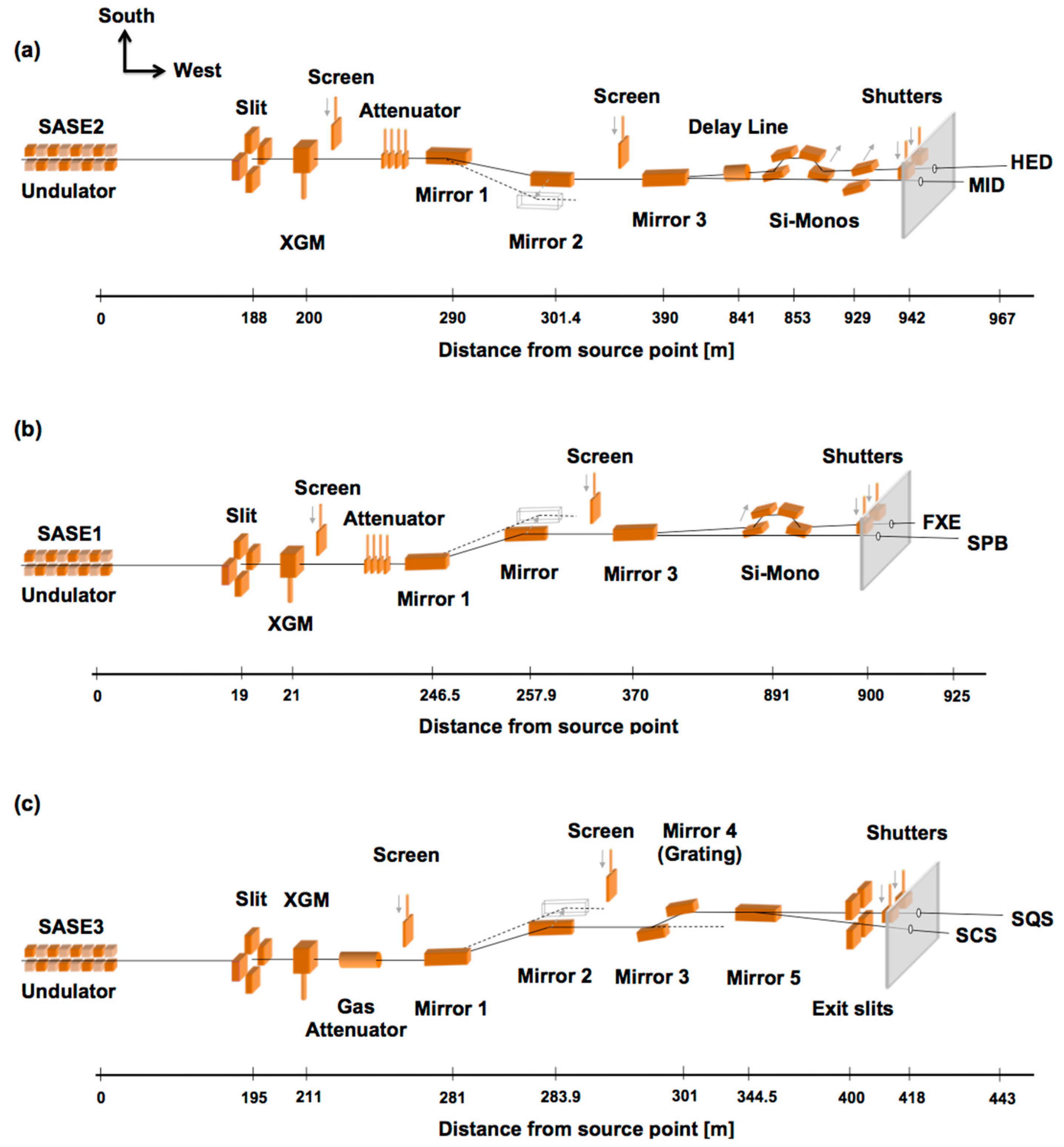
3. X-ray Photon Beam Transports

The X-ray optical systems that transport X-ray photons from the undulators to the experiment hall are located in long underground tunnels. From the source point of FEL radiation located within the last segments of the FEL undulators to the scientific instruments in the experiment hall these beam transport paths are up to 1 km long [38,39]. The key optical elements of each transport system are three mirrors: Mirrors “1” and “2” create a horizontal offset of the X-ray FEL beam. This offset prevents unwanted background radiation, consisting of Bremsstrahlung and high-energy spontaneous radiation also produced in the long FEL undulator, to be transported into the experiment areas. The spontaneous radiation has a critical energy of typically 200 keV and is not reflected by the offset mirrors, but is rather absorbed by the first mirror or transmitted and then stopped by a massive tungsten beam stop. Only the desired X-ray FEL photons in the energy ranges of 3–25 keV (SASE1 and SASE2) and 0.25–3 keV (SASE3) can pass the offset mirror chicane. Mirror “3” (distribution mirror) can be optionally inserted to reflect the photons to the HED, FXE, or SCS instruments, while the undeflected beam passes to the MID, SPB, and SQS instruments, respectively (compare Figure 3). In the case of the FXE, MID and HED instruments, multi-bounce crystal monochromators (optional) are integrated in the beam transport. For SASE3 a grating monochromator has been integrated that can be used by the SCS and SQS instruments at this FEL source. The beam transport layout includes for each of the systems the possibility of integrating a third beamline to a third instrument. Such an extension is currently in preparation at SASE3.
The distance from the source point to the first mirror is between ~245 and 290 m, which is enough to expand the beam to a size filling the about 1 m long mirrors under grazing incidence angle and thereby reducing damage and heat load effects. In order to handle the demanding power densities, a surface coating with boron carbide is applied on the single crystalline silicon mirrors. A liquid indium gallium eutectic film, which is in contact with water-cooled copper blades, is used to remove excess heat from all mirrors of the beam transport system. Because the X-ray FEL radiation is close to the diffraction limit, its divergence is roughly proportional to the photon wavelength. To utilize the full length of the offset mirrors for all photon energies, their reflection angle can be varied from 1.1–3.6 mrad for the hard X-ray beam transports and from 6–20 mrad for SASE3. The reflection angles define the energy cut-off and, thereby, the transport of higher harmonic radiation, too. The distribution mirror operates at a fixed angle, which is defined by the distance from the mirror to the experiment hall and the lateral distance (1.4 m) between the shutters of instruments operating at the same SASE beamline. To avoid over-illumination of the distribution mirror, the second offset mirror is bendable and can slightly focus the beam towards the distribution mirror. Alternatively, Be Compound Refracting Lenses (CRL) positioned upstream of the offset mirrors of the SASE1 and SASE2 beam transports can be used to collimate the beam or to produce a similar confocal beam situation with an intermediate focus behind the distribution mirror.
The most crucial requirement to the X-ray mirrors is preservation of the almost perfect wave front created by the lasing process [40]. Source properties and source-to-mirror distances at the European XFEL lead to requirements of about 2 nm peak-to-valley shape error for all mirrors of the beam transport systems, corresponding to roughly 50 nrad rms in slope error. The mirrors were manufactured in Japan and Germany by deterministic polishing techniques, where material is iteratively removed on atomic length scales according to a very precise metrology map of the mirror before each polishing step.
One important constraint of X-ray beam optics at an X-ray FEL is the so-called single-pulse damage. Because a large number of photons (corresponding to pulse energies of the order of mJ per pulse) arrive within 10–100 fs, thermal transport does not remove any heat during the pulse, even for excellent heat conductors like copper or diamond. For focused beam conditions (typically smaller than 50 µm diameter), most materials will vaporize on an ultrafast time scale due to the absorption of energy from a single X-ray FEL pulse within the X-ray penetration depth. More resistant materials are the ones with low atomic number where the absorption per atom is lower. Most components directly exposed to X-ray FEL radiation, or at least their beam facing surfaces, are therefore made of boron-carbide or diamond, for example slits, beam stops, shutters, collimators and attenuator plates. Exceptions are the cryogenically-cooled silicon monochromators in the hard X-ray beam transports SASE1 and SASE2, but also beam position screens and a few other components. For these components, it is required to carefully monitor the impinging beam size to avoid single-pulse damage effects.
Another big challenge is the total power of a train of X-ray pulses which could reach values as high as several kW depending on pulse energy and number of pulses within the train of 600 µs duration. An automatic protection system will trigger a reduction of the maximal number of pulses if equipment is inserted that does not withstand full pulse trains. In addition, long X-ray pulse trains, when missteered, could easily damage the stainless steel pipes of the vacuum system. To prevent this, photon beam loss monitors have been implemented at strategic places along the beam transport. Up to four diamond plates can be adjusted around the beam trajectory. In case of unwanted beam motions (e.g., due to mechanical drifts of the mirror mounts) the X-ray beam would hit a diamond and produce optical light fluorescence. This light is captured by a photomultiplier and triggers via the machine protection system a rapid interruption of the beam (within the same pulse train).

4. Photon Diagnostics Systems

X-ray photon diagnostics is required for monitoring the photon pulse parameters generated by the European XFEL [41,42,43,44]. The diagnostics systems provide essential information to the machine for setup, operation and optimization of the accelerator, undulator and X-ray optics, especially during commissioning. Diagnostics is also mandatory for normalization and interpretation of the experimental data. Several beam properties will be measured by so-called online methods, that is, for each photon pulse and with minimal distortion of the pulse. Examples are the pulse energy and beam position, but also spectral content and information about temporal properties can be collected through these systems. Pulse-to-pulse capability is challenging because of the 4.5 MHz repetition rate, but it is particularly important to be able to normalize data for fluctuations of photon pulse parameters due to the SASE process or due to electron or X-ray beam instabilities. In addition, for setup and specific measurements several invasive photon diagnostic systems are installed which stop the X-ray pulses, or at least severely modify the pulse properties.
In this section, we only describe photon diagnostic devices that will be employed in the photon transport sections inside the tunnels. Further systems are integrated in the scientific instruments in the experiment hall. These include, in particular, the temporal diagnostic systems [45,46] employed to monitor the X-ray pulse arrival, pulse duration, and, ideally, the temporal shape as shown previously [47,48,49,50].

4.1. Online Photon Diagnostic Systems

These systems can be separated into residual gas systems, naturally interfering only minimally with the X-ray beam, and systems using very thin solid films or crystals, thereby only absorbing a minor fraction of the FEL pulse. This latter method is only applicable to hard X-ray radiation as otherwise the absorption is too strong.
For residual gas diagnostic systems photoionization of rare gases (Xe, Ne, Ar or Kr) or nitrogen is applied making these devices indestructible and highly transparent [51]. This non-invasive diagnostic method is best suited for high peak energies and high average flux since there is no issue with damage or heating due to the absorbed X-ray pulse energy. At European XFEL these systems are employed in the beam transports to measure pulse energy, beam position and polarization of the X-ray pulse. Residual gas monitors can operate continuously up to very high pulse repetition rates, limited by the flight time of ions and electrons used for the measurement of pulse properties, and work even for hard X-rays if a sufficient sensitivity is able to compensate for the reduced cross-sections. As of today no reports about distortion of coherence and wavefront properties due to residual gas monitors have been reported, however for highest repetition rates and elevated gas pressures depletion may occur [52].
Online solid-state systems employ either thin foils to scatter a fraction of the X-ray beam, using the detection of this scattered fraction to measure the pulse energy and, in a special configuration, beam position [53], or thin curved crystals to disperse the incident spectrum on a position sensitive detector [54]. In both cases, only a small fraction of the X-ray beam is absorbed or scattered, however, these systems face limitations when it comes to very high pulse energies. In particular, heat transport limitations of thin films restrict their high repetition rate applications.

4.1.1. X-ray Gas Monitors

The X-ray gas monitors (XGM) are pulse energy (photon number and flux) and position monitors that resolve individual photon pulses at MHz rates (temporal resolution better than 100 ns) [51]. Due to a gain of up to 106, individual X-ray pulses with femtosecond durations containing 107 up to 1015 photons can be measured with better than 10% absolute accuracy, and with better than 1% relative (pulse-to-pulse) accuracy for pulses with more than 1010 photons. The beam position is monitored in both transverse directions with an accuracy on the order of ±10 µm within a range of ±1 mm. There is an XGM installed in the direct beam of each FEL, upstream of the double mirror systems, monitoring the source properties. Three more XGMs are placed closely upstream of the scientific instruments SPB/SFX, SCS, and HED, to monitor the pulse properties actually delivered to the experiments after passing several X-ray optics elements in the tunnels.

4.1.2. Photoelectron Spectrometer

The photo-electron spectrometer (PES) measures the spectrum and polarization of the photon pulse based on an angular resolved time-of-flight measurement of photo-electrons [55,56]. This device is integrated initially only in the SASE3 beam transport, because for soft X-rays one cannot employ crystal-based schemes to measure the spectrum, and instead the energy distribution of XFEL-generated photo-electrons can be used to deduce the center and width of the photon energy spectrum. In addition, it is planned to employ variable polarization schemes at the SASE3 FEL source, hence requiring measuring and monitoring of the polarization state. The PES has a spectral resolving power of ∆E/E ≤ 10−4 and the polarization direction and degree can be measured with an accuracy of 1%.

4.1.3. The HIREX Spectrometer

The HIgh REsolution hard X-ray single-pulse diagnostic spectrometer (HiREX) spectrometer is an online device, based on a diamond diffraction grating used in transmission to split off a small fraction (0.1%) of the photon beam, a bent crystal as a dispersive element, and a MHz-repetition rate strip detector. The grating and crystal chambers are separated by 10 m distance. Gratings with pitches of 150 nm and 200 nm were installed. While beam transmission depends on the photon energy, typically 95% transmission is achieved. Five percent is then spread into all diffraction orders. The first order diffracted beam from the grating is sent to a bent crystal for energy dispersion under Bragg condition [54]. The 10 µm thick bent silicon Si crystals have (110) or (111) orientations and are mounted with fixed bending radii of 75 mm, 100 mm or 150 mm. Two detectors are available for data acquisition: an optical camera for full transverse 2D imaging at low repetition rate, and a modified Gotthard-II 1D strip detector for fast data acquisition at 4.5 MHz.

4.2. Invasive Photon Diagnostics Systems

The invasive diagnostics is either used for initial commissioning with spontaneous radiation, for FEL commissioning, or for setup purposes prior to or during measurements.

4.2.1. MCP Based Detector

When all undulator segments are inserted to establish the SASE condition, this detector measures intensities from the initial signs of lasing up to saturation [57]. Two horizontal manipulators insert either 15 mm diameter MCP discs for integral intensity monitoring with 1% rel. accuracy over a large pulse energy range (1 nJ–10 mJ), a photodiode (Hamamatsu, 10 × 10 mm2, 300 µm thick), or a larger MCP-intensified phosphor screen providing an intensified beam image with 30 µm resolution via an optical camera setup.

4.2.2. Undulator Commissioning Spectrometer

This spectrometer analyses spontaneous radiation from one or few undulator segments to measure their individual undulator parameter K [58,59]. These measurements are necessary for an independent measurement and setting of all undulator segments with ΔK/K < 10−4 and to further adjust the individual phase shifters in-between undulators. The filter chambers of the systems at SASE1, SASE2 and SASE3 contain five filter foils of Al, Mo, Cu, Ni and Al with a diameter of 30 mm and varying thicknesses for attenuation and also for spectroscopy by scanning across their K-edges. The monochromator itself, called K-mono, contains two Si channel-cut crystals which can be used in two- or four-bounce geometry. The Bragg angle range is 7° to 55° to cover an energy range from 2.5 keV to 16 keV with Si (111) (7.5 to 48 keV with Si (333)). The resolution is ΔE/E = 2 × 10⁻⁴ for Si (111) (10−5 for Si (333)). The crystals are retracted in horizontal direction from the beam. Detection is realized by a photodiode or the highly sensitive SR-imager (see below).

4.2.3. Imagers

There are almost 30 imaging units distributed over the photon tunnels which serve different purposes and therefore have different resolutions, fields of view, and geometries [60]. All of them contain one or more scintillators, mostly Ce:YAG, sometimes additionally polycrystalline diamond, and all but one type have stationary optics with sCMOS GigE cameras and fixed focus lenses.
  • Transmissive imagers (1 per FEL) are closest to the source and have the thinnest scintillators to allow transmitting the beam for recording another image of the same photon pulse at a downstream imager. By this method beam pointing and beam offset data can be obtained simultaneously.
  • The SR imagers (1 per FEL) are optimized for highest photon sensitivity to detect spontaneous radiation from single undulator segments when applied in conjunction with the K-mono in undulator commissioning. Their optical resolution is 25 µm (FWHM) and field of view (FOV) 26.6 × 15 mm2 using YAG:Ce and ceramic Gd2O2S:Pr scintillators.
  • The FEL imagers (1 per FEL) are optimized for detailed spatial characterization of the FEL beam to measure the transverse intensity profile with beam position, size and shape. Their optical resolution is 28 µm (FWHM) and FOV is 16 × 22 mm2. These imagers have redundancy scintillators of several different materials.
  • Pop-in monitors (15 in total) are the basic imagers for beam finding and alignment. These monitors are placed downstream of major optical elements like mirrors and monochromators. Their horizontal FOV is large as to cover the variable beam offset without scintillator or optics movements. Various geometries are employed. Most devices put the scintillator at 45° to the XFEL beam, but some have the scintillator at normal incidence and an additional optical mirror. Optical resolutions range from 35 to 83 µm (FWHM) and FOVs from 22.7 × 40 up to 150 × 30 mm2.
  • Exit slit imagers are installed on the two exit slits of the SASE3 monochromator for beam alignment, but more importantly to deliver single-pulse soft X-ray spectra with a resolution of ∆E/E ≥ 10−5.

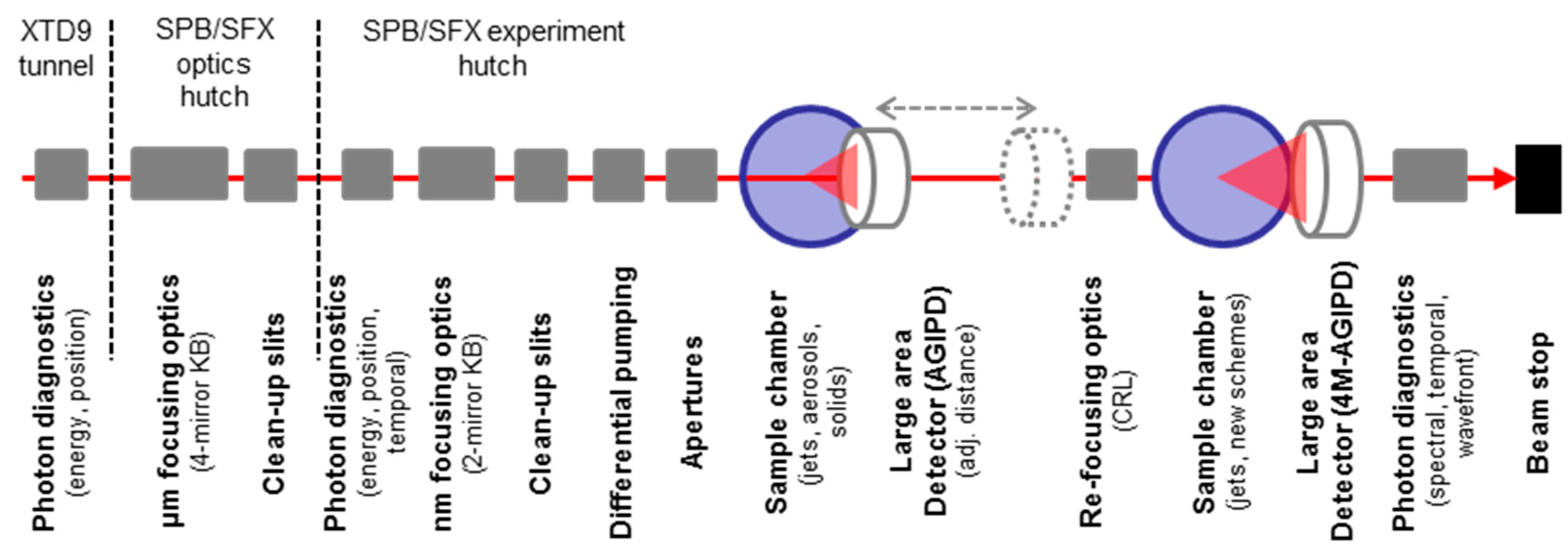
5. The SPB/SFX Instrument

5.1. Scientific Scope and X-ray Techniques

The Single Particles, Biomolecules and Serial Crystallography (SPB/SFX) scientific instrument’s [61] primary goal is to enable three-dimensional imaging, or three-dimensional structure determination, of micrometer-scale and smaller objects. A particular focus is placed on biological objects—including viruses, biomolecules, and protein crystals—though the instrument will also be capable of investigating non-biological samples using similar techniques. This structure determination is not limited to static structures—three-dimensional time-resolved structures are within scope too. One of the main driving factors for such studies is to ultimately enable rational drug design through understanding the structure, and hence the function, of arbitrary biomolecules. Studies in structural biology with X-rays have a long history and have exploited ever-brighter X-ray sources as they have been developed [62].
X-ray FELs, as the most recent phase in X-ray source development, offer yet additional benefits to structural biology with X-rays. In particular, they offer the possibility to investigate radiation damage sensitive samples (such as proteins with important metal centers), samples that scatter only weakly (small crystals or non-crystalline specimens), time-resolved processes that are irreversible, as well as other cases that inherently require many incident X-ray photons in a single pulse [63,64]. Unprecedented possibilities are opening to observe weakly scattering samples, such as small crystals of proteins or perhaps even non-crystalline bio-samples such as viruses, which are largely unable to be seen at synchrotron or lab based X-ray sources. Nevertheless, techniques that are relatively simple at conventional sources, such as tomography, are not viable at an X-ray FEL where samples are typically destroyed by the act of illumination in a single projection. This reality means that many frames of data from different projections of a crystal or (reproducible) particle must be combined to form a complete three-dimensional diffraction volume that can be interpreted later as structure [65,66]. These methods require as many as tens of thousands or hundreds of thousands of “good” hits for a single structure [67,68]—and many more should one wish to look at a series of structures resolved in time for example.

5.2. Requirements

These experiments require X-ray instrumentation in a traditional forward scattering geometry to collect diffraction at angles up to those commensurate with atomic resolution. Crystallography requires photon energies up to about 16 keV—beyond the Selenium edge—to aid in anomalous diffraction measurements for structure determination. On the low energy side, single particle imaging, which deals with typically very low diffraction signals, requires as low a photon energy that permits the desired resolution for the system under study. Furthermore, mitigation of radiation damage requires optimization of the beam power, that is, to carefully trade highest pulse energy versus shortest pulse duration.
X-ray FEL serial crystallography and imaging experiments are primarily performed in a mode that is destructive to the sample. The goal is to illuminate the specimen with as many X-ray photons per pulse as possible, to maximize the scattered signal from each particle. To do so, one must have an optical system that is highly transmissive, as well as focusing to a spot size that is comparable to the size of the sample(s) under investigation. The “small” crystals used in serial crystallography at XFELs tend to be around 1 µm diameter in size, with some variation larger or smaller. Relevant biological single particles range from biomolecules some tens of nanometers across to large viruses up to 500 nm in diameter. To accommodate this wide range of sample sizes, the SPB/SFX instrument plans to deliver two different focal spots—a 1 µm-scale focus and a 100 nm-scale focus. Coherent diffraction imaging of individual particles further requires precise knowledge of the wavefront of the incident X-ray pulse leading to stringent requirements on the selection of the X-ray optical components and their performance.
Of particular importance for the experiments to be performed at SPB/SFX will be the performance of the large area detectors. The two primary requirements are a very high dynamic range and single photon sensitivity. An ideal 2D detector for serial crystallography should have a high dynamic range much higher than the four [31] or five [32] orders of magnitude presently achievable, as the intensities of individual Bragg peaks can vary enormously and these intensities must be determined very accurately for successful phasing and structure determination (though nevertheless a detector with 104 or smaller dynamic range can be successfully used). Single photon sensitivity is important for detecting weaker scattering, such as from single non-crystalline particles or weak Bragg peaks. The detectors should be compatible with detection at the 4.5 MHz intra-train repetition rate to ensure collection of as much images as possible within a meaningful time frame during which particles can be injected. This requirement leads to the further need for stringent data reduction techniques to avoid a data deluge. Finally the detector(s)’ mechanical design must be compatible with the instrument. This means a pixel size that is not too large (≤200 µm), a number of pixels commensurate with the number of resolution elements desired in any given structure (i.e., ≥1 MPixel for ~200 linear resolution elements) and an operation that is ideally compatible with the sample environment (for the upstream interaction region at SPB/SFX this means in vacuum operation). The detector is required to operate in vacuum and be placed as close as 129 mm from the upstream interaction region, resulting in a better than 2 Å geometrical resolution limit for 9 keV photon energy. It can also be placed downstream as far as 6 m from the interaction region, allowing for appropriate sampling of diffraction data from samples as large as almost 1 µm at the lowest energies.

5.3. SPB/SFX Instrumentation and Capabilities

The SPB/SFX instrument is a 3 to 16 keV, forward scattering instrument [61] with a 1 µm-scale and a 100 nm-scale focus in the upstream interaction region [69,70], and optics to refocus the upstream focal point to a second interaction region further downstream (about 12 m) in the experiment hutch. This refocused beam allows for a second, in series, experiment to be performed simultaneously with a measurement in the upstream interaction region (see Figure 4). The Serial Femtosecond Crystallography (SFX) User Consortium provides the vast majority of the instrumentation for the downstream interaction region including, but not limited to, a 4 Mpixel detector (AGIPD) and an alternative detector (Jungfrau), the refocusing CRLs, sample delivery technologies (largely liquid jet delivery in various forms and fixed target systems) as well as various diagnostics and sundry apparatus. The 1 µm-scale and 100 nm-scale focal spots for the upstream interaction region of the SPB/SFX instrument are to be produced by mirror optics due to their high transmission and potential for making very neat and well confined focal spots. The mirrors are all designed with 950 mm clear aperture, with working angles of 4 mrad and 3.5 mrad, respectively.
The 100 nm-scale design is a traditional Kirkpatrick–Baez (KB) design. The 1 µm-scale mirrors are four-bounce—with a plan horizontal mirror followed by a focusing ellipse in the horizontal and then a focusing vertical mirror with a plane vertical mirror. This four bounce design mitigates vibrational issues and a large displacement from the direct beam over the long (~24 m) mirror to interaction region distance. For early user operation in 2017, the mirrors will not yet be installed. Instead, Beryllium compound refractive lenses (CRLs) will be used to produce an approximately 2.5 µm spot in the interaction region. After mirror installation, the CRL unit will be moved to the refocusing position and new lenses installed to refocus the upstream spot to ~3–5 µm in the second interaction region downstream.
In addition to focusing elements, a variety of beam conditioning apparatus (slits, apertures and attenuator) will be installed to aperture the beam upstream of the optics (the so-called power slits), clean up tails and streaks from the optics immediately downstream of them (the so-called cleanup slits) and apertures near the focal plane that further clean up the beam (termed apertures and will likely be sacrificial). This beam conditioning is essential for single particle imaging where a very neat, clean and well-understood beam is necessary for the successful observation and interpretation of the weak diffraction data collected.
The primary 2D detector at SPB/SFX is a 1 Mpixel AGIPD detector [31]. It will be mounted in a vacuum chamber directly attached to the upstream sample chamber. Using a longitudinal translation, it can be placed as close as 129 mm from the interaction region, resulting in a better than 0.2 nm geometrical resolution limit for 9 keV photon energy. It can also be placed downstream as far as 6 m from the interaction region, allowing for appropriate sampling of diffraction data from samples as large as almost 1 µm at the lowest energies. The detector mechanics consists of four panels mounted on x-y-translations to adjust the central hole for letting the X-ray beam pass.
The destructive nature of these experiments and the high repetition rate of the European XFEL necessitate rapid delivery (and replenishment) of sample at the interaction region. Furthermore, for biological systems the samples must be appropriately hydrated and handled to ensure an intact and representative sample is brought to the XFEL beam. Three primary sample delivery mechanisms exist for the delivery and replenishment of samples: liquid jet injectors, aerosol injectors and fixed target stages, all of which will be deployed at the SPB/SFX instrument.

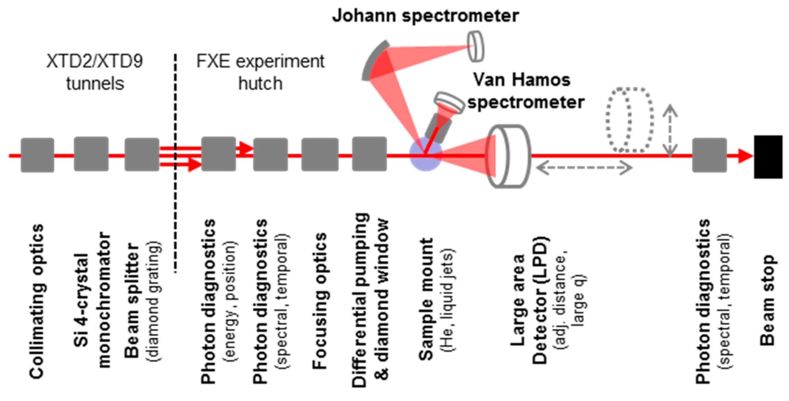
6. The FXE Instrument

6.1. Scientific Scope and X-ray Techniques

The Femtosecond X-ray Experiment (FXE) scientific instrument has a primary scientific focus in the field of photo-induced chemical dynamics in liquid environments [71]. The interplay between nuclear, electronic, and spin degrees of freedom during the course of an ongoing reaction will be monitored using a suite of X-ray techniques, thereby offering new observables in the femtosecond time domain to deliver this information. The FXE instrument will permit structural studies on the 25 fs time scale and below, with ultrafast X-ray Absorption Near Edge Structures (XANES), Extended X-ray Absorption Fine Structure (EXAFS), Resonant Inelastic X-ray Scattering (RIXS), non-resonant X-ray Emission Spectroscopy (XES), and Wide Angle X-ray Scattering (WAXS) from liquids being key techniques to unravel new details about the very first steps in these reacting systems. One fundamental goal is to eventually record a complete molecular movie, observing not only the structural rearrangements occurring in the system but also of the underlying electronic structure changes. Together with ultrafast optical spectroscopy techniques it will become possible to understand the ensuing photo-physical behavior.
One particular interesting area of research concerns catalytic activity and solar energy conversion schemes, which occur in several transition metal compounds. Such compounds are key ingredients in certain proteins, and are often at the very beginning of light-driven biological functions [72]. They are also studied in chemistry due to their rich magnetic switching behavior [73], their charge-transfer properties in light-harvesting applications [74], or for their ability to form highly reactive intermediate species, which enhance further reaction steps, e.g., towards more efficient catalytic behavior [75]. These compounds are believed to exhibit correlated electron dynamics in a regime in which the Born-Oppenheimer rule is not valid. The direct observation of elementary steps towards, e.g., spin transition dynamics has so far been impossible which is expected to change due to the possibility of studying new observables in X-ray FEL experiments [76,77].

6.2. Requirements

The different X-ray techniques offered at FXE have quite different requirements to the FEL source. XES requires merely the photon energy to be well above the absorption edge of the selected element. The same condition applies to WAXS while the bandwidth of SASE radiation is perfectly suited for diffuse scattering measurements [77]. Therefore both techniques can be applied simultaneously. More demanding X-ray beam properties exist for XANES, EXAFS or RIXS techniques, requiring smaller bandwidth of the incident beam (typical ∆E/E ~ 10−4), and scanning the photon energy over a certain range at the selected absorption edge. This scanning requires tuning of the undulator gap together with a primary monochromator.
All X-ray techniques need to be used in concert with an incident laser beam, whose femtosecond pulses are synchronized to the X-ray source, and with sufficient intensity to trigger the desired reactions. The experiments also require appropriate handling of the probed samples. For (bio)chemical systems in liquid solutions, the sample should be removed after each pump-probe event, to permit the next measurement to be recorded on a fresh sample, which has not been exposed to neither the optical laser nor X-ray beams before. To preserve the femtosecond time resolution, the time spread through the sample via the group velocity mismatch between optical and X-ray pulses needs to be minimized. In general, this requires a jet thickness below 10–20 um.

6.3. FXE Instrumentation and Capabilities

X-ray FEL radiation from the SASE1 FEL is collimated by means of Be compound refractive lenses (CRL) 900 m upstream from the experiment hall in XTD2 in order to maintain a beam size in the 1–2 mm (FWHM) diameter range (for all X-ray energies in the 5–20 keV range), when the beam enters the primary four-crystal monochromator, diamond beam splitter grating and eventually the FXE experiment hutch (compare Figure 5).
The primary Si four-crystal monochromator (ΔE/E = 10−5–10−4) maintains the same beam axis for the X-ray beam onto the sample as the pink beam (thus without monochromator), this way we ensure that the laser beam always strikes the X-ray illuminated volume, and that the X-rays always take the same path through the entire optics branch including the long stretch downstream to the beam stop. This arrangement eliminates the need to geometrically adjust the beam(s) for varying conditions, as demanded by the specific experiment. Only the timing changes considerably between pink and monochromatic pulses entering the sample, especially the monochromatic beam has different arrival times (with respect to the exciting optical laser pulses), which can be tabulated for each energy.
At the end of the tunnel section a diamond grating generates side maxima (diffraction orders) of the main X-ray beam, which are used for X-ray beam diagnostics inside the experiment hutch (similar to what has been described in Ref. [78]). The side beams can be used to measure the incident spectrum of the X-ray beam via a curved crystal spectrometer, and the actual arrival time of the X-ray pulse with respect to the optical laser pulse. Together with beam shaping slits and an intensity position monitor the conditions of the beam entering the sample are thus well characterized.
With a second stack of Be CRL lenses the X-ray spot size on sample can be freely tailored to values in the 2–200 um range (FWHM). The X-rays enter the sample area via a diamond window separating the ultrahigh vacuum optics branch from the sample environment under ambient conditions (He atmosphere at room temperature). A liquid flat sheet jet with adjustable thickness in the 2–200 um range provides a defined surface for optical excitation and X-ray probing. Two secondary spectrometers are available for XES experiments, and each can also be rotated around the sample from forward to nearly backward scattering angles: a Johann spectrometer with up to 5 spherically bent crystals collects single emission wavelengths with a resolution of ΔE/E = 10−4. This spectrometer has a large solid angle and spectra are obtained by scanning both the crystal rotation with the collecting detector on a Rowland circle. Alternatively, a 16 element von Hamos type spectrometer collects the entire XES spectra at a resolution of ΔE/E ~ 10−3 without moving elements, thus enabling single-pulse experiments.
The forward WAXS scattering pattern is collected using the LPD detector [32] having moveable quadrants for a central hole for the X-ray beam with adjustable size in the 1–10 mm range. A post-diagnostics bench can then record the beam properties (spectrum, intensity, and timing) of the transmitted beam, before it finally strikes the copper beam stop.

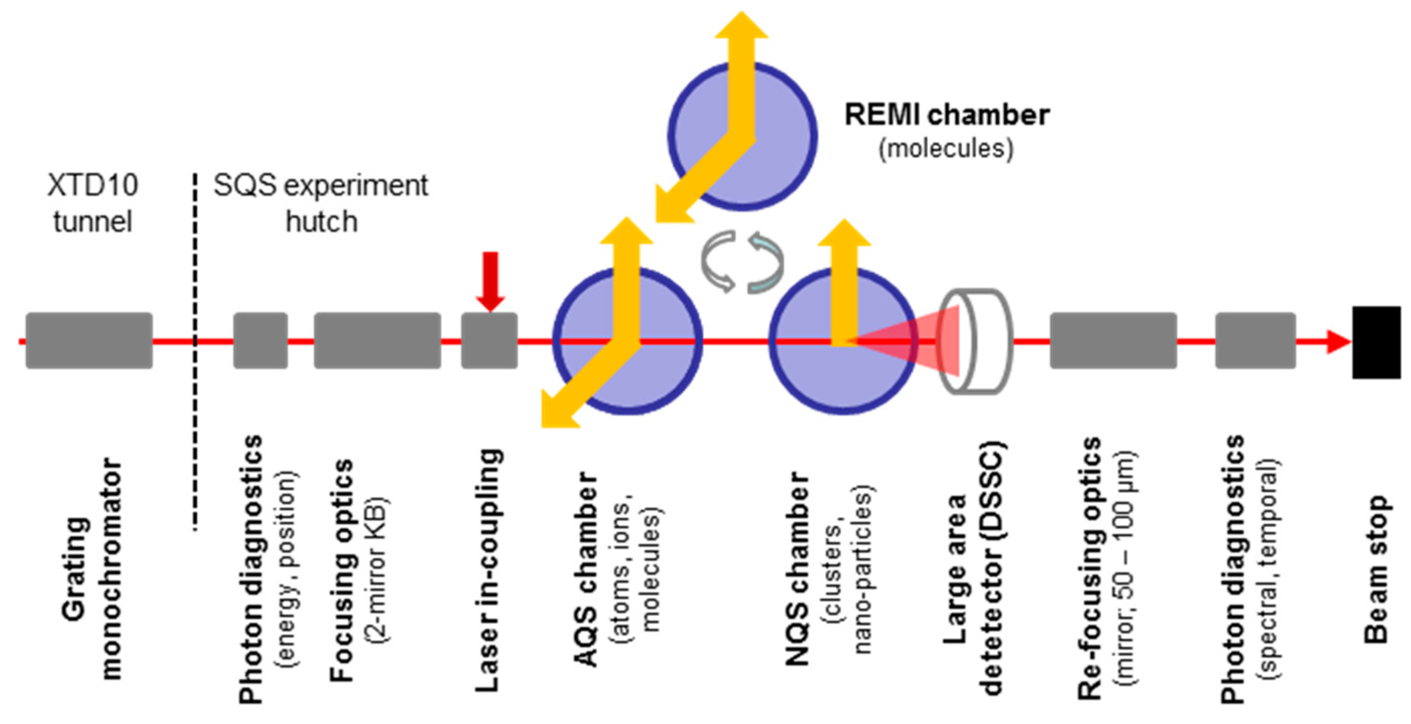
7. The SQS Instrument

7.1. Scientific Scope and X-ray Techniques

The SQS (Small Quantum Systems) scientific instrument is dedicated to investigations of fundamental processes of light-matter interaction in the soft X-ray wavelength regime. In particular, studies of non-linear phenomena, such as multiple ionization and multi-photon processes, time-resolved experiments following dynamical processes on the femtosecond timescale, and investigations using coherent scattering techniques are targeted [79]. Principal research targets are isolated species in the gas phase, such as atoms, molecules, ions, clusters, nanoparticles and large bio-molecules. The use of soft X-ray photons enables controlled excitations of specific electronic subshells in atomic and site- or element specific excitation in molecular targets. One of the main goals of the SQS instrument is the complete characterization of the ionization and fragmentation process, at least for smaller systems, by analyzing all products created in the interaction of the target with the FEL pulses.
Experiments at SQS typically use X-ray pulses of highest intensity to drive the probed system to highly excited states or initiate non-linear X-ray processes. The additional use of synchronized optical laser pulses will be applied to controlled manipulations of the electronic states and nuclear movement. Probing of the X-ray FEL interaction with the sample system will be performed either by direct coherent X-ray scattering to obtain structural information or by spectroscopic techniques. A focus is put on a variety of particle spectroscopy techniques, such as energy- and angle-resolved electron and ion spectroscopy allowing the determination of kinetic energies and momenta of the charged particles, and additional options for XUV and soft X-ray spectroscopy. In particular, the very open and flexible arrangement of the spectrometers will enable the application of various coincidence techniques, such as electron–electron, electron–ion and photon–electron/ion coincidences, which all require and therefore take full advantage of the high repetition rate available at the European XFEL.

7.2. Requirements

Located at the SASE3 FEL the photon energy of the radiation will range from about 250 eV up to 3000 eV, i.e., covering the energy range of ionization thresholds for numerous relevant atoms such as the K-edges of carbon, nitrogen, oxygen as well as of phosphor and sulfur, the L-edges of the 3d transition and rare earth metals and K- and L-edges of various ions. Pulse durations as short as 2 fs, available in the 0.02 nC low-charge mode, enable in combination with the synchronized optical laser time-resolved studies in the few-femtosecond time domain. Furthermore, pulse energies of up to 10 mJ are produced at 1 nC high-charge mode. This high pulse energy corresponds to 2 × 10¹⁴ photons per pulse and is the main requirement for the study of non-linear processes, since intensities of more than 1018 W/cm2 can be reached by focusing, e.g., the 10 mJ/100 fs FEL beam to a diameter of about 1 µm.
Ultra-high vacuum conditions in the experimental area are required for coincidence techniques in order to minimize signals caused by ionization of residual gas. For this reason most of the experiments will operate at background pressures of about 10−10 mbar or less and supersonic molecular jets and specially designed quantum-state-, size-, and isomer-selected beams of polar molecules and clusters (COMO for “Controlled Molecules”) will be used for sample delivery. These vacuum conditions will be reduced for experiments on larger targets requiring the use of the large DSSC imaging detector and of dedicated cluster or nanoparticle beam devices.

7.3. SQS Instrumentation and Capabilities

The optical layout of the beam transport system enables experiments using the direct beam from the variable gap SASE3 undulator or the reduced bandwidth radiation (∆E/E ≤ 10−4) from the soft X-ray monochromator. A Kirkpatrick–Baez adaptive mirror system assures a tight focusing of the beam down to spot sizes as small as about 1 micron (see Figure 6). The bendable high-polished mirrors allow adjustments of the focal spot size and displacement of the focus to three different interaction regions separated by 39 and 200 cm, respectively. The FEL radiation properties, such as pulse energy, pulse duration, arrival time, spectral distribution and focal spot size, are monitored with the help of several diagnostic devices installed downstream and upstream of the interaction regions inside the dedicated and enclosed experiment area.
The general concept of the instrument is based on a two-chamber system thus separating applications on “Atomic-like Quantum Systems” (AQS), such as free atoms, atomic ions, and small molecules, and on “Nano-size Quantum Systems” (NQS), such as clusters, nanoparticles and large biomolecules, all typically larger objects [79]. The AQS chamber will be equipped with a set of spectrometers enabling the analysis of electrons, ions and photons with high-energy resolution and the determination of the angular distribution of the particles. Six electron time-of-flight (TOF) analyzers can be used for angle-resolved high kinetic energy resolution experiments at distinct angles in the dipole and in the non-dipole planes. A velocity-map-imaging (VMI) spectrometer provides the full information about the angular distribution of the emitted electrons and ions, and is designed for electrons up to about 1000 eV kinetic energy. The single pulse analysis of very dilute samples or of processes characterized by extremely low cross sections is possible by means of a magnetic bottle electron spectrometer, which collects electrons over the full solid angle. Finally, a specially designed 1D-imaging XUV spectrometer is dedicated to the analysis of fluorescence emission at high spectral resolution. The use of Wolter optics and a 2D-imaging detector is enabling a spatial resolution of about 10 μm along the beam propagation direction and thereby a temporal resolution of about 30 fs in crossed beam experiments.
The NQS chamber will have as particular feature the option to use the DSSC detector [33] in forward diffraction geometry. Due to the high scattering cross sections in the soft X-ray regime, single pulse imaging of larger molecules and particles becomes possible and will be applied to structural analysis at reduced spatial resolution. The DSSC detector is also used in combination with various particle spectrometers (TOF, VMI) to characterize size and shape of clusters and nanoparticles in parallel to the determination of kinetic energies, fragmentation patterns and emission angles of ions and electrons produced in the interaction volume.
In addition, a third, specially designed ultra-high vacuum chamber will host a reaction microscope (SQS-REMI) for the complete characterization of molecular fragmentation processes by the application of electron–ion coincidence techniques [80], taking full advantage of the high repetition rate (until 27,000 pulses per second) available at the European XFEL. Using large area position sensitive delay-line detectors and a well-defined arrangement of magnetic and electric fields to extract and guide the electrons and ions, the kinetic energies of all fragments as well as their relative emission angles can be determined in a single molecule ionization event.
Specially designed in- and out-coupling units for the optical laser are available to provide the optical radiation to all three interaction points in collinear geometry. In general, great emphasis is placed on a flexible design and arrangement of the experimental chambers and the various spectrometers, which will enable users to make optimal use of all the specific characteristics of the European XFEL, in particular of its uniquely high repetition rate. Furthermore, several extensions of the FEL beam parameters (e.g., variable polarization or two-color operation), beam delivery capabilities (beam splitter and delay device) and instrument layout are already decided or under investigation.

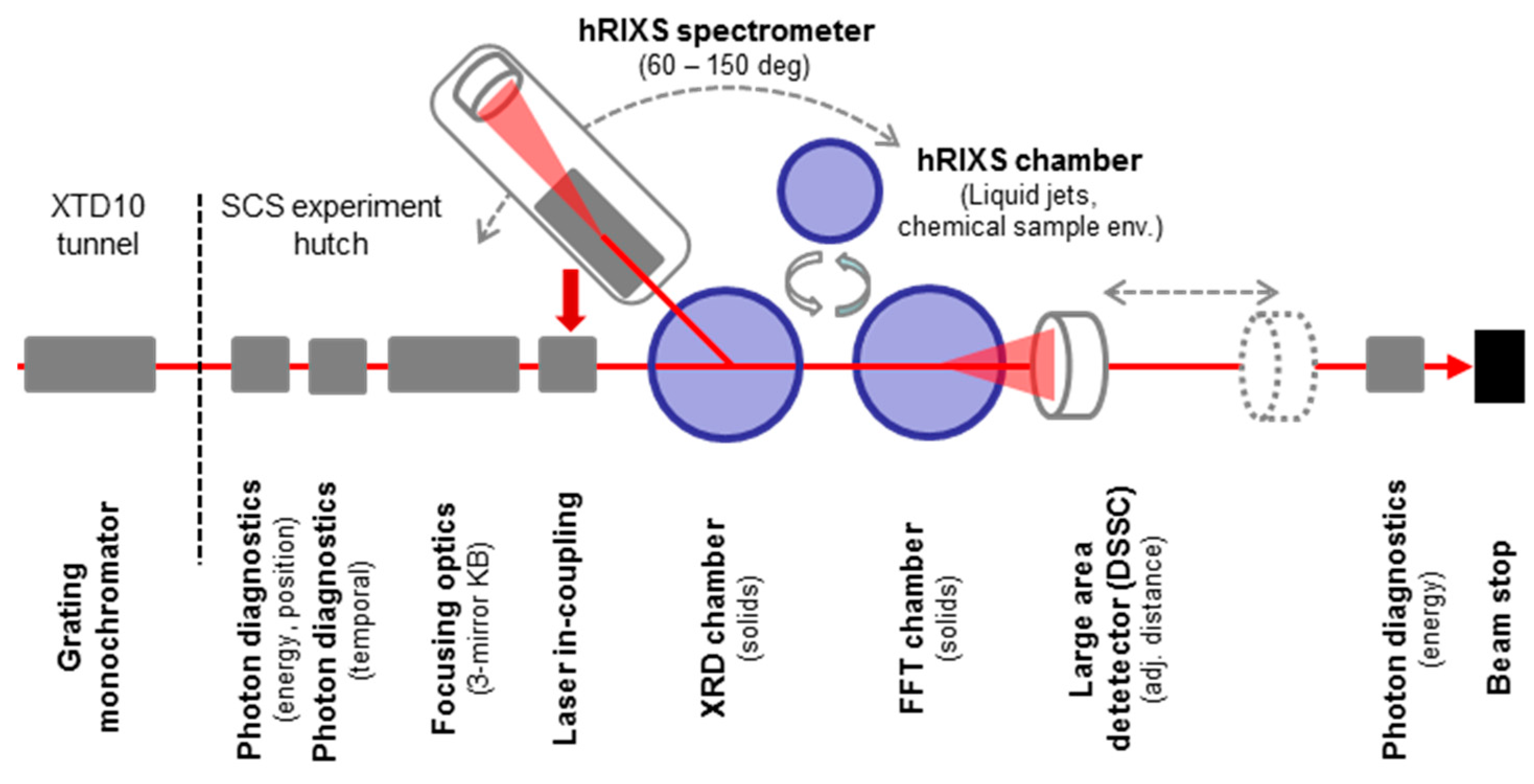
8. The SCS Instrument

8.1. Scientific Scope and X-ray Techniques

The Spectroscopy and Coherent Scattering (SCS) scientific instrument is located at the SASE3 FEL source and aims at time-resolved experiments to unravel the electronic, spin and structural properties of materials in their fundamental space-time dimensions. Scientific objectives include, but are not limited to the understanding and control of complex materials [81,82,83], the investigation of ultrafast magnetization processes on the nanoscale [84,85], the real-time observation of chemical reactions at surfaces and in liquids [86,87], and the exploration of nonlinear X-ray spectroscopic techniques that are cornerstones at optical wavelengths [17,88].
The SCS instrument operates in the soft to tender X-ray regime (250 eV–3000 eV) covering a wide range of core level resonances: K-edges of most 2p and 3p elements (starting from carbon), L2,3-edges of 3d and 4d elements (transition metals) and M4,5 edges of 4f elements (lanthanides). Time-resolved resonant spectroscopy offers element-, site-, orbital-, and spin-selective probing of complex material dynamics that is either directly related to or indirectly coupled to the valence electrons. Physical properties such as oxidation state, magnetism, local symmetries and ordering as well as elementary excitations can be investigated using X-ray Absorption Spectroscopy (XAS) [86,89], X-ray Resonant Diffraction (XRD) [81,82,83] and Resonant Inelastic X-ray Scattering (RIXS) [87]. A particular aim of the SCS instrument is to combine these powerful spectroscopic techniques with X-ray diffraction and microscopy methods, which provide nanometer spatial- and femtosecond time resolutions. Such experiments open up a route to follow the dynamics in complex systems on their relevant length and time scales. The SCS instrument further implements Coherent Diffraction Imaging (CDI) techniques, i.e., X-ray holography [90,91]. A time series of reconstructed CDI images can elucidate excited state dynamics in real space.

8.2. Requirements

The monochromatic-beam operations described in Ref. [92] are key to the success of the SCS instrument. The SASE3 soft X-ray monochromator is equipped with two gratings and a flat mirror that allows for monochromatic beam operation at high (ΔE/E = 2.5 × 10⁻⁵) and medium energy resolutions (ΔE/E = 1 × 10⁻⁴) as well as non-monochromatized beam operations without changing the beam transport to the sample. A tunable grating illumination concept is therefore implemented to provide a minimum spectral bandwidth-time duration product [92]. In this way, RIXS experiments with high energy-resolution and lower time resolution as well as ultrafast dynamics studies at reduced energy resolutions (e.g., femtosecond surface chemistry and magnetism) can be performed at the same experiment station of SCS. New developments for the FEL source, such as full polarization control and undulator gap scanning techniques, will be implemented at SCS. These are nowadays standard capabilities at synchrotron facilities for X-ray spectroscopy investigations.
The majority of the experiments will require X-rays to impinge on fixed solid targets that cannot easily be replenished between X-ray pulses, in contrast to liquid jet or particle injection schemes. This sets particular constraints on the optical and X-ray pulse energies in pump-probe experiments when sample damage or degradation by the radiation and heating have to be mitigated to a level that sufficient data acquisition is possible between the sample exchanges. Heat dissipation schemes have to be developed in order to reach the ultimate 4.5 MHz burst mode operation, where the sample relaxation time and the heat dissipation in the probed area must be shorter than 220 ns.
While time-resolved spectroscopy experiments on fixed targets require high average photon flux, CDI and nonlinear X-ray-matter–interaction experiments need the highest pulse energies. In single shot imaging experiments the number of incoming photons determines the attainable resolution and therefore, depending on the damage threshold, requires the experiment to be carried out in a “diffraction before destruction” mode [93]. In this case, a new sample has to be repositioned in the beam between the X-ray bursts at 10 Hz repetition rate and a pulse selection mode is necessary.

8.3. SCS Instrumentation and Capabilities

One of the major goals of the technical design was to implement a diverse platform for spectroscopy and coherent scattering techniques that is realized in a modular instrumentation of experiment stations and detectors. The mirror benders of the SCS Kirckpatrick–Baez refocusing optics deliver the beam to two X-ray interaction regions separated by 2 m (see Figure 7). This allows not only a small beam focus of 1–2 µm for CDI experiments but also a variable beam diameter of up to 500 µm. In this way, time-resolved spectroscopic studies can be carried out making the best use of the high-average photon flux without further beam attenuation for avoiding sample damage.
The SCS instrument comprises two distinct experimental setups, the Forward-scattering Fixed-Target (FFT) chamber and the XRD chamber. Both chambers have the same mechanics on their base that locks to three fixation points on the floor, one set per interaction region. This allows for faster exchange of experiment stations and reproducible repositioning of the chambers.
The FFT chamber is optimized for forward-scattering geometries such as XAS in transmission, small-angle X-ray scattering (SAXS) and CDI experiments. Besides optical and THz beam delivery the sample environment encompasses static magnetic fields up to 0.5 T and a fast sample scanner that fits 50 × 50 mm2 sample arrays. The diffraction signal from the samples is collected downstream on the primary area detector, DSSC. The detector is mounted on a girder with a 5 m long translation stage. The closest sample-detector distance is 350 mm, corresponding to spatial frequencies near the wavelength limit of a few nm at soft X-ray energies. Objects of up to 3–5 µm in diameter can be reconstructed using CDI at a sample-detector distance of 5 m and photon energies below 1.5 keV. The missing low-q data passes through a hole in the center of the detector and is recorded downstream as an integrated sample transmission signal. Since the monochromatic beam intensity jitter is large, data collected from low intensity pulses can be vetoed using the DSSC detector [33]. In this way, the signal to noise level of the data can be improved and data acquisition time is optimized.
The XRD chamber enables a range of time-resolved spectroscopy and scattering methods for which a variable scattering angle is needed. The most relevant techniques are time-resolved XRD and RIXS as well as nonlinear X-ray studies (stimulated emission and scattering). The XRD setup is equipped with a diffractometer where a diode array can be rotated by nearly ±180° in the horizontal scattering plane. The sample motion system provides six degrees of freedom and enables temperature-dependent studies between room temperature and cryogenic temperatures (liquid He cryostat). A detector flange with 90° continuous rotation can interface with large detectors and spectrometers. The Heisenberg-RIXS (hRIXS) User Consortium is contributing a high-resolution spectrometer (ΔE/E = 0.25 − 1 × 10⁻⁴) that facilitates state-of-the-art RIXS experiments with unprecedented time-resolution at the SCS instrument. The 5 m long hRIXS spectrometer can rotate around the sample position, hovering 50 µm above a high-planarity floor (250 µm peak-to-valley over 37 m2) on air pads.
Both experiment chambers are designed for solid targets and operate in the 10−9 mbar pressure regime depending on the detector vacuum. The chambers are equipped with a sample transfer system for exchanging samples under vacuum conditions. Optical laser delivery can be either collinear to the X-ray beam or arranged in off-axis geometry. THz generation and focusing takes place close to the interaction region and temporal diagnostics at the sample interaction point is realized. The hRIXS User Consortium will contribute an additional experiment station that provides a chemical sample environment including liquid jet systems of different geometries and couples to the hRIXS spectrometer.

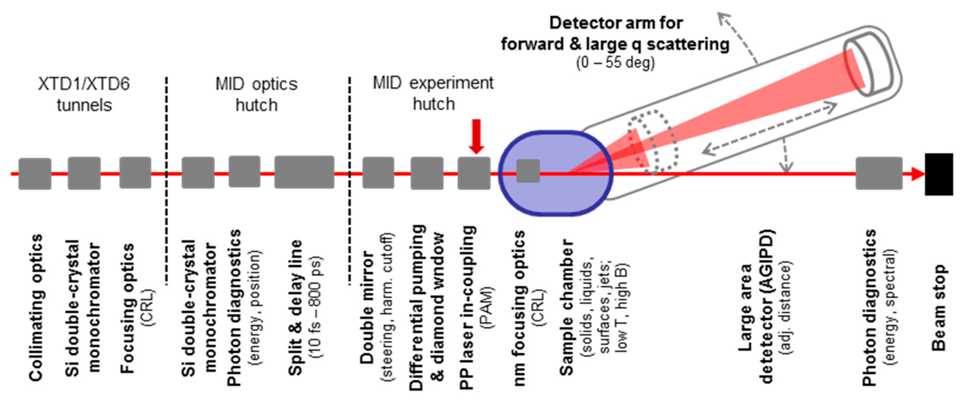
9. The MID Instrument

9.1. Scientific Scope and X-ray Techniques

The Materials Imaging and Dynamics (MID) instrument of the European XFEL facility, located at the SASE2 beamline, will provide unique capabilities in ultrafast imaging and dynamics of materials, with particular focus on the application of coherent X-ray scattering and diffraction techniques. Coherent diffractive imaging (CDI) [94,95] and X-ray photon correlation spectroscopy (XPCS) [18,96,97,98] experiments are at the heart of the activities planned. In addition, high resolution time-resolved scattering [99,100], nano-beam scattering/imaging [101,102] and novel correlation techniques [103] are foreseen at MID taking advantage of the unique time structure and high peak intensity of the European XFEL beam. The instrument can operate in small-angle (SAXS) and wide-angle (WAXS) X-ray scattering configurations with a movable large area detector. A large field-of-view configuration where the detector covers a maximum of reciprocal space is also possible. The instrument is optimized for windowless operation over a wide range of photon energies, 5–25 keV, and possibly higher in the future depending on the development of novel lasing schemes using the SASE2 FEL.

9.2. Requirements

The MID design has been guided by several goals. Firstly, the aim is to preserve the high average and peak brilliance provided by the source and make use of as many photons as possible in the experiments. At the same time, optimum conditions for beam tailoring must be ensured concerning focusing, energy selection, and spectral purity in a setup providing high beam stability (position, intensity) and fast and efficient data collection with the highest possible resolution. A versatile setup was required to enable the breadth of experiments that will take place at MID. The experimental setup is hence windowless (optional), multi-purpose and also contains beam diagnostics tools, both for the X-ray beam and the optical pump laser. MID strives to provide the best possible conditions for materials science experiments using hard X-ray FEL radiation, for instance in the studies of nanostructured materials, phase transitions and metastable states, liquid dynamics, and low-temperature physics and magnetism.

9.3. MID Instrumentation and Capabilities

The MID instrument is mainly installed in two safety hutches, an optics hutch (OH) and an experiment hutch (EH), but several essential components are also placed inside the SASE2 photon beam transport tunnel (see Figure 8). The OH contains a Si(220) monochromator to reduce the bandwidth of the SASE radiation to ∆E/E ~ 6.1 × 10⁻⁵ if required. An additional Si(111) mono (∆E/E ~ 1.4 × 10⁻⁴) installed in the SASE2 tunnel can be used to pre-monochromatize or separately. Alternatively, the SASE beam can be applied directly (∆E/E ~ 1 × 10⁻³) or in self-seeded mode [104,105] (∆E/E ~ 1 × 10⁻⁵) once self-seeding becomes available at SASE2. Together with undulator tapering this will allow achieving more than 1012 ph/pulse and a record high spectral peak brightness of more than 1014 ph/s/meV at 9 keV [106]. The OH contains beam attenuators and slits for further beam tailoring as well as an imager system to provide in-situ visualization of the beam size, shape, and intensity. A split-and-delay line (SDL) [107,108] will also be installed in the OH and will give the possibility of modifying the time-structure of the beam. Normally, the European XFEL delivers ultrashort (~1–100 fs) pulses of photons every 220 ns (4.5 MHz), but with the SDL under construction for MID it is possible to reduce this spacing to any value from ~10 fs to 800 ps [109]. This enables particular experiments requiring such an X-ray pulse pattern, e.g., speckle visibility techniques [110,111] for ultrafast dynamics or X-ray pump X-ray probe, possibly in combination with an optical fs laser pump [112]. The latter gives the additional option of performing X-ray probe–Optical pump–X-ray probe measurements where the two pulses from the SDL are not only delayed in time but also are hitting the sample at different angles of incidence. This provides a unique possibility to distinguish the two X-ray diffraction patterns hitting the detector and a spatial encoding of ultrafast dynamics can hence be obtained to yield a time-resolution much better than the 4.5 MHz detector speed [112].
In the EH, the beam first passes through a double mirror system (if inserted) that allows reflecting the X-ray beam downwards for grazing incidence liquid surface scattering. Another mirror reflecting upwards provides the aforementioned option of different incidence angles for the two split beams from the SDL. Downstream of the mirror system the ultra-high vacuum (~10−9 mbar) section of the instrument terminates and it is necessary to operate at a lower vacuum level or even at ambient conditions due to the presence of outgassing substances, sample environments, and electronics. This transition is ensured either by insertion of a beam transparent diamond window, or by use of the differential pumping section positioned immediately downstream of the mirror. A large multi-purpose sample chamber (MPC) hosts local optics for nano-focusing, a hexapod sample manipulation stage, as well as different sample environments, e.g., providing low-temperatures via He cryo-cooling, pulsed high magnetic fields, fast sample scanning, sample injection by liquid jets, aerosol injection, etc. To ensure a maximum of stability the stages carrying the nano-focusing setup and the sample hexapod are decoupled from the vacuum pipes and chamber walls and connected directly, via vacuum feedthroughs, to a several ton heavy granite block below the MPC. A focal spot down to 50 × 50 nm2 or smaller is enabled by the nano-focusing system [112]. Assuming full transmission of the FEL pulses this could enable peak intensities of beyond 1021 W/cm2 [39,113,114] allowing to explore non-linear X-ray interactions with matter, e.g., two- or multi-photon processes in scattering and absorption [115,116,117]. The PP laser beam is delivered to EH via a transfer pipe to a laser table next to the MPC allowing additional tailoring of the beam before it is directed towards the sample position. Temporal and spatial overlaps of the optical laser beam and the X-rays can be controlled through imaging and timing diagnostics [49] and tuned by adjusting optical components in the laser beam path located in the ILH.
The radiation scattered from the sample is measured using the AGIPD detector. In SAXS configuration the distance from sample to detector can be varied from ~200 to 8000 mm. This provides an angular detection resolution between 1 mrad and 25 µrad and a field-of-view between 1 rad and 25 mrad. With the direct beam in the center of the detector at 10 keV, it translates into a q-resolution and q-range of 5.0 × 10⁻³ and 2.3 Å−1 for 200 mm, and 1.3 × 10⁻⁴ and 6.3 × 10⁻² Å−1 for 8000 mm, respectively. Special configurations with even shorter sample-detector distance and exploitation of the full energy range of the instrument (5–25 keV) allow tuning these values. In the SAXS case, a hole in the center of the detector (adjustable by movable quadrants) permits unhindered passage of the direct beam, i.e., without destroying the sensor. The exit port of AGIPD is connected to a diagnostics end-station where intensity, size and spectrum of the transmitted beam can be quantified with high resolution. In particular, a semi-transparent bent diamond spectral analyzer has been developed allowing to quantify the SASE spectrum down to a resolution of ~0.1 eV [118]. This spectrometer will operate in parallel with AGIPD and the spectral information together with scattering data enable a better data analysis as well as easy tuning of the self-seeded mode. A similar transparent diamond spectrometer can be inserted upstream of the MPC to measure the spectrum before interaction with the sample [118]. In this manner absorption spectroscopy [119] can be combined with, e.g., pump-probe and coherent scattering techniques providing unique new possibilities of investigating interactions of ultra-bright fs X-ray pulses with matter.
The MID instrument also features the option of measuring in a horizontal WAXS geometry (scattering angle up to ~55° with the sample-detector distance varying between 2000 and 8000 mm. This will enable high resolution detection at large q (beyond 10 Å−1) investigating (coherent) diffraction originating from, e.g., structural, charge, or magnetic ordering in combination with the pulsed magnetic field or the fs pump laser to access ultrafast dynamics processes.

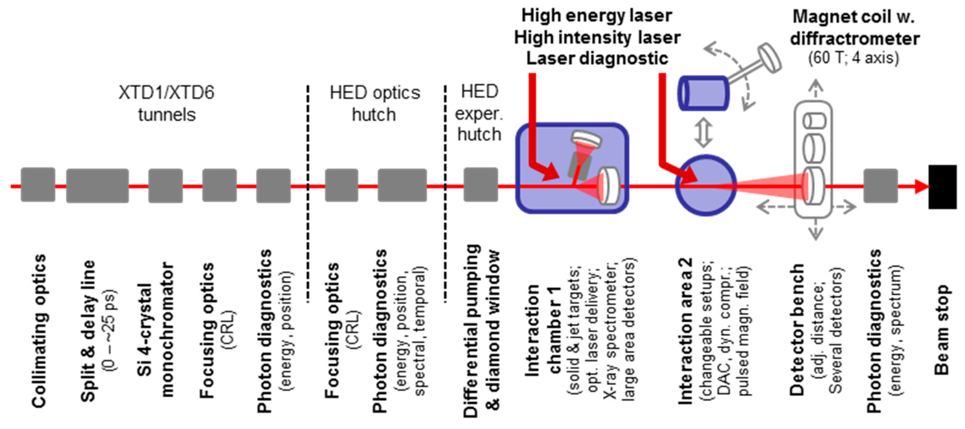
10. The HED Instrument

10.1. Scientific Scope and X-ray Techniques

The High-Energy Density (HED) instrument aims at the investigation of matter at extreme states of temperature, pressure, density, and/or electromagnetic fields using hard X-ray FEL radiation. For this goal the HED instrument will provide a unique combination of the drivers to create extreme states in the laboratory and hard X-ray laser pulses [120]. HED offers a wide range of time-resolved X-ray techniques reaching from diffraction, by imaging to different spectroscopy techniques for measuring various geometric and electronic structural properties. Research areas at HED include the investigation of properties of matter in solar and extra-solar planets, where high pressures of several 100 GPa at moderate temperatures (<10,000 K) are expected, and of properties of matter in the presence of both strong electric and magnetic fields. High-temperature superconductivity will be studied using pulsed magnetic fields generated in coils with field strengths up to 60 T. Extreme electromagnetic fields also occur during and after the interaction of short-pulse high-intensity lasers with solids and liquids, forming a dense plasma and accelerating electrons to up to several MeV kinetic energy. These induce very intense, transient magnetic fields, which could shed light on properties of matter at temperatures of several kT (~11,000 K).

10.2. Requirements

The use of a large variety of X-ray techniques creates a broad band of requirements to FEL operation and properties. Most important are the need for a small bandwidth, typically smaller than 10−4 in order to perform inelastic scattering experiments with sufficient resolution and throughput. Furthermore, as many experiments study or use low cross-section processes, high pulse energies are very important. This becomes particularly relevant for experiments at the highest photon energies above 20 keV. For experiments using high energy drivers to create extreme states and operating at reduced repetition rates of 1 Hz, or even far below, it is conceivable to switch beam to other stations at this FEL. Such an operation mode, however, requires that the experiments use the same, or at least very similar, X-ray properties.

10.3. HED Instrumentation and Capabilities

The HED instrument is installed at the SASE2 beamline and features an optics hutch (OH) and an experiment hutch (EH). In addition, an X-ray monochromator, focusing devices, a split and delay line optics and a pulse picker are placed inside the preceding tunnel section (see Figure 9). The four-bounce Si-(111) monochromator can reduce the SASE bandwidth to ∆E/E ~ 10−4 at 5–25 keV, while a high-resolution Si-(533) monochromator will allow for a 5 × 10⁻⁶ bandwidth at 7.5 keV. Focusing of 5–25 keV X-rays to foci of 1–200 µm at the sample position is established by several sets of Be compound refractive lenses (CRLs), located in the tunnel section (2×) and in OH. A fourth lens set close to the sample position will allow for sub-micron foci. A multilayer-based split-and-delay line has been designed, was constructed by the University of Münster (Germany) and is currently installed at HED [121]. This device allows splitting the X-ray pulse into two with a tunable intensity ratio and to separate them with a maximum delay of 2 ps (at 20 keV) and 23 ps (at 5 keV). A pulse picker will allow selecting X-ray pulses for 10 Hz, 1 Hz or pulse-on-demand operation, thereby synchronizing X-ray and optical laser delivery to the sample.
Power slits in OH can tailor the wings of the beam monitored by a beam-imaging unit. Using diamond gratings in first order a fraction of the incident beam can be steered to a single-pulse spectrometer using a bent Si crystal to monitor the incident X-ray spectrum. X-ray beam position and intensity are monitored by two intensity-position monitors, using backscattering from thin foils. Alternatively, real-time intensity monitoring is possible with a scintillator-coupled fast-frame CCD which picks up the other 1st order diffraction from the diamond grating. The quality of the photon beam can be further improved by cleanup slits for both high and low photon energies, located close to the interaction chamber in EH.
The 9 × 11 m2 experiment hutch is enclosed by a heavy concrete wall of thicknesses between 0.5 and 1.0 m to establish radiation shielding for high energetic electrons generated by the relativistic laser–matter interaction processes when focusing the multi-100 TW laser on the sample. In EH two interaction areas IA1 and IA2 have been defined. In IA1, a large vacuum interaction chamber (IC1) with inner dimensions 2.6 × 1.7 × 1.5 m3 (LWH) accommodates several configurations for diffraction, imaging or low/high resolution spectroscopy and inelastic X-ray scattering. The IC1 vacuum of ~10−4 mbar is separated from the X-ray optics by differential pumping stage or, above 10 keV, by a diamond window. At IA2 various setups can be interchanged. A second interaction chamber (IC2) with 1 m diameter is dedicated to dynamic diamond anvil cell (DAC) experiments and high-precision dynamic laser compression experiments in a standardized configuration. Alternatively, a goniometer with a pulsed magnetic coil and a cryogenic sample environment shall be placed here. While in IA1 all X-ray and laser beams are available, IA2 has access to the X-ray FEL and the nanosecond laser beams only.
X-ray detectors inside IC1 need to be vacuum-compatible with compact dimensions, low weight, modular assembly, and >10 Hz repetition rate. HED plans to have several detectors installed. Two EPIX100 modules [122] offer a 35 × 38 mm2 chip with 50 µm pixel pitch and 102 dynamic range at 8 keV. These detectors will be coupled, e.g., to crystal spectrometers. Three EPIX10k modules [123] have identical chip size, 100 µm pixel pitch, but offer 104 dynamic range by gain switching. With the same dynamic range, four Jungfrau modules offer 40 × 80 mm2 chips each with 75 µm pixel pitch and 104 dynamic range at 12 keV [124]. The latter two gain-switching detectors are ideally suited to record dedicated parts of an X-ray diffraction pattern. For both, IA1 and IA2, a detector bench at the end of EH will offer a possibility to place large area detectors, e.g., for imaging or SAXS type experiments. This bench allows adjusting the distance from IA1 and IA2 to the detector. On this bench, the HIBEF consortium plans to integrate an AGIPD 1M detector [31], a Perkin-Elmer 4343CT flat-panel large-area detector, and high-resolution CCD cameras for X-ray phase contrast imaging and ptychography applications.
Several drivers to generate extreme states of matter will be available at HED, e.g., two high energy optical lasers, diamond anvil cells, and pulsed magnetic fields, contributed and operated by the international HIBEF user consortium. The all-diode pumped high energy (HE) nanosecond DiPOLE-100X laser is developed by STFC CLF (UK) [125]. It delivers up to 80 J at 515 nm wavelength with pulse durations of 2–15 ns with a maximum repetition rate of 10 Hz. This laser will be primarily used for shock compression experiments and its pulses can be temporally shaped to enable isentropic ramp compression techniques. The multi-100 TW Ti:Sapphire (HI) laser system, currently under construction by Amplitude (France), will deliver 4–10 J of 800 nm light in ultrashort pulses of less than 25 fs at a repetition rate of 10 Hz. The pulses of this laser can be focused to a few µm2 spot by means of an off-axis parabola, reaching on-target intensities of the order of 1020 W/cm2. This laser will primarily be used for relativistic laser–matter interaction experiments. In addition, the standard PP laser of the European XFEL will be available. All three lasers have to be precisely timed with respect to the X-ray pulses and are synchronized to the master oscillator. The timing jitter between the PP laser and the incident X-rays is monitored by photon-arrival diagnostics with a precision on the order of a few femtoseconds. Timing between the HI laser and the X-rays is realized indirectly using the characterized PP laser in an optical-optical balanced cross-correlator. Timing between the HE laser and the X-rays is less demanding and achieved via fast photo diodes that detect both X-rays and optical light with a resolution of few 10 ps. Matter in magnetic fields of up to 60 T can be studied in a solenoid coil. The timescale of the field build-up of 0.6 ms is perfectly adapted to the length of a 4.5 MHz pulse train of the facility.

11. Future Developments

Being a brand new facility and observing much progress in the field of FEL sources, FEL instrumentation, and novel types of scientific experiments, a rich variety of further developments is expected to be implemented during the coming years. Developments going beyond the baseline scope of European XFEL have already started using external funding. Most notable is the construction and implementation of self-seeding for the hard X-ray FEL sources [104,105]. This is on-going for the SASE2 FEL and under preparation for SASE1. The FEL radiation performances of SASE3 would benefit enormously by the provision of variable polarization that can be switched between linear and circular with full flexibility [56]. The installation of an SASE3 afterburner is therefore under preparation. This afterburner consists of several 2 m long APPLE-type undulators, which will be added to the main SASE3 undulator. Furthermore, the installation of a chicane in the SASE3 undulator will enable operation at two widely separated photon energies for time-resolved X-ray–X-ray pump-probe investigations. Another development concerns the construction of additional scientific instruments. Using funds from user consortia, the additional end-station at SPB/SFX for serial femtosecond crystallography and a third beam transport system, vacuum port and experiment hutch at SASE3 are pursued. A completely different area is that of further developing the PP laser towards providing much longer wavelengths. Pumping solids in the THz regime has many scientific applications and is vigorously requested by part of the user community. The feasibility and possible implementation of laser- and accelerator-based techniques to produce intense, ultrashort duration, and monochromatic THz pulses is currently studied.
Naturally, the completion of the remaining two yet unoccupied FEL sources and the construction of further scientific instruments are expected to become major activities of European XFEL once the regular operation of the facility is achieved successfully. In a more distant future, a modification of the superconducting accelerator to include a cw mode of operation is very interesting for scientific applications, as is also indicated by the LCLS-II project [13]. Such an upgrade first requires developing an additional low emittance injector operating in cw mode. Since the electron energy will be significantly smaller than with the present pulsed RF system, this upgrade also requires a modified concept for the FEL sources. One possibility would be to direct the electrons to a second switchyard with novel FEL undulators specifically designed for the smaller electron energies and providing at the same time space for a second experiment hall hosting additional scientific instruments.

Acknowledgments

All contributors, both internal and external, to European XFEL are acknowledged for their outstanding contributions to build this facility. Additional instrumentation for the scientific instruments and the laboratory infrastructure provided through external contributions, in particular by the HIBEF, hRIXS, COMO, SFX and XBI User Consortia, and through BMBF Verbundforschung projects 05K10PM2, 05K13RF4, 05K16BC1, 05K16PE1 and 05K13PE2 is most gratefully acknowledged.

Author Contributions

Thomas Tschentscher conceived the article, Christian Bressler, Jan Grünert, Anders Madsen, Adrian P. Mancuso, Michael Meyer, Andreas Scherz, Harald Sinn and Ulf Zastrau contributed sections to this paper.

Conflicts of Interest

The authors declare no conflict of interest.

References

  1. Pellegrini, C.; Marinelli, A.; Reiche, S. The physics of X-ray free-electron lasers. Rev. Mod. Phys. 2016, 88, 015006. [Google Scholar] [CrossRef]
  2. Saldin, E.L.; Schneidmiller, E.V.; Yurkov, M.V. The Physics of Free-Electron Lasers, 1st ed.; Springer: Berlin, Germany, 1999. [Google Scholar]
  3. Ayvazyan, V.; Baboi, N.; Bähr, J.; Balandin, V.; Beutner, B.; Brandt, A.; Bohnet, I.; Bolzmann, A.; Brinkmann, R.; Brovko, O.I.; et al. First operation of a free-electron laser generating GW power radiation at 32 nm wavelength. Eur. Phys. J. D 2006, 37, 297–303. [Google Scholar] [CrossRef]
  4. Ackermann, W.; Asova, G.; Ayvazyan, V.; Azima, A.; Baboi, N.; Bähr, J.; Balandin, V.; Beutner, B.; Brandt, A.; Bolzmann, A.; et al. Operation of a free-electron laser from the extreme ultraviolet to the water window. Nat. Photonics 2007, 1, 336–342. [Google Scholar] [CrossRef]
  5. Emma, P.; Akre, R.; Arthur, J.; Bionta, R.; Bostedt, C.; Bozek, J.; Brachmann, A.; Bucksbaum, P.; Coffee, R.; Decker, F.-J.; et al. First lasing and operation of an Angstrom-wavelength free-electron laser. Nat. Photonics 2010, 4, 641–647. [Google Scholar] [CrossRef]
  6. Allaria, E.; Appio, R.; Badano, L.; Barletta, L.W.; Bassanese, S.; Biedron, S.G.; Borga, A.; Busetto, E.; Castronovo, D.; Cinquegrana, P.; et al. Highly coherent and stable pulses from the FERMI seeded free-electron laser in the extreme ultraviolet. Nat. Photonics 2012, 6, 699–704. [Google Scholar] [CrossRef]
  7. Ishikawa, T.; Aoyagi, H.; Asaka, T.; Asano, Y.; Azumi, Y.; Bizen, T.; Ego, H.; Fukami, K.; Fukui, T.; Furukawa, Y.; et al. A compact X-ray free-electron laser emitting in the sub-Ångström region. Nat. Photonics 2012, 6, 540–544. [Google Scholar] [CrossRef]
  8. Ko, I.S.; Kang, H.-S.; Heo, H.; Kim, C.; Kim, G.; Min, C.-K.; Yang, H.; Baek, S.Y.; Choi, H.-J.; Mun, G.; et al. Construction and Commissioning of PAL-XFEL Facility. Appl. Sci. 2017, 7, 479. [Google Scholar] [CrossRef]
  9. Patterson, B.D.; Abela, R.; Braun, H.-H.; Flechsig, U.; Ganter, R.; Kim, Y.; Kirk, E.; Oppelt, A.; Pedrozzi, M.; Reiche, S.; et al. Coherent science at the SwissFEL X-ray laser. New J. Phys. 2010, 12, 035012. [Google Scholar] [CrossRef]
  10. Altarelli, M.; Brinkmann, R.; Chergui, M.; Decking, W.; Dobson, B.; Düsterer, S.; Grübel, G.; Graeff, W.; Graafsma, H.; Hajdu, J.; et al. (Eds.) XFEL: The European X-ray Free-Electron Laser—Technical Design Report; DESY 2006-097; DESY: Hamburg, Germany, 2006. [Google Scholar] [CrossRef]
  11. Altarelli, A. The European X-ray free-electron laser facility in Hamburg. Nucl. Instrum. Methods Phys. Res. B 2011, 269, 2845–2849. [Google Scholar] [CrossRef]
  12. Flöttmann, K.; Rossbach, J.; Schmüser, P.; Walker, N.; Weise, H.; Brinkmann, R. (Eds.) TESLA Technical Design Report—Part II: The Accelerator; DESY 2001-011; DESY: Hamburg, Germany, 2001. [Google Scholar]
  13. Galayda, J.N. The New LCLS-II project: Status and Challenges. In Proceedings of the LINAC 2014 Conference, Geneva, Switzerland, 31 August–5 September 2014. [Google Scholar]
  14. Brinkmann, R.; Faatz, B.; Flöttmann, K.; Rossbach, J.; Schneider, J.R.; Schulte-Schrepping, H.; Trines, D.; Tschentscher, Th.; Weise, H. (Eds.) Design Report: First Stage of the TESLA XFEL Laboratory; DESY 2002-167; DESY: Hamburg, Germany, 2002. [Google Scholar]
  15. Decking, W.; Limberg, T. European XFEL Post-TDR Description; XFEL.EU TN-2013-004; European XFEL: Hamburg, Germany, 2013. [Google Scholar]
  16. Vartanyants, I.A.; Robinson, I.K.; McNulty, I.; David, C.; Wochner, P.; Tschentscher, Th. Coherent X-ray scattering and lensless imaging at the European XFEL Facility. J. Synchrotron Radiat. 2007, 14, 453–470. [Google Scholar] [CrossRef] [PubMed]
  17. Kimberg, V.; Sanchez-Gonzalez, A.; Mercadier, L.; Weninger, C.; Lutman, A.; Ratner, D.; Coffee, R.; Bucher, M.; Mucke, M.; Agaker, M.; et al. Stimulated X-ray Raman scattering—A critical assessment of the building block of nonlinear X-ray spectroscopy. Faraday Discuss. 2016, 194, 305–324. [Google Scholar] [CrossRef] [PubMed]
  18. Grübel, G.; Stephenson, G.B.; Gutt, C.; Sinn, H.; Tschentscher, Th. XPCS at the European X-ray free electron laser facility. Nucl. Instrum. Methods Phys. Res. B 2007, 262, 357–367. [Google Scholar] [CrossRef]
  19. Krasilnikov, M.; Stephan, F.; Asova, G.; Grabosch, H.-J.; Groß, M.; Hakobyan, L.; Isaev, I.; Ivanisenko, Y.; Jachmann, L.; Khojoyan, M.; et al. Experimentally minimized beam emittance from an L-band photoinjector. Phys. Rev. ST Accel. Beams 2012, 15, 100701. [Google Scholar] [CrossRef]
  20. Rimjaem, S.; Stephan, F.; Krasilnikov, M.; Ackermann, W.; Asova, G.; Bähr, J.; Gjonaj, E.; Grabosch, H.J.; Hakobyan, L.; Hänel, M.; et al. Optimizations of transverse projected emittance at the photo-injector test facility at DESY, location Zeuthen. Nucl. Instrum. Methods Phys. Res. A 2012, 671, 62–75. [Google Scholar] [CrossRef]
  21. Brinker, F. Commissioning of the European XFEL Injector. In Proceedings of the 7th International Particle Accelerator Conference (IPAC’16), Busan, Korea, 8–13 May 2016. [Google Scholar]
  22. Decking, W.; Weise, H. Commissioning of the European XFEL. In Proceedings of the International Particle Accelerator Conference 2017, Copenhagen, Denmark, 14–19 May 2017. [Google Scholar]
  23. Nölle, D. Commissioning of the European XFEL Facility. In Proceedings of the SPIE, X-ray Free-Electron Lasers: Advances in Source Development and Instrumentation, Prague, Czech Republic, 24–27 April 2017; Volume 10237. [Google Scholar]
  24. Li, Y.; Abeghyan, S.; Berndgen, K.; Baha-Shanjani, M.; Deron, G.; Englisch, U.; Karabekyan, S.; Ketenoglu, B.; Knoll, M.; Wolff-Fabris, F.; et al. Magnetic Measurement Techniques for the Large-Scale Production of Undulator Segments for the European XFEL. Synchrotron Radiat. News 2015, 28, 23–28. [Google Scholar] [CrossRef]
  25. Pflüger, J.; Lu, H.; Teichmann, T. Field fine tuning by pole height adjustment for the undulator of the TTF-FEL. Nucl. Instrum. Methods Phys. Res. A 1999, 429, 386–391. [Google Scholar] [CrossRef]
  26. Schneidmiller, E.A.; Yurkov, M.V. An Overview of the Radiation Properties of the European XFEL. In Proceedings of the FEL 2014 Conference, Basel, Switzerland, 5–29 August 2014. [Google Scholar]
  27. Schneidmiller, E.A.; Yurkov, M.V. Photon Beam Properties at the European XFEL, December 2010 Revision ed; Preprint DESY 11-152; DESY: Hamburg, Germany, 2011. [Google Scholar]
  28. Kuster, M.; Boukhelef, D.; Donato, M.; Dambietz, J.-S.; Hauf, S.; Maia, L.; Raab, N.; Szuba, J.; Turcato, M.; Wrona, K.; et al. Detectors and Calibration Concept for the European XFEL. Synchrotron Radiat. News 2014, 27, 35–38. [Google Scholar] [CrossRef]
  29. Raab, N.; Ballak, K.-E.; Dietze, T.; Ekmedzic, M.; Hauf, S.; Januschek, F.; Kaukher, A.; Kuster, M.; Lang, P.M.; Münnich, A.; et al. Status of the laboratory infrastructure for detector calibration and characterization at the European XFEL. J. Instrum. 2016, 11, C12051. [Google Scholar] [CrossRef]
  30. Mozzanica, A.; Bergamaschi, A.; Dinapoli, R.; Graafsma, H.; Greiffenberg, D.; Henrich, B.; Johnson, I.; Lohmann, M.; Valeria, R.; Schmitt, B. The GOTTHARD charge integrating readout detector: Design and characterization. J. Instrum. 2012, 7, C01019. [Google Scholar] [CrossRef]
  31. Henrich, B.; Becker, J.; Dinapoli, R.; Goettlicher, P.; Graafsma, H.; Hirsemann, H.; Klanner, R.; Krueger, H.; Mazzocco, R.; Mozzanica, A.; et al. The adaptive gain integrating pixel detector AGIPD a detector for the European XFEL. Nucl. Instrum. Methods Phys. Res. A 2011, 633, S11–S14. [Google Scholar] [CrossRef]
  32. Koch, A.; Hart, M.; Nicholls, T.; Angelsen, C.; Coughlan, J.; French, M.; Hauf, S.; Kuster, M.; Sztuk-Dambietz, J.; Turcato, M.; et al. Performance of an LPD prototype detector at MHz frame rates under Synchrotron and FEL radiation. J. Instrum. 2013, 8, C11001. [Google Scholar] [CrossRef]
  33. Porro, M.; Andricek, L.; Bombelle, L.; De Vita, G.; Fiorini, C.; Fischer, P.; Hansen, K.; Lechner, P.; Lutz, G.; Strüder, L.; et al. Expected performance of the DEPFET sensor with signal compression: A large format X-ray imager with mega-frame readout capability for the European XFEL. Nucl. Instrum. Methods Phys. Res. A 2010, 624, 509–519. [Google Scholar] [CrossRef]
  34. Pergament, M.; Kellert, M.; Kruse, K.; Wang, J.; Palmer, G.; Wissmann, L.; Wegner, U.; Lederer, M.J. High power burst-mode optical parametric amplifier with arbitrary pulse selection. Opt. Express 2014, 22, 22202–22210. [Google Scholar] [CrossRef] [PubMed]
  35. Pergament, M.; Palmer, G.; Kellert, M.; Kruse, K.; Wang, J.; Wissmann, L.; Wegner, U.; Emons, M.; Kane, D.; Priebe, G.; et al. Versatile optical laser system for experiments at the European X-ray Free-Electron Laser Facility. Opt. Express 2016, 24, 29349–29359. [Google Scholar] [CrossRef] [PubMed]
  36. Sydlo, C.; Czwalinna, M.; Felber, M.; Gerth, C.; Jabłoński, S.; Müller, J.; Schlarb, H.; Zummack, F. Femtosecond Timing Distribution at the European XFEL. In Proceedings of the 7th International Particle Accelerator Conference (IPAC’16), Busan, Korea, 8–13 May 2016. [Google Scholar]
  37. Schulz, S.; Grguras, I.; Behrens, C.; Bromberger, H.; Costello, J.T.; Czwalinna, M.K.; Felber, M.; Hoffmann, M.C.; Ilchen, M.; Liu, H.Y.; et al. Femtosecond all-optical synchronization of an X-ray free-electron laser. Nat. Commun. 2015, 6, 5938. [Google Scholar] [CrossRef] [PubMed]
  38. Sinn, H.; Gaudin, J.; Samoylova, L.; Trapp, A; Galasso, G. Conceptual Design Report: X-ray Optics and Beam Transport; XFEL.EU TR-2011-002; European XFEL: Hamburg, Germany, 2011. [Google Scholar] [CrossRef]
  39. Sinn, H.; Dommach, M.; Dong, X.; La Civita, D.; Samoylova, L.; Villanueva, R.; Yang, F. Technical Design Report: X-ray Optics and Beam Transport; XFEL.EU TR-2012-006; European XFEL: Hamburg, Germany, 2012. [Google Scholar] [CrossRef]
  40. Geloni, G.; Saldin, E.; Samoylova, L.; Schneidmiller, E.; Sinn, H.; Tschentscher, Th.; Yurkov, M. Coherence properties of the European XFEL. New J. Phys. 2010, 12, 035021. [Google Scholar] [CrossRef]
  41. Grünert, J. Conceptual Design Report: Framework for X-ray Photon Diagnostics at the European XFEL; XFEL.EU TR-2012-003; European XFEL: Hamburg, Germany, 2012. [Google Scholar] [CrossRef]
  42. Grünert, J.; Buck, J.; Ozkan, C.; Freund, W.; Molodtsov, S. X-ray Photon Diagnostics Devices for the European XFEL. In Proceedings of the SPIE, X-ray Free-Electron Lasers: Beam Diagnostics, Beamline Instrumentation, and Applications, San Diego, CA, USA, 12 August 2012. [Google Scholar] [CrossRef]
  43. Grünert, J.; Buck, J.; Freund, W.; Ozkan, C.; Molodtsov, S. Development status of the X-ray beam diagnostics devices for the commissioning and user operation of the European XFEL. J. Phys. Conf. Ser. 2013, 425, 072004. [Google Scholar] [CrossRef]
  44. Gruenert, J.; Koch, A.; Kujala, N.; Freund, V.; Planas, M.; Dietrich, F.; Buck, J.; Liu, J.; Sinn, H.; Dommach, M. Photon Diagnostics and Photon Beamlines Installations at the European XFEL. In Proceedings of the 37th International Free-Electron Laser Conference 2015, Daejeon, Korea, 23–28 August 2015. [Google Scholar]
  45. Liu, J. Requirements and Concept for the Characterization of Photon Beam Temporal Properties at the SQS Scientific Instrument of the European XFEL Facility; XFEL.EU TN-2015-002-01; European XFEL: Hamburg, Germany, 2015. [Google Scholar]
  46. Liu, J.; Dietrich, F.; Grünert, J. Technical Design Report: Photon Arrival Time Monitor (PAM) at the European XFEL; XFEL.EU TR-2017-002; European XFEL: Schenefeld, Germany, 2017. [Google Scholar]
  47. Maltezopoulos, Th.; Cunovic, S.; Wieland, M.; Beye, M.; Azima, A.; Redlin, H.; Krikunova, M.; Kalms, R.; Frühling, U.; Budzyn, F.; et al. Single-shot timing measurement of extreme-ultraviolet free-electron laser pulses. New J. Phys. 2008, 10, 033026. [Google Scholar] [CrossRef]
  48. Grguras, I.; Maier, A.R.; Behrens, C.; Mazza, T.; Kelly, T.J.; Radcliffe, P.; Düsterer, S.; Kazansky, A.K.; Kabachnik, N.M.; Tschentscher, Th.; et al. Ultrafast X-ray pulse characterization at free-electron lasers. Nat. Photonics 2012, 6, 852–857. [Google Scholar] [CrossRef]
  49. Harmand, M.; Coffee, R.; Bionta, M.R.; Chollet, M.; French, D.; Zhu, D.; Fritz, D.M.; Lemke, H.T.; Medvedev, N.; Ziaja, B.; et al. Achieving few-femtosecond time-sorting at hard X-ray free-electron lasers. Nat. Photonics 2013, 7, 215–218. [Google Scholar] [CrossRef]
  50. Hartmann, N.; Helml, W.; Galler, A.; Bionta, M.R.; Grünert, J.; Molodtsov, S.L.; Ferguson, K.R.; Schorb, S.; Swiggers, M.L.; Carron, S.; et al. Sub-femtosecond precision measurement of relative X-ray arrival time for free-electron lasers. Nat. Photonics 2014, 8, 706–709. [Google Scholar] [CrossRef]
  51. Tiedtke, K.; Feldhaus, J.; Hahn, U.; Jastrow, U.; Nunez, T.; Tschentscher, Th.; Bobashev, S.V.; Sorokin, A.A.; Hastings, J.B.; Möller, S.; et al. Gas-detector for X-ray lasers. J. Appl. Phys. 2008, 103, 094511. [Google Scholar] [CrossRef]
  52. Feng, Y.; Raubenheimer, T.O. Duty-Cycle Dependence of the Filamentation Effect in Gas Devices for High Repetition Rate Pulsed X-ray FEL’s. In Proceedings of the SPIE, X-ray Free-Electron Lasers: Advances in Source Development and Instrumentation, Prague, Czech Republic, 24–27 April 2017; Volume 10237. [Google Scholar]
  53. Tono, K.; Kudo, T.; Yabashi, M.; Tachibana, T.; Feng, Y.; Fritz, D.; Hastings, J.; Ishikawa, T. Single-shot beam-position monitor for X-ray free electron laser. Rev. Sci. Instrum. 2011, 82, 023108. [Google Scholar] [CrossRef] [PubMed]
  54. Zhu, D.; Cammarata, M.; Feldkamp, J.M.; Fritz, D.M.; Hastings, J.B.; Lee, S.; Lemke, H.T.; Robert, A.; Turner, J.L.; Feng, Y. A single-shot transmissive spectrometer for hard X-ray free electron lasers. Appl. Phys. Lett. 2012, 101, 034103. [Google Scholar] [CrossRef]
  55. Buck, J. Conceptual Design Report: Online Time-of-Flight Photoemission Spectrometer for X-ray Photon Diagnostics; XFEL.EU TR-2012-002; European XFEL: Hamburg, Germany, 2012. [Google Scholar] [CrossRef]
  56. Lutman, A.A.; MacArthur, J.P.; Ilchen, M.; Lindahl, A.O.; Buck, J.; Coffee, R.N.; Dakovski, G.L.; Dammann, L.; Ding, Y.; Dürr, H.A.; et al. Polarization control in an X-ray free-electron laser. Nat. Photonics 2016, 10, 468–472. [Google Scholar] [CrossRef]
  57. Syresin, E.; Brovko, O.; Kapishin, M.; Shabunov, A.; Yurkov, M.; Freund, W.; Gruenert, J.; Sinn, H. Development of MCP Based Photon Detectors for the European XFEL. In Proceedings of the International Particle Accelerator Conference 2011, San Sebastian, Spain, 4–9 September 2011. [Google Scholar]
  58. Freund, W. The Undulator Commissioning Spectrometer for the European XFEL, XFEL.EU Technical Report; XFEL.EU TN-2014-001-01; European XFEL: Hamburg, Germany, 2013. [Google Scholar]
  59. Ozkan, C.; Freund, W.; Rehanek, J.; Buck, J.; Zizak, I.; Gruenert, J.; Schaefers, F.; Erko, A.; Molodtsov, S. Initial Evaluation of the European XFEL Undulator Commissioning Spectrometer with a Single Channel-Cut Crystal. In Proceedings of the SPIE, X-ray Free-Electron Lasers: Beam Diagnostics, Beamline Instrumentation, and Applications, San Diego, CA, USA, 12 August 2012; Volume 8504. [Google Scholar] [CrossRef]
  60. Ozkan, C. Conceptual Design Report: Imaging Stations for Invasive Photon Diagnostics; XFEL.EU TR-2012-004; European XFEL: Hamburg, Germany, 2012. [Google Scholar]
  61. Mancuso, A.P.; Aquila, A.L.; Borchers, G.; Giewekemeyer, K.; Reimers, N. Technical Design Report: Scientific Instrument Single Particles, Clusters, and Biomolecules (SPB); XFEL.EU TR-2013-004; European XFEL: Hamburg, Germany, 2013. [Google Scholar] [CrossRef]
  62. Garman, E.F. Developments in X-ray Crystallographic Structure Determination of Biological Macromolecules. Science 2014, 343, 1102–1108. [Google Scholar] [CrossRef] [PubMed]
  63. Spence, J.C.H.; Weierstall, U.; Chapman, H.N. X-ray lasers for structural and dynamic biology. Rep. Prog. Phys. 2012, 75, 102601. [Google Scholar] [CrossRef] [PubMed]
  64. Schlichting, I. Serial femtosecond crystallography: The first five years. IUCrJ 2015, 2, 246–255. [Google Scholar] [CrossRef] [PubMed]
  65. White, T.A.; Kirian, R.A.; Martin, A.V.; Aquila, A.; Nass, K.; Barty, A.; Chapman, H.N. CrystFEL: A software suite for snapshot serial crystallography. J. Appl. Crystallogr. 2012, 45, 335–341. [Google Scholar] [CrossRef]
  66. Loh, N.-T.D.; Elser, V. Reconstruction algorithm for single-particle diffraction imaging experiments. Phys. Rev. E 2009, 80, 026705. [Google Scholar] [CrossRef] [PubMed]
  67. Barends, T.R.M.; Foucar, L.; Botha, S.; Doak, R.B.; Shoeman, R.L.; Nass, K.; Koglin, J.E.; Williams, G.J.; Boutet, S.; Messerschmidt, M.; et al. De novo protein crystal structure determination from X-ray free-electron laser data. Nature 2015, 505, 244–247. [Google Scholar] [CrossRef] [PubMed]
  68. Schwander, P.; Fung, R.; Phillips, G.N.; Ourmazd, A. Mapping the conformations of biological assemblies. New J. Phys. 2010, 12, 035007. [Google Scholar] [CrossRef]
  69. Aquila, A.; Sobierajski, R.; Ozkan, C.; Hajkova, V.; Burian, T.; Chalupský, J.; Juha, L.; Störmer, M.; Bajt, S.; Klepka, M.T.; et al. Fluence thresholds for grazing incidence hard X-ray mirrors. Appl. Phys. Lett. 2015, 106, 241905. [Google Scholar] [CrossRef]
  70. Bean, R.J.; Aquila, A.; Samoylova, L.; Mancuso, A.P. Design of the mirror optical systems for coherent diffractive imaging at the SPB/SFX instrument of the European XFEL. J. Opt. 2016, 18, 1–10. [Google Scholar] [CrossRef]
  71. Bressler, Ch.; Galler, A.; Gawelda, W. Technical Design Report: Scientific Instrument FXE; XFEL.EU TR-2012-008; European XFEL: Hamburg, Germany, 2012. [Google Scholar] [CrossRef]
  72. Cho, H.S.; Dashdorj, N.D.; Schotte, F.; Graber, T.; Henning, R.; Anfinrud, P. Protein structural dynamics in solution unveiled via 100-ps time-resolved X-ray scattering. Proc. Natl. Acad. Sci. USA 2010, 107, 7281–7286. [Google Scholar] [CrossRef] [PubMed]
  73. Brefuel, N.; Watanabe, H.; Toupet, L.; Come, J.; Matsumoto, N.; Collet, E.; Tanaka, K.; Tuchagues, J.P. Concerted Spin Crossover and Symmetry Breaking Yield Three Thermally and One Light-Induced Crystallographic Phases of a Molecular Material. Angew. Chem. Int. Ed. 2013, 48, 9304–9307. [Google Scholar] [CrossRef] [PubMed]
  74. Smolentsev, G.; Sundström, V. Time-resolved X-ray absorption spectroscopy for the study of molecular systems relevant for artificial photosynthesis. Coord. Chem. Rev. 2015, 304, 117–132. [Google Scholar] [CrossRef]
  75. Torres-Alacan, J.; Lindner, J.; Vöhringer, P. Probing the Primary Photochemical Processes of Octahedral Iron(V) Formation with Femtosecond Mid-Infrared Spectroscopy. Chem. Phys. Chem. 2015, 16, 2289–2293. [Google Scholar] [CrossRef] [PubMed]
  76. Zhang, W.; Alonso-Mori, R.; Bergmann, U.; Bressler, C.; Chollet, M.; Galler, A.; Gawelda, W.; Hadt, R.G.; Hartsock, R.W.; Kroll, T.; et al. Tracking excited-state charge and spin dynamics in iron coordination complexes. Nature 2014, 509, 345–348. [Google Scholar] [CrossRef] [PubMed]
  77. Haldrup, K.; Gawelda, W.; Abela, R.; Alonso-Mori, R.; Bergmann, U.; Bordage, A.; Cammarata, M.; Canton, S.; Dohn, A.O.; van Driel, T.B. Observing Solvatiuon Dynamics with Simultaneous Femtosecond X-ray Emission Spectroscopy and X-ray Scattering. J. Phys. Chem. B 2016, 120, 1158–1168. [Google Scholar] [CrossRef] [PubMed]
  78. Katayama, T.; Owada, S.; Togashi, T.; Ogawa, K.; Karvinen, P.; Vartiainen, I.; Eronen, A.; David, C.; Sato, T.; Nakajima, K.; et al. A beam branching method for timing and spectral characterization of hard X-ray free electron lasers. Struct. Dyn. 2016, 3, 034301. [Google Scholar] [CrossRef] [PubMed]
  79. Mazza, T.; Zhang, H.; Meyer, M. Technical Design Report: Scientific Instrument SQS; XFEL.EU TR-2012-007; European XFEL: Hamburg, Germany, 2012. [Google Scholar] [CrossRef]
  80. Ullrich, J.; Moshammer, R.; Dorn, A.; Dörner, R.; Schmidt, H.L.P.; Schmidt-Böcking, H. Recoil-ion and electron momentum spectroscopy reaction-microscopes. Rep. Prog. Phys. 2003, 66, 1463–1545. [Google Scholar] [CrossRef]
  81. De Jong, S.; Kukreja, R.; Trabant, C.; Pontius, N.; Chang, C.F.; Kachel, T.; Beye, M.; Sorgenfrei, F.; Back, C.H.; Bräuer, B.; et al. Speed limit of the insulator–metal transition in magnetite. Nat. Mater. 2013, 12, 882–886. [Google Scholar] [CrossRef] [PubMed]
  82. Kubacka, T.; Johnson, J.A.; Hoffmann, M.C.; Vicario, C.; de Jong, S.; Beaud, P.; Grübel, S.; Huang, S.-W.; Huber, L.; Patthey, L.; et al. Large-Amplitude Spin Dynamics Driven by a THz Pulse in Resonance with an Electromagnon. Science 2014, 343, 1333–1336. [Google Scholar] [CrossRef] [PubMed]
  83. Först, M.; Caviglia, A.D.; Scherwitzl, R.; Mankowsky, R.; Zubko, P.; Khanna, V.; Bromberger, H.; Wilkins, S.B.; Chuang, Y.-D.; Lee, W.S.; et al. Spatially resolved ultrafast magnetic dynamics initiated at a complex oxide heterointerface. Nat. Mater. 2015, 14, 883–888. [Google Scholar] [CrossRef] [PubMed]
  84. Graves, C.E.; Reid, A.H.; Wang, T.; Wu, B.; de Jong, S.; Vahaplar, K.; Radu, I.; Bernstein, D.P.; Messerschmidt, M.; Müller, L.; et al. Nanoscale spin reversal by non-local angular momentum transfer following ultrafast laser excitation in ferrimagnetic GdFeCo. Nat. Mater. 2013, 12, 293–298. [Google Scholar] [CrossRef] [PubMed]
  85. Vodungbo, B.; Tudu, B.; Perron, J.; Delaunay, R.; Müller, L.; Berntsen, M.H.; Grübel, G.; Malinowski, G.; Weier, C.; Gautier, J.; et al. Indirect excitation of ultrafast demagnetization. Sci. Rep. 2016, 6, 18970. [Google Scholar] [CrossRef] [PubMed]
  86. Öström, H.; Öberg, H.; Xin, H.; LaRue, J.; Beye, M.; Dell’Angela, M.; Gladh, J.; Ng, M.L.; Sellberg, J.A.; Kaya, S.; et al. Probing the transition state region in catalytic CO oxidation on Ru. Science 2015, 347, 978–982. [Google Scholar] [CrossRef] [PubMed]
  87. Wernet, Ph.; Kunnus, K.; Josefsson, I.; Rajkovic, I.; Quevedo, W.; Beye, M.; Schreck, S.; Grubel, S.; Scholz, M.; Nordlund, D.; et al. Orbital-specific mapping of the ligand exchange dynamics of Fe(CO)5 in solution. Nature 2015, 520, 78–81. [Google Scholar] [CrossRef] [PubMed]
  88. Beye, M.; Schreck, S.; Sorgenfrei, F.; Trabant, C.; Pontius, N.; Schüßler-Langeheine, C.; Wurth, W.; Fohlisch, A. Stimulated X-ray emission for materials science. Nature 2013, 501, 191–194. [Google Scholar] [CrossRef] [PubMed]
  89. Higley, D.J.; Hirsch, K.; Dakovski, G.L.; Jal, E.; Yuan, E.; Liu, T.; Lutman, A.A.; MacArthur, J.P.; Arenholz, E.; Chen, Z.; et al. Femtosecond X-ray magnetic circular dichroism absorption spectroscopy at an X-ray free electron laser. Rev. Sci. Instrum. 2016, 87, 033110. [Google Scholar] [CrossRef] [PubMed]
  90. Eisebitt, S.; Luning, J.; Schlotter, W.F.; Lorgen, M.; Hellwig, O.; Eberhardt, W.; Stohr, J. Lensless imaging of magnetic nanostructures by X-ray spectro-holography. Nature 2004, 432, 885–888. [Google Scholar] [CrossRef] [PubMed]
  91. Liu, T.-M.; Wang, T.; Reid, A.H.; Savoini, M.; Wu, X.; Koene, B.; Granitzka, P.; Graves, C.E.; Higley, D.J.; Chen, Z.; et al. Nanoscale Confinement of All-Optical Magnetic Switching in TbFeCo—Competition with Nanoscale Heterogeneity. Nano Lett. 2015, 15, 6862–6868. [Google Scholar] [CrossRef] [PubMed]
  92. Scherz, A.; Krupin, O.; Buck, J.; Gerasimova, N.; Palmer, G.; Poolton, N.; Samoylova, L. Conceptual Design Report: Scientific Instrument Spectroscopy and Coherent Scattering (SCS); XFEL.EU TR-2013-006; European XFEL: Hamburg, Germany, 2013. [Google Scholar] [CrossRef]
  93. Wang, T.; Zhu, D.; Wu, B.; Graves, C.; Schaffert, S.; Rander, T.; Müller, L.; Vodungbo, B.; Baumier, C.; Bernstein, D.P.; et al. Femtosecond Single-Shot Imaging of Nanoscale Ferromagnetic Order in Co/Pd Multilayers Using Resonant X-ray Holography. Phys. Rev. Lett. 2012, 108, 267403. [Google Scholar] [CrossRef] [PubMed]
  94. Miao, J.; Ishikawa, T.; Robinson, I.K.; Murnane, M.M. Beyond crystallography: Diffractive imaging using coherent X-ray light sources. Science 2015, 348, 530–535. [Google Scholar] [CrossRef] [PubMed]
  95. Clark, J.; Beitra, L.; Xiong, G.; Higginbotham, A.; Fritz, D.M.; Lemke, H.T.; Zhu, D.; Chollet, M.; Williams, G.J.; Messerschmidt, M.; et al. Ultrafast Three-Dimensional Imaging of Lattice Dynamics in Individual Gold Nanocrystals. Science 2013, 341, 56–59. [Google Scholar] [CrossRef] [PubMed]
  96. Madsen, A.; Fluerasu, A.; Ruta, B. Structural Dynamics of Materials Probed by X-ray Photon Correlation Spectroscopy. In Synchrotron Light Sources and Free-Electron Lasers. Accelerator Physics, Instrumentation and Science Applications, 1st ed.; Jaeschke, E., Khan, S., Schneider, J.R., Hastings, J.B., Eds.; Springer: Berlin, Germany, 2016; pp. 1617–1641. [Google Scholar]
  97. Carnis, J.; Cha, W.; Wingert, J.; Kang, J.; Jiang, Z.; Song, S; Sikorski, M.; Robert, A.; Gutt, C.; Chen, S.-W.; et al. Demonstration of Feasibility of X-ray Free Electron Laser Studies of Dynamics of Nanoparticles in Entangled Polymer Melts. Sci. Rep. 2014, 4, 6017. [Google Scholar] [CrossRef] [PubMed]
  98. Lehmkühler, F.; Kwasniewski, P.; Roseker, W.; Fischer, B.; Schroer, M.A.; Tono, K.; Katayama, T.; Sprung, M.; Sikorski, M.; Song, S.; et al. Sequential Single Shot X-ray Photon Correlation Spectroscopy at the SACLA Free Electron Laser. Sci. Rep. 2015, 5, 17193. [Google Scholar] [CrossRef] [PubMed]
  99. Singer, A.; Patel, S.K.K.; Kukreja, R.; Uhlir, V.; Wingert, J.; Festersen, S.; Zhu, D.; Glownia, J.M.; Lemke, H.T.; Nelson, S.; et al. Photoinduced Enhancement of the Charge Density Wave Amplitude. Phys. Rev. Lett. 2016, 117, 056401. [Google Scholar] [CrossRef] [PubMed]
  100. Trigo, M.; Fuchs, M.; Chen, J.; Jiang, M.P.; Cammarata, M.; Fahy, S.; Fritz, D.M.; Gaffney, K.; Ghimire, S.; Higginbotham, A.; et al. Fourier-transform inelastic X-ray scattering from time- and momentum-dependent phonon–phonon correlations. Nat. Phys. 2013, 9, 790. [Google Scholar] [CrossRef]
  101. Liang, M.; Williams, G.J.; Messerschmidt, M.; Seibert, M.M.; Montanez, P.A.; Hayes, M.; Milathianaki, D.; Aquila, A.; Hunter, M.S.; Koglin, J.S.; et al. The Coherent X-ray Imaging instrument at the Linac Coherent Light Source. J. Synchrotron Radiat. 2015, 22, 514. [Google Scholar] [CrossRef] [PubMed]
  102. Nagler, B.; Schropp, A.; Galtier, E.C.; Arnold, B.; Brown, S.B.; Fry, A.; Gleason, A.; Granados, E.; Hashim, A.; Hastings, J.B.; et al. The phase-contrast imaging instrument at the matter in extreme conditions endstation at LCLS. Rev. Sci. Instrum. 2016, 87, 103701. [Google Scholar] [CrossRef] [PubMed]
  103. Wochner, P.; Gutt, C.; Autenrieth, T.; Demmer, T.; Bugaev, V.; Ortiz, A.D.; Duri, A.; Zontone, F.; Grübel, G.; Dosch, H. X-ray cross correlation analysis uncovers hidden local symmetries in disordered matter. Proc. Natl. Acad. Sci. USA 2009, 106, 11511. [Google Scholar] [CrossRef] [PubMed]
  104. Geloni, G.; Kocharyan, V.; Saldin, E. A novel self-seeding scheme for hard X-ray FELs. J. Mod. Opt. 2011, 58, 1391. [Google Scholar] [CrossRef]
  105. Amann, J.; Berg, W.; Blank, V.; Decker, F.-J.; Ding, Y.; Emma, P.; Feng, Y.; Frisch, J.; Fritz, D.; Hastings, J.; et al. Demonstration of self-seeding in a hard-X-ray free-electron laser. Nat. Photonics 2012, 6, 693. [Google Scholar] [CrossRef]
  106. Chubar, O.; Geloni, G.; Kocharyan, V.; Madsen, A.; Saldin, E.; Serkez, S.; Shvyd’ko, Y.; Sutter, J. Ultra-high-resolution inelastic X-ray scattering at high-repetition-rate self-seeded X-ray free-electron lasers. J. Synchrotron Radiat. 2016, 23, 410. [Google Scholar] [CrossRef] [PubMed]
  107. Roseker, W.; Franz, H.; Schulte-Schrepping, H.; Ehnes, A.; Leupold, O.; Zontone, F.; Lee, S.; Robert, A.; Grübel, G. Development of a hard X-ray delay line for X-ray photon correlation spectroscopy and jitter-free pump–probe experiments at X-ray free-electron laser sources. J. Synchrotron Radiat. 2011, 18, 481. [Google Scholar] [CrossRef] [PubMed]
  108. Osaka, T.; Hirano, T.; Sano, Y.; Inubushi, Y.; Matsuyama, S.; Tono, K.; Ishikawa, T.; Yamauchi, K.; Yabashi, M. Wavelength-tunable split-and-delay optical system for hard X-ray free-electron lasers. Opt. Express 2016, 24, 9187. [Google Scholar] [CrossRef] [PubMed]
  109. Lu, W.; Noll, T.; Roth, T.; Agapov, I.; Geloni, G.; Holler, M.; Hallmann, J.; Ansaldi, G.; Eisebitt, S.; Madsen, A. Design and throughput simulations of a hard X-ray split and delay line for the MID station at the European XFEL. AIP Conf. Proc. 2016, 1741, 030010. [Google Scholar] [CrossRef]
  110. Gutt, C.; Stadler, L.-M.; Duri, A.; Autenrieth, T.; Leupold, O.; Chushkin, Y.; Grübel, G. Measuring temporal speckle correlations at ultrafast X-ray sources. Opt. Express 2009, 17, 55. [Google Scholar] [CrossRef] [PubMed]
  111. Bandyopadhyay, R.; Gittings, A.S.; Suh, S.S.; Dixon, P.K.; Durian, D.J. Speckle-visibility spectroscopy: A tool to study time-varying dynamics. Rev. Sci. Instrum. 2005, 76, 093110. [Google Scholar] [CrossRef]
  112. Van Thor, J.J.; Madsen, A. A split-beam probe-pump-probe scheme for femtosecond time resolved protein X-ray crystallography. Struct. Dyn. 2015, 2, 014102. [Google Scholar] [CrossRef] [PubMed]
  113. Madsen, A.; Hallmann, J.; Roth, T.; Ansaldi, G. Technical Design Report: Scientific Instrument MID; XFEL.EU TR-2013-005; European XFEL: Hamburg, Germany, 2013. [Google Scholar] [CrossRef]
  114. Roth, T.; Helfen, T.; Hallmann, J.; Samoylova, L.; Kwaśniewski, P.; Lengeler, B.; Madsen, A. X-ray Laminography and SAXS on Beryllium Grades and Lenses and Wavefront Propagation through Imperfect Compound Refractive Lenses. In Proceedings of the SPIE: Advances in X-ray/EUV Optics and Components IX, San Diego, CA, USA, 17 August 2014. [Google Scholar] [CrossRef]
  115. Shwartz, S.; Coffee, R.N.; Feldkamp, J.M.; Feng, Y.; Hastings, J.B.; Yin, G.Y.; Harris, S.E. X-ray Parametric Down-Conversion in the Langevin Regime. Phys. Rev. Lett. 2012, 109, 013602. [Google Scholar] [CrossRef] [PubMed]
  116. Temasaku, K.; Shigemasa, E.; Inubushi, Y.; Katayama, T.; Sawada, K.; Yumoto, H.; Ohashi, H.; Mimura, H.; Yabashi, M.; Yamauchi, K.; et al. X-ray two-photon absorption competing against single and sequential multiphoton processes. Nat. Photonics 2014, 8, 313. [Google Scholar] [CrossRef]
  117. Stöhr, J. Two-Photon X-ray Diffraction. Phys. Rev. Lett. 2017, 118, 024801. [Google Scholar] [CrossRef] [PubMed]
  118. Boesenberg, U.; Samoylova, L.; Roth, T.; Zhu, D.; Terentyev, S.; Vannoni, M.; Feng, Y.; van Driel, T.B.; Song, S.; Blank, V.; et al. X-ray spectrometer based on a bent diamond crystal for high repetition rate free-electron laser applications. Opt. Express 2017, 25, 2852. [Google Scholar] [CrossRef]
  119. Obara, Y.; Katayama, T.; Ogi, Y.; Suzuki, T.; Kurahashi, N.; Karashima, S.; Chiba, Y.; Isokawa, Y.; Togashi, T.; Inubushi, Y.; et al. Femtosecond time-resolved X-ray absorption spectroscopy of liquid using a hard X-ray free electron laser in a dual-beam dispersive detection method. Opt. Express 2014, 22, 1105. [Google Scholar] [CrossRef] [PubMed]
  120. Nakatsutsumi, M.; Appel, K.; Priebe, G.; Thorpe, I.; Pelka, A.; Muller, B.; Tschentscher, Th. Technical Design Report: Scientific Instrument High Energy Density Physics (HED); XFEL.EU TR-2014-001; European XFEL: Hamburg, Germany, 2014. [Google Scholar] [CrossRef]
  121. Roling, S.; Zacharias, H.; Samoylova, L.; Sinn, H.; Tschentscher, Th.; Chubar, O.; Buzmakov, A.; Schneidmiller, E.; Yurkov, M.V.; Siewert, F.; et al. Time-dependent wave front propagation simulation of a hard X-ray split-and-delay unit: Towards a measurement of the temporal coherence properties of X-ray free electron lasers. Phys. Rev. STAB 2014, 17, 110705. [Google Scholar] [CrossRef]
  122. Carini, G.A.; Alonso-Mori, R.; Blaj, G.; Caragiulo, P.; Chollet, M.; Damiani, D.; Dragone, A.; Feng, Y.; Haller, G.; Hart, P.; et al. ePix100 camera: Use and applications at LCLS. AIP Conf. Proc. 2016, 1741, 040008. [Google Scholar] [CrossRef]
  123. Nishimura, K.; Blaj, G.; Caragiulo, P.; Carini, G.A.; Dragone, A.; Haller, G.; Hart, P.; Hasi, J.; Herbst, R.; Herrmann, S.; et al. Design and performance of the ePix camera system. AIP Conf. Proc. 2016, 1741, 040047. [Google Scholar] [CrossRef]
  124. Mozzanica, A.; Bergamaschi, A.; Cartier, S.; Dinapoli, R.; Greiffenberg, D.; Johnson, I.; Jungmann, J.; Maliakal, D.; Mezza, D.; Ruder, C.; et al. Prototype characterization of the JUNGFRAU pixel detector for SwissFEL. J. Instrum. 2014, 9, C05010. [Google Scholar] [CrossRef]
  125. Banerjee, S.; Ertel, K.; Mason, P.D.; Phillips, P.J.; De Vido, M.; Smith, J.M.; Butcher, T.J.; Hernandez-Gomez, C.; Greenhalgh, R.J.S.; Collier, J.L. DiPOLE: A 10 J, 10 Hz cryogenic gas cooled multi-slab nanosecond Yb:YAG laser. Opt. Express 2015, 23, 19542–19551. [Google Scholar] [CrossRef] [PubMed]
Figure 1. Overall layout of the European XFEL facility. The electron accelerator leads into two electron beamlines with up to five FEL sources. Each of these has dedicated X-ray transport sections leading towards the experiment hall, where the up to fifteen scientific instruments can be installed. For abbreviations see text.
Applsci 07 00592 g001
Figure 2. Time pattern of the electron bunch train in the linac. The RF field is pulsed with 10 Hz and has a flat top region of ~1.2 ms clearly exceeding the duration of the electron bunch train of 600 µs. The bunch train can be separated into portions with different function. The header H is typically used for fast intra-bunch feedback. The next portion S is dedicated for the South branch with SASE2. Following a short gap to switch the flat top kicker magnet the last portion N will be send to the North branch with SASE1 and SASE3. The smallest separation of electron bunches is 222 ns in standard operation, corresponding to 4.514 MHz and up to 2700 bunches per train. Operation at bunch separations of 886 ns (1.128 MHz) and 10 µs (0.1 MHz) is possible, too.
Applsci 07 00592 g002
Figure 3. Optical layout of the three photon beam transports with some of the most important elements in the sequence towards the instruments located in the experiment hall. The most southern beam line is: SASE2 (a); then SASE1 (b); and SASE3 (c).
Applsci 07 00592 g003
Figure 4. Overview schematic of the SPB/SFX scientific instrument at the SASE1 FEL beamline. The sketch indicates major instrumentation items installed in the photon beam transport tunnel, optics and experiment hutch. Not shown is the PP-laser instrumentation.
Applsci 07 00592 g004
Figure 5. Overview schematic of the FXE scientific instrument at the SASE1 FEL beamline. The sketch indicates major instrumentation items installed in the photon beam transport tunnel and experiment hutch. Not shown is the PP-laser instrumentation.
Applsci 07 00592 g005
Figure 6. Schematic outline of the SQS scientific instrument at the SASE3 FEL. Shown are major instrumentation items installed in the photon beam transport tunnel and experiment hutch comprising the beam transport, focusing and diagnostic devices as well as the three interchangeable experimental vacuum chambers AQS, NQS and SQS-REMI.
Applsci 07 00592 g006
Figure 7. Schematic outline of the SCS scientific instrument at the SASE3 FEL. Shown are major instrumentation items installed in the photon beam transport tunnel and experiment hutch comprising the beam transport, focusing and diagnostic devices as well as the Heisenberg RIXS spectrometer contributed by the hRIXS user consortium.
Applsci 07 00592 g007
Figure 8. Schematic outline of the MID scientific instrument at the SASE2 FEL. Shown are major instrumentation items installed in the photon beam transport tunnel, optics hutch and experiment hutch comprising the beam transport, focusing and diagnostic devices.
Applsci 07 00592 g008
Figure 9. Schematic outline of the HED scientific instrument at the SASE2 FEL beamline. Shown are major instrumentation items installed in the photon beam transport tunnel, optics hutch and experiment hutch comprising the beam transport, focusing and diagnostic devices as well as the large optical lasers, second interaction area instrumentation and detectors contributed by the HiBEF User Consortium.
Applsci 07 00592 g009
Table 1. Comparison of accelerator parameters of hard X-ray FEL facilities.
ParameterLCLSSACLAPAL-XFELSwissFELEuropean XFEL
TechnologyWarmWarmWarmWarmSuper-conducting
Accelerator frequency2.856 GHz5.7 GHz2.856 GHz6 GHz1.3 GHz
Maximum energy15 GeV8 GeV10 GeV5.8 GeV17.5 GeV
Bunch charge0.2 nC0.2 nC0.2 nC0.2 nC1.0 nC
Repetition rate120 Hz60 Hz60 Hz100 Hz27,000 bunches/s 1
Maximum power 2300 W100 W100 W100 W500 kW
User operation200920122017201822017
Reference[5][7][8][9][14,15]
1 Bunches are generated and distributed in 10 Hz bursts of 2700 bunches each; 2 Using nominal operation parameters for energy, bunch charge and repetition rate.
Table 2. FEL undulator source parameters [24].
ParameterSASE1/SASE2SASE3
Period length (mm)4068
Maximum B-field (T; @10 mm)1.111.68
Number of poles per segment248146
Number of segments3521
Total system length (m)205121
Gap range (mm)10–2010–25
K-parameter range1.65–3.94–9
Photon energy range (keV; @8.5 GeV)1.99 1–7.20.243–1.08
Photon energy range (keV; @12 GeV)3.97–14.50.485–2.16
Photon energy range (keV; @17.5 GeV)8.44–30.8 11.031–4.6 1
1 Beam transport does not allow reaching these photon energies.
Table 3. FEL radiation properties at saturation for selected photon energies and electron parameters optimized for specific bunch charge working points [26].
X-ray Beam Energy243 eV790 eV1680 eV6.2 keV13.3 keV30.8 keV 1
FEL sourceSASE3SASE3SASE3SASE1/2SASE1/2SASE1/2
Electron energy (GeV)8.51217.51217.517.5
Bunch charge 0.02 nC
Pulse energy (mJ)0.140.140.170.050.060.03
Peak brilliance 25.0 × 10312.3 × 10326.9 × 10321.5 × 10334.4 × 10336.4 × 1033
Average intensity 39.6 × 10163.0 × 10161.7 × 10161.5 × 10157.7 × 10141.5 × 1014
Saturation length (m)2938474759101
Bunch charge 0.25 nC
Pulse energy (mJ)2.042.062.340.730.650.235
Peak brilliance 25.8 × 10312.6 × 10327.9 × 10321.6 × 10334.1 × 10334.1 × 1033
Average intensity 31.4 × 10184.4 × 10172.3 × 10172.0 × 10168.3 × 10151.3 × 1015
Saturation length (m)3142525473161
Bunch charge 1.0 nC
Pulse energy (mJ)8.518.369.252.291.68-
Peak brilliance 25.9 × 10312.6 × 10327.8 × 10331.3 × 10332.4 × 1033-
Average intensity 35.9 × 10181.8 × 10189.3 × 10176.2 × 10162.1 × 1016-
Saturation length (m)35486068105252
1 Radiation parameters simulated for electron beam and FEL undulator. However, the photon beam transport in its present configuration does not allow propagating the photons to the instruments; 2 in units of photons/s/mm2/mrad2/0.1% BW; 3 in units of photons/s assuming 27,000 pulses/s.

