1. Introduction
An EU directive recommending roads which are ‘Forever Open’ drives the need for improved asphalt pavement design, i.e., pavement materials and designs that will reduce road maintenance and improve safety levels for road users. Since 2008, ‘self-healing technology’ for asphalt pavements has been advanced [
1]. Incorporating this technology into pavement design offers the potential for road damage to be repaired by an internal (implanted) healing system, rather than by traditional road maintenance (which is costly and disrupts traffic flow). The objective of self-healing technology is to enable/assist material systems to heal after damage on a local or global scale, thereby reducing the level of damage and extending the functionality and life-time of the road. Fisher [
2] defines the self-healing and self-repair of a material or system as: “
the ability to substantially return to an initial, proper operating state or condition prior exposure to a dynamic environment by making the necessary adjustments to restore to normality and/or the ability to resist the formation of irregularities and/or defects”.
To date, researchers have tested two methods for self healing in asphalt pavements [
3,
4,
5,
6,
7,
8,
9,
10,
11]:
- (i)
Induction heating, whereby electrically conductive fillers (steel fibres and steel wool) were added to the asphalt mix. Healing was initiated within the asphalt by sending an alternating current through the coil and generating an alternating electromagnetic field. When the conductive asphalt specimen was placed beneath the coil, this electromagnetic field induced currents flowing along the conductive loops formed by steel fibres [
3]. The current caused the steel fibres to heat up, which heats and softens the aged bitumen, allowing it to flow and close the cracks, and to repair the damage.
- (ii)
Rejuvenation, whereby an encapsulated healing agent (rejuvenator) is added into the asphalt mix to restore the original binder properties. When micro cracks begin to form within the pavement system, they encounter a capsule in the crack propagation path. The fracture energy at the tip of the crack opens the capsule, releasing the healing agent which then diffuses within the asphalt binder to seal the crack.
The potential benefits of applying self healing technology to asphalt pavements are clear [
12]: reduced road maintenance with a subsequent reduction in CO
2 production, improved safety for both road users and road workers, improved road life span, and reduced cost of road maintenance. However, although research has demonstrated the potential benefit of an improved pavement performance via the incorporation of self-healing technology, it has not yet been universally accepted by the road industry. One of the biggest obstacles to its adoption is the absence of suitable standard testing procedures which could be used to evaluate the healing performance of the asphalt pavements mix.
Su et al. [
10] studied a modified Three Point Bend (3PB) test system for the evaluation of asphalt mix containing capsules encapsulating a rejuvenator. Tabakovic et al. [
12] also used a 3PB test system to evaluate the healing effect of the mortar mix. The difficulty with this approach is in the asphalt mix; the mix is binder rich and has a higher potential to heal. Additionally, testing must be performed at low temperatures to avoid material deformation. While these approaches are suitable for proof of concept, more robust testing methods are required to convince the road industry to adopt self healing asphalt material as standard within the road design process. Garcia [
13] and Barrasa et al. [
14] evaluated the performance of asphalt mixture when subjected to Indirect Tensile Strength (ITS), Indirect Tensile Stiffness Modulus (ITSM), and Indirect Tensile Fatigue (ITF) testing. However, these studies only reported on the comparative performance between asphalt mixes with and without healing agents, rather than the healing process itself. Most recently, Tabaković et al. [
15] studied the self healing performance of Porous Asphalt (PA) mixes and used ITS and ITSM tests to evaluate the healing performance of asphalt mix. This study demonstrated that the test approach is effective, although ITS damages test samples to the extent that they are unsuitable for repeat testing. Furthermore, the ITS test system, the sample thickness, and the dark surface of the test specimens preclude observations of crack propagation and healing, unless damage to the test specimen is severe.
This study evaluates the efficiency of asphalt mix healing employing both: (i) standard test methods for asphalt pavements such as the ITS and the 4 Point Bending (4PB) Fatigue test; and (ii) alternative fracture tests such as the Semi Circular Bend test (SCB). The study employs fracture theory in order to evaluate the efficiency of the damage repair crack propagation. The study specifically examines the compartmented calcium-alginate fibres encapsulating asphalt binder healing agent (rejuvenator). The compartmented fibres are used to distribute the rejuvenator (healing agent) throughout the asphalt mix and to overcome the problems associated with spherical capsules and hollow fibres.
The research findings presented demonstrate that the inclusion of compartmented calcium-alginate fibres encapsulating a rejuvenator into an asphalt pavement mix, does not significantly improve the healing properties of the asphalt pavement as previously thought [
15]. Although the tests results did not demonstrate significant improvement in the system healing properties, they do indicate that compartmented calcium alginate fibres present a promising new approach for the development of self-healing asphalt pavement systems. In addition, the test results show that fracture tests, such as the 4PB Fatigue test, are the most suitable for evaluating the performance of self healing asphalt. The form and testing process initiates minor damage (micro cracks) to the pavement mix, allowing the test specimen to keep its form and to be used repeatedly. However, the results also indicated that the ITS and the SCB tests are unsuitable testing methods, as the damage caused to the test specimens precluded repeat testing. Modification of the ITS and the SCB test procedures are required to improve their suitability for this purpose.
2. Materials and Methods
2.1. Compartmented Alginate Fibres Production
The compartmented fibres were spun from an emulsion of rejuvenator suspended in a water solution of sodium alginate. A 6 wt % solution of sodium alginate in de-ionized water was prepared for this purpose. At the same time, a 2.5 wt % poly(ethylene-alt-maleic-anhydride) (PEMA) polymeric surfactant solution was prepared by dissolving the copolymer in water at 70 °C and mixing it for 60 min. After the PEMA has been dissolved in the water, it was allowed to cool to room temperature (20 ± 2 °C) and was combined with the rejuvenator, forming a healing agent solution, in PEMA/rejuvenator 1/1.5 proportion. Sodium alginate and PEMA/rejuvenator solutions were then combined in accordance with Tabaković et al. [
15] with a 70/30 rejuvenator/alginate proportion, found to be optimal for the compartmented alginate fibres. All of the solutions were mixed at 200 rpm for 60 s. It is important to note that the stirring rate and stirring time can be used to control the size of the rejuvenator droplets in the solution and thus the size of the rejuvenator compartments [
7,
12,
16] (The lower the stirring rate and the shorter the stirring time, the larger the droplets; the higher the stirring rate and the longer the stirring time, the smaller the droplets).
The emulsions were spun with a plunger-based lab scale wet spinning line in a conventional wet spinning process [
12,
16,
17] to form the rejuvenator-filled compartmented fibres. More details on the fibre preparation and spinning process can be found elsewhere [
17]. All chemicals used in the process were purchased from Sigma Aldrich (Zwijndrecht, The Netherlands), except for the rejuvenator, Modesel R20, which was provided by Latexfalt B.V. (Koudekerk aan den Rijn, The Netherlands).
2.2. Porous Asphalt Mastic Mix Design and Mixing Procedure
In an effort to evaluate the efficiency of the rejuvenator encapsulated in compartmented calcium alginate fibres, a Porous Asphalt (PA) mix was designed. The grading envelope Rationalisatie en Automatisering Grond-, Water- en Wegenbouw (RAW) 2005 was used to produce a PA asphalt mix typical of those used for road design i [
18,
19]. The limestone used originated from a quarry in Norway, the filler material was hydrated lime (Wigro 60K), and pen 70/100 of bitumen was used.
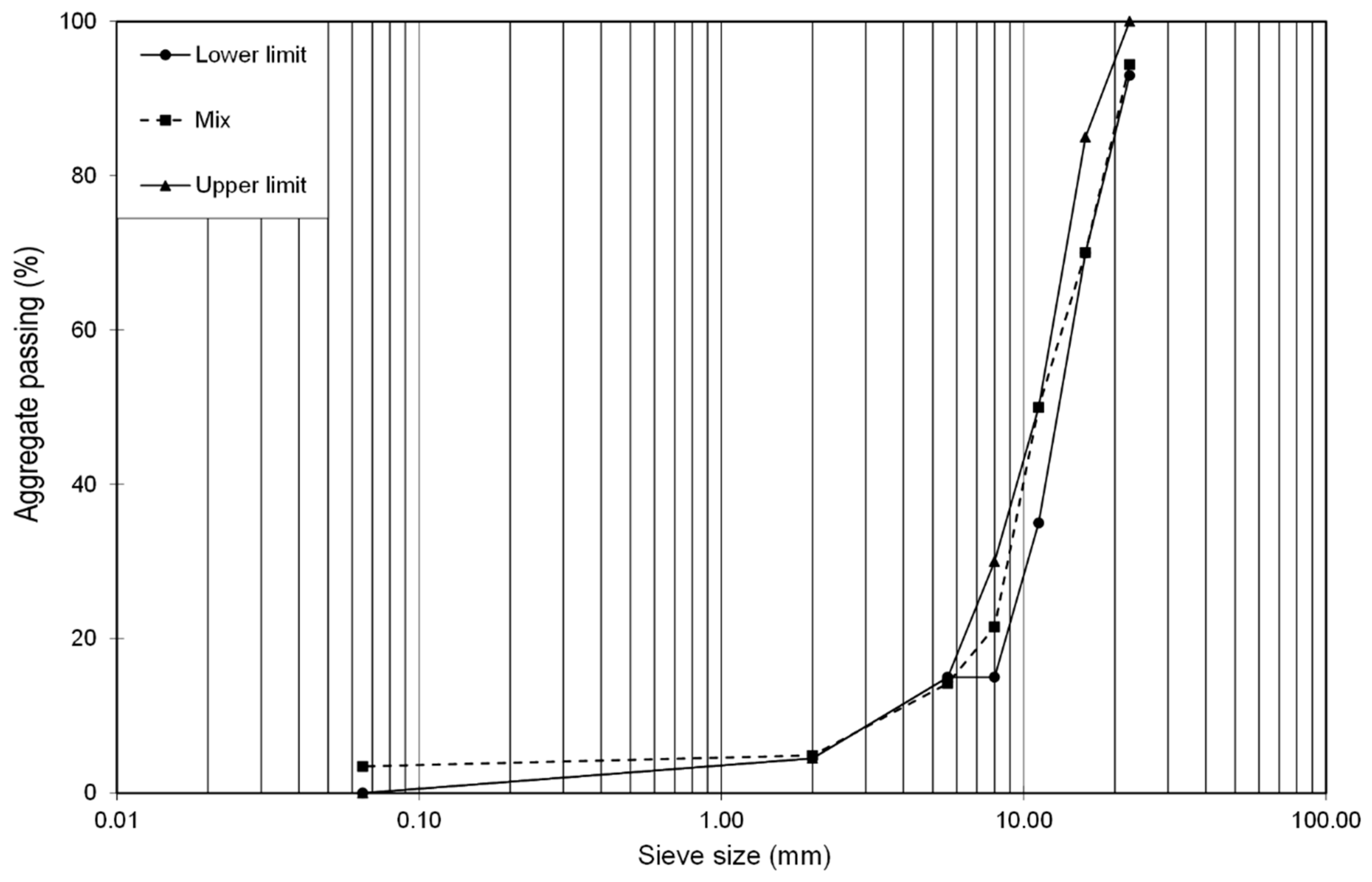
Figure 1 illustrates the mix grading curve and illustrates how the mix compares well with the grading envelope. The figure also shows the slightly higher passing of fine material than was required by the grading limits, but because of the high dust content of the aggregate, it was impossible to achieve a 100% match. Further consultations with industrial partners confirmed that the fit employed in this study compared favourably with PA mix production.
Table 1 summarises these mix constituents and shows their proportions in the mix, both with and without fibres. The fibres were added in an amount of 5%, which in the total mix volume represents 0.23%. Tabakovic et al. [
15] demonstrated that 5% is an optimum fibre content within an asphalt mix; mixes with a higher fibre content (10%) experience lower stiffness and strength values and have a lower healing efficiency. The aggregate mix constituent content was unchanged with the addition of fibres into the mix because the fibre is an active replacement for the bitumen and is not load carrying. Therefore, the fibre was inserted as a binder replacement.
The porous asphalt mix was prepared using a 5l Hobart mixer. Prior to mixing, all mix constituents were preheated to 160 °C for 2 h. During the mixing process, sand, filler, and bitumen were mixed first, and fibres were then added gradually to the mix to avoid a conglomeration of fibres within the mix. The addition of the fibres resulted in a prolonged mixing period, which caused the mix to cool down and reduced its workability. Therefore, the mix had to be reheated to 160 °C several times during the mixing process. The final mixing was performed by hand, to ensure that the mix constituents (sand, filler, and fibres) were fully and evenly coated in bitumen.
In order to account for the asphalt ageing, an aging programme was developed. The recommended by Kliewer et al. [
21], as follows: Long term; 15 years field ageing 4 h at 135 °C followed by 4 days at 85 °C in a forced air draft oven.
Recently, Tabaković et al. [
12] and Casado Barrasa et al. [
14] successfully used similar protocols to investigate the effect of short and long term aging of the asphalt mix containing alginate capsules and microcapsules encapsulating asphalt binder rejuvenator.
Following the asphalt aging procedure, the mix was preheated to the standard asphalt mixing/compaction temperature of 160 °C and the fibres were gradually added to the mix to avoid conglomeration of the fibres within the mix. After the fibres were included in the mix, the test specimens were prepared. The air void content in the mix design was 20%, with a target density of 2.05124 kg/cm3 for the control mix and 2.05088 kg/cm3 for the mix containing the fibres.
2.3. Test Specimen Compaction Procedures
2.3.1. SCB and ITS Test Specimens
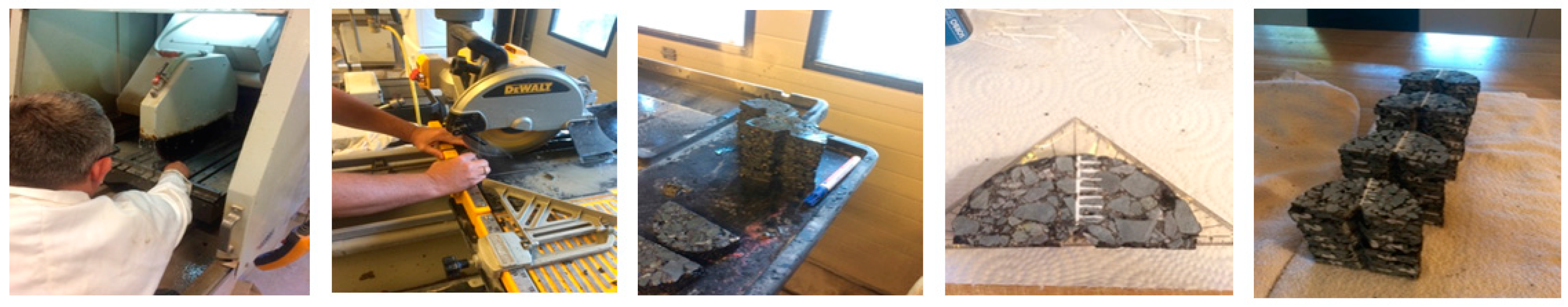
The SCB test was adopted for this study because its simple test specimen production process and test set up make it more advantageous in comparison to the standard 3PB test, where specimens are produced from a large test slab, making it a more expensive test process in terms of the materials required for test specimen production. The cylindrical test specimens were compacted in accordance with IS EN 12697-31:2007 using a SERVOPAC gyratory compactor. The static compaction pressure was set at 0.6 MPa with an angular velocity of 30 gyrations per minute and the gyratory angle was set at 1.25°. A set number of gyrations is used as the compaction control target; in this case, 100 gyrations. The specimens were compacted at dimensions of 100 mm in diameter and 100 mm in height. In total, five 100 × 100 mm cylindrical specimens were produced per mix. Following compaction, the test specimens were left in the moulds to cure for 2 h, at which point the SCB test specimens were machined using a masonry cutting saw.
Figure 2 shows the test specimen machining process, from which 12 SCB test specimens were produced per mix.
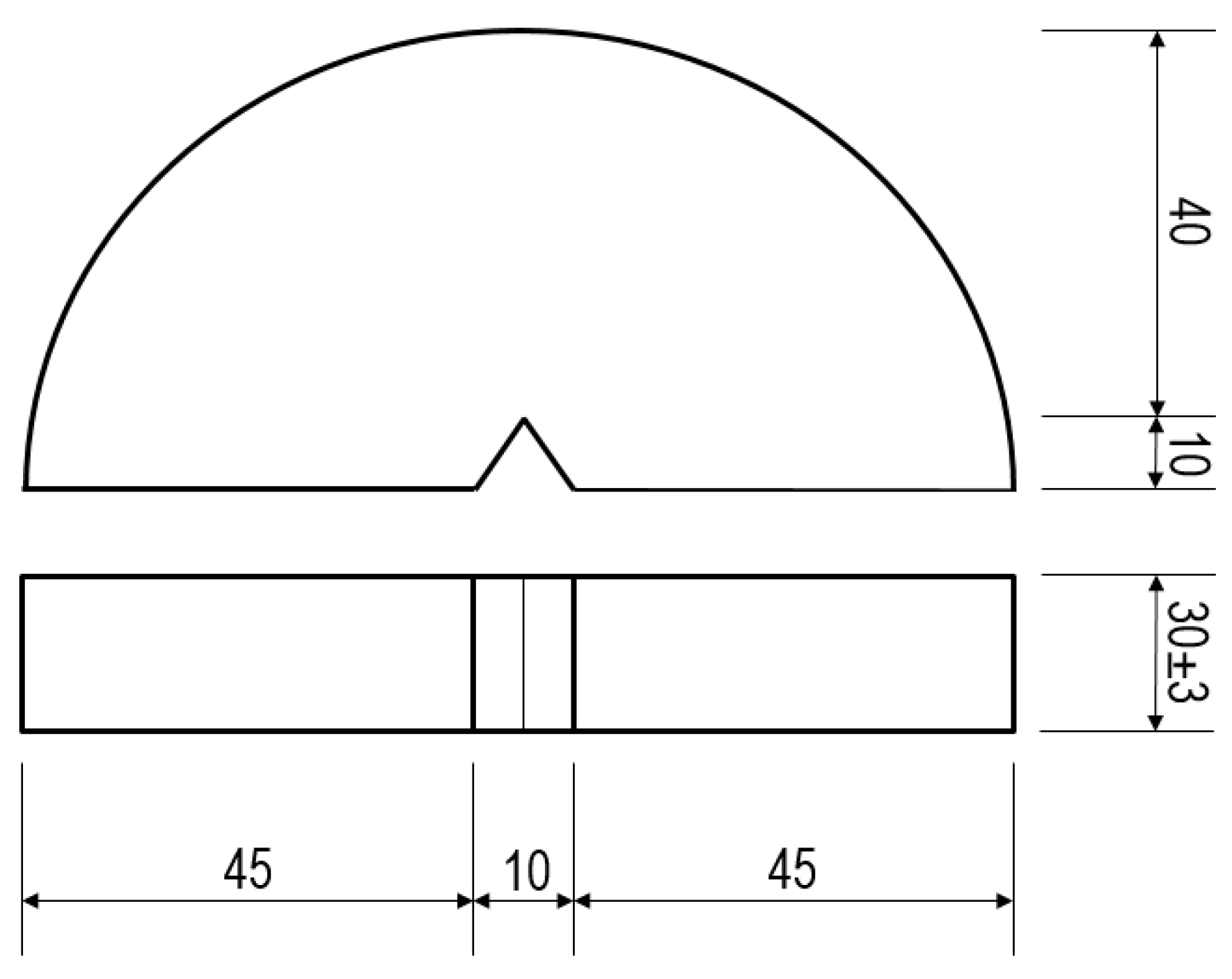
Figure 3 illustrates the geometry of the SCB test specimen.
The cutting was carried out in three steps (as illustrated in
Figure 2):
The samples are cut over the height in three equal parts of 30 ± 3 mm, using a 3 mm sawing blade.
These parts are cut across the diameter to obtain semi-circular specimens. The thickness of the specimen was adjusted to 20 ± 2 mm for crack propagation purposes (it creates a better crack visibility and speeds up the healing process). A 2 mm thick sawing blade was used for more precise cutting and excess material was discarded.
A triangular shaped notch of 10 ± 2 mm in length and 10 ± 2 mm in height was created at the base of the specimen. The same sawing blade was used as described in step 2.
Figure 3 shows a schematic diagram of an SCB test specimen.
For the production of the ITS test specimen, the same compacted asphalt cylinders were used as for production of the SCB test specimens, as described above. Following the curing process, a thin cylinder test was machined from each compaction cylinder, producing a total of six ITS test specimens.
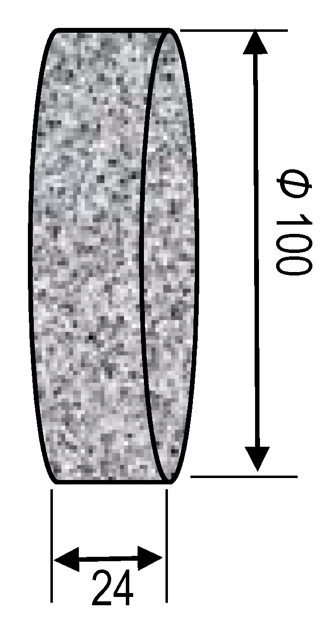
Figure 4 shows a schematic illustration of the ITS test specimen.
2.3.2. Fatigue Beam Test Specimens
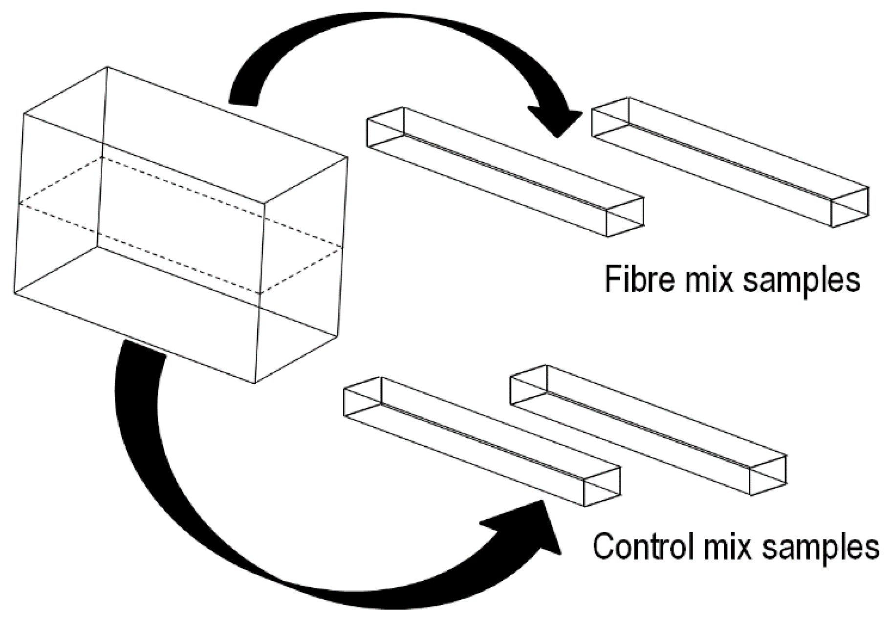
The fatigue test beams were machined form an asphalt slab which was produced by using a shear box compactor. The slab produced using the shear box compactor was of a length, width, and max height of 450 mm, 150 mm, and 180 mm, respectively. Due to the size of the slab and the large number of fibres required for its production, it was decided to produce a slab containing both mixtures, with and without fibres. The base of the slab did not contain fibres (control mix) and the top of the slab contained fibres. Four beams of 450 × 50 × 50 mm for 4PBT were cut out of the slab: two with and two without fibres.
Figure 5 illustrates the beam test specimen extractions from the compacted asphalt slab.
2.4. Testing
2.4.1. ITS Test
The Instron hydraulic test system was adjusted in order to perform an ITS test in accordance with EN 12697-23:2003. The ITS test was conducted by applying a vertical compressive strip load at a constant loading rate, in this case 0.1 mm/s, to a cylindrical specimen. The load was distributed over the thickness of the specimen through two loading strips at the top and base of the test specimen. The tests were conducted at a room temperature of 20 ± 2 °C. The aim of this study was to observe the crack healing efficiency (crack repair) and strength recovery of the asphalt mix with and without a self healing system. For this purpose, two ITS specimens were machined to a thickness of 24 mm (thin specimens) and one to a thickness of 33 mm (thick specimen). The standard EN 12697-23 indicates that the test specimens should not be thinner than 29 mm, but it was difficult to observe crack propagation though the full specimen thickness. Therefore, two specimens were machined to a 24 mm thickness so that crack propagation though the thickness of the test specimen could be observed, in addition to its subsequent healing, i.e., crack closure.
2.4.2. SCB Test
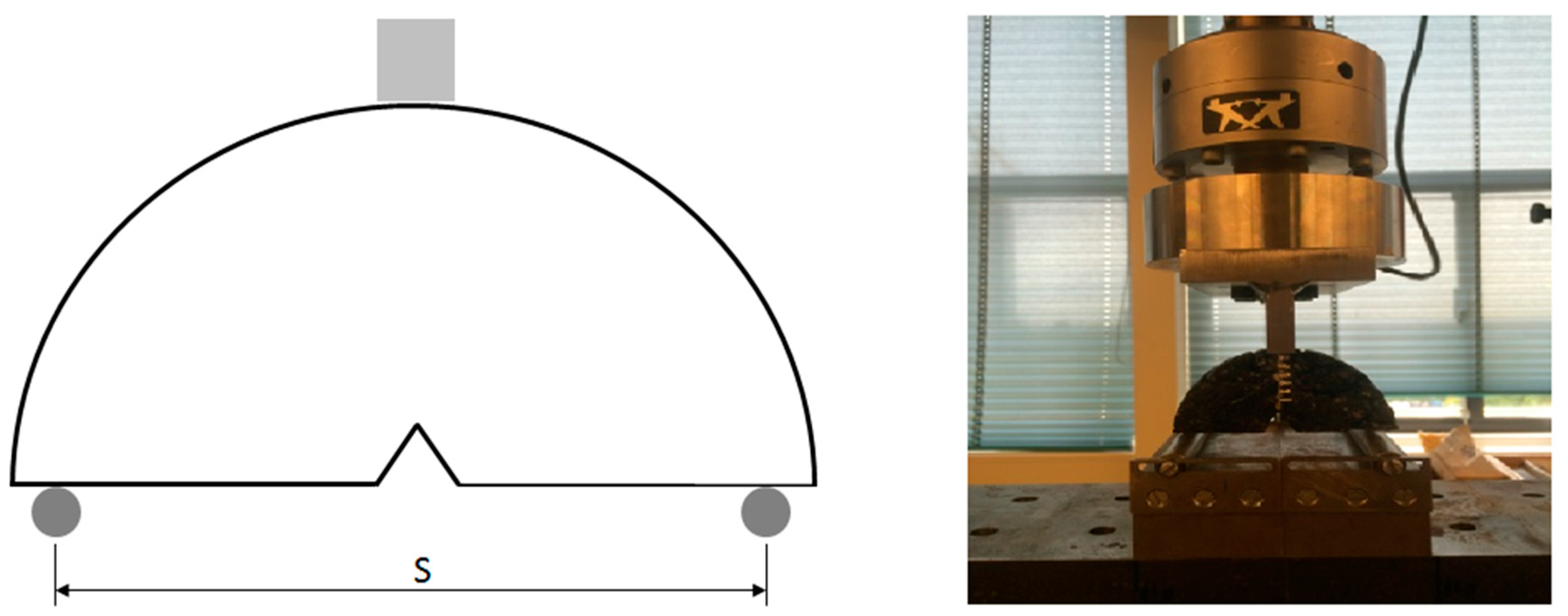
For the SCB test, a modified NCHRP09-46 procedure was adopted. The load was applied at the centre line, above the ‘V’ notch, at a loading rate of 0.1 mm/s and at a temperature of 20 ± 2 °C. The support span ‘S’ = 80 mm, included 80% of the spec diameter, leaving 10 mm on each side.
Figure 6 shows a schematic diagram and an actual view of the SCB test-setup. Several modifications to the test were made in the specimen geometry. The diameter of the specimen was reduced from 150 mm to 100 mm and the thickness from 50 mm to 20 mm, whereas the notch shape was changed from a straight line to the V-notch shape. These changes were employed in order to achieve full depth crack propagation throughout the depth of the test specimen, with the onset at the tip of the notch. Test samples were loaded until the crack has propagated to 25 mm or when the samples started to deform considerably. The crack propagation was measured in order to calculate the crack propagation speed. The crack propagation velocity was measured manually, by observing the crack propagation during the test, from the tip of the crack (0 mm) to the max (25 mm). For this procedure, a measuring scale was painted along the centerline of the specimen. The progression of the crack propagation was measured against the load and crosshead displacement.
In order to obtain rough estimations, the fracture energy (
GIc) and fracture toughness (
KIc) were calculated by following the NCHRP09-46 (for straight line notch), and using Equations (1) and (4), respectively:
where:
GIc = Fracture Energy (J/m2),
Wf = Work of the fracture–area under the load displacement curve (J),
P = Applied load (N),
u = load line displacement (m),
r = Specimen radius (m),
t = Specimen thickness (m),
a = Notch length (m).
It has to be noted that modifications of these formula to account for V-notch effects (instead of a straight notch) were not within the scope of this study. Instead, rough estimations were used to qualitatively investigate the effects that certain parameters and conditions had on the healing efficiency. Stiffness was measured from the elastic region of the curve slope.
2.4.3. 4PB Fatigue Test
The 4PB Fatigue test was employed as a third standard test for the evaluation of asphalt mix healing and asphalt healing system efficiency. The system does not allow for adequate crack propagation and monitoring as with the previous two test systems (ITS & SCB), but it is considered the most reliable means of evaluating asphalt pavement performance [
21]. The authors believe that the healing system for an asphalt pavement is only effective for micro cracks, because large cracks, even if closed, will still deform the test specimen, thus rendering it useless and challenging the results. Hartman et al. [
21] found that microcracks result in the creation of large cracks, leading to full pavement failure. Thus, a focus of the self healing system should be the prevention of large cracks and a test system able to insert fatigue loading, simulating repetitive wheel loading, with a deflection strain control allowing small deformations and small crack formation in the test specimen is most suitable for studying the asphalt mix healing and asphalt healing system efficiency.
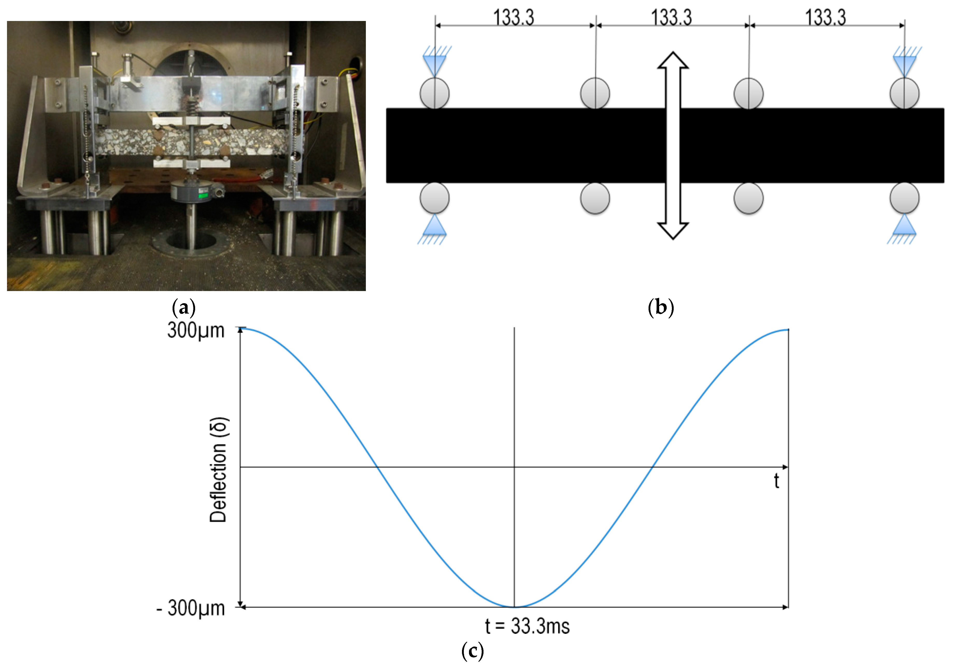
Figure 7a,b illustrate the 4PB Fatigue test set-up. They show a prismatic beam, 50 × 50 × 400 mm, subjected to four point bending with supposedly free rotation and translation at all load and reaction points. The bending is realised by a sinusoidal movement of the centre bearings in a vertical direction. The vertical position of the end-bearings is fixed. The applied displacement was generated by means of a servo-hydraulic testing device and an Instron Labtronic 8400 controller, which used feedback control of the actuator and an NI DAQ system with LABVIEW software to control the loading process and to collect test data. The program enables full control of the test system. A displacement transducer for the measurement of the deflection, not shown in
Figure 7b, is positioned at the middle of the upper surface of the test specimen, where the deflection is at a maximum (300 µm). The measuring range of the displacement transducer was ±1 mm, and its resolution, according to the specifications, was 1 µm. The measuring range of the load cell for the measurement of the force was 2 kN. The maximum deflection amplitude was 300 µm. The test temperature was 20 °C, and the frequency was fixed at 30 Hz.
Figure 7c shows the continuous sine-shaped deformation in the four-point bending test when the load frequency was 30 Hz and the deflection was 300 µm.
Since the load and displacement are continuously measured during the test, the parameters, such as flexural stiffness (
Smix), can easily be calculated. By shifting the stiffness versus loading frequency curves at a reference temperature using the Arrhenius equation [
22], a master curve for the stiffness can be determined (Equation (7)).
where:
Smix = stiffness,
fref = reduced frequency (Hz) and
a0, a1, a2 = material parameters.
The fatigue life is defined as the number of cycles where the stiffness is half of the initial value. Fatigue relationships are described using Equation (8).
where:
Nf = number of constant strain applications until the specimen reaches half of the initial stiffness,
ε = applied strain (µm/m) and
c & k = material parameters.
2.5. Asphalt Mix Healing Programme
In order to investigate effect of the fibres on the mechanical properties of the asphalt mix and evaluate the healing efficiency of the compartmented fibres encapsulating the rejuvenator, a special testing programme was designed, including:
two mixtures: control mix and mix containing fibres (5%),
following test methods: ITS, SCB, and 4PB Fatigue,
test temperature of 20 ± 3 °C,
healing temperature of 20 ± 3 °C,
healing time of 20 h and 40 h after the initial test.
For the 4PB Fatigue test, only a single healing stage was performed.
A parallel testing programme was conducted on samples with and without the healing system, where the mixture without the healing system was used as a reference guide. In this way, one can investigate whether the mix design is suitable for standard testing; for example, it is well-known, via international standards, what the expected stiffness performance of a particular standard mix is. Three tests were used in the investigation, namely, ITS, SCB, and 4PB Fatigue test methods.
The purpose of the ITS test was to evaluate the crack healing efficiency and strength recovery through experimental load-displacement histories. More specifically, the maximum load for all tests was determined and compared. In terms of the SCB tests, two parameters for both mixtures were monitored and compared: the crack speed and fracture toughness. Finally, the healing efficiency was also investigated using 4PB Fatigue tests via flexural strength vs. number of cycles histories. For all test methods, special attention was given to the repeatability of the results.
3. Results
3.1. ITS Test
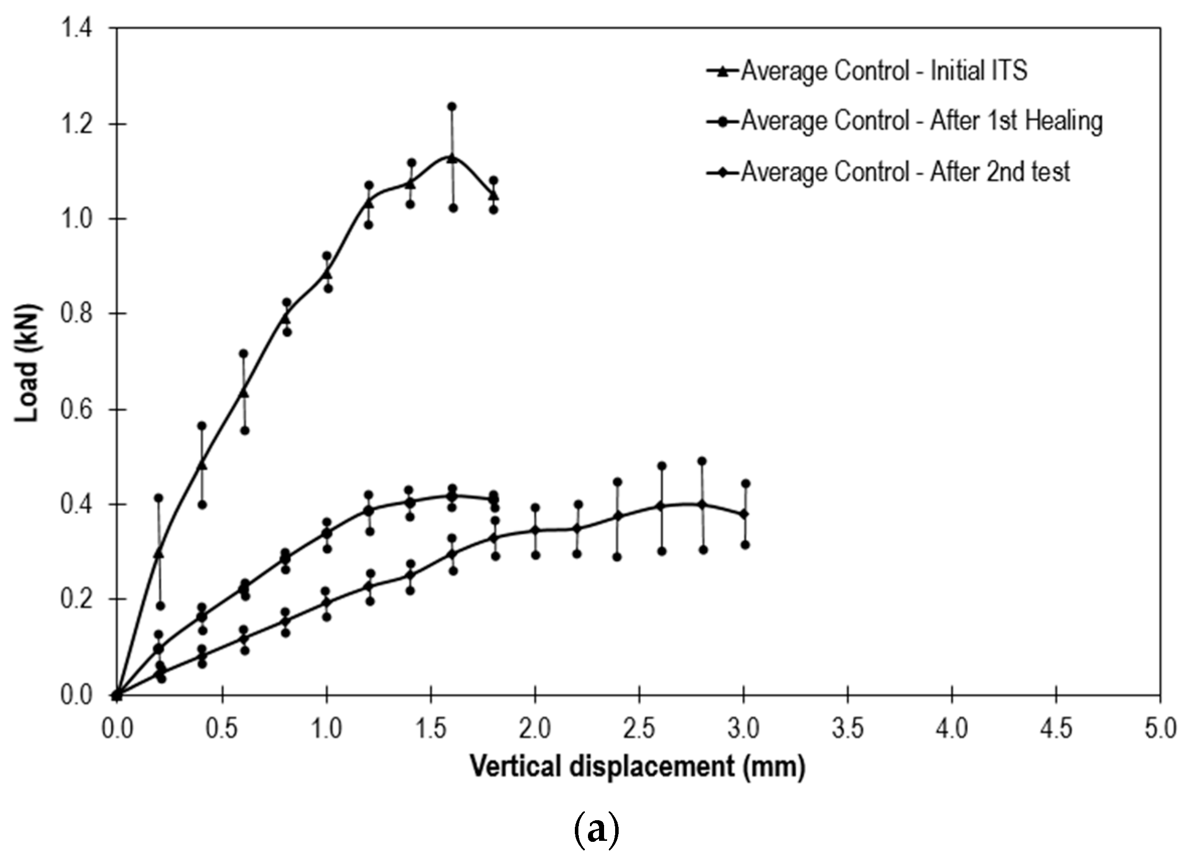
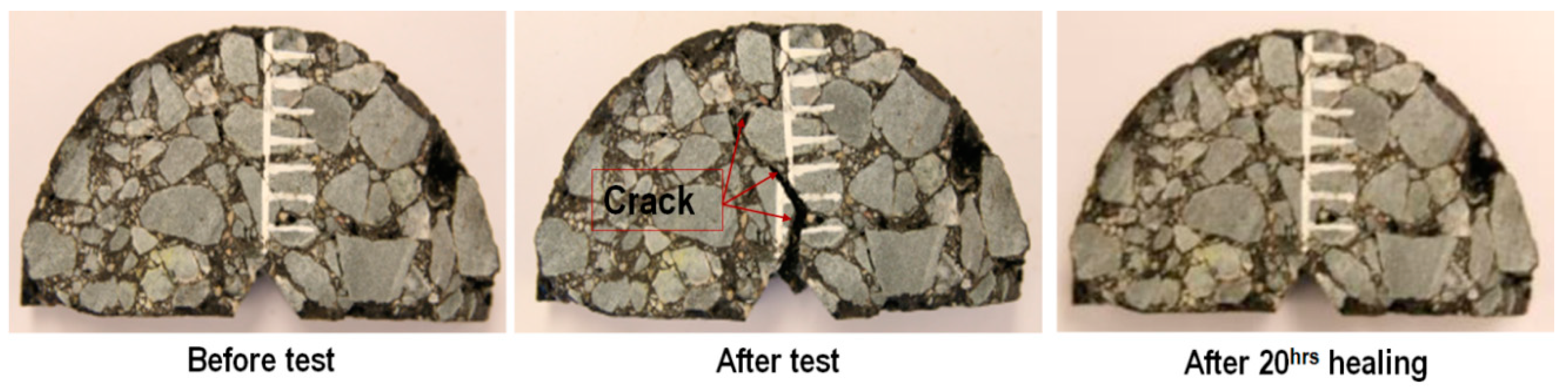
Figure 8 shows the results from the ITS test. It can be seen that the mix containing fibres (5%) underperformed in comparison to the control mix.
Figure 8b shows that the fibre mix has a higher variation in test results in comparison to the control mix (
Figure 8a). This could be caused by random fibre distribution throughout the compacted test specimen and also the possibility that rejuvenator was released from the fibre compartments during the mixing, compaction, and test specimen cutting procedure. Furthermore, the results presented in
Figure 8c illustrate that the asphalt fibre mix had a higher strength recovery after the first healing stage, by recovering 59% of its initial strength, whereas the control mix recovered only 36% of its original strength. It also outperforms the control mix where fibre ITS = 0.10 MPa and control mix ITS = 0.08 MPa. However, after the second healing stage, the control mix outperforms the fibre mix. Nevertheless, a mix losing 64% and 70% of its initial strength would be considered as one that had failed.
3.2. SCB Test
The SCB test was specifically employed in order to study crack propagation and its closure (healing) in an asphalt mix.
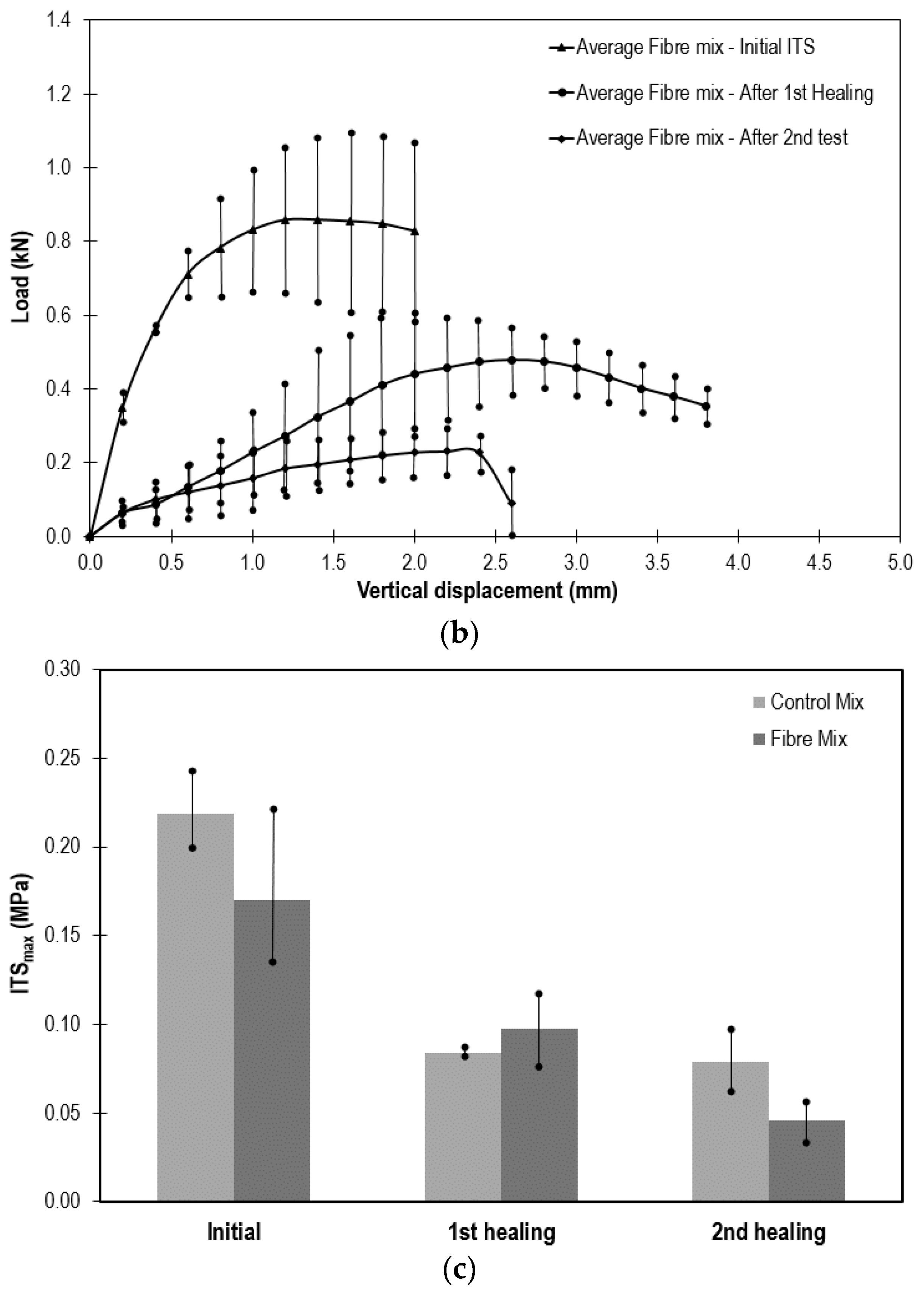
Figure 9 illustrates successful crack closure (healing) in an asphalt test specimen containing 5% compartmented alginate fibres encapsulating the rejuvenator after 20 h of healing.
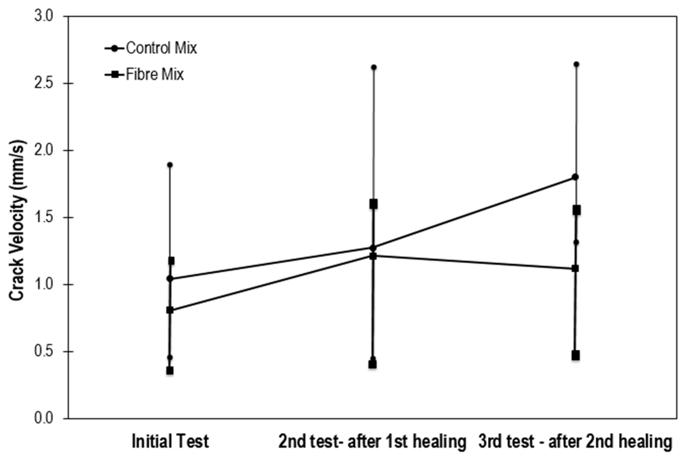
3.2.1. Crack Speed
Figure 10 shows the crack propagation speed within the test sample at the initial test and after two healing stages. It is clear from the graph that the fibre mix experiences slower crack propagation. This could be due to the softened binder and reduced fracture energy available for crack propagation. This result illustrates the benefits of the compartmented fibre encapsulating a rejuvenator mix in terms of crack propagation, where the rejuvenation (softening) of aged binder can reduce the brittleness of the aged binder, thereby reducing the energy available for crack propagation.
3.2.2. Fracture Toughness (KIc) and Fracture Energy (GIc)
Table 2 and
Table 3 summarise the fracture energy and fracture toughness results. The results confirm that the asphalt mix containing fibre has a lower fracture toughness and energy, and thus a reduced crack velocity (
Figure 10) in comparison to the control asphalt mix. However, a detailed statistical analysis of these results shows significant variation between tests. The coefficient of variation ranges from 25% at the initial test to 97% at the second test after 20 h of healing for the control mix and from 27% to 74% for the fibre mix under the same conditions. Therefore, it is questionable whether this test can be used to adequately analyse the healing efficiency of the asphalt mixtures.
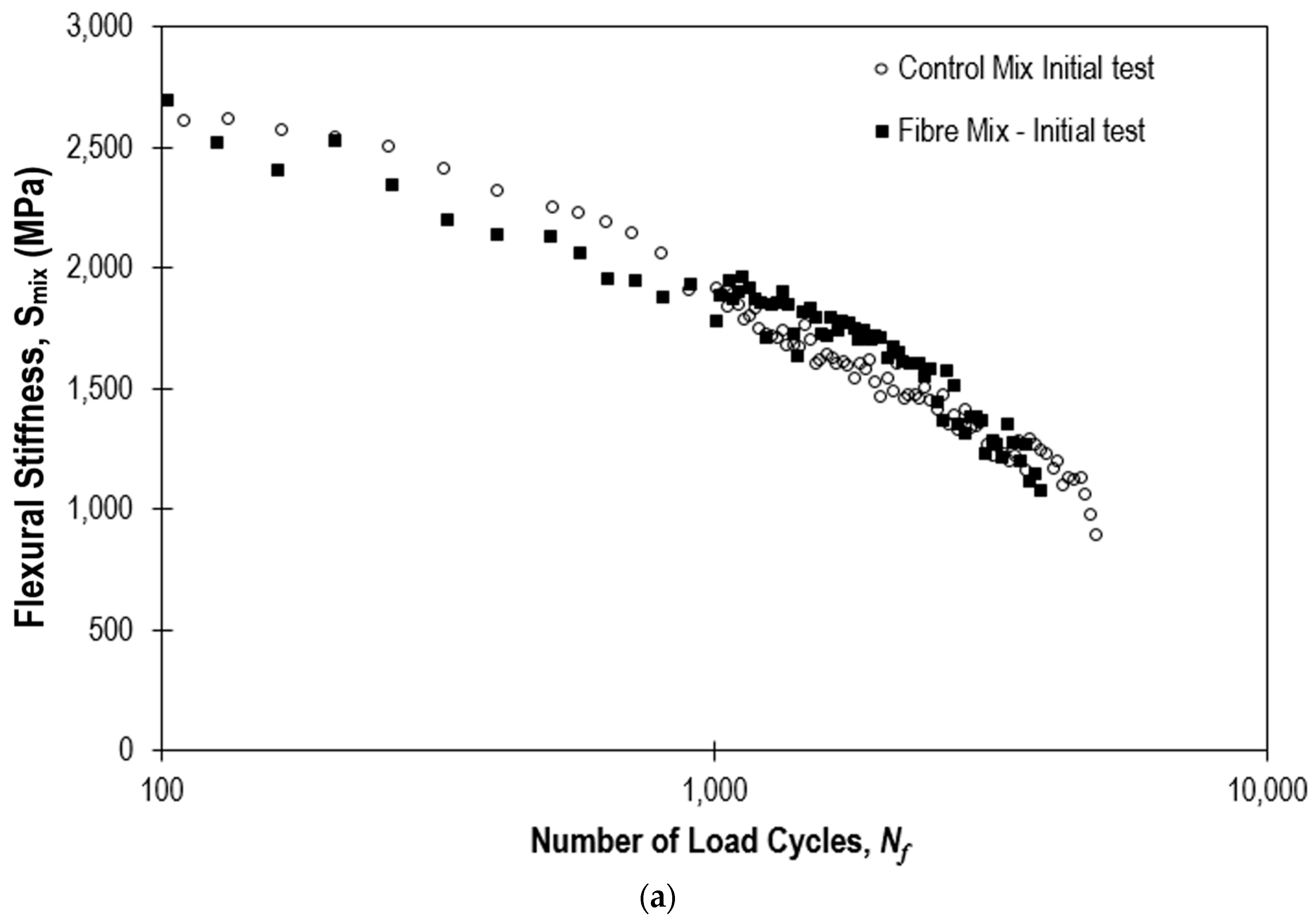
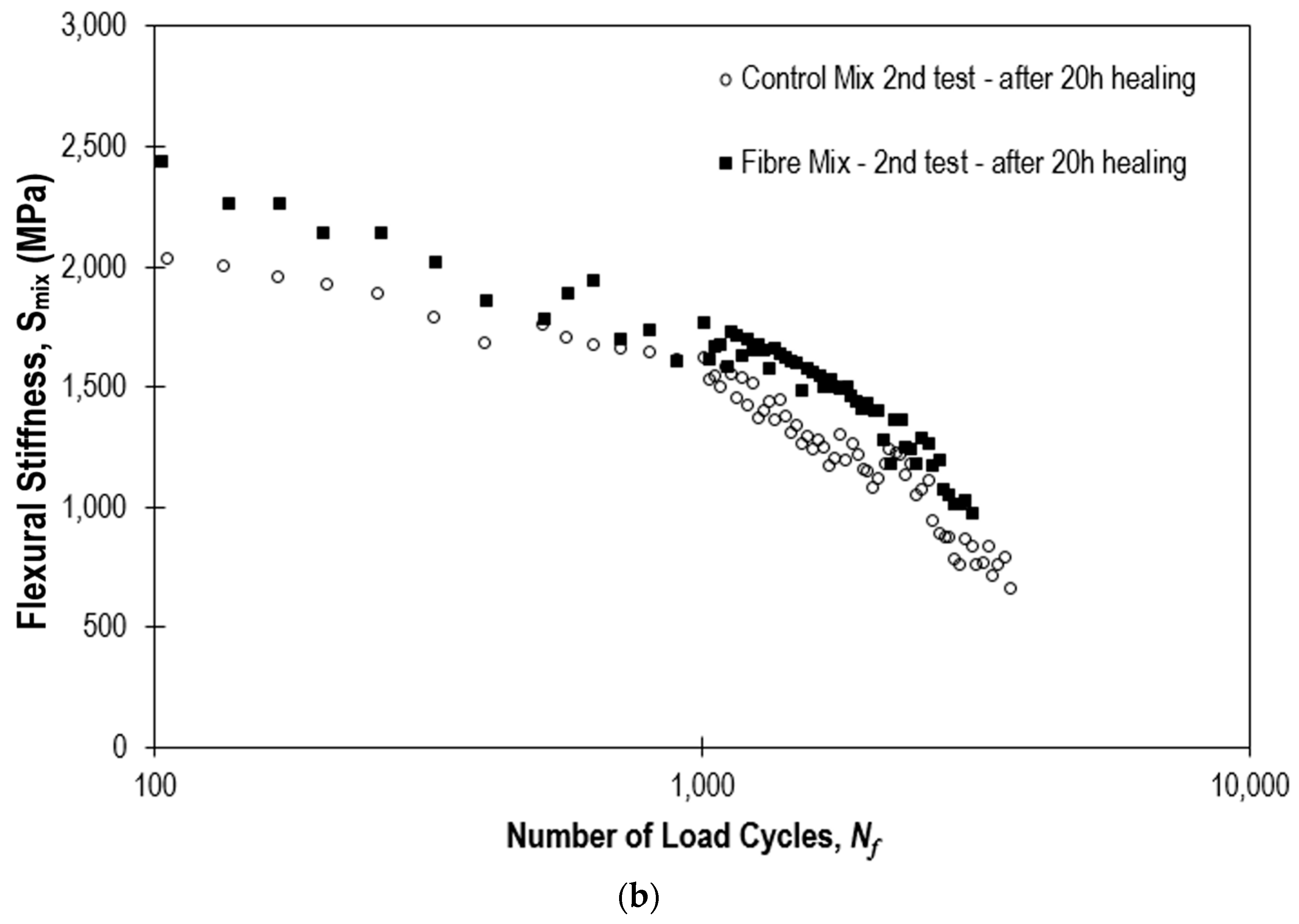
3.3. 4PB Test-Healing Efficiency
Figure 11 shows the healing efficiency of the PA control mix and fibre mix flexural stiffness (
Smix). The results show a very close initial test performance (
Figure 11a). However,
Figure 11b shows a higher stiffness recovery for the PA fibre mix after 20 h healing at 20 °C. These results demonstrate the potential benefits of the PA mix containing compartmented alginate fibres encapsulating the rejuvenator.
4. Discussion & Conclusions
The healing capacity of the compartmented alginate fibres encapsulating a rejuvenator as a self healing system for Porous Asphalt (PA) mix was evaluated in this study, by comparing the performance of asphalt mixtures with and without healing systems. By carrying out the parallel tests programme, the control mixture (without a healing system) can be used to ascertain whether the self healing asphalt mix design is suitable for standard testing. The test results can be compared to the historical data sets of standard asphalt mixtures. The results further demonstrated the value of such comparisons, as in some cases, mixtures without the healing system outperformed mixtures with the healing system. This approach gives researchers the opportunity to further investigate and correct self healing system design or asphalt pavement mix design.
The healing time adopted in this study was 20 h at 20 °C, and this healing time was shown to be sufficient for this particular healing system, which employs a rejuvenator as the healing agent. However, the healing time can be reduced and the temperatures increased, but if the temperature is decreased, the healing time needs to be increased. This is due to the time that it takes for the rejuvenator to diffuse into the aged binder.
The key aim of this study was to assess test methods for the evaluation of the asphalt healing performance. Specifically, the ITS, SCB, and 4PB test methods were used to evaluate the healing performance of asphalt mixtures containing compartmented fibres as a self healing system. The results from the ITS and SCB tests showed that the initial strength of the control mix is higher than that of the mixtures containing fibres. This was an unexpected result as research had previously suggested that fibres can reinforce and strengthen asphalt mixtures [
14,
15]. It is believed that the reduction in the material initial strength was caused by the test specimen machining process; during the test specimen production process, fibre compartments were damaged, which caused the release of the rejuvenator and the premature triggering of the healing process, i.e., rejuvenation. In addition, the results from the SCB test showed that the crack propagation speed for asphalt mixtures containing fibres is lower than that for the control asphalt mix. This is due to aged binder rejuvenation, binder softening, caused by the release of the rejuvenator into the asphalt mix. In general, the observations from the ITS and SCB tests demonstrated that full loading-full failure causes large deformations of the test specimens, significantly deforming the shape of the test specimen. These deformations are difficult to repair, thus making test specimens unusable for repeated tests after healing and these tests unsuitable for an evaluation of the asphalt healing.
On the other hand, the 4PB Fatigue test, as it is strain controlled (deflection controlled), controls the damage to the test specimen and the minor damage caused presents as micro cracks, which are common on-site. Therefore, the most suitable and convenient test method for the evaluation of the self-healing asphalt mix performance is the 4PB Fatigue test method. The results from these tests showed that the compartmented alginate fibres encapsulating a rejuvenator have a better stiffness recovering ability in comparison to the control asphalt mix (without fibres). These results confirm the potential of the compartmented alginate fibres encapsulating a rejuvenator as an asphalt healing system. However, the development of the healing system is still in its infancy and requires further development, such as: modifying the fibre composition in order to improve its mechanical and the thermal strength of the fibres. The improvement of the compartmented alginate fibres mechanical and thermal properties will be the focus of future research studies.
Acknowledgments
The authors wish to thank: Bert Jan Lommerts and Irina Catiugă, Latexfalt, B.V. for the support they provided to this project. The Authors would also like to thank Santiago Garzia from the Novel Aerospace Materials group, Faculty of Aerospace Engineering, Delft University of Technology, for organising the use of the fibre spining machine. This research was conducted under the Marie Curie IEF research funding, research project Self-healing Asphalt for Road Pavements (SHARP), project number 622863.
Author Contributions
Amir Tabaković, is a lead researcher on the project (Self Healing Asphalt Pavements; SHARP). Tabaković was responsible for every aspect of this work, this includes: work design, fibre production, material mix design, material mixing, compaction, carrying out experimental work (all: ITS, SMB and 4PB test), data collection and analysis and manuscript writing, coordinating submission and contact with the journal. Luke Schuyffel, was researcher on the project. As part of his final year project he has carried out the ITS and SCB test. His work included: fibre production, asphalt mix production, test specimen preparation (compaction and cutting), carrying out the experimental testing ITS and SCB test analysis. Aleksandar Karač, assisted in fracture (SCB) testing design and test results analysis. He was also involved in manuscript resubmission writing and modification during the review process. Erik Schlangen, is PI of the project (Self Healing Asphalt for Road Pavements—SHARP). He was involved from the outset in the project design, fibre and mix design, testing, test data analysis, manuscript writing and in preparation of the responses to the reviewers comments.
Conflicts of Interest
The authors declare no conflict of interest. This research was conducted under the EC FP7 Marie Curie IEF research funding, research project Self-healing Asphalt for Road Pavements (SHARP), project number 622863. The founding sponsors had no role in the design of the study; in the collection, analyses, or interpretation of data; in the writing of the manuscript, and in the decision to publish the results.
References
- Tabaković, A.; Schlangen, E. Self-Healing Technology for Asphalt Pavements. In Self-Healing Materials; Hager, M.D., van der Zwaag, S., Schubert, U.S., Eds.; Springer International Publishing: Cham, Switzerland, 2016; pp. 285–306. [Google Scholar]
- Fisher, H. Self repairing materials—Dream or reality. Nat. Sci. 2010, 2, 873–901. [Google Scholar] [CrossRef]
- García, A.; Schlangen, E.; Van de Ven, M.; Liu, Q. A simple model to define induction heating in asphalt mastic. Constr. Build. Mater. 2012, 31, 38–46. [Google Scholar] [CrossRef]
- García, A.; Schlangen, E.; van de Ven, M.; Liu, Q. Electrical conductivity of asphalt mortar containing conductive fibers and fillers. Constr. Build. Mater. 2009, 21, 3175–3181. [Google Scholar]
- García, Á.; Schlangen, E.; van de Ven, M. Two ways of closing cracks on asphalt concrete pavements: Microcapsules and Induction Heating. Key Eng. Mater. 2010, 417–418, 573–576. [Google Scholar] [CrossRef]
- García, A.; Schlangen, E.; van de Ven, M. Induction heating of mastic containing conductive fibers and fillers. Mater. Struct. 2011, 44, 499–508. [Google Scholar] [CrossRef]
- Su, J.F.; Schlangen, E. Synthesis and physicochemical properties of high compact microcapsules containing rejuvenator applied in asphalt. Chem. Eng. J. 2012, 198–199, 289–300. [Google Scholar] [CrossRef]
- Su, J.F.; Qiu, J.; Schlangen, E. Stability investigation of self-healing microcapsules containing rejuvenator for bitumen. Polym. Degrad. Stab. 2013, 98, 1205–1212. [Google Scholar] [CrossRef]
- Su, J.F.; Qiu, J.; Schlangen, E.; Wang, Y. Investigation the possibility of a new approach of using microcapsules containing waste cooking oil; in-situ rejuvenation. Constr. Build. Mater. 2015, 74, 83–92. [Google Scholar] [CrossRef]
- Su, J.F.; Qiu, J.; Schlangen, E.; Wang, Y. Experimental investigation of self healing behaviour of bitumen/microcapsule composites by modified beam on elastic foundation method. Mater. Struct. 2015, 48, 4067–4079. [Google Scholar] [CrossRef]
- Tabaković, A.; Post, W.; Garcia, S.J.; Schlangen, E. Use of compartmented Sodium-Alginate fibres as healing agent delivery system for asphalt pavements. Proceedings of European Materials Research Society Fall Meeting, Warsaw, Poland, 15 September 2015. [Google Scholar]
- Tabaković, A.; Post, W.; Cantero, D.; Copuroglu, O.; Garcia, S.J.; Schlangen, E. The reinforcement and healing of asphalt mastic mixtures by rejuvenator encapsulation in alginate compartmented fibres. Smart Mater. Struct. 2016, 25, 084003. [Google Scholar] [CrossRef]
- Garcia, A.; Jelfs, J.; Austin, C.J. Internal asphalt mixture rejuvenation using capsules. Constr. Build. Mater. 2015, 101 Pt 1, 309–316. [Google Scholar] [CrossRef]
- Barrasa, R.C.; López, V.B.; Montoliu, C.M.P.; Ibáñez, V.C.; Pedrajas, J.; Santarén, J. Addressing durability of asphalt concrete by self-healing mechanism. Procedia Soc. Behav. Sci. 2014, 162, 188–197. [Google Scholar] [CrossRef]
- Tabaković, A.; Braak, D.; van Gerwen, M.; Copuroglu, O.; Post, W.; Garcia, S.J.; Schlangen, E. The compartmented alginate fibres optimisation for bitumen rejuvenator encapsulation. J. Traffic Transp. Eng. 2017, in press. [Google Scholar]
- Prajer, M.; Wu, X.; Garcia, S.J.; van der Zwaag, S. Direct and indirect observation of multiple local healing events in successively loaded fibre reinforced polymer model composites using healing agent-filled compartmented fibres. Compos. Sci. Technol. 2015, 106, 127–133. [Google Scholar] [CrossRef]
- Mookhoek, S.D.; Fischer, H.R.; van der Zwaag, S. Alginate fibres containing discrete liquid filled vacuoles for controlled delivery of healing agents in fibre reinforced composites. Compos. A Appl. Sci. Manuf. 2012, 43, 2176–2182. [Google Scholar] [CrossRef]
- Kringos, N.; Khedoe, R.; Scarpas, A.; de Bondt, A. On the development of a new test methodology for moisture damage susceptibility of asphalt concrete. Proceeding of the 5th International Conference Bituminous Mixtures and Pavements, Thessaloniki, Greece, 1–3 June 2011; pp. 857–867. [Google Scholar]
- Tabaković, A.; Gibney, A.; McNally, C.; Gilchrist, M.D. The influence of recycled asphalt pavement on the fatigue performance of asphalt concrete base courses. J. Mater. Civ. Eng. 2010, 22, 643. [Google Scholar]
- Liu, Q. Induction Healing of Porous Asphalt Concrete. Ph.D. Thesis, Civil Engineering and Geosciences, TU Delft, The Netherlands, 2 October 2012. [Google Scholar]
- Hartman, A.M.; Gilchrist, M.D. Evaluation Four-Point bending Fatigue of Asphalt Mix Using Image Analysis. J. Mater. Civ. Eng. 2004, 16, 9. [Google Scholar] [CrossRef]
- Pramesti, F.P.; Molenaar, A.A.A.; Van de Ven, M.F.C. The Prediction of Fatigue Life based on Four Point Bending Test. Procedia Eng. 2013, 54, 851–862. [Google Scholar] [CrossRef]
© 2017 by the authors. Licensee MDPI, Basel, Switzerland. This article is an open access article distributed under the terms and conditions of the Creative Commons Attribution (CC BY) license (http://creativecommons.org/licenses/by/4.0/).


