Ambient Light Rejection Using a Novel Average Voltage Tracking in Visible Light Communication System


Department of Electronic Engineering, Pukyong National University, Nam-Gu, Busan 48513, Korea
*
Author to whom correspondence should be addressed.
Appl. Sci. 2017, 7(7), 670; https://doi.org/10.3390/app7070670
Submission received: 31 May 2017
/
Revised: 23 June 2017
/
Accepted: 26 June 2017
/
Published: 29 June 2017
(This article belongs to the Special Issue Selected Papers from IEEE ICASI 2017)
Abstract
:Featured Application
Robust error-free visible light communication receiver.
Abstract
The quality of a received signal is one of the most important factors to be considered when designing a receiver for visible light communication (VLC) systems. Therefore, it is necessary to evaluate the robustness of the VLC receiver circuit in low-signal-to-noise ratio (SNR) communication. The SNR is the quantity characterized by the ratio of the signal power to the noise power of the received signal. The noise generates an offset voltage and distorts the desired signal waveform. Thus, a low SNR makes it difficult to retrieve the data. Among the sources of noise, ambient light has the most negative impact on the VLC data signal. Therefore, the novel receiver proposed by us acts as an ambient light rejection circuit. As our average-voltage tracking circuit is insensitive to the sunlight and indoor fluorescent light, our design could be a solution to enhance the performance of low-SNR VLC systems. Several experiments are conducted using light of same intensity, but with different distances and semi-angles. Experimental results demonstrate that robust interference rejection is possible to send an error-free communication with an On-Off Keying modulation base on microcontroller up to 1 Mbps at an SNR of −2.7 dB.
1. Introduction
In recent years, visible light communication (VLC) has attracted a lot of interest as a novel technology in short-range wireless communication [1,2,3,4,5]. VLC is one of the free-space optics research fields that use visible light between 375 and 780 nm as the variant in data communication [6,7,8]. VLC is a particularly advantageous communication method, as it can offer a high data rate and is environmentally friendly, nonhazardous, reliable, and particularly secure because of line-of-sight propagation, which makes VLC a potential alternative to radio frequency (RF) technology for wireless communication.
Light-emitting diodes (LEDs) have been employed not only for lighting, but also utilized as transmitters in most VLC systems because of their high performance, energy efficient properties, low cost and fast response relative to the traditional incandescent and fluorescent lamps [9]. In addition, image sensors [10,11,12,13,14] or photodiodes (PDs) [15,16,17] are typically used as receivers. Our experiment was conducted using an LED-PD. With PD and complex modulation methods, such as quadrature amplitude modulation (QAM), orthogonal frequency-division multiplexing (OFDM) or a combination of QAM and OFDM, the speed in the VLC system was demonstrated to reach as high as a few tens of gigabits per second [18,19]. Nevertheless, the gigabit per second speed has only been conducted in laboratory environment with offline modulation and demodulation (signal processing with Matlab). For wider applications, we must consider VLC in real-time operating systems and variable signal-to-noise ratio (SNR) conditions.
On the PD-receiver side, there are three main sources of noise for indoor VLC systems, such as ambient noise, shot noise, and electrical pre-amplifier noise (thermal noise). The noises have a distortion effect on the received signal. The offset voltage is generated by noise and amplified along with the original signal in the data demodulating process. If the offset voltage is considerably large, amplifier saturation may occur because of the circuit limitations. Therefore, a low SNR is a challenge that must be overcome before implementing and deploying indoor VLC systems on a larger scale. Typically, in conventional methods, a high-pass filter (HPF) is adapted to block direct current (DC) voltage signals affected by noise [20,21]. However, contrary to RF, with the On-Off Keying (OOK) modulation, the signals received by a photo-detector are DC voltages as square waveforms; therefore, if we use an HPF, the phase and amplitude responses of the circuit change significantly and produce a signal known as a differentiator. In addition, transmissions are unstable at the beginning because of the relaxation time effect, which even causes data loss [22]. Therefore, for the OOK modulation with this method, in theory, it requires SNR = 13.6 dB for it to be error-free [9]. As Zixiong Wang et al. reported [20], an SNR of 5.4 dB was required to achieve a bit error rate (BER) of 5 × 10⁻⁴. With coding for the balance of 0 bits and 1 bits, a BER of 10−6 needs an SNR of 2.5 dB [3]. Thus, under the low-SNR condition, the HFP does not have a good performance.
With this motivation in mind, we proposed a novel VLC receiver design to solve the problem. More specifically, the average-voltage tracking (AVT) circuit is implemented at the receiving circuit to detect the average voltage value produced by noise and then to eliminate this voltage to demodulate the original data. In this paper, we will discuss the SNR analysis and the performance enhancement technique for the receiver at a low SNR.
The rest of this paper is organized as follows. In Section 2, the impact of light interference on the receiver and the impact of the HPF on the performance of the VLC systems are discussed, following which a novel receiver design is proposed. In Section 3, the experimental setup is presented along with the results, and the advantages of the receiver design are analyzed. Finally, conclusions are provided in Section 4.
2. SNR Analysis of the VLC System with Light Interference
2.1. Optical Wireless Channel
To integrate a built-in VLC system, we need to combine fluorescent lamps and LED to have sufficiently large power for both lighting and high-speed wireless personal area networks. In general, fluorescent lamps are located within a room, and its illumination is as wide as the lighting equipment. Thus, the experiment was conducted with an LED located at the room center under fluorescent lamps.
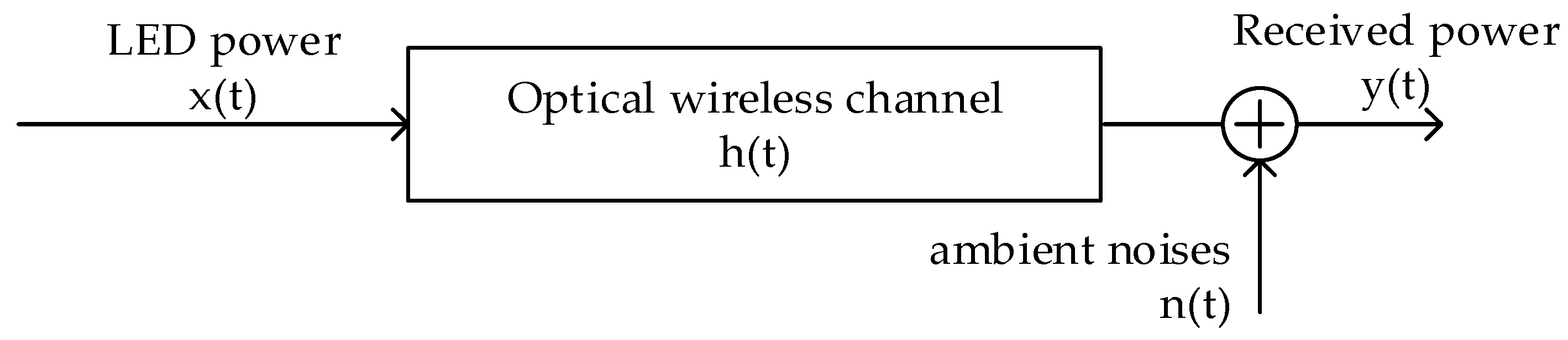
In this scenario, we assume that only fluorescent lamps contribute to the ambient noise. As shown in Figure 1, the optical channel can be modeled as a linear system [21]:
where the symbol denotes convolution, LED power is the input, received power is the output, and impulse response function describes the system dynamics.
The time-average transmitted LED power is given by [21]:
In this system, the LED is located at a high position, and the irradiance of the LED for communication is smaller than the size of the room. Thus, we do not consider intersymbol interference. The channel DC gain is given by [9]:
Fundamentally, the emitted light of the LED is according to a Lambertian emission pattern. Hence, considering only the line of sight transmission path, we have:
where is the order of Lambertian emission, is the transmitter semi angle, is the distance between the transmitter and the receiver, is the perceived area of the photo-detector, and is the angle of incidence.
The average received optical power is given by:
Thus, the SNR of the output signal follows from the formula:
As the ambient light comes exclusively from the fluorescent lamps based on our assumption, is considered as the light power of the fluorescent lamps. Basically, can be calculated in a manner similar to that of with different distances and other parameters. We suppose the arrangement of the lamp to be symmetrical, so depends only on the distance.
A glance at Equations (5) and (6) reveals that the SNR depends on the semi angle of lights, angle of incidence, and distance between the transmitter, noise sources, and the receiver. From Equation (7), we see that the variation in the semi angle affects the SNR more than the change in the distance, because is only a function of the distance and the increment of the distance makes increase. Considering the SNR variation is important for the mobility VLC analysis. The receiver response to the conditions could be used to evaluate the adaptive and robust performance of the systems.
2.2. Novel Receiver Design
In VLC systems, the following modulation techniques, namely OOK, pulse width modulation, variable pulse position modulation, and multiple pulse position modulation use DC signals with a rectangular waveform. For the demodulations of those methods, a fixed and stable signal is required. According to the Fourier series expansion method, a rectangular wave is the resultant of superposition of an infinite number of sinusoidal waves. Figure 2 shows the conventional receiver with a HPF. When we use the HPF at the receiver, low-frequency signals are removed. It causes the end of each half cycle of the square wave to drop or tilt back towards zero because of the phase shift in the harmonic components. Furthermore, the relaxation time effect leads to poor performance. Thus, it is necessary to design a novel circuit to solve these problems.
Figure 3 illustrates the principle of our novel receiver circuit design. It has six stages such as photodiode converting optical signals into electrical signals, a transimpedance amplifier (TIA), AVT for detecting the average value of the converted voltage signal, a voltage subtractor (VS) to remove the bias signal, a voltage amplifier (VA), and a voltage comparator (VC).
To detect the photodiode signal, voltage or current could be used. Current measurements have a better linearity, offset, and high-speed response. Thus, by using the TIA, we can convert the generated photocurrent into the voltage signal to process. There are two methods to design a TIA: photoconductive (PC) (reverse biased) and photovoltaic (unbiased) (PV). The PC mode reduces the response time because of an increase in the depletion region width and a consequent decrease in the junction capacitance. However, applying a reverse voltage makes the dark and noise currents increase. The PV mode uses zero bias and operates based on the photovoltaic effect, which is the basis for solar cells. The PV mode is suggested when a photodiode is utilized for low-frequency or ultralow-light intensity applications. The selection of the operation mode depends on the specific requirements of the application considered. In this work, we used the PC mode, because it could help to improve the bandwidth, and the high dark current is acceptable because of the ambient light conditions.
After the TIA stage, the raw signal received from the LED and other sources is amplified to around 1–2 V. The AVT stage is designed as an active low-pass filter with a 100 Hz frequency cutoff to obtain a 50–60 Hz signal and the harmonic frequency signals from the lamps and below 10 Hz from others (sunlight or light devices…). Through the VS stage, the raw signal subtracts the filtered signal to minimize the effect of noise. Then, only the signal received from the LED goes to the next stage. After these stages, the amplitude of the voltage signal ranges from −50 mV to 50 mV.
Before comparing with a reference voltage, the original data is amplified to the range from −1 to 1 V in order to avoid electrical circuit noise. Moreover, we adapt a hysteresis method to offer a high noise immunity and a stability comparator. The hysteresis comparator uses two different threshold voltages to prevent multiple output state transitions.
The OOK output signal from our receiver is demodulated in a microcontroller (STM32F4, STMicroelectronics, Geneva, Switzerland) to calculate the BER.
3. Experiment and Results
3.1. SNR Distribution Experiment
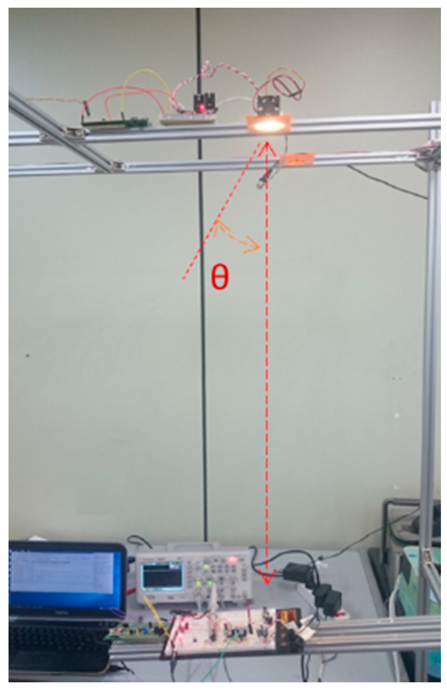
Several experiments were conducted with an LED at the center of the room, as shown in Figure 4. The parameters of the VLC experiments considered in this research are listed in Table 1.
In the experiment, we used Newport 1918 Power Meter (Newport Corporation, Irvine, CA, USA) to measure the average power of light (unit) every 50 s, repeating 10 times. We measured under three conditions, only LED transmitter, ambient light without the emitted light from the LED, and LED under interference. The SNR can be calculated using Equation (6).
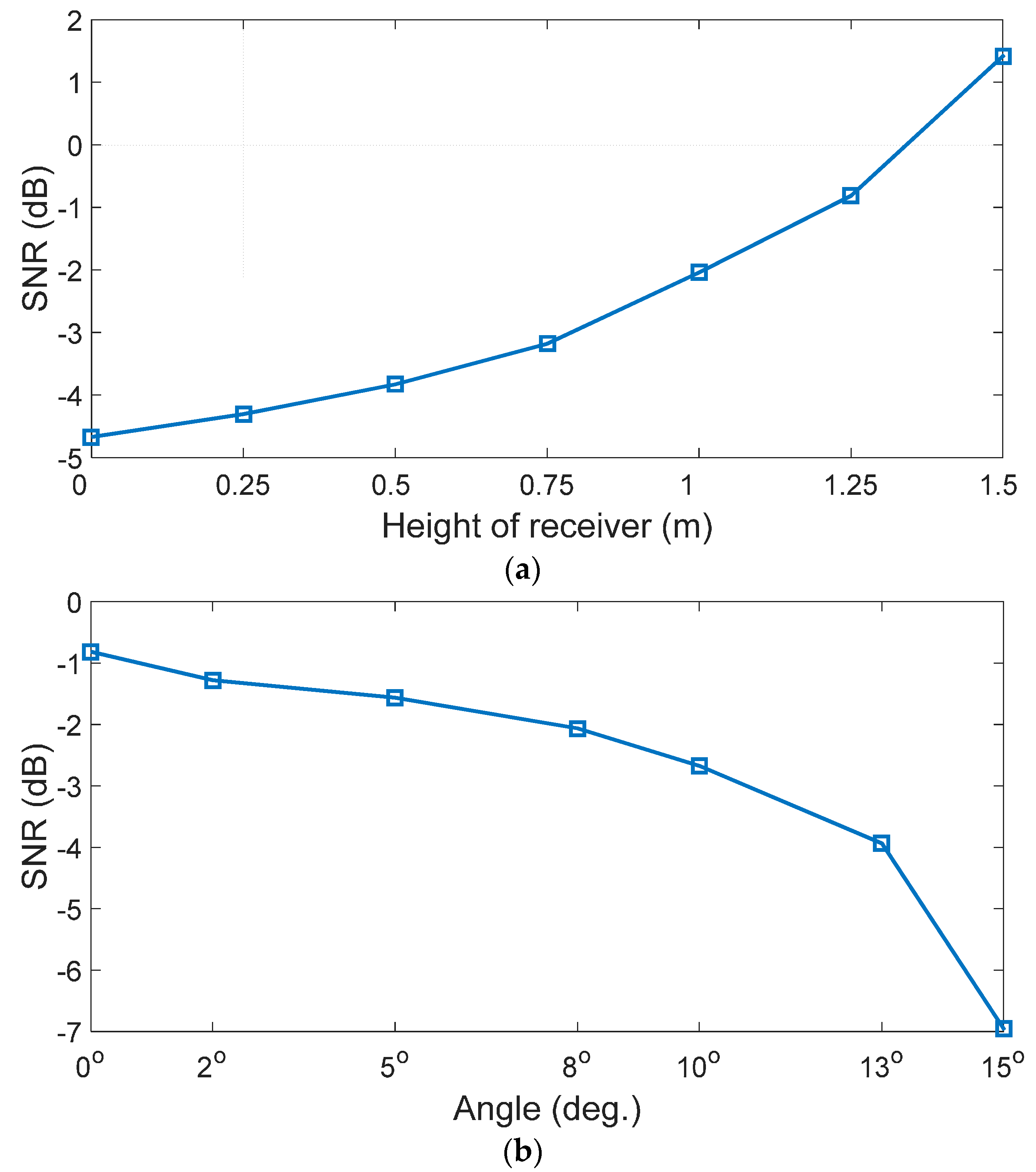
As Figure 5 shows, the distribution of the SNR expresses the performance of the directed light including the ambient light. From these figures, when the distance between the transmitter and the receiver increases or the semi angle increases, the SNR decreases exponentially. At the same height of 1.25 m, we have the same noise power and the maximum SNR is −0.8 dB, while the minimum SNR is −7 dB when the receiver is located at the corner. The 6.2 dB peak-to-trough SNR difference is smaller compared to the scenario when the intersymbol interference is considered, which shows a 22.7 dB peak-to-trough SNR difference [9]. Thus, the VLC systems with an LED under the interference of fluorescent lamps have a small variation of the SNR.
3.2. Proposed Receiver Performance
Figure 6 shows our proposed circuit in great detail. First, we chose Photodiode S5107 (Hamamatsu, Hamamatsu City, Shizuoka Pref., Japan) as the photodetector in our system. For the TIA, VS, and VA stages, the selected op-amps must have a wide bandwidth and a high slew rate to process high-data-rate OOK signals. Therefore, AD8056 (Analog Devices, Norwood, MA, USA) and TLV3501 (Texas Instruments Incorporated, Dallas, TX, USA) were chosen as the high-speed op-amps for these stages and the high-speed comparator, respectively.
The OOK signal was employed to modulate the light signal through the LED. Because of the relationship between the semi angle and the SNR [19], several experiments have been conducted with different semi angles and the same receiver height of 1.25 m to validate the robustness of the performance of our proposed systems with the SNR.
The experimental scenario involves sending the sensor data between two microcontrollers via a universal asynchronous receiver/transmitter (UART). To perform the frequency response test, the microcontroller in the transmitter was programmed to generate a UART signal with the baud rate from 115.2 Kbps to 1 Mbps. At the receiver, the TIA bandwidth was designed for 10 MHz. The experiment was conducted in a room with windows and fluorescent light. The signal output after each stage was observed with the DSO7054A oscilloscope (Keysight, Santa Rosa, CA, USA).
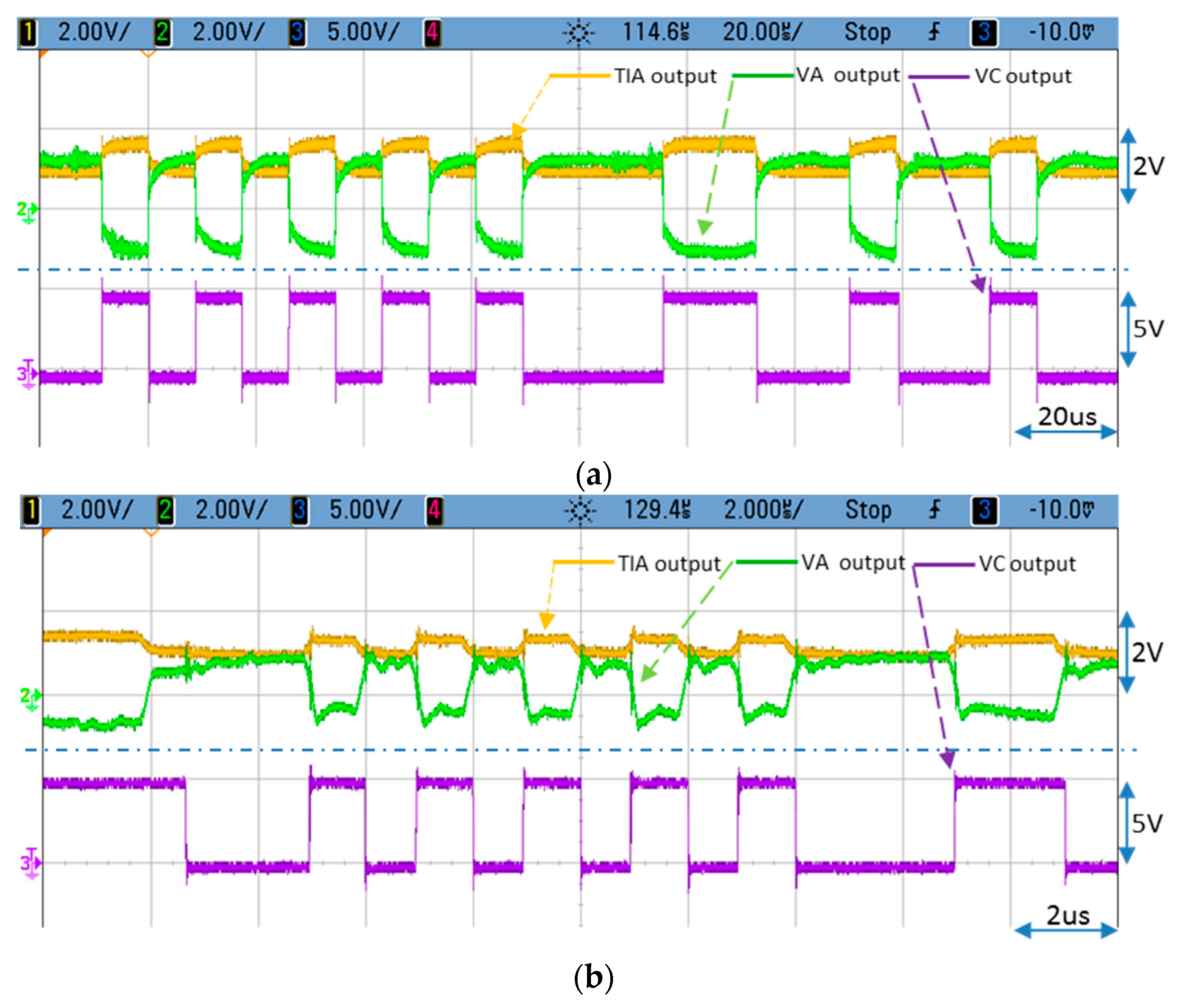
As shown in Figure 7a, the yellow signal consists of a rectangular wave signal and the DC signal is affected by noise. It is shown that the VA output signal has eliminated the average voltage of the signal (DC offset ≈ 0). The final output of the VC stage is the OOK signal that can be retrieved by using a UART. To verify the adaptive feature of the average-voltage detection circuit, the experiment is repeated with the LED under lower illumination condition.
The result in Figure 7b shows that the peak-to-peak amplitude of the signal after the TIA stage is much lower than before, but the DC voltage component remains at the same amplitude because of the same 400-lux indoor condition, dark current, and electrical noise. At a high frequency, we can clearly see the impact of the electrical noise; therefore, we must employ a hysteresis comparator. The better output signal is still obtained. As we mentioned in the introduction section, based on coding for the balance of the number of “0” and “1” bits, the system can operate with 10−6 BER in 2.5 dB SNR condition [3] as the lowest SNR for the conventional receiver. Comparing with −2.7 dB SNR with error-free in our results, the use of simple elements such as LED, PD, TIA, AVT and hysteresis comparators demonstrate a good system for OOK modulated error free communications to high data rates and low S/N ratios.
4. Conclusions
In this study, we analyzed the impact of the distance and the semi angle on the SNR. As can be seen from mathematical formulas, with lower power LEDs under light interference, the semi angle reduction has affected the SNR more than the distance reduction. Moreover, the measured results demonstrate the correctness of this conclusion. From these results, the peak-to-trough SNR difference shows a small variation when compared to the intersymbol interference. Next, we proposed a novel VLC receiver design based on canceling the average voltage. Our circuit design eliminates the effect of the ambient light and amplifies the original signal from the transmitter by greater than 200 times. Several experiments were conducted under different low-SNR conditions to prove that our proposed receiver can operate with a high performance up to 1 Mbps and at an SNR of −2.7 dB being error-free. Thus, we recommend the use of the average-voltage tracking circuit for its advantages over the HPF circuit in terms of performance.
Acknowledgments
This work was supported by a Research Grant of Pukyong National University (2017 year).
Author Contributions
Quan Ngoc Pham, Vega Pradana Rachim, Jinyoung An and Wan-Young Chung conceived and designed the experiments; Quan Ngoc Pham and Vega Pradana Rachim performed the experiments; Quan Ngoc Pham and Jinyoung An analyzed the data; Wan-Young Chung contributed materials and analysis tools; Quan Ngoc Pham wrote the paper.
Conflicts of Interest
The authors declare no conflict of interests.
References
- Karunatilaka, D.; Zafar, F.; Kalavally, V.; Parthiban, R. Based Indoor Visible Light Communications: State of the Art. Commun. Surv. Tutor. 2015, 17, 1649–1678. [Google Scholar] [CrossRef]
- Do, T.-H.; Yoo, M. An in-Depth Survey of Visible Light Communication Based Positioning Systems. Sensors 2016, 16, 678. [Google Scholar] [CrossRef] [PubMed]
- Grobe, L.; Paraskevopoulos, A.; Hilt, J.; Shulz, D.; Lassak, F.; Hartlieb, F.; Kottke, C.; Jungnickel, V.; Langer, K.-D. High-speed visible light communication systems. IEEE Commun. Mag. 2013, 51, 60–66. [Google Scholar] [CrossRef]
- Rajagopal, S.; Roberts, R.D.; Lim, S.-K. IEEE 802.15.7 visible light communication: modulation schemes and dimming support. IEEE Commun. Mag. 2012, 50, 72–82. [Google Scholar] [CrossRef]
- Niaz, M.T.; Imdad, F.; Kim, H.S. Power Consumption Efficiency Evaluation of Multi-User Full-Duplex Visible Light Communication Systems for Smart Home Technologies. Energies 2017, 10, 254. [Google Scholar] [CrossRef]
- Sklavos, N.; Hübner, M.; Goehringer, D.; Kitsos, P. (Eds.) System-Level Design Methodologies for Telecommunication; Springer: New York, NY, USA, 2014. [Google Scholar]
- Chvojka, P.; Zvanovec, S.; Haigh, P.A.; Ghassemlooy, Z. Channel Characteristics of Visible Light Communications within Dynamic Indoor Environment. J. Lightwave Technol. 2015, 33, 1719–1725. [Google Scholar] [CrossRef]
- Pathak, P.H.; Feng, X.; Hu, P.; Mohapatra, P. Visible Light Communication, Networking, and Sensing: A Survey, Potential and Challenges. Commun. Surv. Tutor. 2015, 17, 2047–2077. [Google Scholar] [CrossRef]
- Komine, T.; Nakagawa, M. Fundamental Analysis for Visible-Light Communication System using LED Lights. IEEE Trans. Consum. Electron. 2004, 50, 100–107. [Google Scholar] [CrossRef]
- Ong, Z.; Chung, W.-Y. Long Range VLC Temperature Monitoring System Using CMOS of Mobile Device Camera. IEEE Sens. J. 2016, 16, 1508–1509. [Google Scholar] [CrossRef]
- Rachim, V.P.; Jiang, Y.; Lee, H.S.; Chung, W.-Y. Demonstration of long-distance hazard-free wearable EEG monitoring system using mobile phone visible light communication. Opt. Express 2017, 25, 713–719. [Google Scholar] [CrossRef] [PubMed]
- Do, T.-H.; Yoo, M. Performance Analysis of Visible Light Communication Using CMOS Sensors. Sensors 2016, 16, 309. [Google Scholar] [CrossRef] [PubMed]
- Huynh, P.; Yoo, M. VLC-Based Positioning System for an Indoor Environment Using an Image Sensor and an Accelerometer Sensor. Sensors 2016, 16, 783. [Google Scholar] [CrossRef] [PubMed]
- Huynh, P.; Do, T.-H.; Yoo, M. A Probability-Based Algorithm Using Image Sensors to Track the LED in a Vehicle Visible Light Communication System. Sensors 2017, 17, 347. [Google Scholar] [CrossRef] [PubMed]
- Li, H.; Chen, X.; Huang, B.; Tang, D.; Chen, H. High Bandwidth Visible Light Communications Based on a Post-Equalization Circuit. IEEE Photon. Technol. Lett. 2014, 26, 119–122. [Google Scholar] [CrossRef]
- Lim, K.-H.; Lee, H.-S.; Chung, W.-Y. Multichannel Visible Light Communication with Wavelength Division for Medical Data Transmission. J. Med. Imaging Health Inform. 2015, 5, 1952–1957. [Google Scholar] [CrossRef]
- Tan, Y.Y.; Chung, W.-Y. Mobile health monitoring system through visible light communication. Biomed. Mater. Eng. 2014, 24, 3529–3538. [Google Scholar] [PubMed]
- Wu, F.-M.; Lin, C.-T.; Wei, C.-C.; Chen, C.-W.; Huang, H.-T.; Ho, C.-H. 1.1-Gb/s White-LED-Based Visible Light Communication Employing Carrier-Less Amplitude and Phase Modulation. IEEE Photonics. Technol. Lett. 2012, 24, 1730–1732. [Google Scholar] [CrossRef]
- Hussein, A.T.; Elmirghani, J.M.H. Mobile Multi-Gigabit Visible Light Communication System in Realistic Indoor Environment. J. Lightwave Technol. 2015, 33, 3293–3307. [Google Scholar] [CrossRef]
- Wang, Z.; Yu, C.; Zhong, W.-D.; Chen, J.; Chen, W. Performance of a novel LED lamp arrangement to reduce SNR fluctuation for multi-user visible light communication systems. Opt. Express 2012, 20, 4564–4573. [Google Scholar] [CrossRef] [PubMed]
- Barry, J.R. Wireless Infrared Communications; Kluwer Academic Publishers: Norwell, MA, USA, 1994. [Google Scholar]
- Reference Circuit 1117. Available online: http://www.maximintegrated.com (accessed on 25 November 2016).
Figure 1.
Optical wireless channel model with ambient light noise.

Figure 2.
Conventional visible light communication (VLC) receiver diagram.
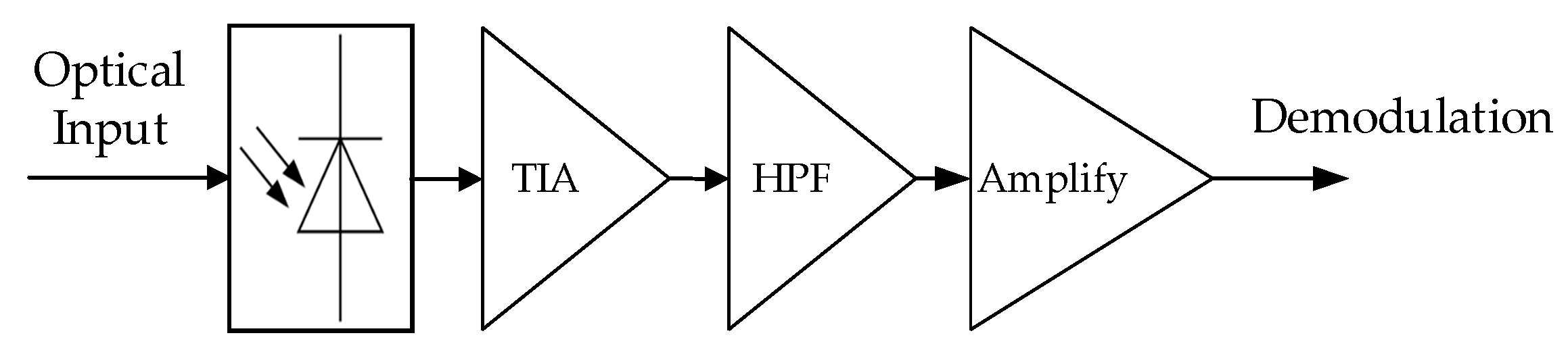
Figure 3.
Proposed VLC receiver diagram.
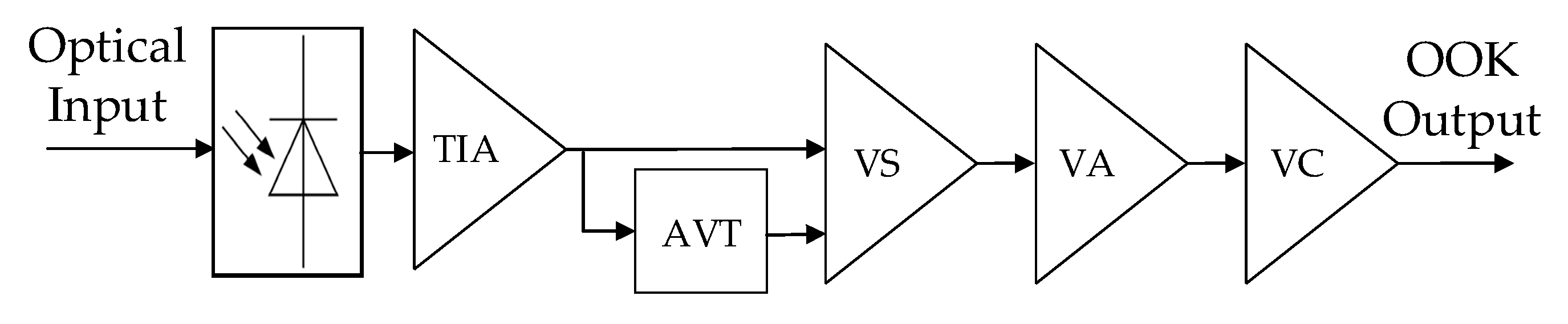
Figure 4.
Experimental setup.

Figure 5.
Signal-to-noise ratio (SNR) distribution: (a) Different distances from the light-emitting diode to the receiver; (b) Different semi angles (no tilting) at 1.25 m.
Figure 5.
Signal-to-noise ratio (SNR) distribution: (a) Different distances from the light-emitting diode to the receiver; (b) Different semi angles (no tilting) at 1.25 m.

Figure 6.
Proposed VLC receiver circuit.
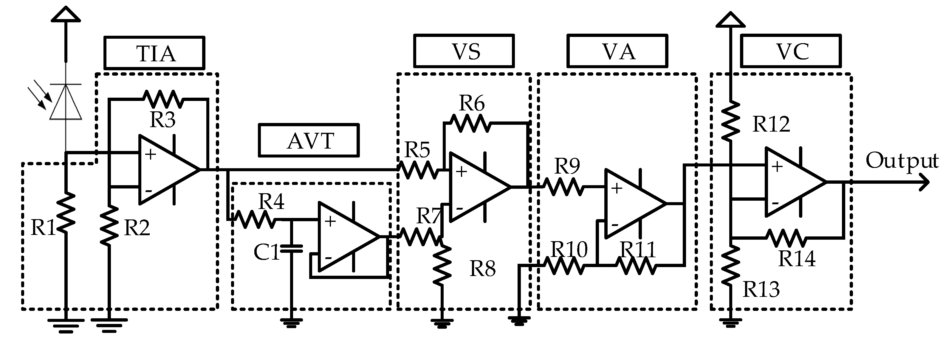
Figure 7.
Output waveforms of the VLC receiver: (a) 115.2 Kbps band rate with the SNR of −0.8 dB; (b) 1 Mbps baud rate with the SNR of −2.7 dB.
Figure 7.
Output waveforms of the VLC receiver: (a) 115.2 Kbps band rate with the SNR of −0.8 dB; (b) 1 Mbps baud rate with the SNR of −2.7 dB.


Table 1.
Experimental parameters.
| Parameters | Experimental Value |
|---|---|
| Room size | 5 m × 5 m × 3 m |
| Numbers of fluorescent lamps | 4 |
| Average ambient power | 43 µW/cm2 |
| Number of LEDs | 1 |
| Height of LED | 2 m |
| Power of LED | 2 W |
| LED’s field of view | 0–20° |
| Height of Receiver | 0 m–1.5 m |
| Modulation method | OOK |
Abbreviation: LED = Light-Emitting Diode; OOK = On-Off Keying.
© 2017 by the authors. Licensee MDPI, Basel, Switzerland. This article is an open access article distributed under the terms and conditions of the Creative Commons Attribution (CC BY) license (http://creativecommons.org/licenses/by/4.0/).
Share and Cite
MDPI and ACS Style
Pham, Q.N.; Rachim, V.P.; An, J.; Chung, W.-Y. Ambient Light Rejection Using a Novel Average Voltage Tracking in Visible Light Communication System. Appl. Sci. 2017, 7, 670. https://doi.org/10.3390/app7070670
AMA Style
Pham QN, Rachim VP, An J, Chung W-Y. Ambient Light Rejection Using a Novel Average Voltage Tracking in Visible Light Communication System. Applied Sciences. 2017; 7(7):670. https://doi.org/10.3390/app7070670
Chicago/Turabian StylePham, Quan Ngoc, Vega Pradana Rachim, Jinyoung An, and Wan-Young Chung. 2017. "Ambient Light Rejection Using a Novel Average Voltage Tracking in Visible Light Communication System" Applied Sciences 7, no. 7: 670. https://doi.org/10.3390/app7070670
Note that from the first issue of 2016, this journal uses article numbers instead of page numbers. See further details here.