
Effects of Tooth Breakage Size and Rotational Speed on the Vibration Response of a Planetary Gearbox


State Key Lab of Power Systems, Department of Thermal Engineering, Tsinghua University, Beijing 100084, China
*
Author to whom correspondence should be addressed.
Appl. Sci. 2017, 7(7), 678; https://doi.org/10.3390/app7070678
Submission received: 1 April 2017
/
Revised: 19 May 2017
/
Accepted: 13 June 2017
/
Published: 1 July 2017
(This article belongs to the Section Mechanical Engineering)
Abstract
:A nonlinear dynamic model for a planetary gearbox with tooth breakage fault is built based on an improved rigid multibody model, and the effects of tooth breakage size and rotational speed on the vibration response of the planetary gearbox are investigated numerically and experimentally. A time-varying mesh stiffness model of planetary gears with tooth breakage fault is established. Dynamic simulations of a healthy planetary gear and seven fault gears with different breakage sizes under several rotational speeds are carried out. Experiments for healthy, half tooth breakage fault and whole tooth breakage fault planetary gears under several rotational speeds are performed. Amplitude analysis, spectrum analysis and envelope spectrum analysis are applied on the numerical and experimental vibration signals. The dynamic model is validated by experiment. The analysis results reveal the resonance and modulation characteristics in the vibration response, and the law of the vibration changes with breakage size and rotational speed.
1. Introduction
The planetary gearbox is used in wind turbines because of its advantages, including high power density, compactness, etc. However, it suffers a high failure rate due to its complex structure and the time-varying working load [1]. The common gear failure modes include crack, pitting, wear, spalling and breakage. Figuring out the dynamic characteristics of these faults is of great importance for reducing equipment downtime and maintenance expenditure and improving the safety by providing an early warning of potential catastrophic failure [2].
Many research works have been done on the dynamics behaviors of the planetary gearbox. Iglesias et al. developed a hybrid method of the analytical solution and the finite element model for the contact force calculation [3], and they studied the effect of manufacturing errors such as eccentricity and planet pin positioning errors on the load sharing behavior of a three-planet planetary transmission [4]. Sun et al. built a lumped-parameter model of a two-stage helical planetary gear transmission system and studied the dynamic sensitivity of the load-sharing coefficient to errors [5]. Gravity has an important effect on the dynamics of the wind turbine gearbox because of its great size. Qiu et al. numerically studied the effects of gravity, ring support stiffness and bed plate tilt angle on the load-sharing characteristics of the planetary gear in horizontal axis wind turbines [6]. Parra and Vicuña used two different models, the phenomenological model and the lumped-parameter model, to study the frequency content of planetary gearbox vibrations under non-fault and different fault conditions [7]. Liang et al. developed a two-dimensional lumped mass model to simulate the vibration signals of a planetary gear set in the perfect and crack situations; amplitude modulation can be found in the resultant vibration signals; sidebands appeared in the vibration spectrum and can used for fault detection. Chen and Shao studied the influences of cracks on the mesh stiffness and the dynamic performance of the planetary gear set [8]. Some other research works on the dynamics of planetary gearbox are [9,10,11].
Gearbox dynamic models vary from considering only torsional vibration [12] to the multibody model with lateral-torsional vibration coupled [13,14,15]. This paper focus on the vibration characteristics of the planetary gear with a planet gear tooth broken. Tooth breakage leads to the reduction of the time-varying gear mesh stiffness and the incensement of mass unbalance, and these excitations will affect the gears dynamic behavior and then the generated vibration [16,17]. Compared with the flexible multibody model, the rigid multibody model can obtain an acceptable result with a much lower time cost [18], so it was most widely used in the tooth breakage fault research.
Chaari et al. [19] proposed an analytical method to quantify the reduction of gear mesh stiffness due to tooth breakage fault. Their model considered bending, fillet-foundation and contact deflection, but it was only used for a single stage spur gear transmission. Tian et al. [20] derived an expression of the effective mesh stiffness of the mating gears with tooth breakage fault, based on the fact that tooth breakage causes a great drop and rise at the transition points of single/double-tooth-pair mesh. Combining the fault model with a coupled lateral and torsional vibration model of a one-stage spur gear pair, they found that the properties of the vibration response of a gear pair with tooth faults were consistent with the variations of mesh stiffness. Jiang and Liu. [21] developed a three-dimensional analytical helical gear pair model considering the mass eccentricity and mesh stiffness induced by tooth breakage with sliding friction. The effects of the tooth breakage shape and size on the mesh stiffness and dynamic responses of a helical gear pair were calculated. Their results revealed that the rotational frequency increases significantly when considering the mass eccentricity induced by the tooth breakage defect. Li et al. [22] studied the vibrational mechanisms and frequency features of a single-stage parallel gearbox under several fault states using a rigid multibody dynamic model, and they explained the cause of high-order mesh frequency harmonics and the asymmetrical modulation sidebands.
These tooth breakage fault research works focused on parallel gear stages, while the vibration of the planetary gear is much more complex, because the driving flanks consist of multiple external contact (sun-planet) pairs and internal contact (ring-planet) gear pairs [23]. Gui et al. [24] established a rigid multibody model of a planetary gear system with tooth breakage defect and pointed out the effects of the length of tooth breakage on the dynamic response. Gui et al. [25] investigated the tooth breakage fault on the wind turbine planetary gear system considering the gear manufacturing errors by numerical and experimental research. They found that the sidebands of the planetary gear system become much more complex when manufacturing errors are taken into consideration and that different tooth breakage faults could be located by monitoring the values of their characteristic frequencies.
Among these research works, few of them studied the dynamics of the planetary gearbox with tooth breakage fault under different rotational speed conditions. Due to the unstable wind conditions, frequent low speed start and emergency brakes, the rotating speed is nonstationary [26]. The planetary gear rigid multibody model adopted in these works uses a rotating frame as its reference frame [27], so in order to use this model, the premise of constant rotating speed was applied first based on the assumption that if the concerned time period is small, the work condition of the gearbox could be considered as quasi-stable [25]. The solutions of the traditional model are referred to the rotatory reference frame and need to be decomposed into a fixed reference frame. Methods are varied; for example, Parra and Vicuña proposed a frame decomposition methodology [7], while Liang et al. [28] use the summation of the weighted vibration of each planet gear as the sensor measurements. We proposed an improved rigid multibody model for the planetary gearbox, which can handle the varying rotational speed directly [29]. In this paper, a dynamic model for a planetary gearbox with tooth breakage fault is built based on this model and validated by experiment. The effects of the tooth breakage size and the rotational speed on the vibration of the planetary gearbox are investiaged by numerical simulation and experiment.
2. Nonlinear Dynamic Model of the Planetary Gearbox Considering Nonlinear Mesh Stiffness
A planetary gear stage mainly consists of a carrier, a ring gear, a sun gear, several planet gears and bearings. The structure of a planetary gear stage with three planets is shown in Figure 1.
In the improved rigid multibody model in [29], the reference frame for the carrier, the ring and the sun gear is the inertial frame, and the reference frame of each planet gear is a moving frame. The origin of the moving frame is at the center of the planet. The frame revolves around the sun gear and rotates with the same speed, and the revolution speed is equal to the instantaneous rotational speed of the carrier. Equation (1) shows the dynamic model in matrix form,
in which matrices , , can be obtained using the element assembly method given in [29]. Depending on the mesh stiffness of all of the gear pairs and the stiffness of all of the bearings, the total stiffness matrix is time varying. The stiffness of bearings is modeled as six independent linear springs in this paper.
The instantaneous mesh stiffness of a gear tooth pair k is determined by many factors, including manufacturing errors, assembly errors, the instantaneous motions, etc. The simplified dynamic time-varying mesh stiffness model in [29] is used in this paper, in which the transmission error is omitted and mesh phase relationships among the sun-planet and ring-planet meshes are considered. A brief description of the mesh stiffness model is presented below for completeness of the paper.
To describe the mesh state of a meshing gear tooth pair, a relative contact position X for a meshing tooth pair is defined as,
where is one of the gears’ instantaneous rotation angular displacements, A and B represent the position where the tooth steps into and steps out of the current mesh process and and represent their corresponding rotation angular displacements. For the active gear in a spur gear pair, the mesh starting point A is near the root of the tooth, while for the passive gear, it is located at the top of the tooth. For a helical gear pair, the relative contact position is proportional to the length of the contact line. Transmission error is omitted in this paper, i.e., points A and B of each tooth keep the same among all of its mesh process, and thus, the nonlinear mesh stiffness of a tooth pair k only depends on its contact position. For a healthy gear tooth pair, a parabola is used to fit its stiffness , shown as,
where e is the contact ratio, represents the mean mesh stiffness and and represent the maximum and minimum mesh stiffness, respectively. In this paper, the and are estimated by Equation (4),
where for an external spur gear pair, for an internal spur gear pair and for a helical gear pair.
Since differences may exist among the teeth of the same gear, the teeth should be numbered, and the number of teeth in meshing should be considered in the mesh stiffness k. Denote the tooth pair mesh stiffness as , where are the number of the two teeth in meshing. For all of the healthy gear pairs,
In a gear pair, several tooth pairs may mesh at the same time. Denote all of these mesh tooth pairs and their corresponding contact status as . For a mesh gear pair, a mesh tooth pair that satisfies always exists. The contact position of this tooth pair can be calculated by Equation (6),
where the subscript , or 2 represents the i-th gear of the gear pair, is the gear’s instantaneous rotation angular displacement and is its initial value. For a planetary gear, i in Equation (6) could take the number of the planet gear as its value. The corresponding numbers of the two teeth can be calculated by Equation (7),
where is the number of the teeth in meshing at start and is the number of the total teeth.
For a parallel gear pair, we can set , while phase relationships among the sun-planet gear pairs and ring-planet gear pairs should be considered in a planetary gear. gear pairs and initial tooth numbers needed to be determined, where N is the total number of the planet gears. Donate these tooth numbers as , where the subscript is the gear pair, p is the number of the planet, r represents the ring and s represents the sun gear; the subscript i is the gear, in which represents the center gear, i.e., the sun gear or the ring gear, and represents the planet gear. Here, we set , , , then the other numbers can be calculated by:
where , and depend on the tooth number of the gears and the layout of the planet gears. In this paper, we take,
Based on the mesh tooth pair calculated by Equations (6) and (7), all of the mesh tooth pairs and their corresponding contact position can be obtained by:
where represents all the integers between 0 and .
Denote the total number of the teeth pairs in meshing as , then the instantaneous mesh stiffness of this gear pair can be calculated by:
3. Time-Varying Mesh Stiffness Model of Planetary Gears with Tooth Breakage Fault
In this section, a time-varying mesh stiffness model of planetary gears with tooth breakage fault is proposed. The tooth breakage fault studied in this paper is shown as Figure 2. The shape of the breakage section is assumed to be a rectangle and parallel to the axis of the gear, which is similar to the model in [21].
Define a contact rotation angular displacement L as the angular displacement of the gear from the tooth step into the meshing process to the tooth step out when it is healthy. The size of the tooth breakage p is defined as,
where L represents the contact rotation angular displacement of a healthy tooth and represents the loss of the contact rotation angular displacement when the tooth is broken. It can be found that the breakage size p satisfies . means the tooth is healthy; means half of the tooth is broken; and means the tooth is totally broken.
The mesh stiffness between the broken tooth and a healthy tooth will drop to zero at the contact position from the broken position to the top of the tooth. When the tooth breakage fault is located at the active gear, the tooth pair mesh stiffness can be modeled as:
where is the healthy gear pair mesh stiffness defined in Equation (3). Taking this model into Equation (10), the nonlinear mesh stiffness model for a gear pair with one tooth broken is obtained as Equation (14),
where is the number of the broken teeth on the planet gear. Thus, the nonlinear dynamic model for a planetary gear with one tooth broken is established.
In the numerical research of the tooth breakage fault, the planetary gearbox in [29] was used. The transmission ratio of the planetary gear ratio is about 4.56, and its detailed parameters are listed in Table 1. The fault is located at the first tooth of its first planet.
The natural frequencies of the gearbox calculated by the improved model are listed in Table 2. There are six rotational frequencies and six translational frequencies in total [30]. Natural frequencies will be used in the vibration signal analysis.
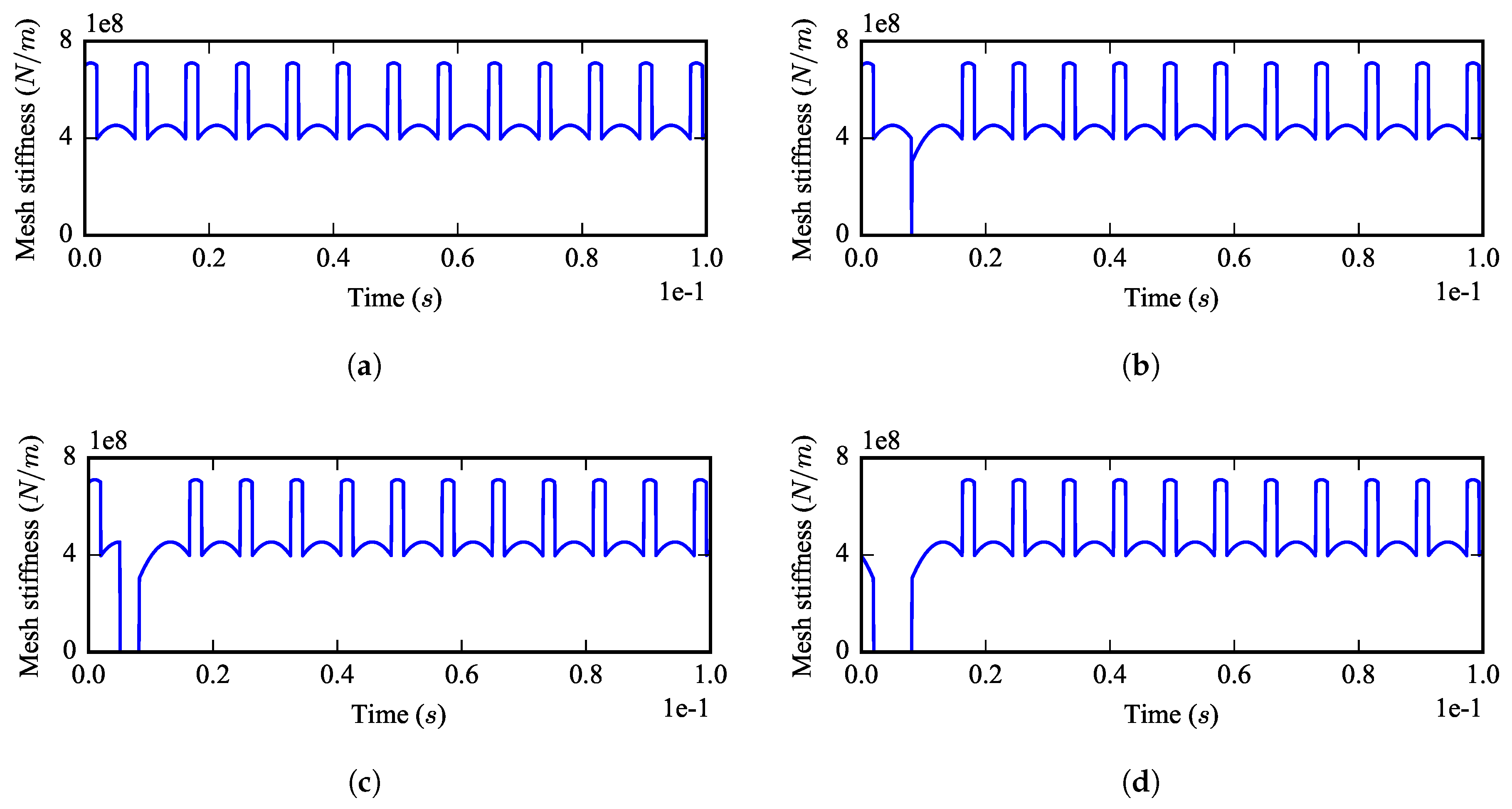
Figure 3 shows four time-varying mesh stiffnesses in the planetary gear simulated by the stiffness model of Equation (14). The corresponding carrier rotational speed is constant in time rpm, and the breakage size . It can be found that periodic impulses exist in the time-varying mesh stiffness between the fault planet gear and the center gears, and a phase shift exists between the mesh stiffness impulse of the sun-planet gear pair and the impulse of the ring-planet gear pair.
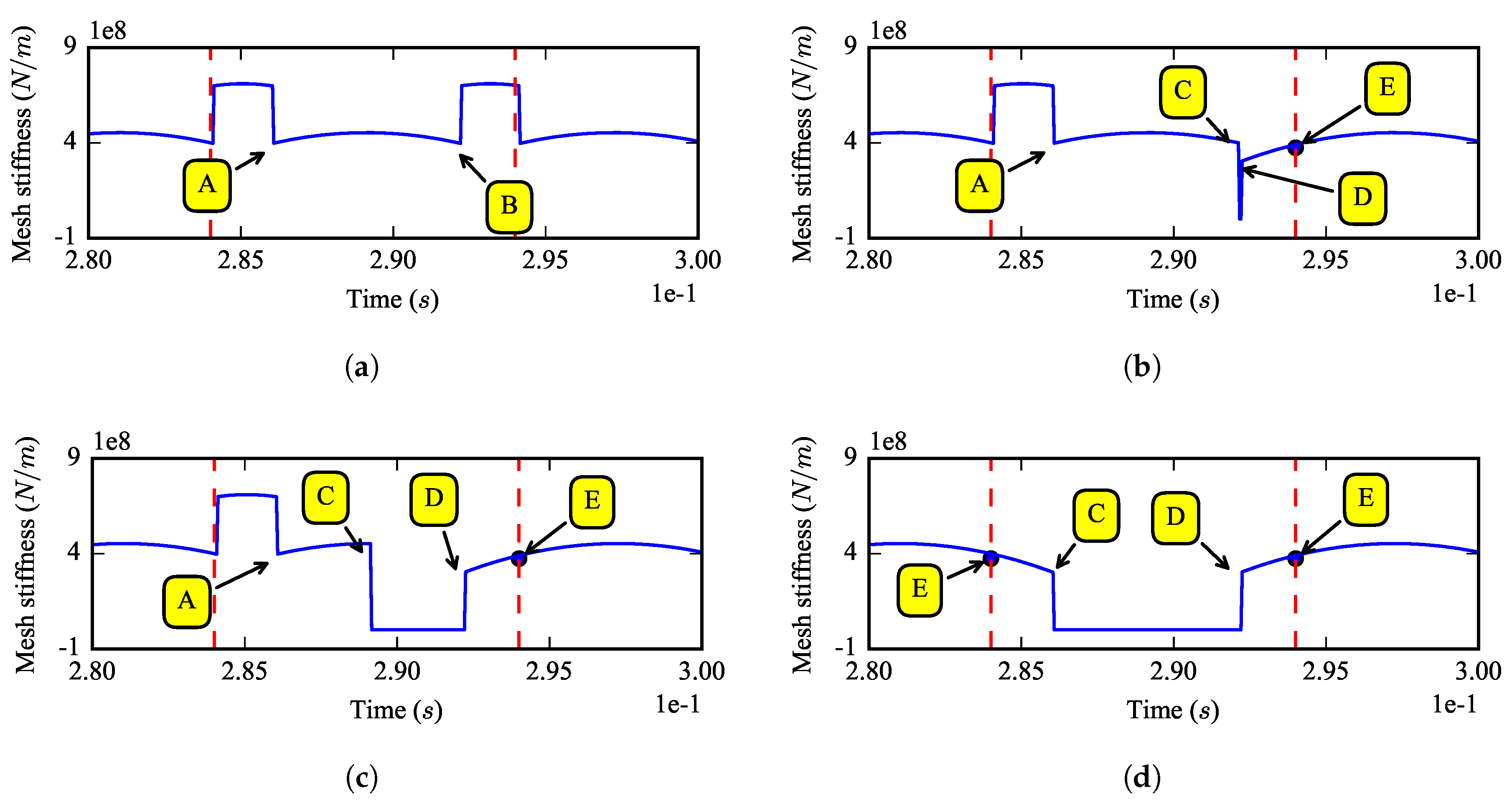
Figure 4 shows the mesh stiffness of the sun-fault planet gear pair with different breakage sizes. All of the carrier rotational speeds are the same, rpm. It can be found that the width of the impulse becomes bigger with the breakage size increasing.
Figure 5 gives the partial enlarged views of the mesh stiffness in Figure 4, where A, B, C, D represent different impact modes caused by the sudden change of the total number of teeth pairs in mesh. At point A, the number of the mesh teeth is changing from two to one; at point B, is changing from one to two; at point C, is changing from one to zero; at point D, is changing from zero to one; at point E, the resultant borne by each gear has a sudden change. These impact patterns reveal the effects of the breakage size on meshing stiffness.
4. Dynamic Simulation of the Tooth Breakage Fault
In this section, the dynamic simulation of a healthy planetary gear and seven fault gears is conducted. The breakage sizes p are 0, 0.1, 0.2, 0.5, 0.7, 0.8, 0.9 and 1.0, respectively. In this paper, the gear with is called the healthy gear; a fault gear with is called the half tooth breakage fault gear; and the fault gear with is called the whole tooth breakage fault gear. The driving torque applied on the carrier is constant in time,
and the load torque on the sun gear is set to,
where represents the transmission ratio of the planetary gear; C is the setting speed of the carrier and its unit is ; the initial state of all of the DOFs is zero; and is the time when the carrier rotational speed reaches the speed C for the first time. Based on the given loads of Equations (15) and (16), it can be found by qualitative analysis that the rotational speeds of the carrier, the sun gear and the planet gears will increase almost linearly until time , at which the load on the sun gear starts to join and the rotational speed of the carrier will ultimately fluctuate around speed C, approximately. The time can be estimated by,
where is the total inertia of the planetary gear cast on the carrier side. The time can be used for the simulation result checking. For the gearbox in Table 1, .
Seven setting speeds are simulated for each gearbox; hence, 56 simulations in total are conducted in this paper. These setting speeds are listed in Table 3, where , and represent the rotational frequency of the carrier, the sun gear and the planet gear respectively, and represents the mesh frequency. is also the fault characteristics frequency in this paper.
The damping matrix in Equation (1) is built by the Rayleigh damping model, and the coefficients of Rayleigh damping are chosen as , in this paper. The implicit Newmark algorithm is adopted to solve the nonlinear dynamic model [29]; the time step is s. A virtual acceleration sensor is installed on the ring to collect its vertical vibration, and the data sampling rate is 40 kHz. In this paper, the signal is synthesized by,
where is the vertical acceleration of the ring gear, is the rotational acceleration of the ring gear and is the radius of the ring gear. Noises are ignored in this paper.
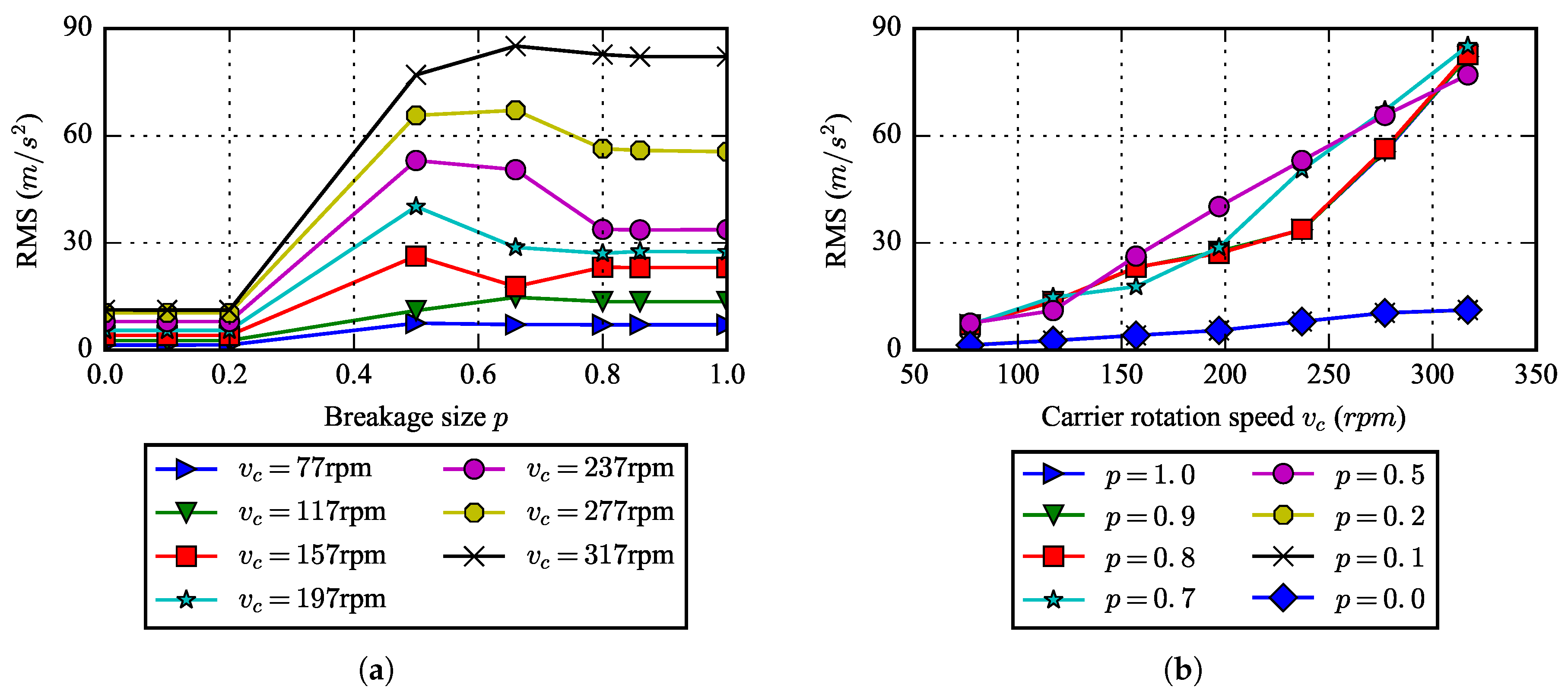
The time length of each simulation is five seconds. The data at the last four seconds are used for analysis. Figure 6 shows the changes of the root mean square (RMS) of the ring vertical acceleration versus breakage size and rotational speed. From Figure 6a, it can be found that, under some rotational speeds, the RMS does not increase monotonously with the increasing of the breakage size, and at some speeds, the RMS corresponding to the whole tooth breakage fault may be less than the RMS corresponding to a half tooth breakage fault. For example, when rotational speed is set to 197 rpm, the half tooth breakage fault gear with has the largest vibration RMS. It can be found from Figure 6b that, for the healthy gear, the RMS is almost linearly increasing with the rotational speed due to the increasing of the external load, while for the fault gears, the RMSs are nonlinearly increasing with the rotational speed. The RMS of the fault gears are larger than the RMS of the healthy gear under any rotational speed.
The healthy gear, the half tooth breakage fault gear with and the whole tooth breakage fault are chosen for vibration comparative analysis. The carrier rotational speed chosen here is 237 rpm. Figure 7 shows the waveform of these three acceleration signals. Compared with the signal under the healthy state in Figure 7a, the effect of the half tooth breakage fault on the vibration is slight. However, when the whole tooth is broken, strong impacts can be observed, and the peak value of the signal has increased nearly forty-fold.
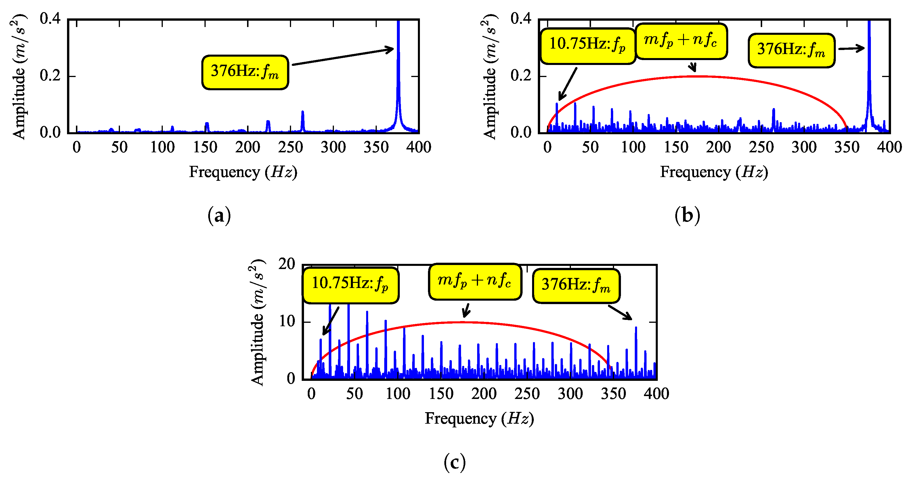
The spectrum of the vibration signals is shown in Figure 8. It can be found that there is an outstanding component at about 2632 Hz; this frequency equals to 7 and is near the fourth rotational natural frequency of 2662.8 Hz, so this is a typical harmonic resonance phenomenon. There is a sideband at the high frequency region with the frequency interval of , which is caused by modulation. The spectrum of the half tooth breakage fault is close to the spectrum of the healthy gear; thus, it is hard to recognize the tooth breakage fault only only with spectrum analysis when the breakage size is small. However, as shown in Figure 8c, new sidebands caused by the fault become very obvious when the whole tooth is broken.
Due to the existence of resonance and modulation in the vibration signals, demodulation is necessary in gear tooth breakage fault feature extraction. Figure 9 shows the envelope spectrum of the three signals at the low frequency region. From Figure 9a, one can see that the mesh impact is the main excitation source when the gearbox is healthy. From Figure 9b,c, it is clear to find that, when a planet gear tooth breakage fault occurs, the sum- and difference-frequency of the rotational frequency between carrier and the fault characteristic frequency will occur in the envelope spectrum. This is a useful indicator for the fault detection.
5. Experimental Research of the Planet Tooth Breakage
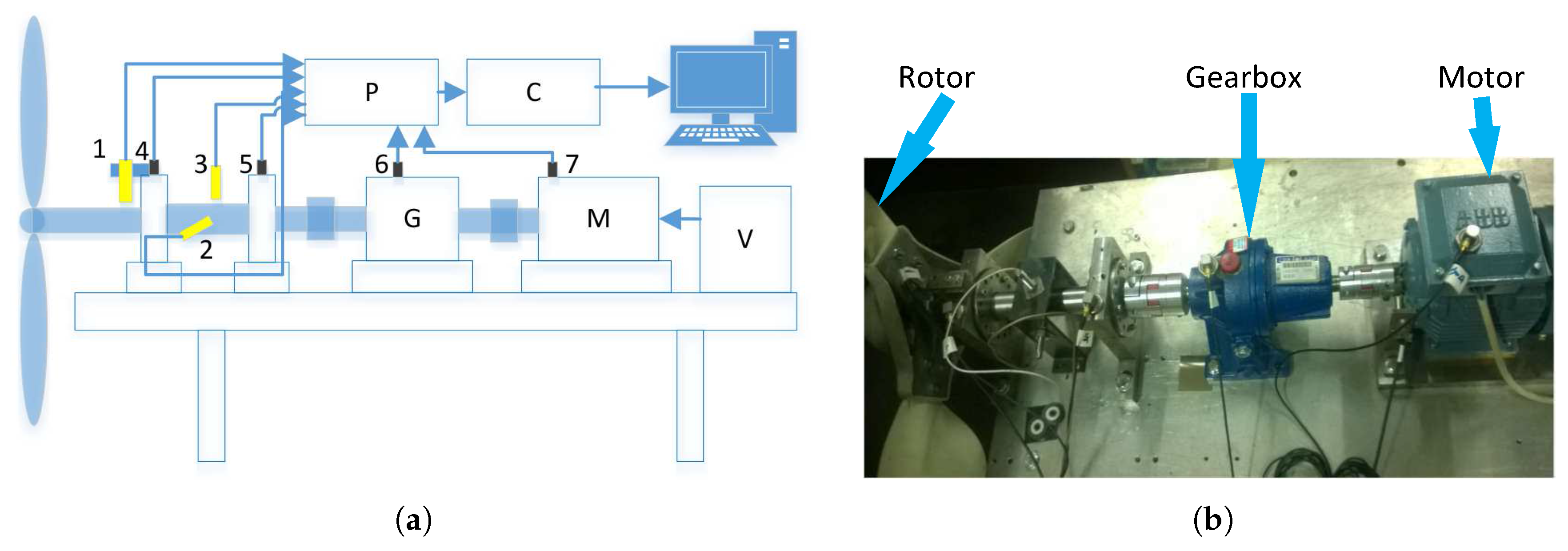
In order to check the validity of the simulation results in the previous section and investigate the fault characteristics, experiments for planetary gears with planet gear tooth breakage fault are performed. Figure 10 shows the structure of the test rig. The test rig mainly consists of a wind rotor, a planetary gearbox, an electrical motor, a variable-frequency drive, shafts and bearings. The electrical motor provides the driving power, and the rotor provides load. The planetary gearbox is single stage and has three planetary gears. The overall structure of the gearbox used in experiments and the gearbox used in simulations are the same as shown in Figure 1, but their detailed parameters are different. For the experimental gearbox, the tooth number of the sun gear , the tooth number of the planet gear , the tooth number of the ring gear and the transmission ratio is about 3.577. There are seven sensors installed shown in Figure 10a, while only the gearbox vertical acceleration signal is analyzed in this paper.
Three sets of experiments with a health planetary gear and two fault gears are carried out. As shown in Figure 11, the two fault gears are a half tooth breakage fault gear and a whole tooth breakage fault gear, in which the broken tooth is located at the planet gear at right side.
Same as the simulation, each experiment is carried out at seven different rotational speed conditions listed in Table 4, in which the symbols have the same meaning as the symbols in Table 3. Five groups of data are collected under each condition. The sampling rate is 25 kHz, and the time length of each sample is four seconds.
Figure 12 shows the average RMS of the ring vertical acceleration varying with rotational speed in three experiments. An obviously rising trend can be found for all of the RMSs. Moreover, under the same rotational speed condition, the RMSs of both fault gears are greater than the RMS of the healthy gear. The simulation results in Figure 6b agree well with these experimental results.
Take the gearbox vertical acceleration signals at the rotational speed of 237 rpm for further analysis. According to Table 4, the rotational frequency of the carrier is about 4 Hz; the fault characteristic frequency of the gearbox is about 13.2 Hz; the rotational frequency of sun gear is about 14.1 Hz; and the mesh frequency is about 265 Hz.
Figure 13 shows the waveform of the three signals corresponding to the simulation results in Figure 7. From Figure 13a, one can find that periodic impulse components exist in the vibration of the healthy gear; they were caused by the gear meshing and slight shaft misalignment in the test rig. From Figure 13b, it can be found that the vibration waveform of the half tooth breakage fault gear is similar to that of the healthy gear, and the peak-to-peak value has a very small increase. For the whole tooth breakage fault gear in Figure 13c, strong impacts can be observed, and the peak-to-peak value increases significantly. These phenomena validate the simulation results in Figure 7c.
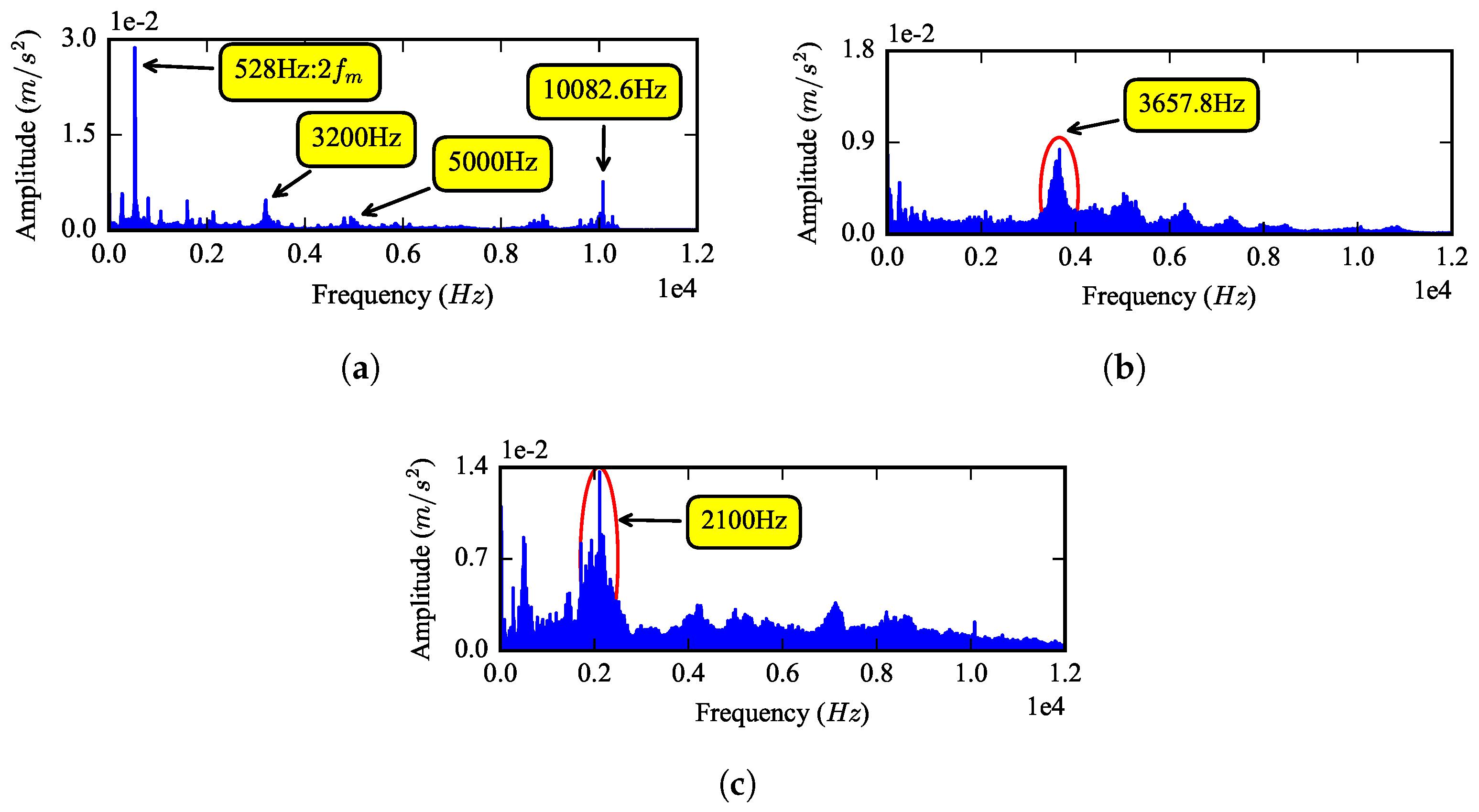
Figure 9 shows the spectrum of these three signals. From the spectrum of the healthy gear in Figure 14a, an outstanding component at about 528 Hz can be found, which equals 2. This phenomenon is very similar to the harmonic resonance at 2632 Hz in Figure 8a; thus, one can infer that the test rig has an natural frequency of around 528 Hz. For the half tooth breakage fault gear in Figure 14b, the sidebands around 3657.8 Hz become obvious. For the whole tooth breakage fault, the sidebands around 2100 Hz become more obvious and dominant. The frequency distribution of the simulated vibration signal in Figure 8 is similar to the experimental results in Figure 14c.
One of the main difference between the experiment results in Figure 9 and the simulation results in Figure 8 is the effect of the gear mesh on the gearbox vibration. In the healthy gear simulation, the mesh impact is the only excitation source, and the damping is simplified, which make the low frequency region of the spectrum clean and the octaves of mesh frequency outstanding. In the experiment, other excitations, caused by shaft misalignment, bending, etc., exist at the same time, which reduce the effect of the gear mesh.
Figure 15 shows the partial enlarged view of the spectra. It can be found that the carrier rotational frequency and the sun gear rotational frequency can be observed from the spectrum directly; however, the fault characteristic frequency cannot be observed from the low frequency region of the spectrum directly.
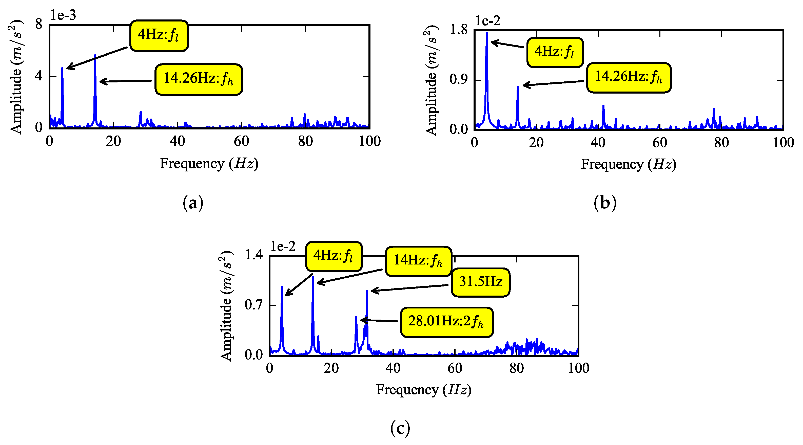
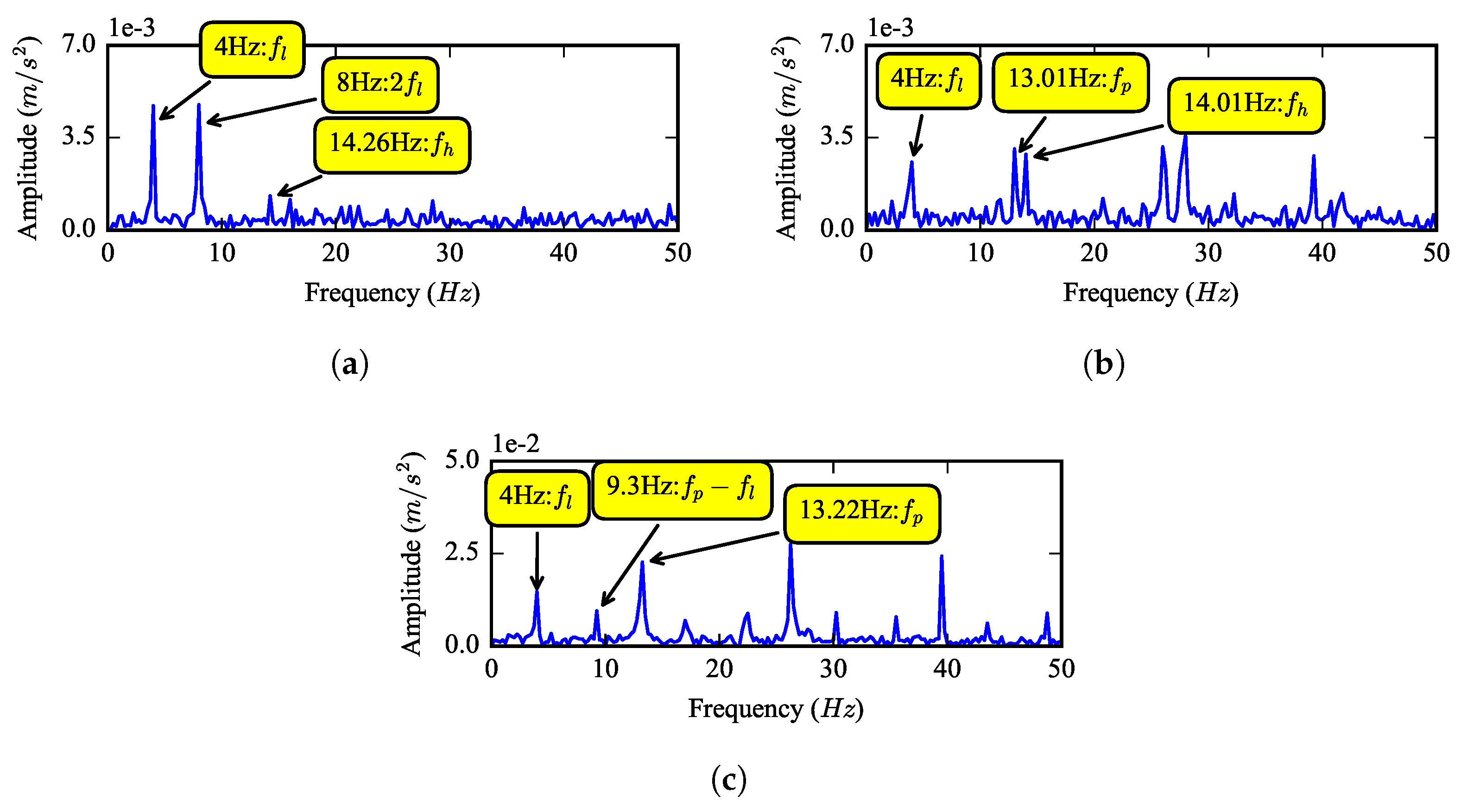
According to the simulation results, demodulation is needed to detect the tooth breakage fault. Resonance demodulation analysis (DRA) is used here. At first, a band-pass filter is used to process the vibration signal with the frequency range chosen as 1700 to 2500 Hz, then the envelope spectrum of the filtered signal is calculated. Figure 9 shows the envelope spectrum of the three signals at 0 to 50 Hz. The rotational frequency of the carrier Hz, the rotational frequency of the sun gear Hz and their octaves can be found in all of these spectra. No other frequencies exist when the gear is healthy, shown as Figure 16a. For the half tooth breakage fault in Figure 16b, the fault characteristic frequency Hz and its octaves can be clearly observed. For the whole tooth breakage fault in Figure 16c, a difference-frequency between and can also be found. Consequently, the simulation result that sum- and difference-frequency between and exist in the envelope spectrum of the fault gear vibration signal is validated by the experiment.
6. Conclusions
A nonlinear dynamic model for a planetary gearbox with tooth breakage fault is built based on an improved rigid multibody model and is validated by experiment. The effects of tooth breakage size and rotational speed on the vibration response of a planetary gearbox with tooth breakage fault are investigated. Tooth breakage fault causes a great drop and rise at the transition points of the gear mesh, leading to an impulse in the time-varying mesh stiffness; the width of the impulse becomes wider with the breakage size increasing. For the healthy gear, the effects of the mesh can be found both from the spectrum and envelope spectrum directly; the rotational frequency of the carrier and sun gear also appears in the low frequency region of the spectrum because of factors such as misalignment, unbalance, etc. Harmonic resonance phenomenon can be found both in simulation and experiment. When the tooth breakage fault occurs, the RMS of the vibration signal will increase, while under some rotational speeds, the RMS does not increase monotonously with the increasing of breakage size, and at some speeds, the RMS caused by the whole tooth breakage fault may be less than the RMS caused by a half tooth breakage fault. In the spectrum, the fault characteristic frequency cannot be found directly; demodulation is needed, and the sum-and difference-frequency between the carrier rotational frequency and the fault characteristic frequency can be detected from the low frequency region of the envelope spectrum.
In the future, other excitations caused by manufacturing error, misalignment, unbalance, etc., will be considered in the dynamic model, to make the simulation better coincide with the actual situation.
Acknowledgments
This work was supported by the National Natural Science Foundation of China (Grant 51174273).
Author Contributions
Wenguang Yang designed the methods and validation the schemes under the supervision of Dongxiang Jiang. Wenguang Yang gathered and analyzed the experimental data. Wenguang Yang wrote the paper. Te Han reviewed and edited the manuscript. All authors contributed to discussing and revising the manuscript.
Conflicts of Interest
The authors declare no conflict of interest.
References
- Daneshi-Far, Z.; Capolino, G.A.; Henao, H. Review of failures and condition monitoring in wind turbine generators. In Proceedings of the 2010 XIX International Conference on Electrical Machines (ICEM), Rome, Italy, 6–8 September 2010; pp. 1–6. [Google Scholar]
- Singh, A.; Houser, D.R.; Vijayakar, S. Detecting Gear Tooth Breakage Using Acoustic Emission: A Feasibility and Sensor Placement Study. J. Mech. Des. 1999, 121, 587–593. [Google Scholar] [CrossRef]
- Iglesias, M.; Rincon, A.F.D.; De-Juan, A.; Diez-Ibarbia, A.; Garcia, P.; Viadero, F. Advanced model for the calculation of meshing forces in spur gear planetary transmissions. Meccanica 2015, 50, 1–26. [Google Scholar] [CrossRef]
- Iglesias, M.; Rincon, A.F.D.; De-Juan, A.; Garcia, P.; Diez-Ibarbia, A.; Viadero, F. Planetary transmission load sharing: Manufacturing errors and system configuration study. Mech. Mach. Theory 2017, 111, 21–38. [Google Scholar] [CrossRef]
- Sun, W.; Li, X.; Wei, J.; Zhang, A.; Ding, X.; Hu, X. A study on load-sharing structure of multi-stage planetary transmission system. J. Mech. Sci. Technol. 2015, 29, 1501–1511. [Google Scholar] [CrossRef]
- Qiu, X.; Han, Q.; Chu, F. Load-sharing characteristics of planetary gear transmission in horizontal axis wind turbines. Mech. Mach. Theory 2015, 92, 391–406. [Google Scholar] [CrossRef]
- Parra, J.; Vicuña, C.M. Two methods for modeling vibrations of planetary gearboxes including faults: Comparison and validation. Mech. Syst. Signal Process. 2017, 92, 213–225. [Google Scholar] [CrossRef]
- Chen, Z.; Shao, Y. Dynamic simulation of planetary gear with tooth root crack in ring gear. Eng. Fail. Anal. 2013, 31, 8–18. [Google Scholar] [CrossRef]
- Zhu, C.; Xu, X.; Liu, H.; Luo, T.; Zhai, H. Research on dynamical characteristics of wind turbine gearboxes with flexible pins. Renew. Energy 2014, 68, 724–732. [Google Scholar] [CrossRef]
- Jammal, A.; Rong, Y. Wind turbine gearbox dynamics. In Proceedings of the 2013 IEEE International Symposium on Assembly and Manufacturing (ISAM), Xi’an, China, 30 July–2 August 2013; pp. 330–333. [Google Scholar]
- Guo, Y.; Keller, J.; Parker, R.G. Nonlinear dynamics and stability of wind turbine planetary gear sets under gravity effects. Eur. J. Mech. A Solids 2014, 47, 45–57. [Google Scholar] [CrossRef]
- Girsang, I.P.; Dhupia, J.S.; Muljadi, E.; Singh, M.; Pao, L.Y. Gearbox and Drivetrain Models to Study Dynamic Effects of Modern Wind Turbines. IEEE Trans. Ind. Appl. 2013, 50, 874–881. [Google Scholar]
- Kahraman, A.; Kharazi, A.A.; Umrani, M. A deformable body dynamic analysis of planetary gears with thin rims. J. Sound Vib. 2003, 262, 752–768. [Google Scholar] [CrossRef]
- Abousleiman, V.; Velex, P. A hybrid 3D finite element/lumped parameter model for quasi-static and dynamic analyses of planetary/epicyclic gear sets. Mech. Mach. Theory 2006, 41, 725–748. [Google Scholar] [CrossRef]
- Saada, A.; Velex, P. An extended model for the analysis of the dynamic behavior of planetary trains. J. Mech. Des. 1995, 117, 241–247. [Google Scholar] [CrossRef]
- Saxena, A.; Parey, A.; Chouksey, M. Time varying mesh stiffness calculation of spur gear pair considering sliding friction and spalling defects. Eng. Fail. Anal. 2016, 70, 200–211. [Google Scholar] [CrossRef]
- Liang, X.; Zhang, H.; Liu, L.; Zuo, M.J. The influence of tooth pitting on the mesh stiffness of a pair of external spur gears. Mech. Mach. Theory 2016, 106, 1–15. [Google Scholar] [CrossRef]
- Ambarisha, V.K.; Parker, R.G. Nonlinear dynamics of planetary gears using analytical and finite element models. J. Sound Vib. 2007, 302, 577–595. [Google Scholar] [CrossRef]
- Chaari, F.; Baccar, W.; Abbes, M.S.; Haddar, M. Effect of spalling or tooth breakage on gearmesh stiffness and dynamic response of a one-stage spur gear transmission. Eur. J. Mech. A Solids 2008, 27, 691–705. [Google Scholar] [CrossRef]
- Tian, X. Analysis of the Vibration Response of a Gearbox With Gear Tooth Faults. In Proceedings of the 2004 International Mechanical Engineering Congress and Exposition (ASME), Anaheim, CA, USA, 13–19 November 2004; pp. 785–793. [Google Scholar]
- Jiang, H.; Liu, F. Dynamic features of three-dimensional helical gears under sliding friction with tooth breakage. Eng. Fail. Anal. 2016, 70, 305–322. [Google Scholar] [CrossRef]
- Li, Y.; Ding, K.; He, G.; Lin, H. Vibration mechanisms of spur gear pair in healthy and fault states. Mech. Syst. Signal Process. 2016, 81, 183–201. [Google Scholar] [CrossRef]
- Koch, J.P.T.; Vicuña, C.M. Dynamic and phenomenological vibration models for failure prediction on planet gears of planetary gearboxes. J. Braz. Soc. Mech. Sci. Eng. 2014, 36, 533–545. [Google Scholar] [CrossRef]
- Gui, Y.; Han, Q.K.; Li, Z.; Peng, Z.K.; Chu, F.L. The Fault Characteristics of Planetary Gear System with Tooth Breakage. Key Eng. Mater. 2013, 569–570, 489–496. [Google Scholar] [CrossRef]
- Gui, Y.; Han, Q.K.; Li, Z.; Chu, F.L. Detection and Localization of Tooth Breakage Fault on Wind Turbine Planetary Gear System considering Gear Manufacturing Errors. Shock Vib. 2014, 2014. [Google Scholar] [CrossRef]
- Barszcz, T.; Randall, R.B. Application of spectral kurtosis for detection of a tooth crack in the planetary gear of a wind turbine. Mech. Syst. Signal Process. 2009, 23, 1352–1365. [Google Scholar] [CrossRef]
- Kiracofe, D.R.; Parker, R.G. Structured Vibration Modes of General Compound Planetary Gear Systems. J. Vib. Acoust. 2007, 129, 511–526. [Google Scholar] [CrossRef]
- Liang, X.; Zuo, M.J.; Hoseini, M.R. Vibration signal modeling of a planetary gear set for tooth crack detection. Eng. Fail. Anal. 2015, 48, 185–200. [Google Scholar] [CrossRef]
- Yang, W.; Jiang, D. An Improved Rigid Multibody Model for the Dynamic Analysis of the Planetary Gearbox in a Wind Turbine. Shock Vib. 2016, 8, 1–18. [Google Scholar] [CrossRef]
- Lin, J.; Parker, R.G. Analytical characterization of the unique properties of planetary gear free vibration. J. Vib. Acoust. 1999, 121, 316–321. [Google Scholar] [CrossRef]
Figure 1.
Structure diagram of a planetary gear stage, where 1 represents the carrier, 2 represents the ring, 3 represents the sun, 4 represents one planet, 5 represents the carrier bearing, 6 represents the sun bearing, 7 represents the planet bearing, 8 represents the inner mesh between the ring and the planet, 9 represents the outer mesh between the sun and the planet, 10 represents the ring bearing and 11 represents the housing.
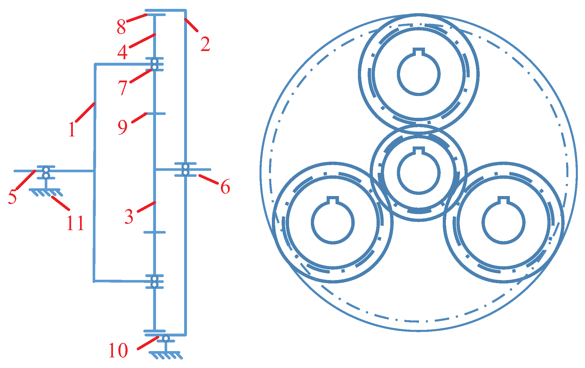
Figure 2.
Sketch map for the tooth breakage fault, (a) variation of the tooth profile; (b) variation of the contact line.
Figure 2.
Sketch map for the tooth breakage fault, (a) variation of the tooth profile; (b) variation of the contact line.
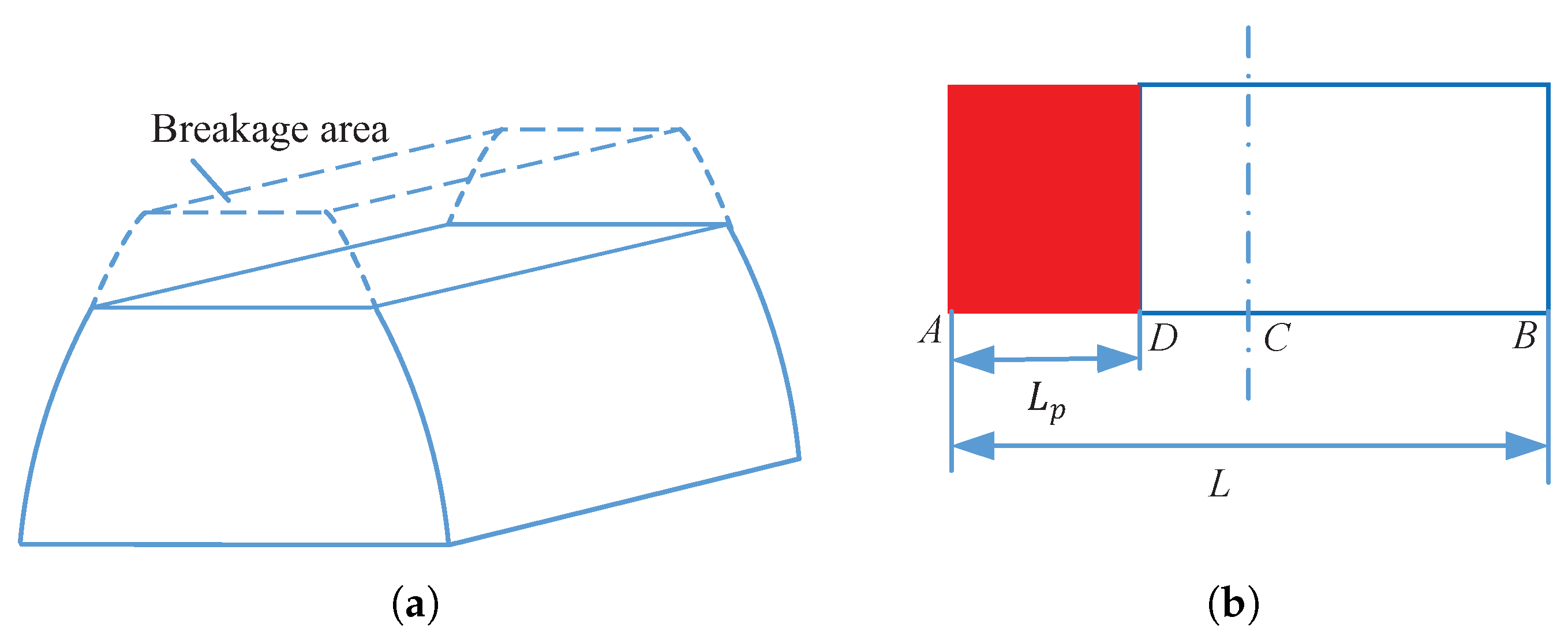
Figure 3.
The time-varying mesh stiffness in a planetary gear: (a) sun-first planet, (b) sun-second planet, (c) ring-first planet and (d) ring-second planet.
Figure 3.
The time-varying mesh stiffness in a planetary gear: (a) sun-first planet, (b) sun-second planet, (c) ring-first planet and (d) ring-second planet.

Figure 4.
The mesh stiffness of the sun-fault planet gear pair with different breakage sizes: (a) , (b) , (c) and (d) .
Figure 4.
The mesh stiffness of the sun-fault planet gear pair with different breakage sizes: (a) , (b) , (c) and (d) .

Figure 5.
Partial enlarged views of the mesh stiffness with different breakage sizes: (a) , (b) , (c) and (d) .
Figure 5.
Partial enlarged views of the mesh stiffness with different breakage sizes: (a) , (b) , (c) and (d) .

Figure 6.
The changes of root mean square (RMS) of the simulated ring vertical acceleration versus the (a) breakage size and (b) rotational speed.
Figure 6.
The changes of root mean square (RMS) of the simulated ring vertical acceleration versus the (a) breakage size and (b) rotational speed.

Figure 7.
Waveform of the simulated ring acceleration of the (a) healthy gear , (b) half tooth breakage fault gear and (c) the whole tooth breakage fault .
Figure 7.
Waveform of the simulated ring acceleration of the (a) healthy gear , (b) half tooth breakage fault gear and (c) the whole tooth breakage fault .
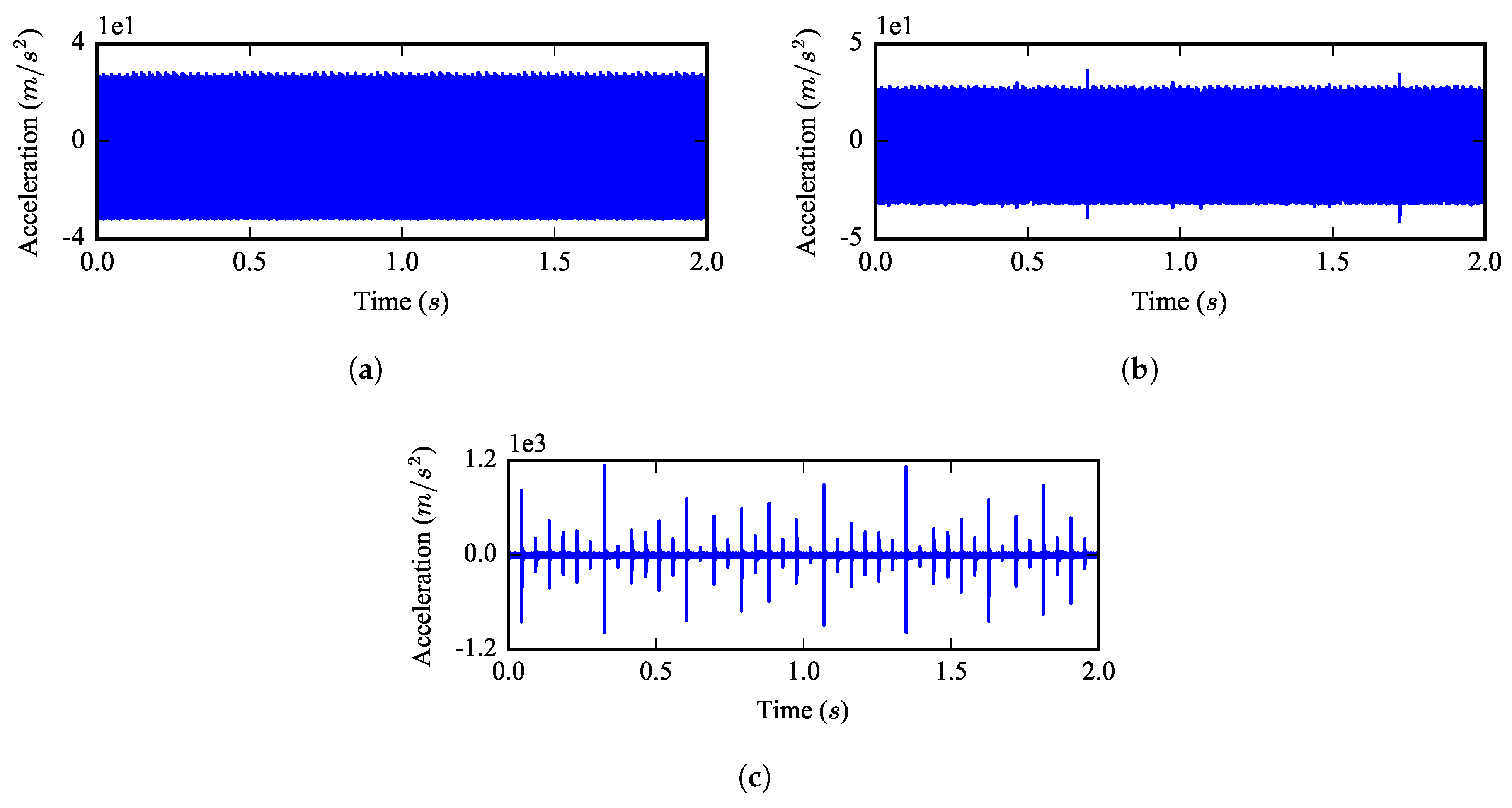
Figure 8.
Spectrum of the simulated ring acceleration of the (a) healthy gear , (b) half tooth breakage fault gear and (c) the whole tooth breakage fault .
Figure 8.
Spectrum of the simulated ring acceleration of the (a) healthy gear , (b) half tooth breakage fault gear and (c) the whole tooth breakage fault .
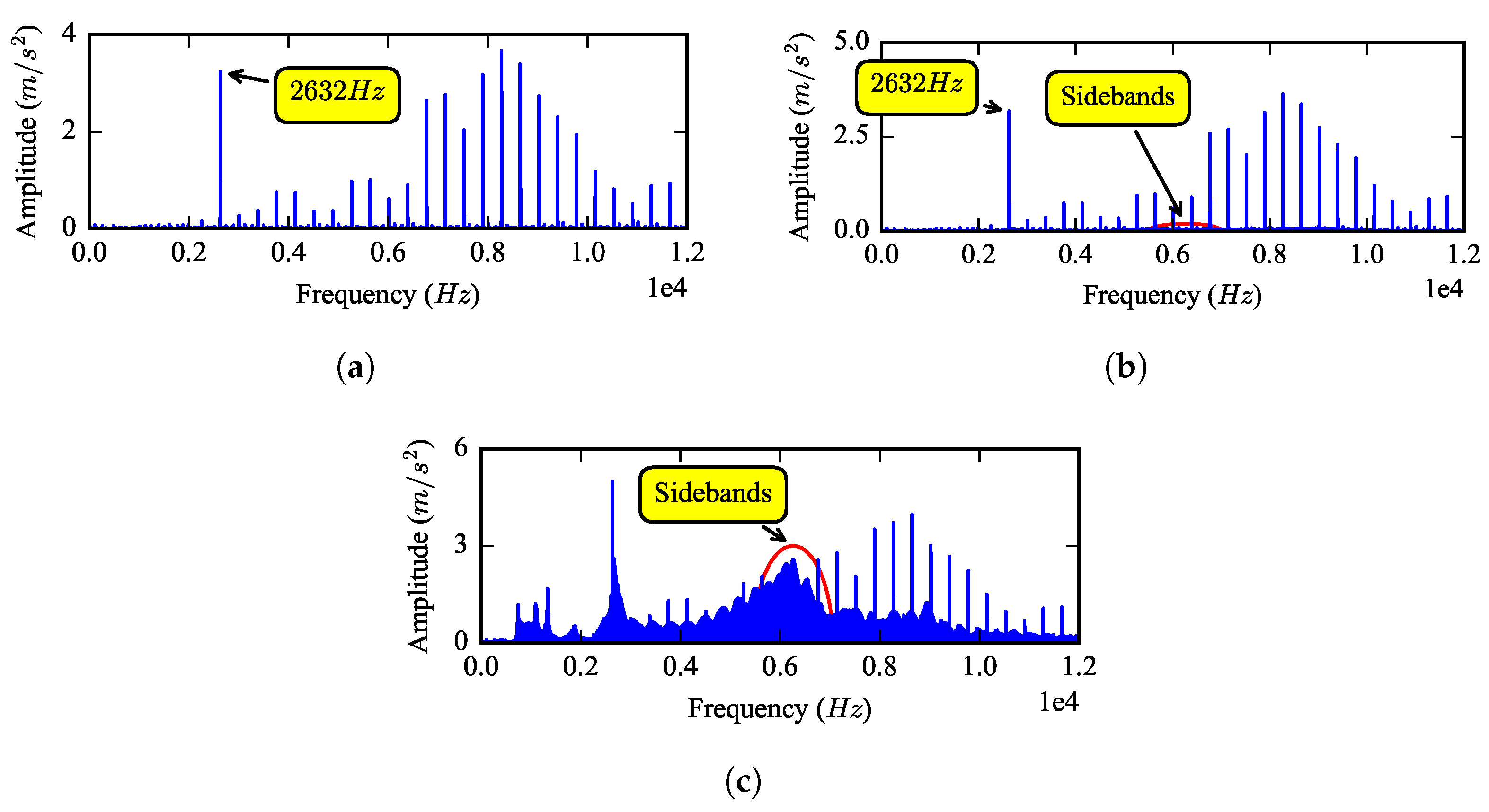
Figure 9.
Envelope spectrum of the simulated ring acceleration of the (a) healthy gear , (b) half tooth breakage fault gear and (c) the whole tooth breakage fault .
Figure 9.
Envelope spectrum of the simulated ring acceleration of the (a) healthy gear , (b) half tooth breakage fault gear and (c) the whole tooth breakage fault .

Figure 10.
Structure of the test rig: (a) structure diagram, where G is the gearbox, M is the motor, V is the variable frequency drive, P is the signal pre-processors, C is the collector, 1 to 7 are sensors, 1 is the rotational speed sensor and 6 is the gearbox vertical acceleration sensor; (b) picture of the test rig.

Figure 11.
Planet gears with: (a) half tooth breakage fault; (b) the whole tooth breakage fault.
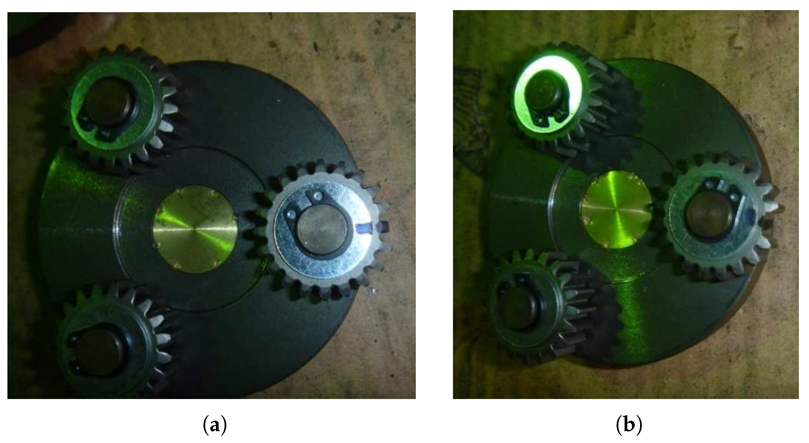
Figure 12.
RMS of the experimental ring vertical acceleration varying with rotational speed.
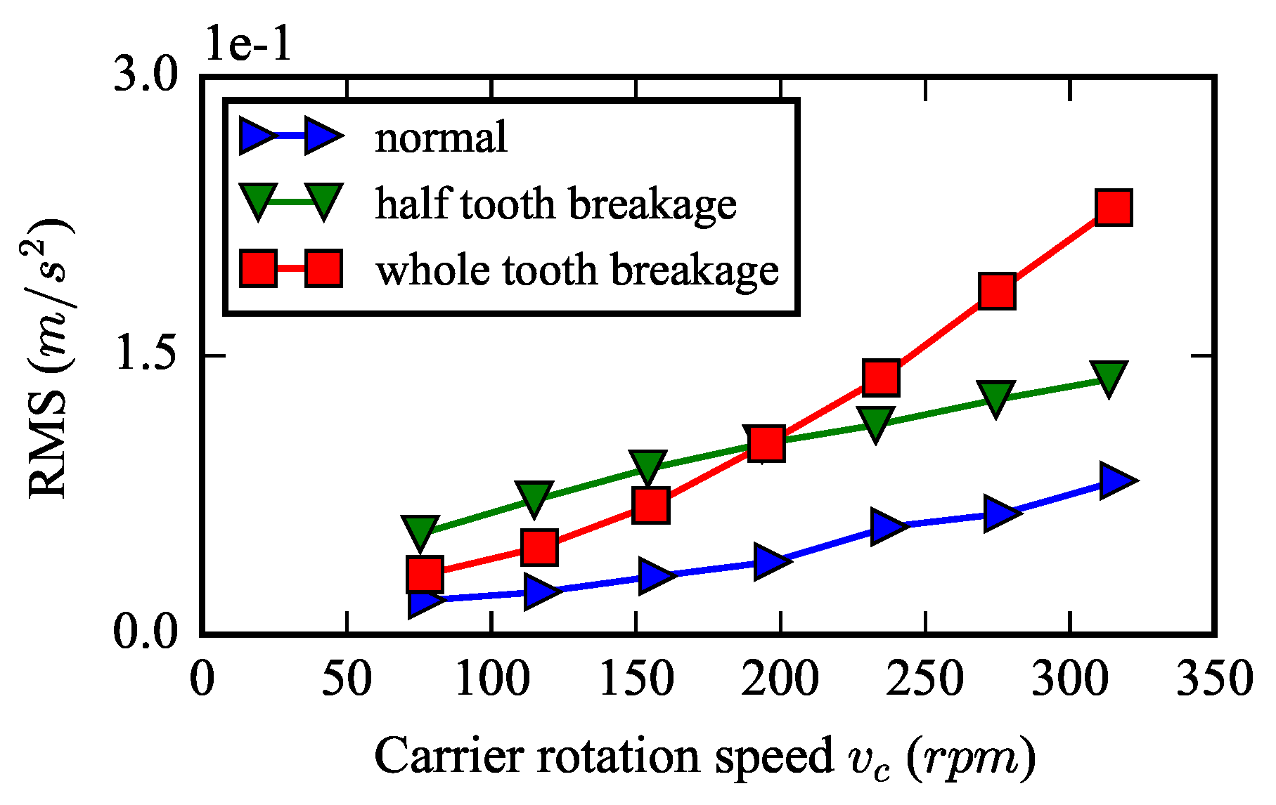
Figure 13.
Envelope spectrum of the experimental ring vertical acceleration of the (a) healthy gear, (b) half tooth breakage fault gear and (c) the whole tooth breakage fault.
Figure 13.
Envelope spectrum of the experimental ring vertical acceleration of the (a) healthy gear, (b) half tooth breakage fault gear and (c) the whole tooth breakage fault.
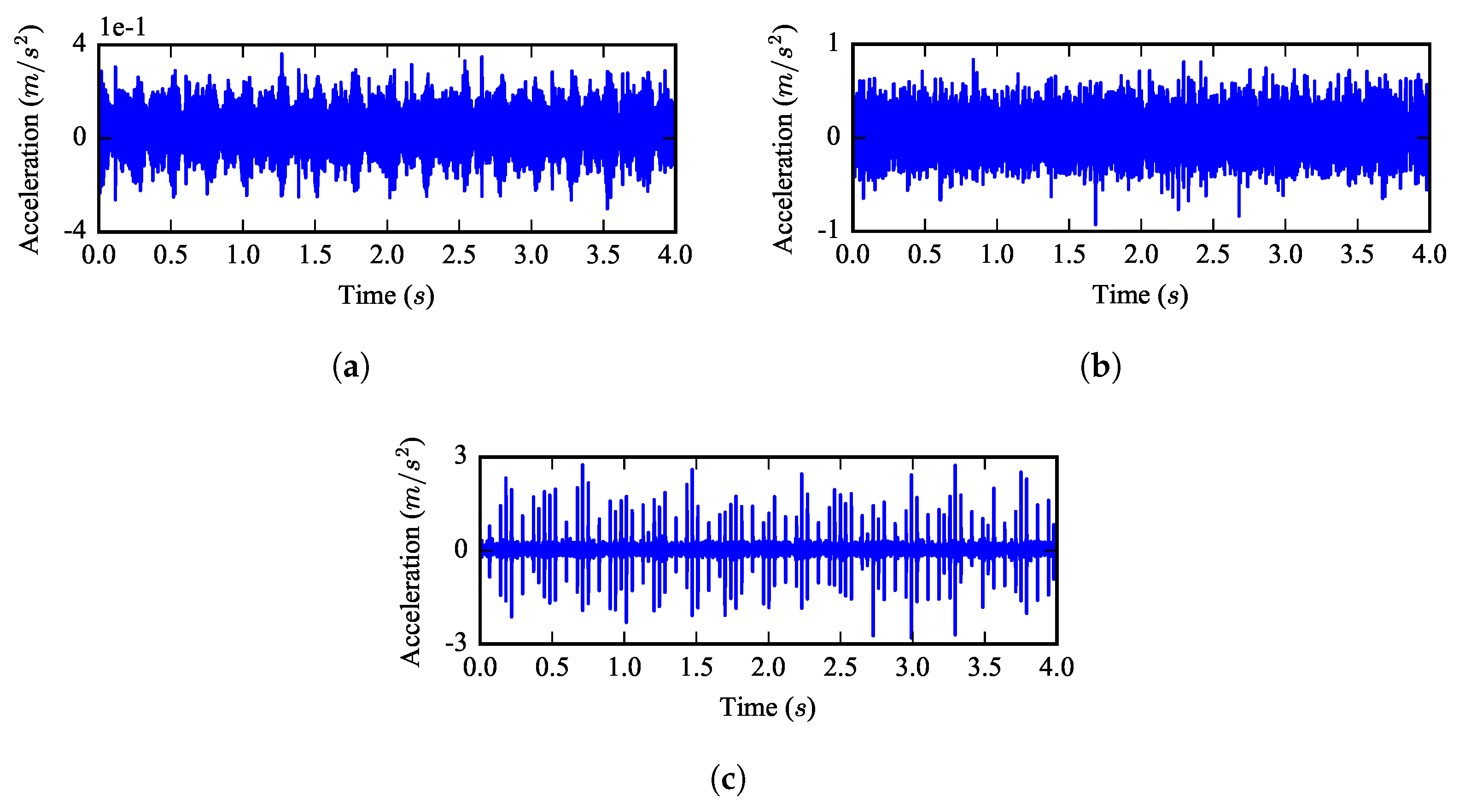
Figure 14.
Spectrum of the experimental ring vertical acceleration of the (a) healthy gear, (b) half tooth breakage fault gear and (c) the whole tooth breakage fault.
Figure 14.
Spectrum of the experimental ring vertical acceleration of the (a) healthy gear, (b) half tooth breakage fault gear and (c) the whole tooth breakage fault.

Figure 15.
Partial enlarged view of the experimental spectrum of the ring vertical acceleration of the (a) healthy gear, (b) half tooth breakage fault gear and (c) the whole tooth breakage fault.
Figure 15.
Partial enlarged view of the experimental spectrum of the ring vertical acceleration of the (a) healthy gear, (b) half tooth breakage fault gear and (c) the whole tooth breakage fault.

Figure 16.
Envelope spectrum of the experimental ring vertical acceleration of the (a) healthy gear, (b) half tooth breakage fault gear and (c) the whole tooth breakage fault.
Figure 16.
Envelope spectrum of the experimental ring vertical acceleration of the (a) healthy gear, (b) half tooth breakage fault gear and (c) the whole tooth breakage fault.


Table 1.
Parameters of the planetary gear for simulation.
| Parameter | Carrier | Ring | Sun | Planet |
|---|---|---|---|---|
| Teeth number | - | 96 | 27 | 35 |
| Mass (kg) | 5.43 | 2.35 | 0.4 | 0.66 |
| Inertia ( kg) | 59.1 | 56.7 | 0.58 | 1.53 |
| Base diameter (mm) | 96.9 | 137.5 | 38.7 | 50.2 |
| Mean mesh stiffness (N/m) | ||||
| Bearing stiffness (N/m) | ||||
| Torsional stiffness (Nm/rad) | ; | |||
| Pressure angle () | 24.6 | |||
| Helical angle () | 0 | |||
| Contact ratio | 1.24 | |||
| Planet number | 3 | |||
Table 2.
Natural frequencies of the planetary gear.
| Number | Rotational (Hz) | Translational (Hz) |
|---|---|---|
| 1 | 0 | 743.2 |
| 2 | 1334.0 | 1102.7 |
| 3 | 1891.3 | 1896.5 |
| 4 | 2662.8 | 2276.5 |
| 5 | 8045.4 | 6989.0 |
| 6 | 11,822.3 | 9651.7 |
Table 3.
Simulated rotational speed conditions.
| No. | C (rpm) | (rpm) | (Hz) | (Hz) | (Hz) | (Hz) |
|---|---|---|---|---|---|---|
| 1 | 77 | 76.4 | 1.27 | 5.80 | 122.2 | 3.5 |
| 2 | 117 | 116.1 | 1.93 | 8.81 | 185.7 | 5.3 |
| 3 | 157 | 155.7 | 2.60 | 11.8 | 249.17 | 7.12 |
| 4 | 197 | 195.4 | 3.26 | 14.8 | 312.7 | 8.93 |
| 5 | 237 | 135.1 | 3.92 | 17.9 | 376.1 | 10.8 |
| 6 | 277 | 274.8 | 4.58 | 20.9 | 439.6 | 12.6 |
| 7 | 317 | 314.4 | 5.24 | 23.9 | 503.1 | 14.4 |
Table 4.
Parameters of the planetary gear.
| No. | C (rpm) | (Hz) | (Hz) | (Hz) | (Hz) |
|---|---|---|---|---|---|
| 1 | 77 | 1.28 | 4.59 | 85.98 | 4.3 |
| 2 | 117 | 1.95 | 6.98 | 130.7 | 6.53 |
| 3 | 157 | 2.62 | 9.36 | 175.3 | 8.77 |
| 4 | 197 | 3.28 | 11.7 | 220.0 | 11.0 |
| 5 | 237 | 3.95 | 14.1 | 264.7 | 13.2 |
| 6 | 277 | 4.62 | 16.5 | 309.3 | 15.5 |
| 7 | 317 | 5.28 | 18.9 | 354.0 | 17.7 |
© 2017 by the authors. Licensee MDPI, Basel, Switzerland. This article is an open access article distributed under the terms and conditions of the Creative Commons Attribution (CC BY) license (http://creativecommons.org/licenses/by/4.0/).
Share and Cite
MDPI and ACS Style
Yang, W.; Jiang, D.; Han, T. Effects of Tooth Breakage Size and Rotational Speed on the Vibration Response of a Planetary Gearbox. Appl. Sci. 2017, 7, 678. https://doi.org/10.3390/app7070678
AMA Style
Yang W, Jiang D, Han T. Effects of Tooth Breakage Size and Rotational Speed on the Vibration Response of a Planetary Gearbox. Applied Sciences. 2017; 7(7):678. https://doi.org/10.3390/app7070678
Chicago/Turabian StyleYang, Wenguang, Dongxiang Jiang, and Te Han. 2017. "Effects of Tooth Breakage Size and Rotational Speed on the Vibration Response of a Planetary Gearbox" Applied Sciences 7, no. 7: 678. https://doi.org/10.3390/app7070678
Note that from the first issue of 2016, this journal uses article numbers instead of page numbers. See further details here.