A 3D Human Skeletonization Algorithm for a Single Monocular Camera Based on Spatial–Temporal Discrete Shadow Integration

School of Aerospace Science and Technology, Xidian University, No. 2 Taibai Rd, Xi'an 710071, China
*
Author to whom correspondence should be addressed.
Appl. Sci. 2017, 7(7), 685; https://doi.org/10.3390/app7070685
Submission received: 8 May 2017
/
Revised: 27 June 2017
/
Accepted: 29 June 2017
/
Published: 3 July 2017
Abstract
:Three-dimensional (3D) human skeleton extraction is a powerful tool for activity acquirement and analyses, spawning a variety of applications on somatosensory control, virtual reality and many prospering fields. However, the 3D human skeletonization relies heavily on RGB-Depth (RGB-D) cameras, expensive wearable sensors and specific lightening conditions, resulting in great limitation of its outdoor applications. This paper presents a novel 3D human skeleton extraction method designed for the monocular camera large scale outdoor scenarios. The proposed algorithm aggregates spatial–temporal discrete joint positions extracted from human shadow on the ground. Firstly, the projected silhouette information is recovered from human shadow on the ground for each frame, followed by the extraction of two-dimensional (2D) joint projected positions. Then extracted 2D joint positions are categorized into different sets according to activity silhouette categories. Finally, spatial–temporal integration of same-category 2D joint positions is carried out to generate 3D human skeletons. The proposed method proves accurate and efficient in outdoor human skeletonization application based on several comparisons with the traditional RGB-D method. Finally, the application of the proposed method to RGB-D skeletonization enhancement is discussed.
1. Introduction
The development of three-dimensional (3D) human skeleton extraction contributes enormously to prospering fields like virtual reality and somatosensory human–computer interaction. However, current 3D human skeletonization algorithms require specified acquisition equipments including RGB-Depth (RGB-D) cameras and wearable sensors, or a specific experimental setup like ring illuminator array. RGB-D cameras like Microsoft Kinect are designed to perform human skeletonization in a short range [1,2]. Wearable sensors only perform effective skeletonization on human subjects wearing experimental tags. Ring illuminator array requires precise subject position and illuminator array setup during the 3D modelling and skeletonization procedures. These setup restrictions of traditional human skeletonization methods bring great limitation on the outdoor applications.
Instead of deploying algorithms on traditional specified platforms, this work pays attention to the commonest projection of the human body on the ground. Shadow is the projection of a opaque object on a certain surface, containing single-view silhouette information of the object. Multiple methods have been developed to extract information from shadow. Current methods mainly focus on the recovery of mesh model [3,4,5] or point clouds [6,7] of static objects based on partial shadow information [8]. In this paper, a silhouetted shadow-based skeleton extraction (SSSE) method is proposed. The proposed SSSE method deploys shadow information extraction algorithm to the field of human skeletonization [9,10,11]. Based on the proposed SSSE method, six 3D joint positions in the human skeleton can be precisely extracted in outdoor scenarios with a normal monocular camera. Compared with current indoor 3D human skeleton extraction methods based on RGB-D cameras like Kinect, the proposed SSSE method reduces constraints on input device choice and application environment setup.
This work is motivated by the procedure of taking a silhouette photo. During this procedure, the human body blocks a part of light from reaching film or sensor, leaving a body sketch on the silhouette photo. Human shadow on the ground, from the aspect of silhouette imaging, can be regarded as a silhouette photo of the human body on a special giant film. The ground surface plays the role of film. For captured frames containing human shadows, each shadow on the ground can provide extra human contour information from a unique observation angle view other than the camera view.
This paper mainly focuses on the extraction and aggregation of the extra silhouette information from spatial–temporal discrete human shadows on the ground, aiming to perform 3D human skeletonization with a monocular camera in outdoor scenarios. Based on the aggregation of multiple shadows from discrete spatial–temporal coordinates, SSSE is capable of launching 3D human skeletonization even in outdoor scenes where the scale is too large for traditional methods [12,13,14] to handle [6,15,16]. The main contributions of this paper are related to three aspects:
- (1)
- The 3D human skeletonization is realized with a normal monocular camera based on the proposed SSSE method.
- (2)
- The proposed SSSE method achieves 3D human skeletonization in a large-scale outdoor scene.
- (3)
- The proposed SSSE method deploys the aggregation of temporal–spatial discrete two-dimensional (2D) shadow information in a 3D human skeletonization procedure
The remaining sections of this paper are organized as follows: In Section 2, the basic theory for shadow-based single frame human skeletonization is introduced first, followed by the advanced SSSE method aggregating temporal–spatial discrete shadow information to recover complete skeleton sequences. In Section 3, a five-step method is introduced to deploy the proposed SSSE method in large-scale outdoor scenarios with a monocular camera. In Section 4, the effective range and precision of the SSSE skeletonization results are evaluated in comparison with the skeletonization result of traditional RGB-D method. Additionally, a fusion application of the SSSE and RGB-D skeletonization method is achieved in Section 5, providing much wider effective range in outdoor scenarios. Eventually, the advantages and potential applications of the proposed SSSE method are illustrated in Section 6.
2. Basic Theory
This section presents the basic theory of the silhouetted shadow-based 3D human skeletonization method. To illustrate our method clearly, the basic theory under multiple light source scenarios is introduced first. Then the advanced theory designed to aggregate temporal–spatial discrete shadow information is introduced to achieve skeleton recovery under single light source scenarios.
2.1. Skeleton Simulation in Multi-Light-Source Scenarios
In a multiple light source scenario, contour of each human shadow on the ground is decided by two factors:
- (1)
- human contour shape.
- (2)
- positional relationship between the light source and the human.
Since each single shadow on the ground is restricted in a 2D plate, it is impossible to reproduce 3D information from any single shadow image. However, multiple shadows generated by different light sources can carry contour information from multiple 3D view angles, allowing the reproduction of 3D information.
A 3D voxel model of an object can be simulated from shadows generated by a annular set of light sources [6]. However, out of the laboratory environment, accurate manual arrangement of light source positions is elusive. Thus SSSE is designed to be adaptive to the posterior combination of random light source positions. With two or more shadows generated by different light sources, our method is capable of simulating 3D human skeleton information.
In a multiple light source scenario shown in Figure 1a, and are shadows of human body M, generated by light sources and respectively. The scenario is captured by camera C, and the human body M and shadows , are captured as P, , in the frame, respectively. With the captured frame, 3D position of the certain joint part can be extracted based on the following three steps.
2.1.1. 3D Scenario Reproduction
The silhouettes of human shadow are projected on the ground. To locate 2D shadow areas corresponding to different human joints, 3D scenario reproduction is launched to extract original 2D silhouette information from the corresponding images captured by camera C. The extraction is launched through the a two step perspective transformation between the ground surface plane and the camera coordinate plane . Due to the progressive road engineering and partial patching, the height levels between different road parts are normally discontinuous. Instead of deploying global perspective transformation between the ground surface plane and image coordinate plane , this work proposes a block matrix-based projection transformation optimized for uneven road surfaces.
Before the 3D scenario reproduction procedure, the projection transformation parameter matrices are calculated once. Then frame-by-frame block matrix-based projection transformations are launched to extract original silhouette information.
In order to illustrate the block matrix-based projection transformation clearly, traditional plane-to-plane projection transformation is presented first. Then the block matrix-based projection transformation is introduced along with the optimized extraction solution for parameter matrices. Based on the extracted parameter matrices, the simplified Equation (15) for frame-by-frame projection transformation is presented.
Plane-to-Plane Projection Transformation
During the imaging process of a monocular camera, the projection transformation from ground surface plane to image coordinate plane is carried out in two steps. Firstly, each point on ground surface plane is projected to corresponding coordinates on the camera coordinate plane. Secondly, a linear transformation happens inside the camera, transforming coordinates to pixel coordinates on the image coordinate plane.
The projection transformation between the point coordinates on the ground surface plane and the corresponding coordinates on the camera coordinate plane is presented as below:
is a fixed camera internal parameter that affects the linear transformation from the camera coordinate plane to the image coordinate plane. Noticeably, A is the projection transformation calibration matrix that defines the relationship between ground surface plane and camera coordinate plane. Multiple transformations are taken into consideration in architecting the projection transformation calibration matrix A.
- Rotation transformation. Most surveillance cameras are not precisely set up at the horizontal angle which is parallel with the ground surface. The non-horizontal installation attitude brings a rotated field of view. The rotation transformation is introduced to calibrate the rotated field of view, ensuring the calibrated field of view parallel with the ground surface.
- Scale transformation. The coordinate system of the ground surface plane is measured in centimeters. However, pixel is the basic unit of measurement in the image coordinate plane. Thus the scale transformation is introduced to bridge two different units of measurement, extracting ground surface plane coordinates from the pixel coordinates.
Both rotation transformation and scale transformation are linear transformations. The coordinates of both transformations are combined into the linear parameter matrix L.
- Translation transformation. For the image coordinate plane, the origin of the coordinate system is fixed at the bottom left corner. For each captured frame, the origin of the coordinate system on the ground surface plane does not necessarily coincide with the origin of image coordinate plane. The translation transformation is introduced to calibrate the translation between two coordinate systems. The detailed parameters for translation transformation are given in parameter matrix T.
- Perspective transformation. Instead of the flat view, a perspective view is captured by each monocular surveillance camera in each frame. Thus, the perspective transformation is introduced to recover the flat ground surface plane from the captured perspective view. The detailed perspective transformation parameters are given in parameter matrix P.
For linear transformation parameter matrix L, the scale transformation parameters and and rotation angle are included.
The translation transformation parameter matrix T is made up of translate values and in different axis directions.
The perspective transformation parameter matrix P is made up of perspective values and in different axis directions.
Based on the detailed transformation parameter matrices T, L and P, the projection transformation matrix A can be presented as:
Based on the Equations (1) and (5), coordinates , and on the camera coordinate plane can be presented by coordinates u, v on the ground surface plane and sub-parameters of matrix A.
Then, a linear transformation carried out to calculate pixel coordinates x and y in image coordinate plane. The transformation is controlled by the camera internal parameter .
Eventually, the pixel coordinates x and y can be presented by ground surface plane coordinates u, v and sub-parameters of projection transformation calibration matrix A.
Additionally, if the human shadow pixel coordinates x and y and projection calibration matrix A is acknowledged, the real-world coordinates u and v of the human shadow can be extracted based on solving the Equations (8a) and (8b). The procedure of solving real-world coordinates u and v is simplified in Equation (9).
Block Matrix-Based Projection Transformation Parameter Calculation
The traditional plane-to-plane projection transformation is designed for ideal scenarios with continuous flat ground surface. Nevertheless, the realistic scenarios contain uneven ground surfaces with discontinuous pavement levels. Thus, the single projection transformation calibration matrix A is not capable of ensuring precise projection transformation for all sub-blocks of the uneven ground surface.
In order to deploy the projection transformation on realistic scenarios with high precision, a block matrix-based projection transformation is proposed in this part. Instead of deploying imprecise plane-to-plane global transformation, the proposed method launches a set of precise sub-transformations. Each single sub-transformation covers only one partially flat sub-block on the ground surface, ensuring the precise projection transformation between a surface sub-block and the corresponding image subset. For each sub-block, the unique projection transformation calibration matrix is non identical with the parameter matrices belonging to other sub-blocks.
The parameter matrices of different sub-blocks are calculated separately based on Equations (8a) and (8b). To solve the unique calibration matrix of each sub-block, four pairs of marked point coordinates on ground surface plane and their corresponding pixel coordinates on image coordinate plane are required. However, manipulating massive markers to calculate parameter matrices of all sub-blocks will bring a heavy workload.
In order to simplify the setup, the optimized block matrix based parameter calculation procedure is designed to be marker coordinates multiplexable and parallel computing friendly. From the top-view angle, the ground surface is divided into a matrix consisting of multiple intensive square sub-blocks as shown in Figure 1b.
Each sub-block is a unit square area defined by the four corner markers, occupying one meter square area on the ground surface as shown in Figure 1b. The coordinate set of four markers on ground surface is defined as , their corresponding image coordinate set is .
For each sub-block , a set of auxiliaries is introduced to simplify the calculation of parameter matrices based on Equation (10). The scale auxiliary parameters set includes , , , and .
Additionally, the parallel auxiliary parameters and are introduced as Equation (10) as well. If both auxiliary parameters and approach zero, the field of camera view is regarded as parallel with the sub-block.
The translation parameter , perspective parameter and linear parameter in each calibration matrix can be solved as:
The extraction procedure of the block matrix based projection transformation calibration matrix can be simplified as:
Block-Matrix Based Projection Transformation Deployment
Based on Equation (9) and the calculated parameters in matrix , real-world coordinates of each point in one sub-block area can be calculated from the corresponding pixel coordinates . The presentation of extraction procedure can be simplified as:
Noticeably, different from the original global calibration matrix A, each sub-block calibration matrix is only deployed on the restricted regional transformation between the sub-block area on the ground and the corresponding pixel range in the image.
Once all parameter matrices for different sub-blocks are extracted through the block matrix-based parameter calculation procedure, coordinates of pixels belonging to different sub-blocks can be transformed to corresponding real-world coordinates inside the sub-block . Block matrix-based projection transformation is deployed based on the parallel computation of sub-transformations illustrated in Equation (13). The deployment algorithm of a sub-transformation is illustrated in Algorithm 1.
| Algorithm 1: Block matrix based projection transformation deployment Algorithm |
| Input: : coordinates set of marker positions for sub-block ; : corresponding pixel coordinates set of on image coordinate plane ; : image coordinates of captured pixel in human shadow silhouette Output: : corresponding real-world coordinates of  |
For each sub-block area , a distinctive sub-transformation thread is launched based on the specific calibration matrix . The parallel computation of block matrix-based projection transformation contains multiple sub-transformation threads. For the simplicity of the parallel computation presentation, is introduced as the collection of all calibration sub-matrices for different sub-blocks. The overall transformation is simplified as Equation (14).
Based on Equation (14), the real-world coordinates of human shadow silhouette can be extracted from corresponding pixel coordinates captured by a monocular camera. The block matrix-based projection transformation between the captured human shadow silhouette and the corresponding real-world shadow silhouette is illustrated in Equation (15).
The benefits of the block matrix based projection transformation are obvious:
- The positions of markers can be reused to simplify the scenario set up. For a scenario containing a square meter area, the number of markers is reduced from to .
- Parallel sub-transformations on different sub-blocks can be processed synchronously to accelerate the overall projection transformation procedure.
- Only when the position of camera is moved or the ground surfaced is repaved, will partial recalibration work be necessary for the affected sub-block .
Overall, all parameter matrices for different sub-blocks only need to be calculated once. Then all pixel coordinates in video frames can be transformed into the real-world coordinates on the ground surface plane. The block matrix-based structure also simplifies the parameter maintenance procedure when changes occur in the scenario.
2.1.2. Silhouette Information Extraction
For the extracted human shadow contour on the ground surface, joint positions are extracted through an optimized method based on the silhouette contour extreme point seeking method. Comparing with traditional human segmentation methods, only silhouette information is available for shadow contour segmentation in our work. In order to perform an efficient joint position extraction based on precise silhouette contour segmentation [17], a two-step algorithm is presented in this section.
Human Shadow Silhouette Contour Preprocess
Firstly, a survey for global peak points on the shadow contour is launched to locate most obvious joint positions on the human shadow contour. In this step, the gravity center coordinate of human shadow contour is calculated first. For human shadow contour containing N contour points , the gravity center can be extracted based on the Equation (16).
Then, the the distance curve D between contour points and the gravity center is calculated for the localization of global peak points. The value of each point on the distance curve D is calculated based on Equation (17). The Cartesian distance is applied in the Equation (17) as a linearized approximation for the value of each point on the distance curve.
In order to reduce the interference of grainy ground surface in the joint position extraction procedure, the distance curve D is denoised based on Equation (18). The smooth length unit is set as 10 in our experiment. In the next step, the localization procedure of major joint positions is based on the denoised distance curve .
The global peak points including head and two feet appear at the maximum point on the distance curve. Based on the denoised distance curve , the major joint positions can be located through seeking peak points. The normalized distance curve extraction procedure is illustrated from Equation (16) to Equation (18) and simplified in the stage Equation (19). In order to simplify the subsequent presentations, function is introduced to cover the extraction procedure for the normalized distance curve based on the human shadow contour .
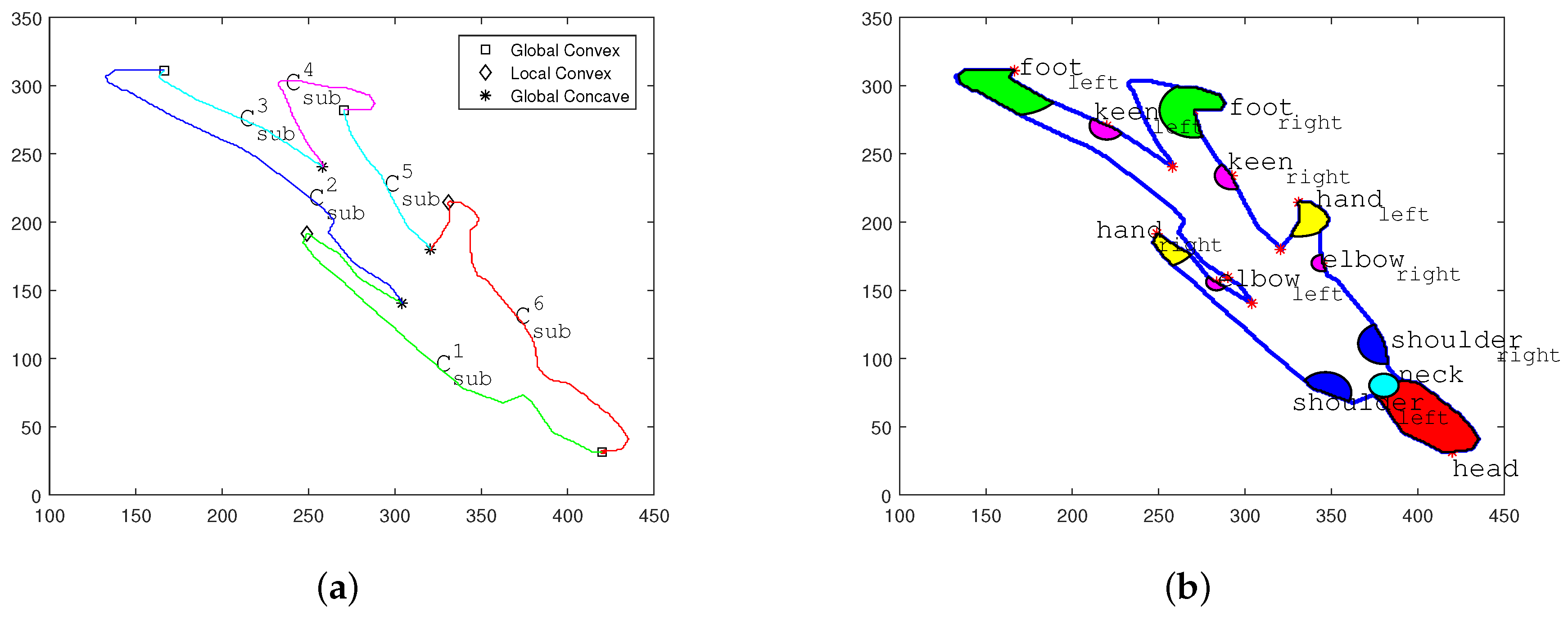
Localization of Major Joint Positions on Human Shadow Silhouette Contour
In the second step, a quick localization of global maximum peaks is launched first to locate the positions of head and both feet, then elaborate local search for major joints including hands, shoulders and knees is carried out.
- (1)
- Localization of Global Convex Areas
Three global maximum peaks of denoised curve is marked in corresponding positions on Figure 2a with square symbols. The marked positions indicate precise global convex area on the human shadow silhouette contour, including head , left foot and right foot . As shown in Figure 2b, the area containing the head are marked in red, and areas containing the feet are marked in green.
- (2)
- Localization of Auxiliary Anchor Points
Based on the acknowledged major joint positions including head and feet, the positions of rest joints are calculated through locating the local peak and nadir points.
Based on the three major joint positions, the shadow contour is divided into three sub-curves. Each sub-curve contains one auxiliary anchor point at the corresponding local nadir position on curve . The auxiliary anchor points are markered with star symbols in Figure 2a.
- The sub-curve between two feet joints contains the position of hip center at the local nadir position.
- The sub-curves between the head position and two feet positions contain positions of two oxters at local nadir positions, respectively.
- (3)
- Localization of Remaining Major Joint Positions
Based on the three global peaks and three auxiliary anchor points, the shadow contour is subdivided into six new sub-curves. To illustrate the extraction of remaining joint positions clearly, six sub-curves are marked as . The indicated i ranges from 1 to 6 as shown in Figure 2a. to cover the shadow contour in a clockwise direction , initiating from the head position.
- Sub-curves and cover the contour ranges of left arm and right arm. Thus the local peak positions of these two sub-curves are hand positions. Their local nadir positions are located between the cervical vertebra position and two shoulders.
- The local peak positions of and indicate the positions of two keens and in the shadow area.
- Similarly, the nadir positions of and can assist the positioning of both keens and .
The major joint position localization procedure is illustrated in the three steps above and simplified in stage Equation (20). In order to simplify the subsequent presentations, function is introduced to cover the localization procedure for major joint position set based on the human shadow contour and the corresponding distance curve .
Noticeably, the joint position localization procedure can also be adopted in the joint position extraction from a normal human pose contour. The human pose classification illustrated in Section 2.2.2 is based on the joint position extraction procedure illustrated in Equation (20).
2.1.3. 3D Joint Position Estimation and Skeleton Synthesis
In a multiple light source scenario, more than one human shadow is projected on the ground surface at the same time. In order to identify shadow areas generated by different light sources, 2D human shadow contour and joint position region are footnoted with corresponding light source identifier i as shown in Equation (21). Additionally, the point coordinates inside the each region are footnoted as .
In order to estimate the 3D joint position of each major joint, the light beams from different light sources blocked by are reconstructed first. Then, the 3D position of is calculated based on allocating the shared voxel area between multiple reconstructed light beams . Finally, the human skeleton is synthesized based on the calculated 3D joint position set .
For the first step, each light beam is generated as a 3D cone with its vertex on the light source position . The underside of each cone is the joint area in the shadow.
While any light beam from light source is blocked by the certain joint part of human body M, the joint shadow area is produced on the ground. Thus, the direction of blocked light beam leads to shadow area , going through human body part . If is introduced as the height component in the cone expression of , the 3D space caused by can be presented as Equation (22).
The 3D light beam shape extraction procedure presented by Section 2.1.3 is simplified in the stage Equation (23). For the simplicity of the subsequent presentations, function is introduced to cover the 3D light beam shape extraction procedure for the occupied 3D cone shape based on the corresponding joint position and the light source position .
Then, for multiple light beams generated by different light sources , is the shared subset for all reconstructed . Thus, the 3D position can be generated based on the intersection of all reconstructed as shown in Figure 3a. is the sum of light sources in the scenario.
Figure 3a demonstrates the recovery of neck joint area based on two related shadow areas and generated by light sources and .
Finally, 3D human skeleton with multiple joint positions is synthesized by calculating joint by joint.
Figure 3b presents the skeleton synthesis procedure of a human being based on human shadow information under a multi light source scenario. The illustrated human skeleton synthesis procedure is presented in Algorithm 2 and simplified in Equation (25).
However, there are two restrictions for the deployment of the basic theory:
- Condition (1) Two or more light sources are required in the scene.
- Condition (2) Relative angular positions between human body and different light sources should be different.
| Algorithm 2: Human skeleton synthesis procedure under multiple light source scenario |
| Input: : 2D human shadow contour on the ground surface. : 3D positions of multiple light sources . Output: : 3D human skeleton synthesis based on seven major joint positions.  |
2.2. Skeleton Simulation in Single-Light-Source Scenario
The basic theory introduced in Section 2.1 is only effective in scenes containing two or more shadows generated by multiple light sources. For single light source scenarios, only one shadow is generated in each captured frame. In order to extend the proposed basic theory in single light source scenarios, a video sequence instead of a single frame is taken into consideration. Human shadow contours are footnoted with time coordinate t in this part. The extension solution is introduced below.
2.2.1. Theoretic Proof of the Extension Solution in a Single Light Source Scenario
For every video sequence, the extension solution is based on two facts:
Temporal Distinguished Relative Position between Light Source and Human Body
In a sequence, the relative position between a moving human and a fixed light source keeps changing. In other words, temporal discrete shadows are generated by the light sources from different relative positions towards the human. The temporal neighboring human shadows and are distinguished from each other because of different relative positions between the light source S and the human body. For neighboring frames at time coordinates t and , it is clear that and .
Temporal Discrete Shadows for Same Human Pose
In order to categorize different frames based on the human poses, the 2D contour of human body captured by a monocular camera is regarded as the human pose at the time coordinate t. As shown in Figure 4b, same human pose appears repeatedly during an activity sequence. Since each relative position between the light source and human body is different frame by frame, multiple frames sharing the same human pose can be found. Each frame owns different shadows and projection angles . In an activity sequence, all the human shadows sharing the same human pose are categorized into the set . For different human shadows , their corresponding relative position angles are distinguished from each other. If multiple human shadows in with different projection angles are integrated in one single frame as shown in Figure 4b, condition (2) of launching the basic theory proposed in Section 2.1 is satisfied. Through applying translation transformations on each integrated frames to make the all human poses spatially coincide with the central pose , an artificial multiple light source scenario satisfying conditions (1) and (2) is established as shown in Figure 4c.
The simulated scenario makes it feasible to recover the skeleton of the shared pose in a single light source scenario based on the basic theory proposed in Section 2.1.
2.2.2. Temporal–Spatial Aggregation Method
Before the deployment of human skeletonization, it is necessary to find shadows that share the same human pose , yet have distinctive projection angles . Human pose classification and temporal–spatial shadow aggregation are deployed to fit spatial coordinates of shadows in with the chosen central pose position .
Human Pose Classification
In order to analyses the human pose at each time coordinate , the denoised distance curve between the human pose contour and human pose gravity center is extracted based on the same method illustrated in Equation (19). Similarly, the stage Equation (26) covers the normalized distance curve extraction procedure illustrated from Equation (16) to Equation (18). The function presents the extraction procedure for the normalized distance curve based on the contour curve .
Based on the distance curve , major peak point set including head and two feet are extracted from the captured human contour based on the same procedure presented in Equation (20). Similar to the stage Equation (20), stage Equation (27) covers the major joint position localization procedure illustrated in the Section 2.1.2. The function presents the human joint position extraction procedure for major joint position set based on the human contour and the corresponding distance curve .
The positions of three peak points of the human pose contour are combined into a star feature to describe the human pose in each frame [10,18]. Then unsupervised classification is adopted to assort each frame with corresponding pose category label based on the star feature [19].
Temporal–Spatial Shadow Aggregation
During the temporal-spatial shadow aggregation procedure shown in Figure 4c, temporal discrete light sources are aggregated in a single frame. Normally, for multiple human poses, the human pose with median time coordinate is chosen as the central pose .
For each human pose , the translation transformation parameter is defined by the vector between corresponding joint points in and , satisfying the spatial transformation from to .
Noticeably, the joint positions and are captured in the image coordinate plane. Before calculating the translation transformation in real-world coordinates, it is necessary to transform the joint coordinates into the real- world coordinates and based on the stage projection transformation presented in Equation (14).
As shown in Equation (29a), is the extracted real-world human joint coordinates at the original captured position. In Equation (29b), is the human joint coordinates at the destination position. Then the translation vector is calculated based on the averaged horizontal translation vectors from the original position to the destination position. As shown in Equation (29c), and are two vertical unit vectors of the real-world coordinate system on the ground surface. The translation vector is presented as a combination of translation components and in two vertical directions. Based on the translation components and , a translation transformation matrix can be established for the translation calculation as shown in Equation (29d).
For the convenience of further illustration, the extraction procedure of matrix is simplified in Equation (30). The function is introduced to present translation matrix extraction procedure illustrated from Equation (29a) to Equation (29d).
In order to maintain a consistent expression system, the translation transformation is presented in the same format with Equations (14) and (15). When the translation transformation in Equations (31) and (32) is deployed synchronously on the light source and human shadow contour for each frame, all the transformed human shadows fit the spatial coordinates of the central human pose in each simulated scenario.
The position of light source applies the same transformation along with the related shadow , simulating multiple light sources in the single frame.
The temporal–spatial aggregation procedure illustrated above is presented in Algorithm 3. With more than two positional distinctive light sources simulated in the same frame, the skeleton synthesis procedure presented in Equation (24) can be applied on the simulated human shadow set and the corresponding light source set . Based on Equation (33), the skeleton of pose can be synthesized under a single light source scenario as shown in Figure 4d. The detailed human skeleton synthesis procedure under a single light source scenario is illustrated in Section 3.
| Algorithm 3: Temporal–spatial aggregation procedure |
| Input: : time coordinate for each frame; :human shadow on the ground surface in frame ; : human pose in frame ; S: light source position; : joint position set of the central pose on the aggregation destination; Output: : integrated human shadow in the simulated scenario. : integrated light source position in correspondence with .  |
3. Proposed Method
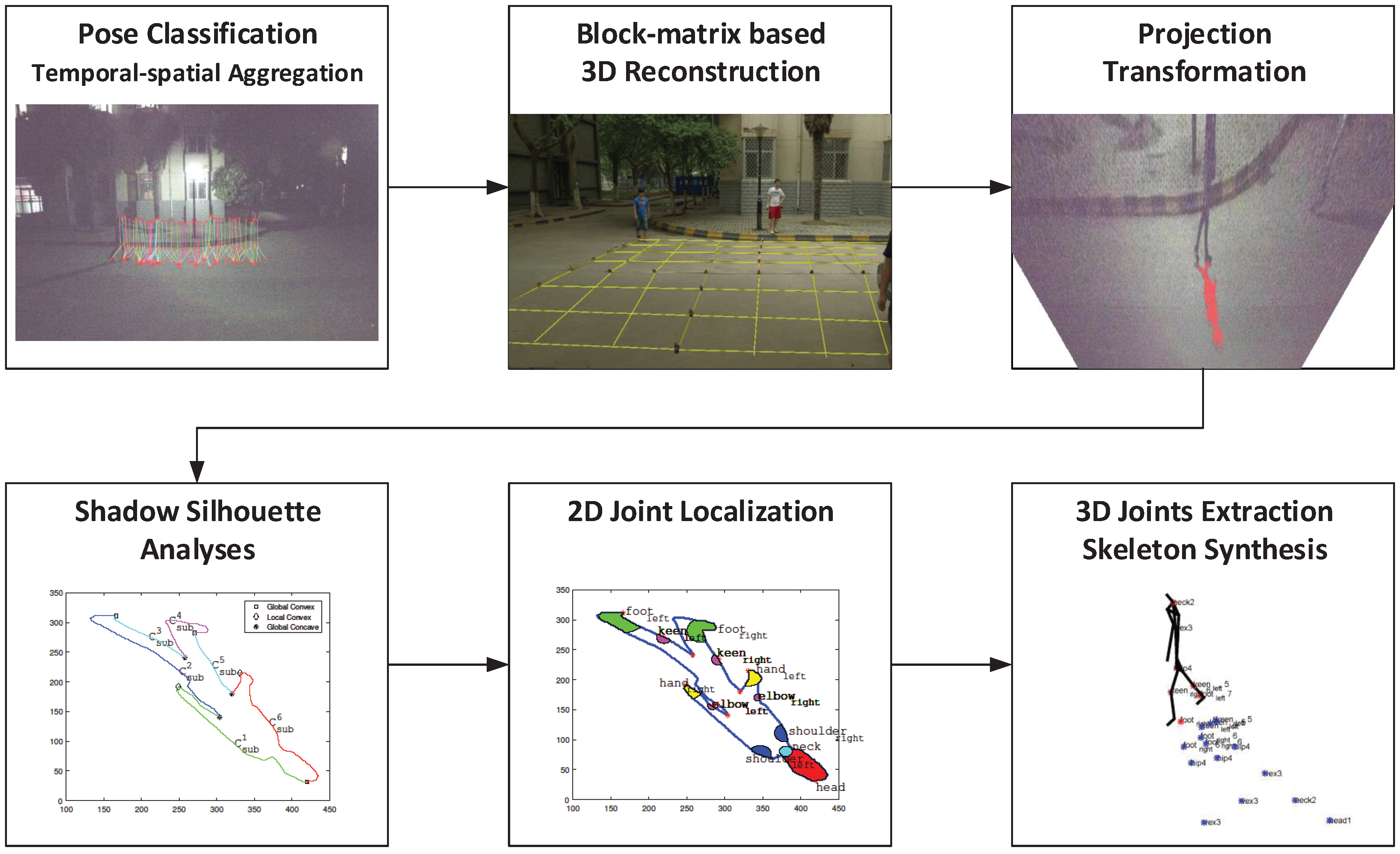
Based on the basic theory and its extension introduced in Section 2, a normal single light source scenario can support 3D human skeletonization. In this section, a five-step algorithm is proposed according to the illustrated theory as shown in Figure 5. The procedure of the proposed method is shown in Algorithm 4.
| Algorithm 4: Skeleton synthesis procedure |
| Input: : time coordinate for each frame; :captured human shadow in frame ; : human pose in frame ; S: light source position; : the set of sub-blocks on the ground surface plane S : the marker position coordinate sets for sub-block on S; : the pixel coordinates set of on the image coordinate plane. Output: : 3D human skeleton corresponding to at time coordinate  |
Pose Classification
In a human activity sequence captured under a single light source scenario, frames at different time coordinates are classified based on human poses [8] on the captured frames. For each captured human pose at time coordinate , the denoised distance curve between contour points and the gravity center of can be extracted based on the method presented in Equation (19). The deployment of the extraction method on the human pose is presented in Equation (34).
Based on the method presented in Equation (20), a major peak joint position set is extracted from the human contour , including the head position , the left foot position and right foot position .
Based on the normalized peak joint positions, raw frames containing same class human poses is aggregated to the human pose category based on the automatic unsupervised clustering illustrated in Equation (28). is the category label of human pose as shown in Equation (36).
Preprocess
The preprocess procedure transforms the captured shadow contour pixel coordinates into the real-world coordinates .
Before the preprocess of the first shadow contour , all the are calculated and saved for further preprocess procedures. For each square unit area , the related projection parameter matrices are calculated based on four real-world coordinates and their corresponding imaging coordinates based on Equation (12).
Based on the calibration matrix set , the global projection transformation can be figured out. Based on the projection transformation presented in Equation (37), captured human shadow contour pixel coordinates can be extracted from each of the raw frames and transformed into the real-world coordinates .
Temporal–Spatial Aggregation
Preprocessed shadow contours are aggregated according to category of corresponding human pose . Nevertheless, the real-world coordinates of are spatially dispersed due to the human movement as shown in Figure 4a. Thus it is necessary to aggregate shadow contours of the same central human pose to deploy precise joint position estimation.
For each pose category, one central human pose is set up as the aggregating destination for other human shadow related with .
The translation of each human shadow is based on the translation transformation calibration matrix . The translation transformation matrix is calculated based on the Equation (30). Since the major peak joint position sets and are obtained in the pose classification step, the translation transformation calibration matrix can be extracted as shown in Equation (38).
Along with the 2D translation of each , the corresponding 3D light source position is moved with the identical translation as shown in Equation (39b). The aggregated human shadow and light source offer the ideal multiple light source situation for 3D joint position estimation.
As shown in Figure 4b, when is setup as the aggregating destination, other are aggregated to the aggregating destination through the 2D translation as shown in Equation (39a).
Joint Position Estimation and Skeleton Synthesis
For each aggregated human shadow contour , joint area estimation is launched based on the algorithm introduced in the basic theory section. First of all, the gravity center of curve is calculated. Then, the denoised distance curve between each point and is available based on the preprocess procedure illustrated in Section 2.1.2.
The 2D positions of major joint areas including head , neck , hip center , left keen , right keen , left foot and right foot can be obtained through locating the peak and nadir points in .
In each simulated scenario, silhouette information extraction is applied to each joint area . In order to estimate the 3D joint position based on , the ray set connecting light source and joint shadow area is simulated.
Since more than two simulated light sources exist in the scenario, silhouette information of single joint area is extracted separately for each light sources. Based on all ray sets targeting at the same joint, 3D joint position can be calculated based on Equation (43).
Repeating steps above for each major joints, 3D joint position set containing all joint positions can be figured out. Then joint positions can be synthesized based on the combination Equation (44).
In order to simplify the presentation in Algorithm 4, the illustrated joint position estimation and skeleton synthesis procedure is simplified into Equation (45).
Frame Integration
Repeating the above steps, synthesized 3D human skeletons can be generated for all human poses category by category. The kinematic model of skeleton contains seven major joints, including head, neck, hip, both keens and both feet. The bones connecting particular joints are regarded as rigid objects. Based on the pose classification result in the step (1), the time coordinate of each can be tracked. Then, reassign synthesized human skeleton to frame as based on the reverse translation transformation.
4. Experimental Validation
In this section, the experimental data source and settings are illustrated first. Then the effective range and precision of the proposed method are validated in comparison with the RGB-D based method.
4.1. Data Source Description and Experimental Settings
The experiments are launched based on data captured by a Kinect RGB-D camera, containing daily human activities. Captured sequences include both RGB frames and normal depth frames captured by Kinect. Kinect extracts human skeleton automatically based on the combined information of RGB frames and depth frames [15]. However, SSSE is deployed only on RGB frames captured by the monocular RGB camera on Kinect.
In each sequence captured for effective range validation, Kinect is set up at a static distance from the human subject. The photographic distance increases from 1 m to 20 m with a fixed step of 1 m. Sampled skeletonization results based on both methods at different distances are presented in Figure 6a.
4.2. Effective Range and Precision Analyses
In order to validate the effectiveness of the proposed SSSE method and traditional RGB-D method, two aspects including effective range and precision are evaluated. In the following, the effective distance range is marked first. Then, the precision of six major 3D joint positions extracted by SSSE is evaluated.
Effective Range
Effective range is defined as the distance between the sensor and human, which allows effective human skeleton extraction. Effective human skeleton extraction in the effective range generates valid human joint positions. For the RGB-D based method, each extracted joint position comes with a confidence index. Valid joints are joints with confidence above 0.7. For the SSSE method, valid joints are extracted joints not affected by sheltering. In the following experiments, frames with all valid simulated human joints are defined as effective frames. In order to obtain the effectiveness–distance relationship of both methods, the shares of effective frames at different distance levels are measured. In addition, 1000 to 1200 frames containing 3D human skeletons sampled at each photographic distance from 1 to 20 m are evaluated for each method. For the RGB-D-based skeletonization procedure, effective frames are automatically labeled based on the corresponding joint confidence. For an SSSE-based procedure, effective frames are chosen based on the number of valid joints in each skeleton. The effectiveness of both methods at the same distance can be represented by the shares of effective frames among all frames. For each method, effective range covers photographic distances whose effectiveness exceed a specified threshold.
The official parameter of Kinect [1,15] indicates the effective range of state-of-art Kinect result is from 0.8 m to 3.5 m. Thus, the range of distance where effectiveness is above 0.8 is regarded as the effective range. As shown in Figure 6b, the effective range of SSSE is 7–10 m. Note that the effectiveness of SSSE decreases when photographic distance exceeds 10 m because of the limitation of camera resolution. The experimental result in Figure 6a shows that SSSE can provide reliable 3D human skeletonization at an effective range of 7–10 m, while Kinect is unable to extract human skeleton information when the photographic distance exceeds 5 m.
Precision Evaluation
As with the effectiveness evaluation result mentioned above, the RGB-D-based method and SSSE provide effective skeleton extraction results at different distance ranges. Precisions of all extracted joints by SSSE are determined by the deviation values relative to corresponding ground truth joint positions. In the precision evaluation procedure, two Kinects are setup for different purposes. Kinect No.1 is set up 9 m way from human object, capturing RGB frames for human skeletonization based on SSSE. Kinect No.2 is setup 3 m away from human object, capturing RGB-D frames along with 3D human skeletons simultaneously. Since 3 m is inside the effective range of the RGB-D-based 3D skleletonization, the 3D joint positions captured by Kinect No.2 are valid joints, providing ground truth for the deviation calculation. Based on the experimental scenario setup, 1546 frames are captured simultaneously for both methods, of which 1345 effective frames are evaluated.
For each skeleton extracted from a effective frame, joint positions are normalized relative to the hip center, avoiding deviation introduced by different shot distances.
Six major joints are considered in evaluation, including head, spine, both keens and both feet. Figure 7 depicts the averaged precision evaluation result.
As presented in Figure 7, due to the larger scale of upper body shadow on the ground, relative high deviations appear at joints of the head and spine, where averaged deviations reach 14.5 cm and 12.1 cm, respectively. For the remaining joints, the averaged deviations are around 4 cm and the highest deviation remains below 8 cm. In summary, SSSE extracts joint positions in a reasonable precision at 9 m away from the target human, compared with the ground truth Kinect skeletonization result obtained at a position 6 m closer to the subject human.
5. Discussion
Based on the experimental results in Section 4.2, an interesting phenomenon can be observed in that the effective ranges of the proposed SSSE and traditional RGB-D method are highly complementary. Thus, the fusion application of SSSE and traditional RGB-D method can provide wide range human skeletonization for indoor and outdoor scenarios. In the fusion method, the traditional RGB-D method and SSSE are deployed under different scenarios. For humans inside the effective range of RGB-D cameras, the traditional RGB-D based skeletonization method can provide solid human skeleton extraction method. For humans outside the effective range of RGB-D cameras, SSSE method can redress the unreliable 3D joint positions appears in RGB-D skeletonization result. In order to evaluate the fusion application effectiveness, a comparison between the reliable joint percentage of original skeletons extracted by Kinect and redressed skeletons processed by SSSE is carried out in this section. Reliable joints are defined as joints generated by SSSE not affected by sheltering, and joints generated by Kinect with a confidence index above 0.7. On the contrary, unreliable joints are unavailable joints affected by sheltering in SSSE methods, or joints generated by Kinect with confidence index under 0.7. For better evaluation of the fusion application, Kinect is set up to skeletonize a human subject outside its effective range.
The unreliable 3D joint positions in Kinect skeletonization result is redressed by SSSE simultaneously. In total, 20 sets of experiments have been launched to evaluate the reliable joint percentage enhancement.
5.1. Reliable Joint Percentage Enhancement
The enhancement of the reliable joint percentage is evaluated by determining the precisely recovered joint rate and precisely recovered frame rate . As shown in Equation (6a)–(6c), and are the unreliable joint number and relevant affected frame number, respectively. is the number of total recovered unreliable joint positions after deploying the SSSE procedure, while is the number of inaccurately recovered joints. From the aspect of frame statistics, is the total number of recovered frames and is the number of frames containing inaccurately recovered joints.
The 20 test sets presented in Table 1 indicate that more than four-fifths of all unreliable joints are successfully redressed based on the proposed SSSE method, and more than three-quarters of all frames containing unreliable joint skeletonization results are accurately fixed. Based on the experimental results above, the fusion application of SSSE and traditional RGB-D method proved effective in reliable joint percentage enhancement.
5.2. Computational Cost Evaluation
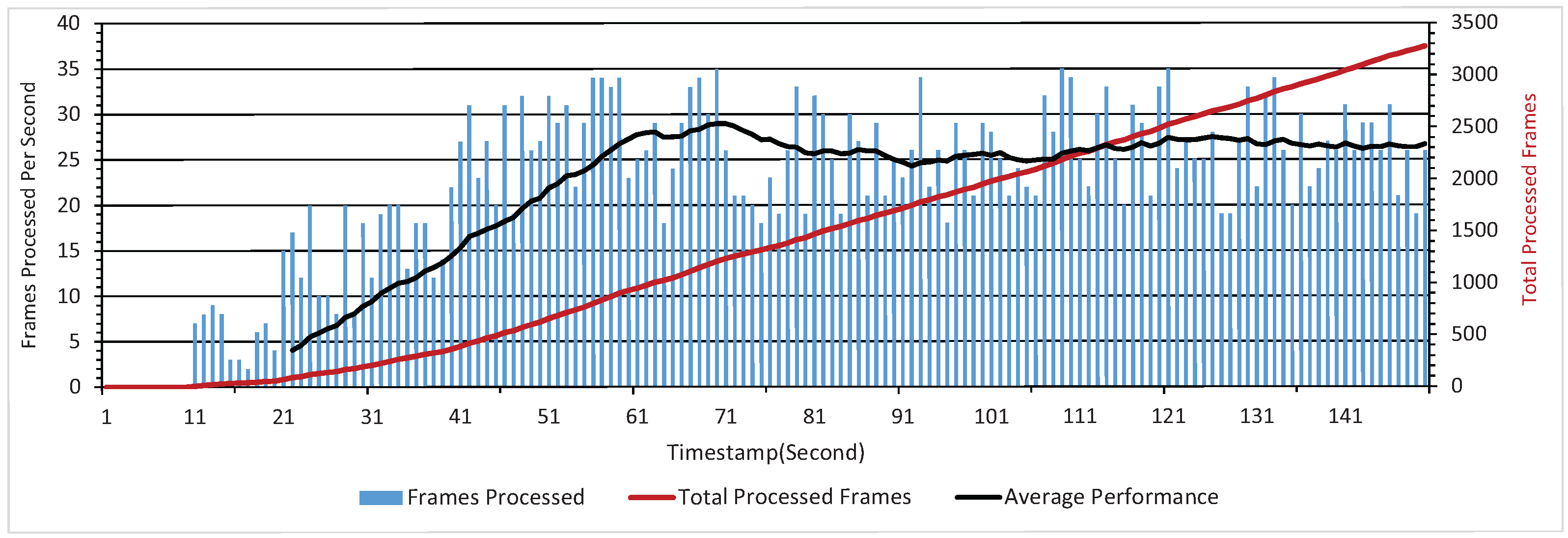
The simultaneous collaboration between the RGB-D skeletonization method and proposed SSSE method is crucial for the real-time deployment of the fusion application. Thus, limiting the computational cost is essential for the effectiveness of the fusion method. The test platform is a mainstream personal laptop connected with the first generation Kinect, equipped with one Intel Core i7 central processing unit (CPU) and 16 Gigabyte of random access memory (RAM). Two indicators, i.e., maximum process capability per second and single frame delay are concerned in order to evaluate the computational cost. This evaluation test aims to process as many frames as the computational capability allows based on the proposed method. The computation cost efficiency of the fusion application is determined by the number of frames processed per second. As shown in Figure 8, the stable maximum process capability remains around 25 frames per second after the initial stage where less than 10 frames are processed per second. The experimental result indicates that the fusion application is feasible for real-time deployment based on its stable maximum process capability.
6. Conclusions
In this paper, we proposed a shadow silhouette-based skeleton extraction (SSSE) method. SSSE extracts three-dimensional human skeleton based on the human shadow information on the ground. Specifically, the proposed SSSE method comprises the following:
- (1)
- A block matrix-based projection transformation is proposed, allowing the reconstruction of precise shadow silhouette information from human shadow captured by monocular camera.
- (2)
- A silhouette shadow-based human skeleton extraction method is proposed. The proposed SSSE method extracts 3D positions of seven major joints in the human skeleton based on the reconstructed human shadow silhouette information and light source position.
- (3)
- A temporal–spatial integration algorithm for discrete shadow silhouette information is proposed, empowering the SSSE-based human skeletonization in single light source scenario.
As shown in Table 2, compared with the traditional RGB-D human skeletonization method and other mono-RGB method, the proposed SSSE method has the following advantages:
- (1)
- The SSSE method can be deployed in large-scale outdoor scenarios where traditional 3D human skeletonization algorithms are not effective.
- (2)
- the SSSE method is capable of extracting human skeleton from frames shot by any normal monocular camera.
- (3)
- The SSSE method can be deployed in stretching the effective range of traditional RGB-D skeletonization method in the fusion application.
For traditional outdoor surveillance systems, the limited 8-Bit color depth in the analogy transmission system restricts the precision of depth information. Based on the proposed SSSE method, precise 3D human skeleton activities can be extracted at any monitoring terminal. The extracted 3D human skeleton activities will enrich the information for surveillance video analyses, empowering convenient 3D scenario reproduction. Because of the simplicity in device requirement and the compatibility with the traditional surveillance network, the proposed SSSE is an ideal upgrade solution for a traditional surveillance system without extra hardware expenditure.
In conclusion, SSSE offers an extra choice for 3D human skeletonization other than depth camera, wearable sensors, or illuminator array, laying down a milestone to deploy in-lab human skeleton-related methods [6,16,20] in outdoor scenarios with normal photographic devices. Based on the unique outdoor merits provided by SSSE, we will focus our future research on applications of SSSE on outdoor surveillance and unmanned aerial vehicle navigation.
Acknowledgments
We appreciate the detailed comments and kind suggestions provided by reviewers. This research was supported by the National Natural Science Foundation of China under Grants No. 61571346 and’61305040.
Author Contributions
All authors contributed to the research work. Jie Hou conceived the new SSSE method and designed the experiments. Baolong Guo and Wangpeng He reviewed the research work. Jinfu Wu participated in the experiments.
Conflicts of Interest
The authors declare no conflict of interest.
References
- Zhang, Z. Microsoft kinect sensor and its effect. IEEE Multimedia 2012, 19, 4–10. [Google Scholar] [CrossRef]
- Xia, L.; Aggarwal, J. Spatio–temporal depth cuboid similarity feature for activity recognition using depth camera. In Proceedings of the IEEE Conference on Computer Vision and Pattern Recognition, Portland, OR, USA, 23–28 June 2013; pp. 2834–2841. [Google Scholar]
- Zhang, X.; Gao, Y. Heterogeneous specular and diffuse 3-D surface approximation for face recognition across pose. IEEE Trans. Inf. Forensics Secur. 2012, 7, 506–517. [Google Scholar] [CrossRef]
- Zhang, Y.; Mu, Z.; Yuan, L.; Zeng, H.; Chen, L. 3D Ear Normalization and Recognition Based on Local Surface Variation. Appl. Sci. 2017, 7, 104. [Google Scholar] [CrossRef]
- Lay, Y.L.; Yang, H.J.; Lin, C.S.; Chen, W.Y. 3D face recognition by shadow moiré. Opt. Laser Technol. 2012, 44, 148–152. [Google Scholar] [CrossRef]
- Yang, T.; Zhang, Y.; Li, M.; Shao, D.; Zhang, X. A multi-camera network system for markerless 3d human body voxel reconstruction. In Proceedings of the 2009 IEEE Fifth International Conference on Image and Graphics, Xi’an, China, 20–23 September 2009; pp. 706–711. [Google Scholar]
- Chen, L.C.; Hoang, D.C.; Lin, H.I.; Nguyen, T.H. Innovative methodology for multi-view point cloud registration in robotic 3D object scanning and reconstruction. Appl. Sci. 2016, 6, 132. [Google Scholar] [CrossRef]
- Gouiaa, R.; Meunier, J. 3D reconstruction by fusioning shadow and silhouette information. In Proceedings of the IEEE 2014 Canadian Conference on Computer and Robot Vision (CRV), Montreal, QC, Canada, 6–9 May 2014; pp. 378–384. [Google Scholar]
- Wang, Y.; Huang, K.; Tan, T. Human activity recognition based on r transform. In Proceedings of the IEEE Conference on Computer Vision and Pattern Recognition, Minneapolis, MN, USA, 17–22 June 2007; pp. 1–8. [Google Scholar]
- Chen, C.C.; Aggarwal, J. Recognizing human action from a far field of view. In Proceedings of the 2009 IEEE Workshop on Motion and Video Computing, Snowbird, UT, USA, 8–9 December 2009; pp. 1–7. [Google Scholar]
- Jin, X.; Kim, J. A 3D Skeletonization Algorithm for 3D Mesh Models Using a Partial Parallel 3D Thinning Algorithm and 3D Skeleton Correcting Algorithm. Appl. Sci. 2017, 7, 139. [Google Scholar] [CrossRef]
- Shotton, J.; Girshick, R.; Fitzgibbon, A.; Sharp, T.; Cook, M.; Finocchio, M.; Moore, R.; Kohli, P.; Criminisi, A.; Kipman, A.; et al. Efficient human pose estimation from single depth images. IEEE Trans. Pattern Anal. Mach. Intell. 2013, 35, 2821–2840. [Google Scholar] [CrossRef] [PubMed]
- Shotton, J.; Sharp, T.; Kipman, A.; Fitzgibbon, A.; Finocchio, M.; Blake, A.; Cook, M.; Moore, R. Real-time human pose recognition in parts from single depth images. Commun. ACM 2013, 56, 116–124. [Google Scholar] [CrossRef]
- Song, Y.; Liu, S.; Tang, J. Describing trajectory of surface patch for human action recognition on RGB and depth videos. IEEE Signal Proc. Lett. 2015, 22, 426–429. [Google Scholar] [CrossRef]
- Han, J.; Shao, L.; Xu, D.; Shotton, J. Enhanced computer vision with microsoft kinect sensor: A review. IEEE Trans. Cybern. 2013, 43, 1318–1334. [Google Scholar] [PubMed]
- Jafari, O.H.; Mitzel, D.; Leibe, B. Real-time RGB-D based people detection and tracking for mobile robots and head-worn cameras. In Proceedings of the 2014 IEEE International Conference on Robotics and Automation (ICRA), Hong Kong, China, 31 May–7 June 2014; pp. 5636–5643. [Google Scholar]
- Juang, C.F.; Chang, C.M.; Wu, J.R.; Lee, D. Computer vision-based human body segmentation and posture estimation. IEEE Trans. Syst. Man Cybern. A Syst. Hum. 2009, 39, 119–133. [Google Scholar] [CrossRef]
- Hsieh, J.W.; Hsu, Y.T.; Liao, H.Y.M.; Chen, C.C. Video-based human movement analysis and its application to surveillance systems. IEEE Trans. Multimedia 2008, 10, 372–384. [Google Scholar] [CrossRef]
- Yuan, X.; Yang, X. A robust human action recognition system using single camera. In Proceedings of the 2009 International Conference on Computational Intelligence and Software Engineering, Wuhan, China, 11–13 December 2009; pp. 1–4. [Google Scholar]
- Hu, M.C.; Chen, C.W.; Cheng, W.H.; Chang, C.H.; Lai, J.H.; Wu, J.L. Real-time human movement retrieval and assessment with Kinect sensor. IEEE Trans. Cybern. 2015, 45, 742–753. [Google Scholar] [CrossRef] [PubMed]
Figure 1.
Demo of silhouetted shadow-based skeleton extraction (SSSE) in a multi light source scenario: (a) A simulated dual light source scenario; (b) Scenario reconstruction.
Figure 1.
Demo of silhouetted shadow-based skeleton extraction (SSSE) in a multi light source scenario: (a) A simulated dual light source scenario; (b) Scenario reconstruction.

Figure 2.
Silhouette information analyses and joint position extraction. (a) Sub-curve segmentation; (b) two-dimensional (2D) joint position extraction on the shadow area.
Figure 2.
Silhouette information analyses and joint position extraction. (a) Sub-curve segmentation; (b) two-dimensional (2D) joint position extraction on the shadow area.

Figure 3.
Demo of SSSE in a multiple light source scenario: (a) A simulated dual light source scenario. and are the joint areas of the neck position in the shadows projected by light source a and b, respectively. Similarly, light beams and are generated by light sources a and b, respectively. The enclosure is the intersection area of and . (b) Scenario reconstruction.
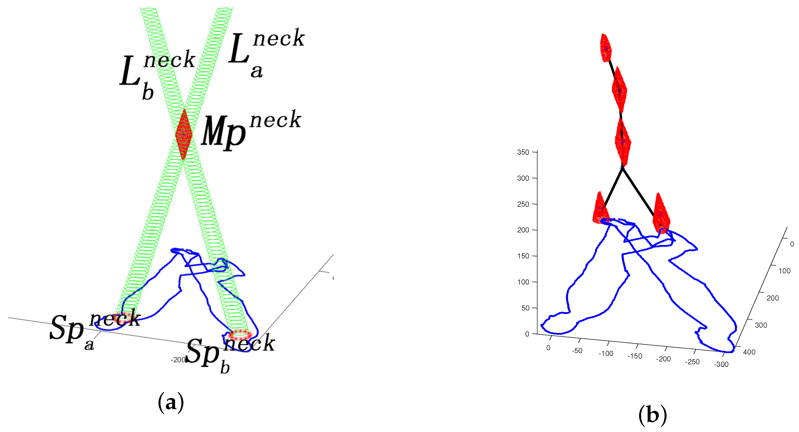
Figure 4.
Demo of SSSE procedure in a single light source scenario. (a) Pose classification based on major joint positions; (b) Spatial–temporal discrete human poses belonging to same class; (c) Temporal–spatial aggregation; (d) Three-dimensional (3D) human skeletonization.
Figure 4.
Demo of SSSE procedure in a single light source scenario. (a) Pose classification based on major joint positions; (b) Spatial–temporal discrete human poses belonging to same class; (c) Temporal–spatial aggregation; (d) Three-dimensional (3D) human skeletonization.
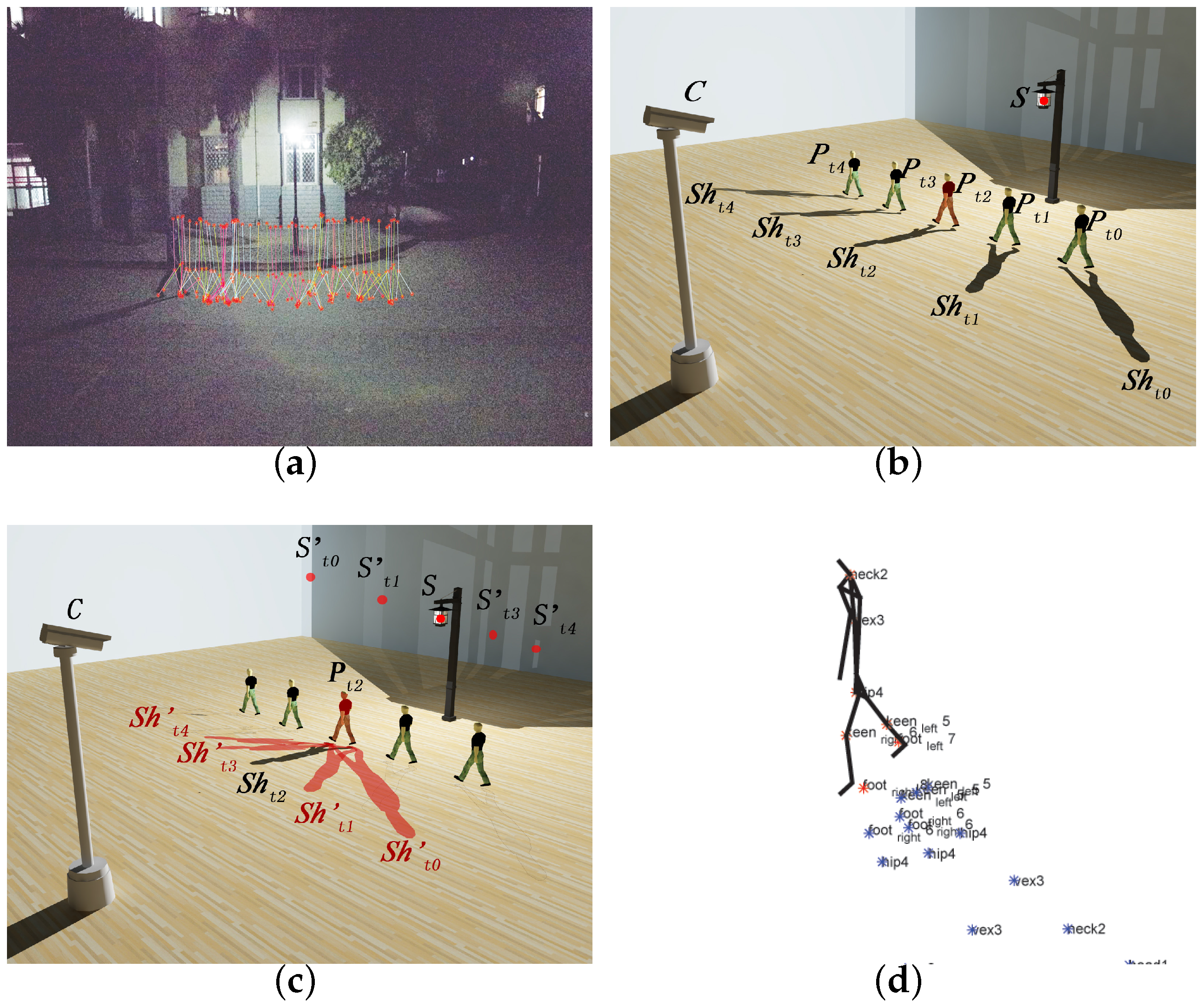
Figure 5.
The flow chart of skeleton synthesis procedure based on SSSE.

Figure 6.
Experimental results. (a) A comparison of tracking results; (b) Effective ranges of RGB-D-based results and SSSE-based results.
Figure 6.
Experimental results. (a) A comparison of tracking results; (b) Effective ranges of RGB-D-based results and SSSE-based results.
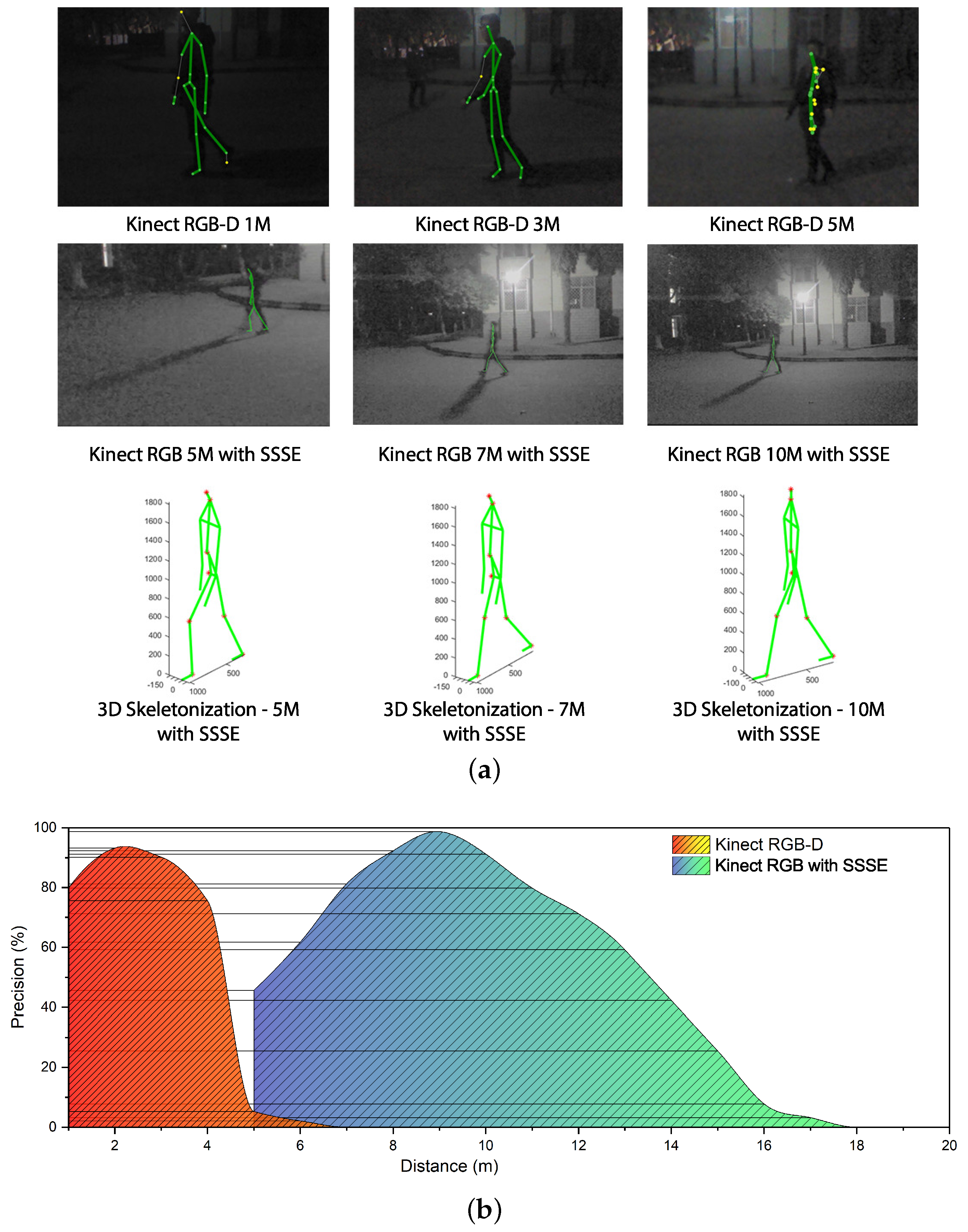
Figure 7.
Deviation between SSSE-extracted joints and ground truth.

Figure 8.
Maximum process capability test.

Table 1.
Result of unreliable joint position redress. is the precisely recovered joint rate. is the precisely recovered frame rate. is the number of unreliable joints. is the number of frames affected by unreliable joints. is the number of total recovered unreliable joint. is the number of inaccurately recovered joints. is the total number of recovered frames. is the number of frames containing inaccurately recovered joints.
| Test Set | Joints | Frames | ||||||
|---|---|---|---|---|---|---|---|---|
| Set No. | ||||||||
| 1 | 0.8644 | 1221 | 1111 | 56 | 0.7923 | 1385 | 1291 | 194 |
| 2 | 0.8554 | 1666 | 1516 | 91 | 0.7943 | 1218 | 1125 | 158 |
| 3 | 0.8357 | 1654 | 1519 | 137 | 0.8603 | 1293 | 1236 | 124 |
| 4 | 0.8636 | 1632 | 1532 | 123 | 0.8410 | 1377 | 1316 | 158 |
| 5 | 0.8391 | 1913 | 1764 | 159 | 0.7705 | 1176 | 1066 | 160 |
| 6 | 0.8929 | 1404 | 1348 | 94 | 0.7606 | 1198 | 1072 | 161 |
| 7 | 0.8816 | 1985 | 1842 | 92 | 0.8170 | 1048 | 973 | 117 |
| 8 | 0.8303 | 1254 | 1096 | 55 | 0.8189 | 1383 | 1287 | 154 |
| 9 | 0.8476 | 1907 | 1796 | 180 | 0.8264 | 1346 | 1236 | 124 |
| 10 | 0.8374 | 1516 | 1395 | 126 | 0.7877 | 1132 | 1049 | 157 |
| 11 | 0.7664 | 1944 | 1817 | 327 | 0.7190 | 1228 | 1132 | 249 |
| 12 | 0.7254 | 1135 | 992 | 169 | 0.7209 | 1063 | 970 | 204 |
| 13 | 0.7480 | 1446 | 1319 | 237 | 0.7092 | 1242 | 1159 | 278 |
| 14 | 0.7234 | 1129 | 996 | 179 | 0.6987 | 1037 | 941 | 216 |
| 15 | 0.7282 | 1076 | 944 | 160 | 0.7419 | 1247 | 1171 | 246 |
| 16 | 0.8029 | 1561 | 1492 | 239 | 0.7348 | 1269 | 1211 | 279 |
| 17 | 0.8113 | 1959 | 1892 | 303 | 0.7542 | 1414 | 1333 | 267 |
| 18 | 0.7999 | 1562 | 1470 | 221 | 0.6861 | 1138 | 1041 | 260 |
| 19 | 0.7806 | 1599 | 1486 | 238 | 0.6800 | 1039 | 942 | 236 |
| 20 | 0.7849 | 1589 | 1521 | 274 | 0.7445 | 1182 | 1100 | 220 |
| Total | 0.8149 | 31152 | 28848 | 3460 | 0.7655 | 24415 | 22651 | 3962 |
Table 2.
Comparison between external sensor information-based quadcopter monitoring methods.
| Methods | Device Requirement | Effective Range | Output Format | Joint Numbers |
|---|---|---|---|---|
| SSSE | Single RGB Camera | 7.0 m < < 10 m | Human Skeleton | 7 |
| Traditional RGB-D Method [20] | RGB-D Camera | 0.8 m < < 3.5 m | Human Skeleton | 20 |
| SSSE and RGB-D Fusion | RGB-D Camera | 0.8 m < < 10 m | Human Skeleton | 7 to 20 |
| Jafari’s RGB-D method [16] | RGB-D Camera | Not Available (N/A) | Human Voxel | 0 |
| Yang’s mono-RGB method [6] | Multiple RGB Cameras | N/A | Partial Voxels | 0 |
© 2017 by the authors. Licensee MDPI, Basel, Switzerland. This article is an open access article distributed under the terms and conditions of the Creative Commons Attribution (CC BY) license (http://creativecommons.org/licenses/by/4.0/).
Share and Cite
MDPI and ACS Style
Hou, J.; Guo, B.; He, W.; Wu, J. A 3D Human Skeletonization Algorithm for a Single Monocular Camera Based on Spatial–Temporal Discrete Shadow Integration. Appl. Sci. 2017, 7, 685. https://doi.org/10.3390/app7070685
AMA Style
Hou J, Guo B, He W, Wu J. A 3D Human Skeletonization Algorithm for a Single Monocular Camera Based on Spatial–Temporal Discrete Shadow Integration. Applied Sciences. 2017; 7(7):685. https://doi.org/10.3390/app7070685
Chicago/Turabian StyleHou, Jie, Baolong Guo, Wangpeng He, and Jinfu Wu. 2017. "A 3D Human Skeletonization Algorithm for a Single Monocular Camera Based on Spatial–Temporal Discrete Shadow Integration" Applied Sciences 7, no. 7: 685. https://doi.org/10.3390/app7070685
Note that from the first issue of 2016, this journal uses article numbers instead of page numbers. See further details here.