
Design of 4 × 1 Power Beam Combiner Based on MultiCore Photonic Crystal Fiber

1
Faculty of Engineering, Holon Institute of Technology (HIT), Holon 5810201, Israel
2
Faculty of Engineering, Bar Ilan University, Ramat-Gan 52900, Israel
*
Author to whom correspondence should be addressed.
Appl. Sci. 2017, 7(7), 695; https://doi.org/10.3390/app7070695
Submission received: 14 June 2017
/
Revised: 2 July 2017
/
Accepted: 3 July 2017
/
Published: 5 July 2017
(This article belongs to the Special Issue Solid State Lasers Materials, Technologies and Applications)
Abstract
:Featured Application
The proposed device can be very useful to high power and parametric applications.
Abstract
A novel concept of 4 × 1 power beam combiner based on multicore photonic crystal fiber is described. The light coupling obtained by integrating small air-holes in the multicore photonic crystal fiber (PCF) structure allows light coupling between coherent laser sources to the central core. The beam propagation method (BPM) and coupled mode theory were used for analyzing the proposed device. Simulation results show that four coherent fiber laser sources of 1 µm in a multicore PCF structure can be combined into one source after 2.6 mm light propagation, with a power efficiency of 99.6% and bandwidth of 220 nm. In addition, a higher 8 × 1 ratio combiner was demonstrated, based on the proposed device. Thus, the device can be very useful to combine beams.
1. Introduction
In 1961, the first laser based on neodymium (Nd3+) doped fiber was demonstrated [1,2]. Since then, fiber laser has been found as an efficient source for various applications, such as laser material processing [3], medical diagnostics [4], high power [5], metrology [6], imaging [7], etc. The most commonly used laser-active ion dopants in fibers are erbium (Er3+) and ytterbium (Yb3+) dopants, with their emission wavelengths around 1.5–1.6 µm and 1–1.1 µm, respectively [8,9].
The benefits of using a fiber laser as a light source: strong stability against thermo-optic effects, ease of use and higher gain, can be obtained by long fiber, while still keeping a compact cavity structure. Another advantage of fiber lasers is the capability to achieve output power values as high as 10 kW [10], using a single fiber laser. However, problems such as modal instabilities, thermal damage, and nonlinear effects, limit the power levels of a single fiber laser [11]. In order to overcome these problems, several beam combining methods were developed, such as the coherent beam combining [12], spectral beam combining [13], and incoherent beam combining [14].
Another solution is to use the combiner based on photonic crystal fiber (PCF). PCF is a versatile technology, based on a microstructured formation of low- and high-index materials [15]. Usually, the background material is pure silica (high-index), and the low-index areas are air holes along the fiber length.
PCF has unique characteristics [16,17] that do not exist in classical fibers such as high birefringence, larger single-mode areas, extremely low/high nonlinearity, and lower coupling length value between two closer cores. In recent years, research has demonstrated the potential of using PCF based coupler/splitter devices [17,18,19]. One of the recent improvements is the ability to obtain a smaller value of the coupling length compared to coupler/splitter based classical fibers.
Recently, the authors demonstrated a compact 4 × 1, 8 × 1 and 16 × 1 power combiner based on PCF [20]. The combining was achieved by replacing some air-holes areas with pure silica along the fiber length. However, this approach cannot be fabricated by fiber drawing methods [21,22,23]. In order to solve this problem, we propose a new approach that involves small air-holes in the PCF structure, which allows the control of light coupling between close cores without changing the refractive index structure. Thus, this technique can be used with the drawing and stack method for fabricating a combiner device based on multicore PCF. In this paper, we propose a new approach to obtain a multicore PCF that combined multiple laser sources to one source with high power level. The coupled mode theory and the beam propagation method [24,25] were used to investigate the performances of the 4 × 1 power combiner. In addition, a higher ratio of 8 × 1 combiner was designed using a cascade of two 4 × 1 power combiners and one 2 × 1 power combiner.
2. Principle of the Work
Figure 1 shows a schematic sketch of the multicore PCF 4 × 1 power combiner design based on the coupling between five cores (yellow color). The coefficients are the coupling coefficients between the cores: denotes the coupling between core 3 and core 1, or between core 2 and core 1. denotes the coupling between core 4 and core 1, or between core 5 and core 1. d is the diameter of the air-holes (white color), d is the diameter of the small air-holes (black color) and denotes the pitch—the distance between two air holes.
Classical coupled-mode equations can be used to analyze the light coupling between the five cores in the multicore PCF 4 × 1 power combiner. In our model, we integrated eight small air holes (black color), which leads to cancellation of other coupling that may occur between closer cores such as core 3–core 5, core 3–core 4, core 2–core 4, and core 2–core 5, and by assuming polarization independence, the solutions of the mode amplitudes can be given as
where Ar (r = 1,2,3,4,5) are the amplitudes of the fundamental mode in core r, is the propagation constant of the fundamental propagation mode, z is the propagation distance, is the amplitude constant, and is an eigenvalue. In our design, there are five cores, which mean that five coupled-mode equations can be used to describe our design. However, the combiner is based on multicore PCF with symmetrical hexagonal structure; in other words, the mode amplitude is equal in core 2–core 3 (A2 = A3) and core 4–core 5 (A4 = A5). Therefore, the five coupled-mode equations can be reduced to three equations which are given by
where the boundary conditions are given by
The three coupled-mode Equations (2)–(4) can be simplified to three linear equations, which are given by
The matrix system can be described as follows:
The eigenvalues and the eigenvectors can be found by solving the matrix system (Equation (9)). The field E(z) can be represented by a linear combination of the eigenvectors. In a particular solution, where = , a complete transfer of the energy from cores 2, 3, 4, and 5 to the central core 1, can be obtained. However, this condition depends on the geometrical parameter values of the multicore PCF structure (z, d, d′, and ). Therefore, optimization of the key parameters was done, in order to fulfill the necessary condition. In addition, this model can be duplicated, in order to design a higher ratio power such as 8 × 1 combiner.
3. Results: The Designs of 4 × 1 and 8 × 1 Power Combiners
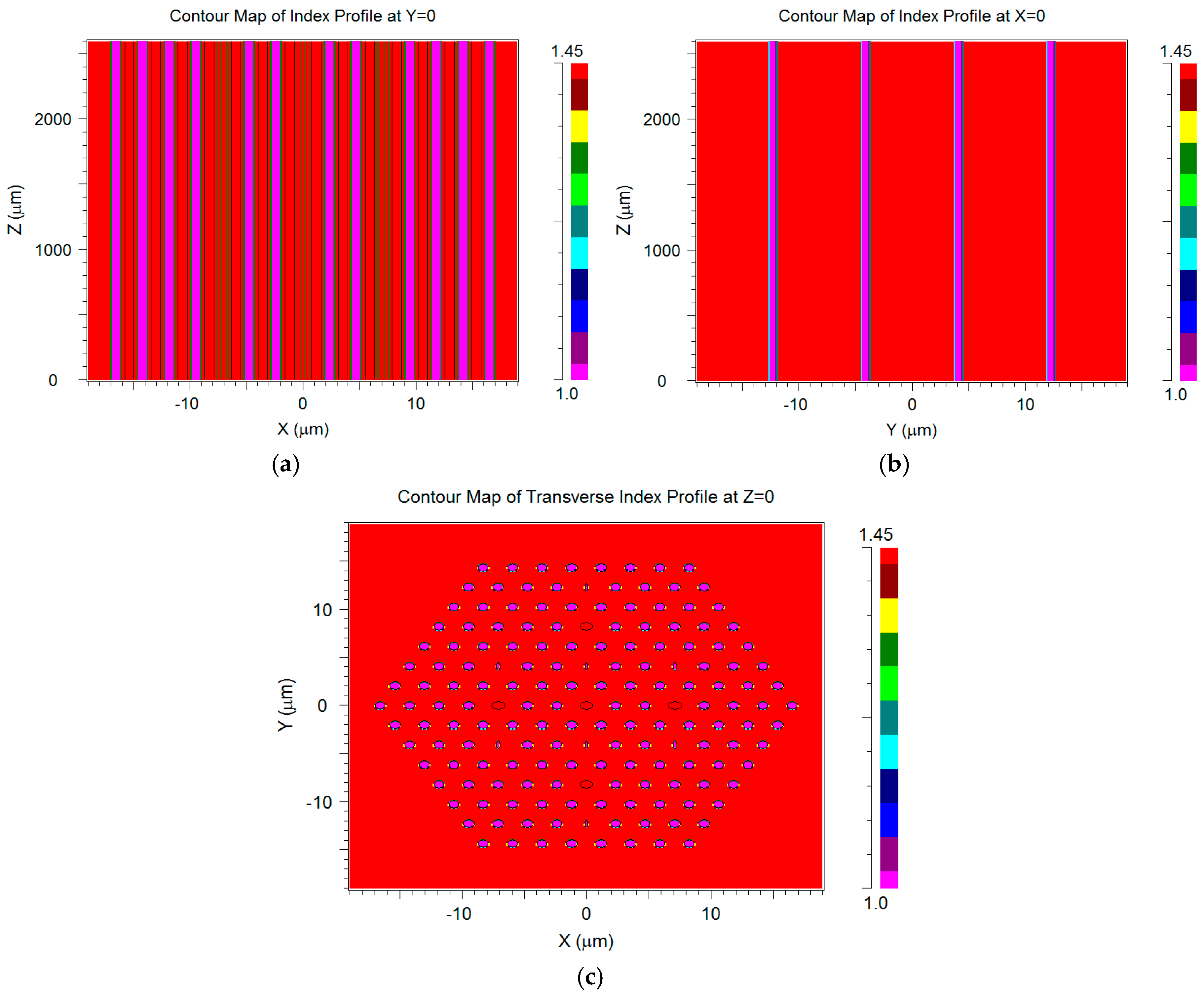
Figure 2a–c and Figure 3a–c shows the refractive index structure of the 4 × 1 power combiner and 8 × 1 power combiner, respectively. In these figures, the red color areas represent silica, and the purple color areas represent air.
The optimal values of the 4 × 1 power combiner multicore PCF structure are
The 8 × 1 power combiner is based on a cascade which includes two units of 4 × 1 power combiners and one unit of 2 × 1 power combiner, as shown in Figure 3a–c.
4. Simulation Results
The multicore PCF 4 × 1 power combiner structure was simulated using RSoft Photonics CAD software (5.1.5, RSoft, Ossining, NY, USA), based on BPM.
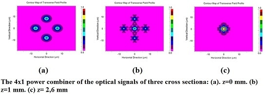
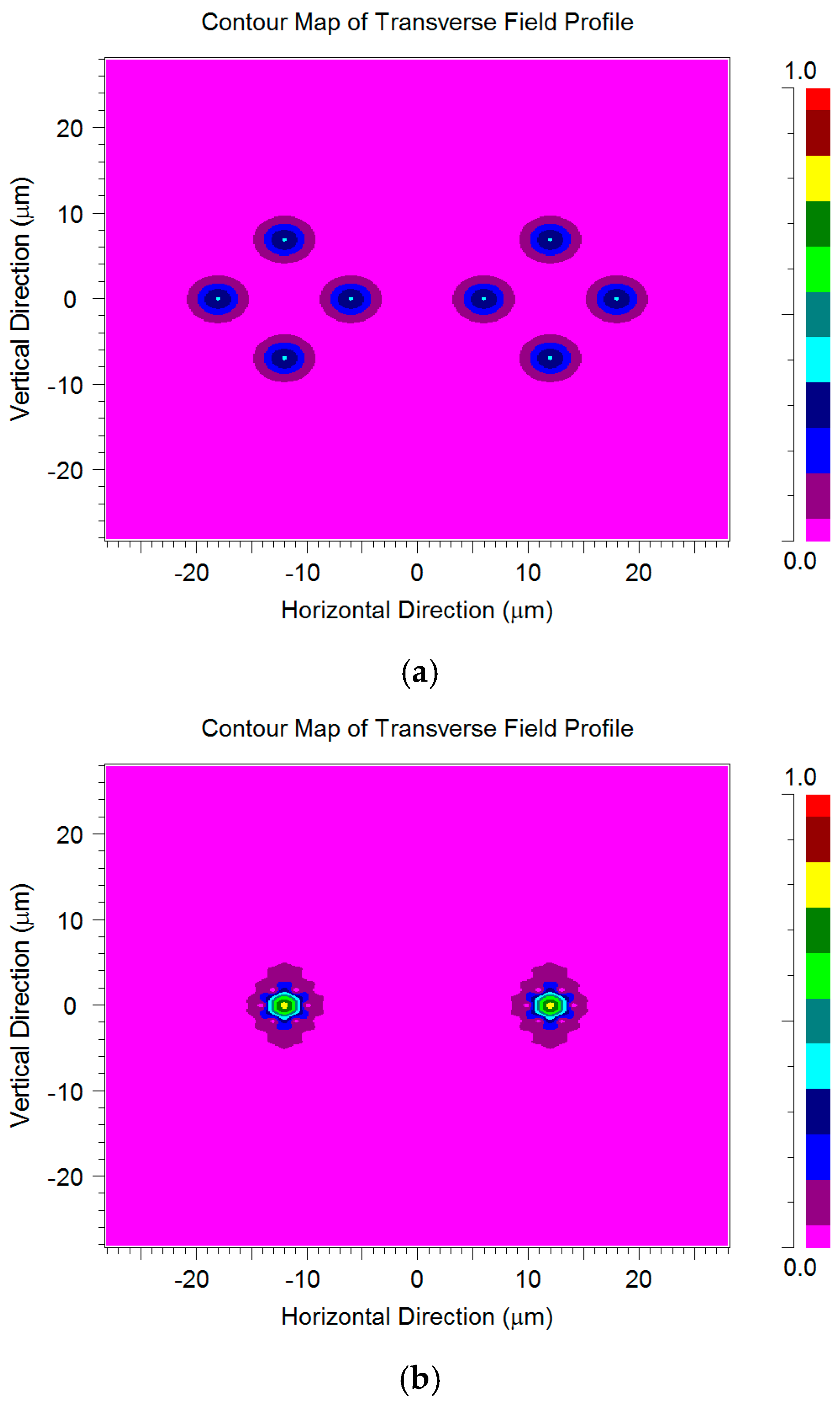
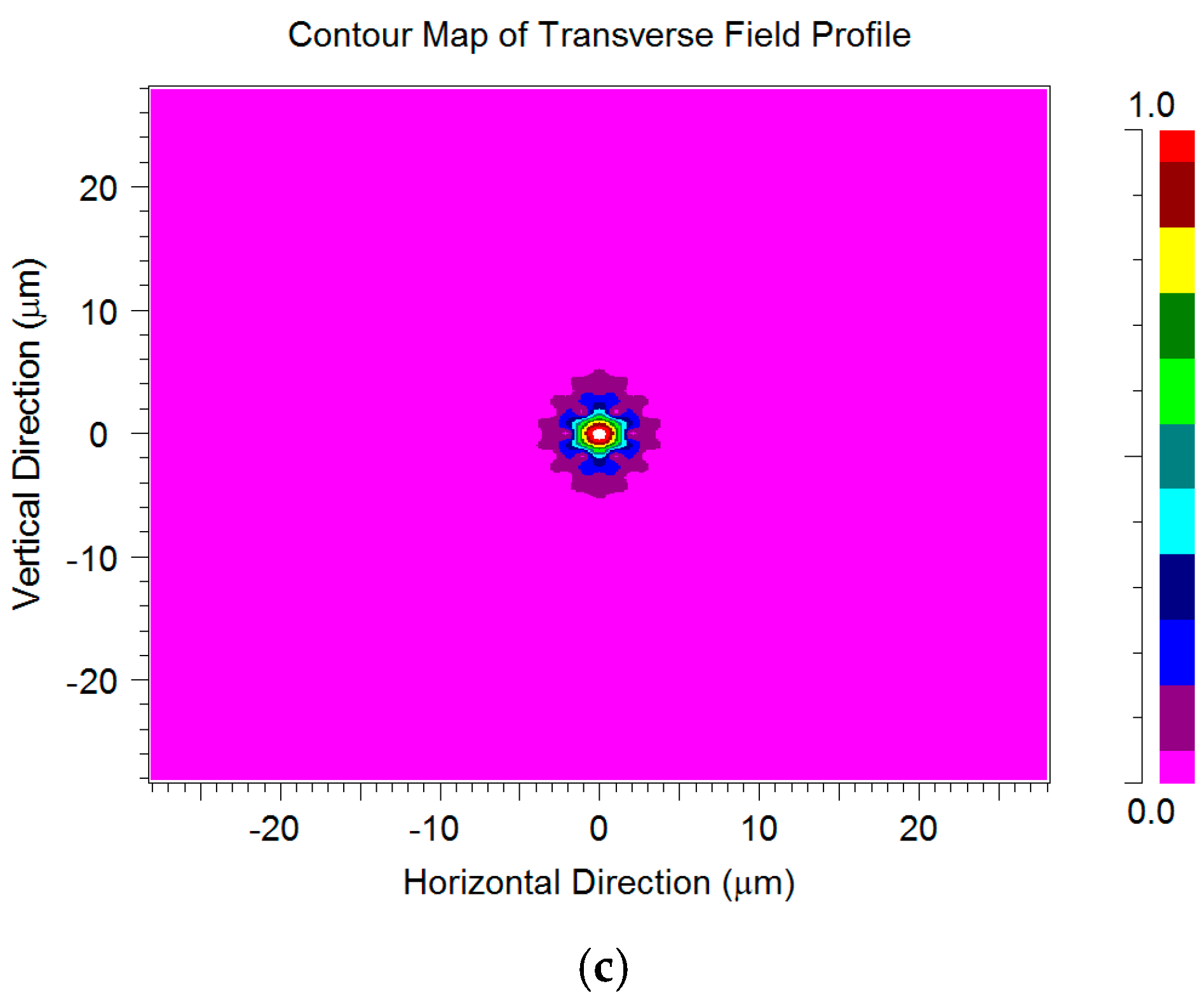
Figure 4a shows the transmission of four Gaussian sources at a 1 µm wavelength at z = 0, with a normalized power value of 0.25. Figure 4b shows the light coupling between the central core to the other four cores at z = 1 mm. Figure 4c shows that four Gaussian sources are combined to one source at z = 2.6 mm, with 99.6% of the total power.
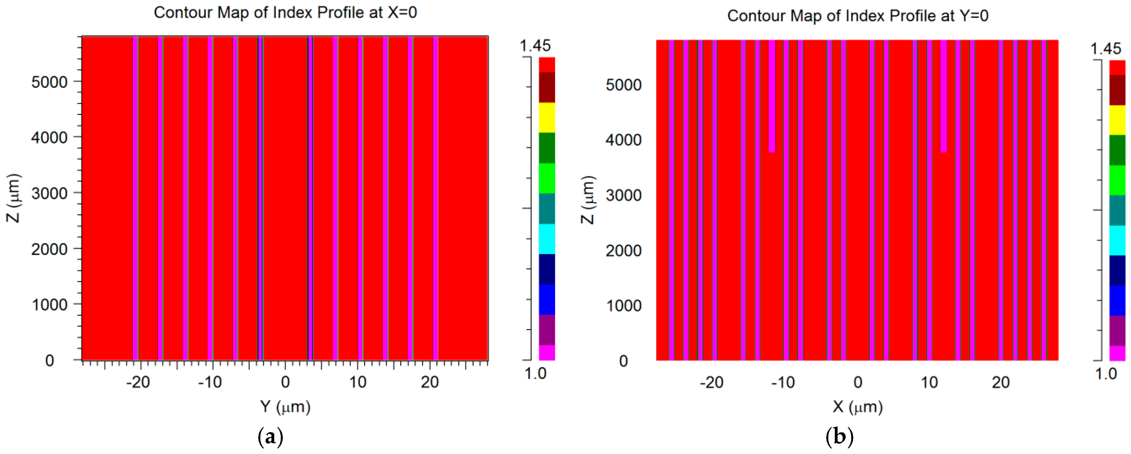
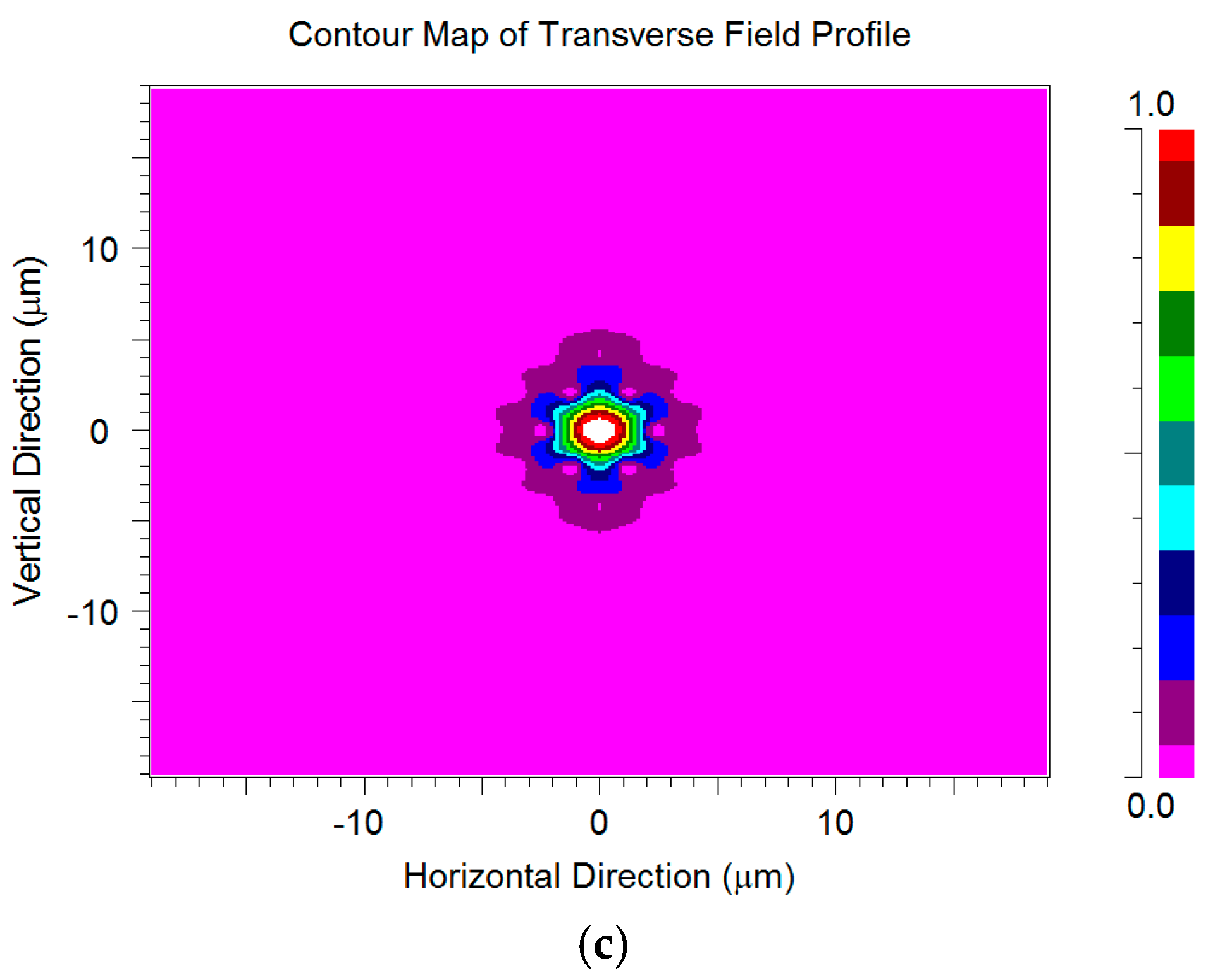
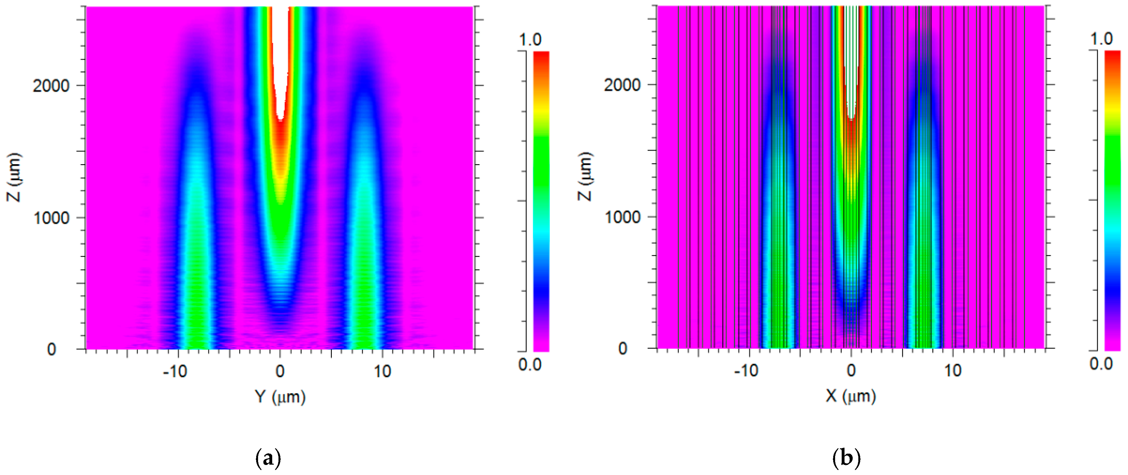
The proposed device can also act as a two dimensional (2D) 2 × 1 power combiner, as shown in Figure 5a,b.
In addition, a MATLAB script code, combined with BPM simulations, was developed to examine the sensitivity of the proposed device to the wavelength variation of the laser sources around 1 µm. Figure 6 shows power attenuation around the central wavelength (1 µm).
It can be noticed from Figure 6 that the bandwidth (FWHM) of the 4 × 1 power combiner is about 220 nm in the 900–1120 nm range. Such a bandwidth implies that this combiner may be suitable for tunable lasers around a wavelength of 1000 nm, and can support broadband sources. This provides many benefits, due to the fact that within this range, one can use optical lasers such as ytterbium doped fiber laser, which is highly useful for high power and parametric applications.
This device can be also used in cascade configuration for obtaining a higher ratio of combining. For example, we used two units of the 4 × 1 power combiner and connected them to a 2 × 1 combiner, in order to obtain an 8 × 1 power combiner. Figure 7a shows the transmission of eight Gaussian sources at a 1 µm wavelength at z = 0, with a normalized power value of 0.125. Figure 7b shows the combining of eight sources to two at z = 2.6 mm. Figure 7c shows that eight Gaussian sources are combined to one single mode at z = 5.8 mm.
5. Conclusions
In this article, we have shown a new approach of designing specific air holes in a multicore PCF structure that are utilized to obtain an optical 4 × 1 power combiner.
Through BPM simulation results, we showed that the energies of four optical signals at 1 µm wavelength can be combined into one source output in a PCF structure with dimensions of 38 μm × 38 μm × 2.6 mm. The amount of total power at the output is about 99.6% of the input power, the coupling losses between core 1–core 2/3/4/5 is about 0.01% of the input power, and the optical bandwidth value is 220 nm for the output port. Thus, this combiner device can be used in high power and parametric applications.
This combiner can be fabricated by stacking and drawing techniques which are simpler than other known fabrication techniques [20]. It is important to emphasize that all of these combiners were demonstrated using simulation.
In addition, a higher level 8 × 1 combiner was demonstrated using two units of 4 × 1 connected to a 2 × 1 combiner in a cascade configuration.
This research could be expanded to optical combiners with larger numbers of input fiber laser sources, such as 16 × 1 and 32 × 1.
Author Contributions
Dror Malka envisioned the project. Zeev Zalevsky provided guidance and funding. Dror Malka designed the device and performed simulations with support of Eyal Cohen, Dror Malka, Eyal Cohen, and Zeev Zalevsky wrote the manuscript text. Dror Malka made the figures and all authors reviewed the manuscripts.
Conflicts of Interest
The authors declare no conflict of interest.
References
- Snitzer, E. Optical maser action of Nd+3 in a barium crown glass. Phys. Rev. Lett. 1961, 7, 444–446. [Google Scholar] [CrossRef]
- Snitzer, E.; Hoffman, F.; Crevier, R. Neodymium-glass-fiber laser. J. Opt. Soc. Am. 1963, 53, 515–517. [Google Scholar]
- Je, G.; Malka, D.; Kim, H.; Hong, S.; Shin, B. A study on micro hydroforming using shock wave of 355 nm UV-pulsed laser. Appl. Surf. Sci. 2017, 417, 244–249. [Google Scholar] [CrossRef]
- Ushenko, Y.A.; Arkhelyuk, A.D.; Sidor, M.I.; Bachynskyi, V.T.; Wanchuliak, O.Y. Laser polarization autofluorescence of endogenous porphyrins of optically anisotropic biological tissues and fluids in diagnostics of necrotic and pathological changes of human organs. Appl. Opt. 2014, 53, B181–B191. [Google Scholar] [CrossRef] [PubMed]
- Ding, D.; Lv, X.; Chen, X.; Wang, F.; Zhang, J.; Che, K. Tunable high-power blue external cavity semiconductor laser. Opt. Laser Technol. 2017, 94, 1–5. [Google Scholar] [CrossRef]
- Jones, T.B.; Otterstrom, N.; Jackson, J.; Archibald, J.; Durfee, D.S. Laser wavelength metrology with color sensor chips. Opt. Express 2015, 23, 32471–32480. [Google Scholar] [CrossRef] [PubMed]
- Wang, Y.; Wang, Y.; Le, H.Q. Multi-spectral mid-infrared laser stand-off imaging. Opt. Express 2005, 13, 6572–6586. [Google Scholar] [CrossRef] [PubMed]
- Yahel, E.; Hardy, A. Modeling High-Power Er3+-Yb3+ Codoped Fiber Lasers. J. Lightwave Technol. 2003, 21, 2044. [Google Scholar] [CrossRef]
- Vienne, G.G.; Caplen, J.E.; Dong, L.; Minelly, J.D.; Nilsson, J.; Payne, D.N. Fabrication and Characterization of Yb3+: Er3+ Phosphosilicate Fibers for Lasers. J. Lightwave Technol. 1998, 16, 1990. [Google Scholar] [CrossRef]
- Stiles, E. New developments in IPG fiber laser technology. In Proceedings of the 5th International Workshop on Fiber Lasers, Dresden, Germany, 30 September–1 October 2009. [Google Scholar]
- Dawson, J.W.; Messerly, J.M.; Beach, R.J.; Shverdin, M.Y.; Stappaerts, E.A.; Sridharan, A.K.; Pax, P.H.; Heebner, J.E.; Siders, C.W.; Barty, C.P.J. Analysis of the scalability of diffraction-limited fiber lasers and amplifiers. Opt. Express 2008, 16, 13240–13266. [Google Scholar] [CrossRef]
- Liu, Z.; Zhou, P.; Xu, X.; Wang, X.; Ma, Y. Coherent beam combining of high power fiber lasers: Progress and prospect. Sci. China Technol. Sci. 2013, 56. [Google Scholar] [CrossRef]
- Drachenberg, D.; Divliansky, I.; Smirnov, V.; Venus, G.; Glebov, L. High Power Spectral Beam Combining of Fiber Lasers with Ultra High Spectral Density by Thermal Tuning of Volume Bragg Gratings. In SPIE: Fiber Lasers VIII: Technology, Systems, and Applications, San Francisco, CA, USA, 22 January 2011; SPIE: Bellingham, WA, USA, 2011; Volume 7914, p. 79141F. [Google Scholar]
- Shamir, Y.; Zuitlin, R.; Sintov, Y.; Shtaif, M. High brightness efficient beam combining of 3 kW 1.07 μm fiber lasers with very low thermal dissipation. In Proceedings of the OASIS, Meeting on Optical Engineering and Science, Tel Aviv, Israel, 19–20 February 2013. [Google Scholar]
- Russell, P.S.J. Photonic-crystal fibers. J. Lightwave Technol. 2006, 24, 4729–4749. [Google Scholar] [CrossRef]
- Broeng, J.; Mogilevstev, D.; Barkou, S.E.; Bjarklev, A. Photonic crystal fibers: A new class of optical waveguides. Opt. Fiber Technol. 1999, 5, 305–330. [Google Scholar] [CrossRef]
- Elbaz, D.; Malka, D.; Zalevsky, Z. Photonic crystal fiber based 1 × N intensity and wavelength splitters/couplers. Electromagnetics 2013, 32, 209–220. [Google Scholar] [CrossRef]
- Malka, D.; Zalevsky, Z. Multicore Photonic Crystal Fiber Based 1 × 8 Two-Dimensional Intensity Splitters/Couplers. Electromagnetics 2013, 33, 413–420. [Google Scholar] [CrossRef]
- Malka, D.; Peled, A. Power Splitting of 1 × 16 in Multicore Photonic Crystal Fibers. Appl. Surf. Sci. 2017, 417, 34–39. [Google Scholar] [CrossRef]
- Malka, D.; Sintov, Y.; Zalevsky, Z. Fiber-laser monolithic coherent beam combiner based on multicore photonic crystal fiber. Opt. Eng. 2014, 54, 011007. [Google Scholar] [CrossRef]
- Mortimore, D.B. Theory and fabrication of 4 × 4 single-mode fused optical fiber couplers. Appl. Opt. 1990, 29, 371–374. [Google Scholar] [CrossRef] [PubMed]
- Kumar, A.; Varshney, R.K.; Sinha, R.K. Scalar modes and coupling characteristics of eight-port waveguide couplers. J. Lightwave Technol. 1989, 7, 293–296. [Google Scholar] [CrossRef]
- Mortimore, D.B.; Arkwright, J.W. Monolithic wavelength-falt-tened 1 × 7 single-mode fused fiber couplers: Theory, fabrication and analysis. Appl. Opt. 1991, 30, 650–659. [Google Scholar] [CrossRef] [PubMed]
- Haus, H.A.; Huang, W. Coupled-Mode Theory. Proc. IEEE 1991, 79, 1505–1517. [Google Scholar] [CrossRef]
- Katz, O.; Malka, D. Design of novel SOI 1 × 4 optical power splitter using seven horizontally slotted waveguides. Photonics Nanostruct. Fundam. Appl. 2017, 25, 9–13. [Google Scholar] [CrossRef]
Figure 1.
Schematic sketch of the 4 × 1 power combiner design at the x–y plane.
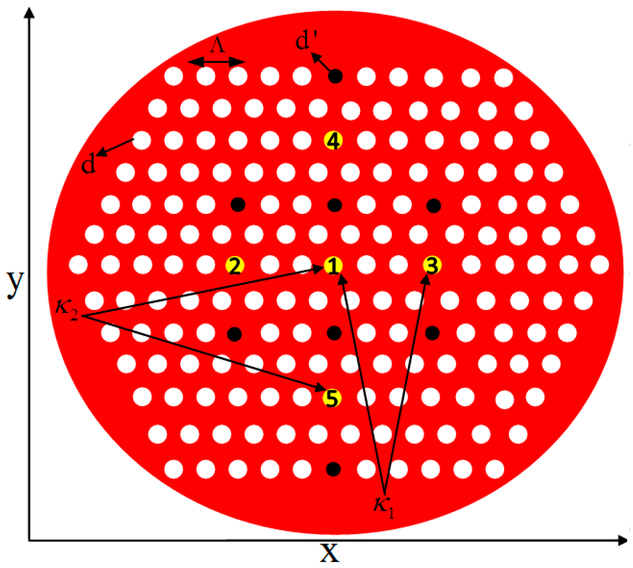
Figure 2.
Refractive index profiles of the 4 × 1 power combiner: (a) xz plane at y = 0; (b) yz plane at x = 0; (c) xy plane at z = 0.
Figure 2.
Refractive index profiles of the 4 × 1 power combiner: (a) xz plane at y = 0; (b) yz plane at x = 0; (c) xy plane at z = 0.

Figure 3.
Refractive index profiles of the 8 × 1 power combiner: (a) xz plane at y = 0; (b) yz plane at x = 0; (c) xy plane at z = 0.
Figure 3.
Refractive index profiles of the 8 × 1 power combiner: (a) xz plane at y = 0; (b) yz plane at x = 0; (c) xy plane at z = 0.

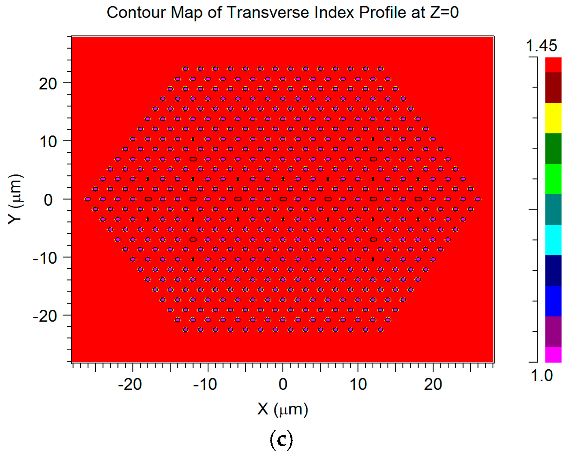
Figure 4.
The 4 × 1 power combiner of the optical signals (λ = 1 µm) of three xy cross sections: (a) z = 0 mm, (b) z = 1 mm; (c) z = 2.6 mm.
Figure 4.
The 4 × 1 power combiner of the optical signals (λ = 1 µm) of three xy cross sections: (a) z = 0 mm, (b) z = 1 mm; (c) z = 2.6 mm.
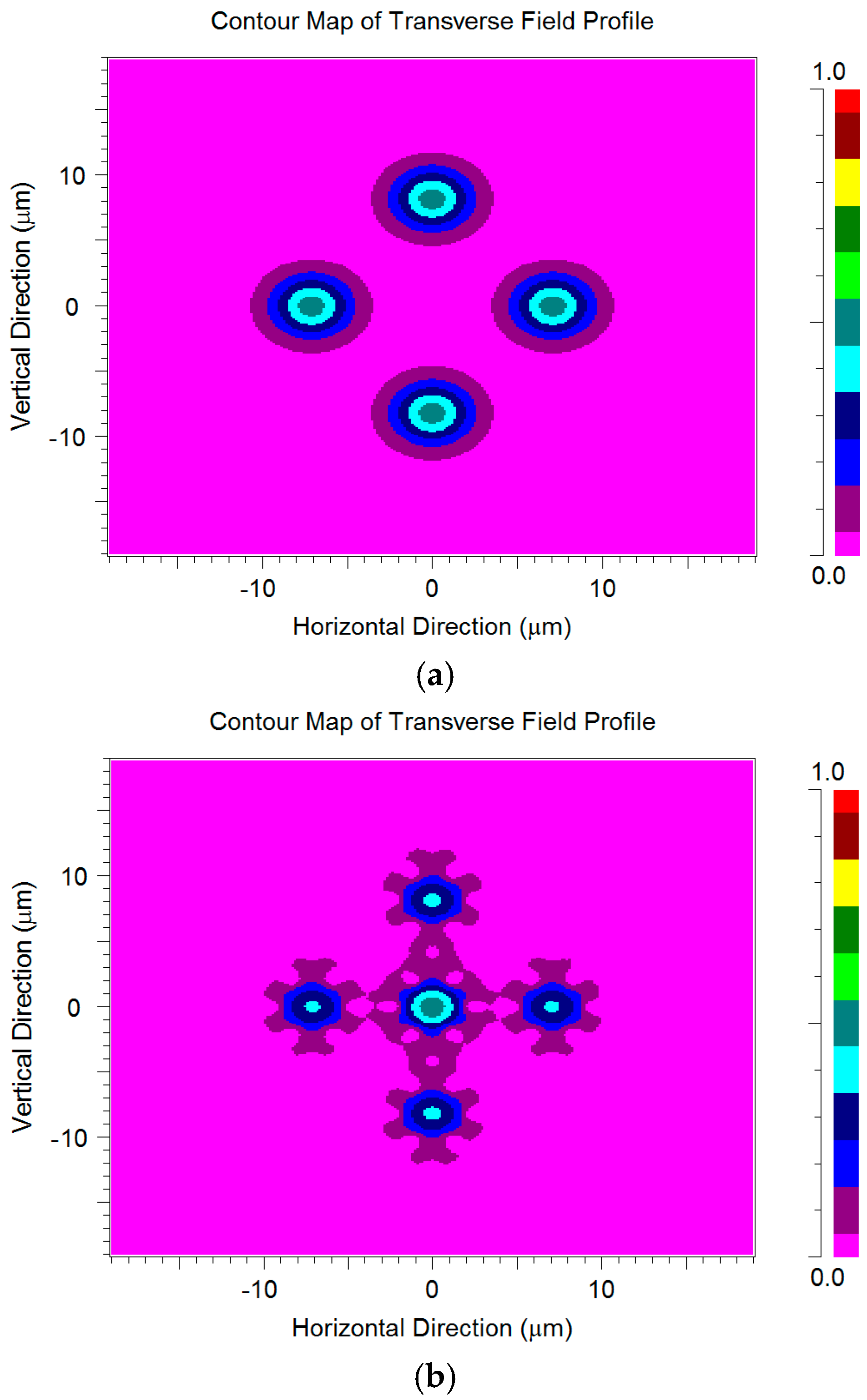

Figure 5.
Two dimensional (2D) 2 × 1 power combiner of the optical signals (λ= 1 µm): (a) yz plane; (b) xz plane.
Figure 5.
Two dimensional (2D) 2 × 1 power combiner of the optical signals (λ= 1 µm): (a) yz plane; (b) xz plane.

Figure 6.
Normalized power in the central core at z = 2.6 mm as a function of wavelength.
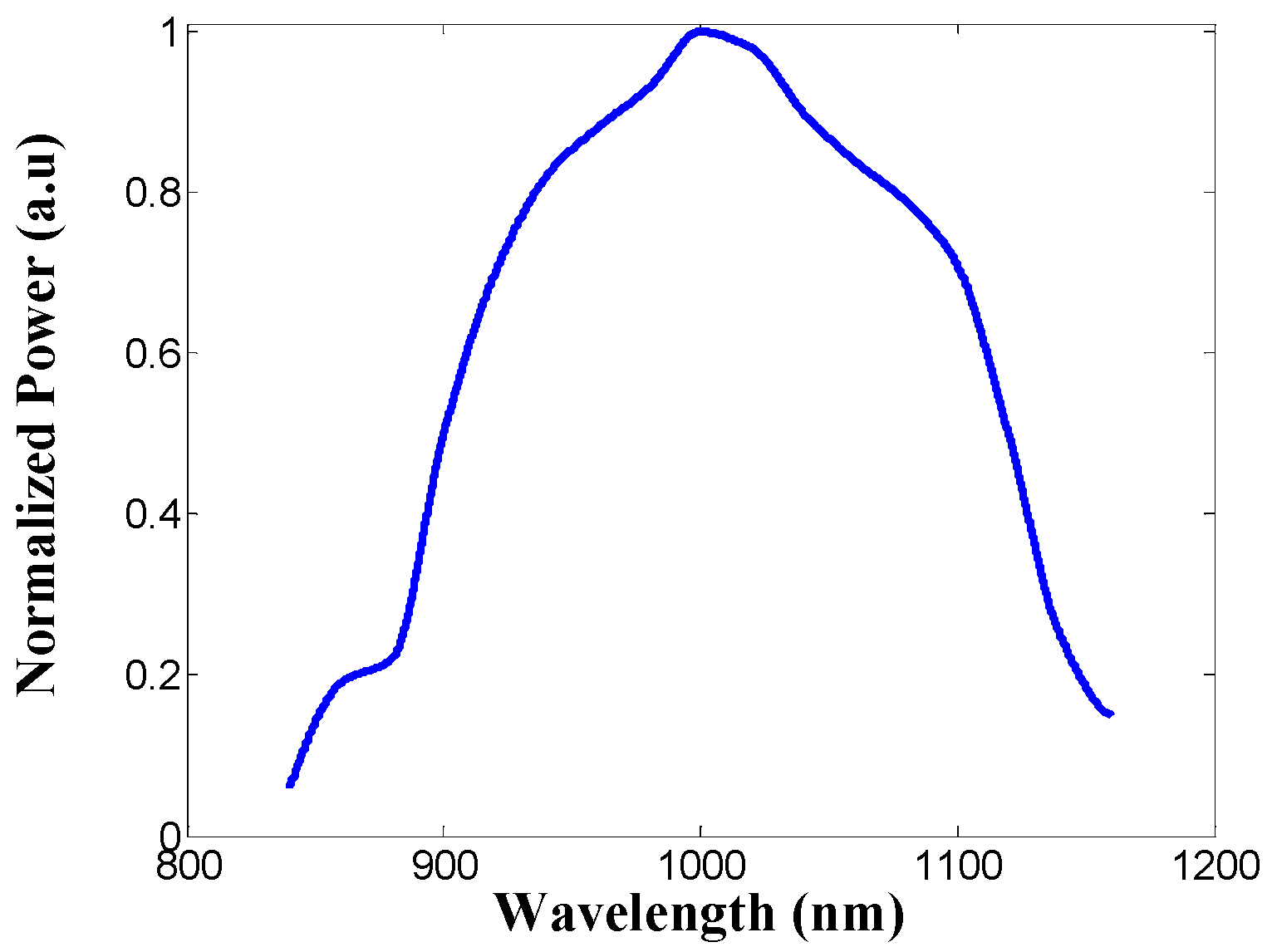
Figure 7.
The 8 × 1 power combiner of the optical signals (λ = 1 µm) of three xy cross sections: (a) z = 0 mm; (b) z = 2.6 mm; (c) z = 5.8 mm.
Figure 7.
The 8 × 1 power combiner of the optical signals (λ = 1 µm) of three xy cross sections: (a) z = 0 mm; (b) z = 2.6 mm; (c) z = 5.8 mm.

© 2017 by the authors. Licensee MDPI, Basel, Switzerland. This article is an open access article distributed under the terms and conditions of the Creative Commons Attribution (CC BY) license (http://creativecommons.org/licenses/by/4.0/).
Share and Cite
MDPI and ACS Style
Malka, D.; Cohen, E.; Zalevsky, Z. Design of 4 × 1 Power Beam Combiner Based on MultiCore Photonic Crystal Fiber. Appl. Sci. 2017, 7, 695. https://doi.org/10.3390/app7070695
AMA Style
Malka D, Cohen E, Zalevsky Z. Design of 4 × 1 Power Beam Combiner Based on MultiCore Photonic Crystal Fiber. Applied Sciences. 2017; 7(7):695. https://doi.org/10.3390/app7070695
Chicago/Turabian StyleMalka, Dror, Eyal Cohen, and Zeev Zalevsky. 2017. "Design of 4 × 1 Power Beam Combiner Based on MultiCore Photonic Crystal Fiber" Applied Sciences 7, no. 7: 695. https://doi.org/10.3390/app7070695
Note that from the first issue of 2016, this journal uses article numbers instead of page numbers. See further details here.