
Vibration Control Design for a Plate Structure with Electrorheological ATVA Using Interval Type-2 Fuzzy System


1
Graduate Institute of Automation Technology, National Taipei University of Technology, Taipei 10608, Taiwan
2
Department of Mechanical Engineering, National Taipei University of Technology, Taipei 10608, Taiwan
*
Author to whom correspondence should be addressed.
Appl. Sci. 2017, 7(7), 707; https://doi.org/10.3390/app7070707
Submission received: 16 May 2017
/
Revised: 30 June 2017
/
Accepted: 3 July 2017
/
Published: 8 July 2017
(This article belongs to the Special Issue Selected Papers from the 2016 International Conference on Inventions)
Abstract
:This study presents vibration control using actively tunable vibration absorbers (ATVA) to suppress vibration of a thin plate. The ATVA is made of a sandwich hollow structure embedded with electrorheological fluid (ERF). ERF is considered to be one of the most important smart fluids and it is suitable to be embedded in a smart structure due to its controllable rheological property. ERF’s apparent viscosity can be controlled in response to the electric field and the change is reversible in 10 microseconds. Therefore, the physical properties of the ERF-embedded smart structure, such as the stiffness and damping coefficient, can be changed in response to the applied electric field. A mathematical model is difficult to be obtained to describe the exact characteristics of the ERF embedded ATVA because of the nonlinearity of ERF’s viscosity. Therefore, a fuzzy modeling and experimental validations of ERF-based ATVA from stationary random vibrations of thin plates are presented in this study. Because Type-2 fuzzy sets generalize Type-1 fuzzy sets so that more modeling uncertainties can be handled, a semi-active vibration controller is proposed based on Type-2 fuzzy sets. To investigate the different performances by using different types of fuzzy controllers, the experimental measurements employing both type-1 fuzzy and interval type-2 fuzzy controllers are implemented by the Compact RIO embedded system. The fuzzy modeling framework and solution methods presented in this work can be used for design, performance analysis, and optimization of ATVA from varying harmonic vibration of thin plates.
1. Introduction
Smart materials and vibration control technology can suppress vibration of flight vehicles and allow them to operate beyond the traditional flutter boundary, improve ride comfort, and minimize vibration fatigue damage [1]. Due to the controllable and varied physical properties of smart materials, they are also used for living infrastructures, mechanical structures, and seismic vibration controls for decades [2,3,4,5,6,7,8,9,10,11,12,13,14,15,16,17,18,19,20,21,22,23,24,25,26,27,28,29,30,31,32,33,34,35]. Smart materials and structures that possess electromechanical characteristics have been widely used for active vibration control or semi-active vibration control, such as piezoelectric damper [4,5,6,7,8], eddy current damper [9], magnetostrictive spring [10], magneto-rheological fluid (MRF) damper [11,12,13], electro-rheological fluid (ERF) damper [14,15,16,17], shape memory alloy (SMA) [18,19,20,21], and electromagnetic and piezoelectric shunt damper [22,23,24,25,26,27,28,29,30,31,32,33,34,35]. Smart materials have one or more properties changed by the external stimuli, such as temperature, stress, electric field or magnetic field. Active vibration control uses piezoelectric ceramics to generate the force or displacement based on the external applied voltage [4,5,6,7,8,9]. To suppress the structure’s vibration, ERF and MRF dampers are widely used as semi-active element in suspension systems [11,12,13,14,15,16,17]. ER and MR fluids are transformed from the liquid state into the solid state in milliseconds by applying an electric or a magnetic field. Shape memory alloys can change its material properties based on temperature [18,19,20,21].
Since Frahm proposed the original dynamic vibration absorber (DVA) in a decade, DVAs are successfully applied in the vibration control of civil structures, naval architectures, and aerospace [36,37]. The DVA consist of a stiffness element, a damping component, and an oscillator. The working principle of the DVA is to transfer the vibration energy to the oscillators by a specified design for a certain frequency range. Because the effective working frequency span of DVAs is narrow only for a certain designed frequency range, Den Hartog et al. considered the optimal tuning of the absorber parameters including damping to improve the DVA’s design [38]. Furthermore, the optimal determinations of parameters were investigated for the absorber with nonlinear damping and different loading characteristics in the following studies [39]. Among the above studies, the absorbers’ parameters are constant and time invariant; therefore, the vibration absorber is passive. To improve the performance of the passive vibration absorbers, many researchers investigated semi-active and active designs [40,41]. The semi-active absorbers have the capability of tuning their working resonant frequencies by adjusting the stiffness and/or damping of the absorbers. One of the adjustments can be realized either through the active change of geometry or through the material properties of the constituents. Thus, they are called actively tuned vibration absorbers (ATVAs) [42]. The other types of ATVA are made of the smart materials whose physical properties can be controlled by the external input. Among all ATVA designs, the ones involved with the use of smart materials, such as piezoelectric materials [4,5,6,7,8,9], magnetorheological elastomer (MRE) [12], electrorheological fluid (ERF) [16,17], and shape memory alloy and shape memory polymer [19], are frequently seen. ATVAs have advantages of being more stable in system performance and simpler in controller design.
Since Winslow discovered the electrorheological effect [43], the reversible and controllable material properties make ERF attractive for many applications, such as vibration dampers, shock absorbers, clutches, and valves [44,45,46,47,48,49]. ERFs comprise micrometer-size dielectric particles in insulating liquid, so that their apparent viscosity is varying in response to the applied electric field. Based on electrorheological properties of ERFs, many researchers developed different applications and systems using ERF. For a hollow cantilevered beam filled with ER fluid, in the absence of the electric field, the ERF produces the shear force only caused by the fluid resistance. However, if a certain level of electric field is supplied to the ERF, a shear stiffness arises owing to the pre-yielding behavior of the ERF. Therefore, the stiffness of the beam can be tuned by controlling the intensity of the electric field applied to the ERF. Choi et al. investigated the vibration properties for hollow cantilevered beams filled with ER fluid and derived an empirical model for predicting the vibration characteristics in responding to electric field [48]. Many studies focus on the progress of ER materials in modeling the mechanisms and rheology of electrorheological fluids. There are several literature reviews about material properties including water-containing system such as silica gel, polymer, cellulose, and water-free system such as aluminosilicate, carbonaceous, semiconducting polymers [50,51,52,53,54,55,56,57]. During the past decades, effective semi-active suspension and absorber systems featuring ERF has been proposed by many investigators. Yalcintas et al. proposed a semi-active vibration control for ER adaptive beams and illustrated their capabilities by experiments [58]. Rahn et al. designed a feedback vibration controller for the cantilevered ER beam [59]. Wei et al. studied the vibration control of rotating flexible beams and investigated the feasibility of ER fluids by experiments [60]. Choi et al. proposed an ER damper for cylindrical suspension system of small-sized vehicles [61]. However, because ER fluids change from Newtonian flow to Bingham plastic with response to the applied electric field, the damping and stiffness of the ATVA is very nonlinear. Therefore, accurate parameters of ERF models are generally difficult to obtain so that there are modeling uncertainties for the ATVA systems. The vibration controller must have the adaptive capability and the robustness to the modeling uncertainties and the external disturbance.
The damping force of ERF consists a viscous damping without an electric field. With an electric field, The ERF can provide a Coulomb friction damping force for vibration control. Generally, the Coulomb friction damping force is in proportion to the square of voltage applied to the ERF [62]. The relation between the applied voltage and the Coulomb friction is intensively nonlinear. The controller based on the linear control theory is difficult to design to achieve the required performance. Therefore, these systems were mostly modeled by highly nonlinear differential equations, thus making it difficult when considering controller design. Various controller design schemes were proposed to manipulate ERF absorber systems, such as the intelligent control, adaptive control, and robust control. Takawa et al. designed a fuzzy controller to deal with the nonlinearity for a hybrid smart composite beam actuated by piezoceramics and ERF [62]. Choi et al. proposed a robust control of electrorheological suspension system subjected to parameter uncertainties associated with sprung mass of the vehicle and the ER damper [63].
Because the membership functions of type-1 fuzzy sets do not have uncertainties associated with them, the modeling uncertainties of ERF cannot be described in the membership function of the type-1 fuzzy set. Recently, more and more researchers around the world are studying about type-2 fuzzy sets and systems for various applications [64,65,66,67,68,69,70,71,72,73,74,75,76]. Membership functions of type-2 fuzzy set are different from the one of type-1 fuzzy set. For type-2 fuzzy sets, the membership functions are three-dimensional. The first two dimensions are the same as the type-1 fuzzy set, but the third dimension is called its footprint of uncertainty (FOU). An interval type-2 fuzzy set was proposed to reduce the complicated computation of type-2 fuzzy set [73]. Because the third-dimension value of the interval type-2 fuzzy sets is the same everywhere, the FOU can be used to describe the third dimension value. To improve the performance of the ATVA, we proposed an interval type-2 semi-active controller to deal with the modeling uncertainties and the nonlinearity of ERF.
This paper is organized as follows. Section 2 describes the fabrication of the ERF sandwich beam and the characteristic measurement of the ERF embedded ATVA in the frequency domain. It also describes the experimental setup to measure the dynamic response of the ERF embedded sandwich beam. Section 3 describes the design and analysis of a thin plate with the ERF embedded ATVA to suppress its varying harmonic vibration. The governing equations for this structure were derived by using principle of minimum total potential energy. The ANSYS software is used to simulate the vibration’s frequency response for the different applied electric fields to the ERF. In Section 4, the frequency response of the smart structure is measured to establish the fuzzy expert database for the vibration controller. Based on the experimental results, a type-2 fuzzy controller is proposed to accomplish the semi-active vibration control. In Section 5, the real-time vibration control is performed to validate the proposed controller using NI compact RIO. Finally, Section 6 draws conclusions.
2. Sandwich-Type ATVA with ER Materials Embedded
2.1. Design of the Sandwich ATVA with ER Materials Embedded
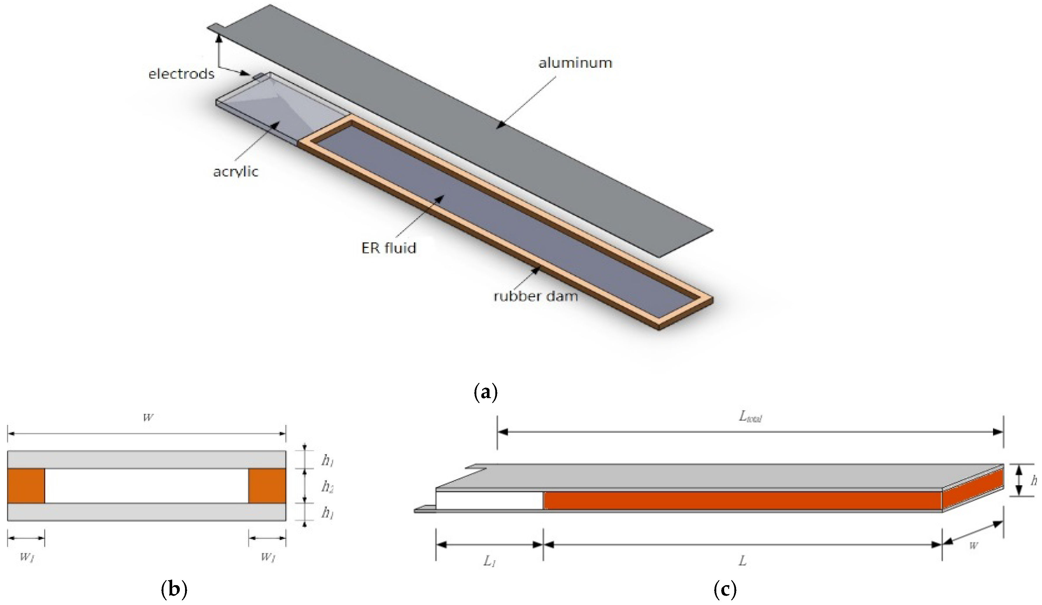
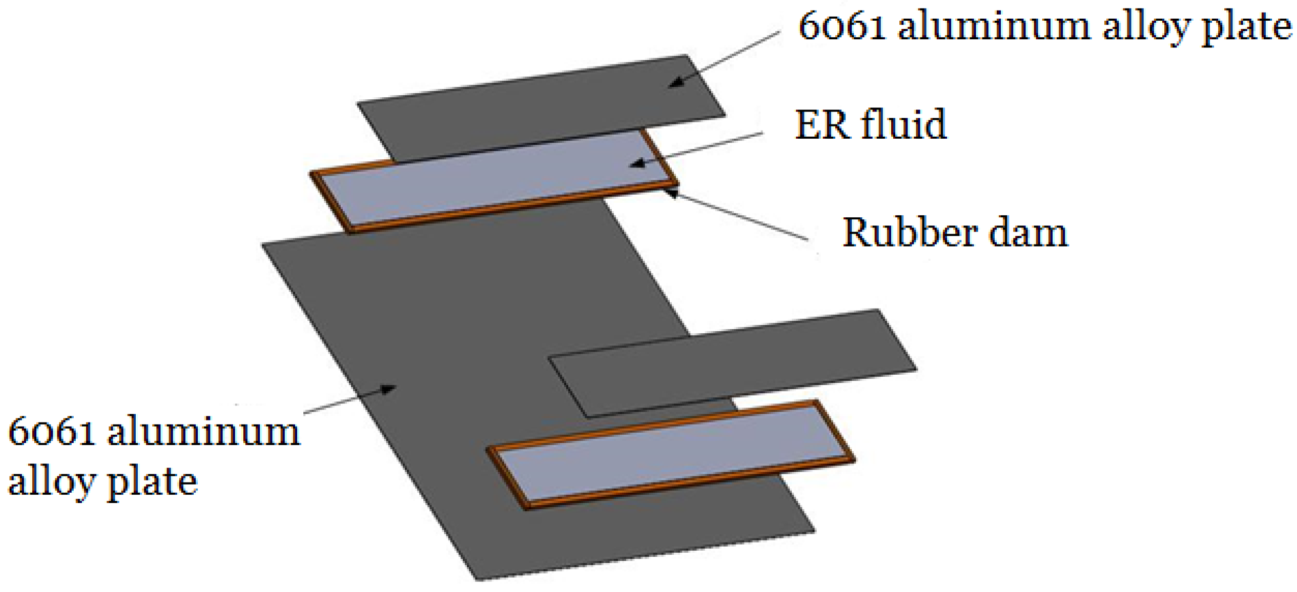
Before equiping a thin plate with ER embedded ATVAs, the vibration’s frequency response of a sandwich ATVA embedded with ER material is studied firstly. The design of the sandwich beam with ER material embedded is as same as our previous reasearch in [16,17]. Figure 1 describes a schematic diagram of a sandwich beam embedded with ER material. The top and bottom plates of sandwich beam are made of aluminum with the thickness of 0.3 mm. The ERF dam has four edges made of rubber and the ER fluid is confined in the volume between the rubber edges and aluminum plates. The ER fluid consists of two components: corn starch and silicon oil (KF-96-20cs), where the weight fraction of the corn-starch suspensions is around 45%–50%. The two aluminum plates also function as the electrodes of the applied electric field. An acrylic pad is used as the rigid spacer for the clamped side. The dimensions and the specifications of the ATVA are described in Table 1.
2.2. Expermental Setup to Measure the Dynamic Response of the ERF Embedded Sandwich Beam
Figure 2 depicts a schematic diagram of the experimental setup for measuring the dynamic characteristics of the sandwich beam with ER fluid embedded. To measure the vibration response of the ERF embedded sandwich beam as the external electric field is applied, the experimental process is similar to our previous researches as follows [16,17].
- (1)
- The left side of the sandwich beam is clamped on top of an electromagnetic vibration shaker (LDS V406) which provides the exciting force to the ERF embedded beam.
- (2)
- A laser displacement sensor (Keyence LC2440; Keyence Corporation, Osaka, Japan) and a non-contacting eddy-current displacement probe (Keyence AH-416; Keyence Corporation, Osaka, Japan) are used to measure the displacements of the input excitation (the clamped side on the shaker) and the free end of the ERF embedded beam.
- (3)
- A high-voltage power amplifier is used to provide the electric field to the ER fluid via the two electrodes of the aluminum plates, which is located on the left side of the ERF embedded beam.
- (4)
- When the different electric fields are applied to the ERF, a dynamic signal analyzer (HP 35665A, Agilent, Santa Clara, CA, USA) is used to analyze the dynamic characteristics of the ERF sandwich beam. The vibration signal is provided to the shaker at the frequency from 0 to 200 Hz to actuate the ERF embedded beam.
- (5)
- The time response signals are captured by the dynamic signal analyzer (HP 35665A). Then, the frequency response is obtained by using fast Fourier transform (FFT) in HP 35665A. The same experimental steps were repeated for the electric field varying from 0 to 2 () in 0.25 () increments.
- (6)
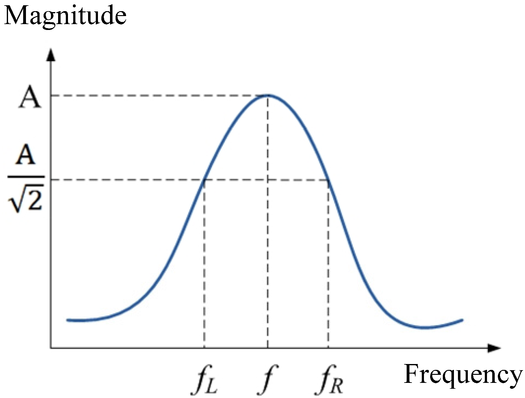
- Figure 2 is the scheme view and diagram to measure the transmissibility of the ERF embedded TVA with the corresponding electric field. Figure 3 shows the transmissibility of the TVA as the different electric field is applied to the ERF. For each electric field applied to the ERF, the damping ratios of ERF can be obtained using the half-power point bandwidth method as follows according to the 1st mode frequency.where the and are the frequencies with the amplitude of (as shown in Figure 4) and is the 1st mode frequency. Table 2 describes damping ratios of the ERF for each electric field obtained by the half-power point bandwidth method.
- (7)
- According to the 1st mode frequency of the ERF embedded sandwich beam in Figure 3, the equivalent shear modulus of the ERF can be obtained by using the goal driven optimization method in ANSYS Workbench. In the simulation, the goal is to find the optimal shear modulus of ERF to make the simulated 1st mode frequency of the ERFATVA be consistent with the actual value obtained by the experiments. Therefore, the damping ratio and shear modulus of the ERF are used in the ANSYS model.
3. Design and Analysis of the ERF Embedded ATVA for a Plate Structure
3.1. Governing Equations of the ERF Embedded Beam
Before we investigate vibration control of a thin plate using the self-designed ERF embedded ATVA, the characteristics of the sandwich plate with ER material embedded between two plates should be studied first. The physical principle of electrorheological TVA is to change the material properties (both stiffness and damping) of ERF via the controllable electric field; then, we can actively shift the resonant frequencies of the structure away from excitation frequencies to attenuate the vibration due to the varying properties of the TVA embedded ERF. In the range of the applied electric field used in this study, the mode shape of the tuned structure should remain similar shape because of the far apart modal frequencies for different modes. Consider a sandwich plate with ER material embedded between two face plates as shown in Figure 5, the governing equations for this structure were derived using principle of minimum total potential energy and written as the following [14].
Since we are interested in the response of the system when it is subjected to single harmonic excitation, the steady state response will be in the same excitation frequency. Under harmonic excitation, the shear stiffness of the ER fluid can be expressed as a complex variable which is function of the applied electric field. The complex moduli of ER fluid contain two parts: storage modulus and loss modulus. The damping of the ER fluid should relate closely to the loss modulus. Of course, this structural damping can be converted into equivalent viscous damping if necessary. Because the main focus of this work is on the development of control algorithm, further theoretical formulation in this regard is not pursued.
3.2. Simulation Study to Obtain a Suitable Width of the ERF Embedded ATVA for a Plate Using ANSYS
In the present work, a 1-mm-thick 6061 aluminum alloy plate (shown in Figure 6) is used for studying the semi-active vibration control. Figure 6 shows that two ERF embedded ATVA are attached to the plate with the dimension of 200 × 200 × 0.5 (mm). In this case study, the width of the ERF embedded beam is limited in the range of 20–36 mm. To obtain the suitable width of the ERF embedded ATVA for this plate structure, the ANSYS software is used to simulate the vibration’s frequency response for the different electric fields applied to the ERF.
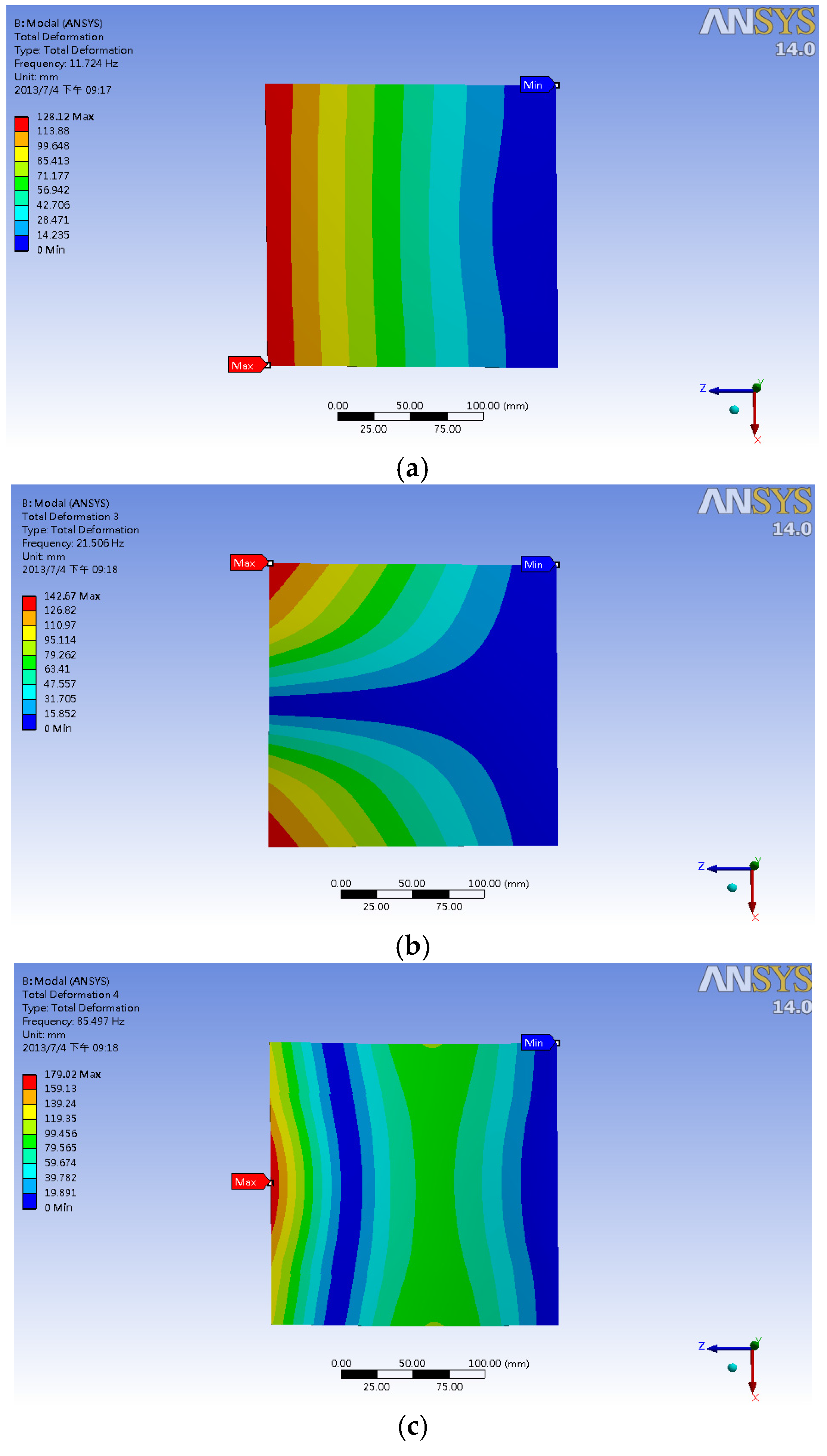
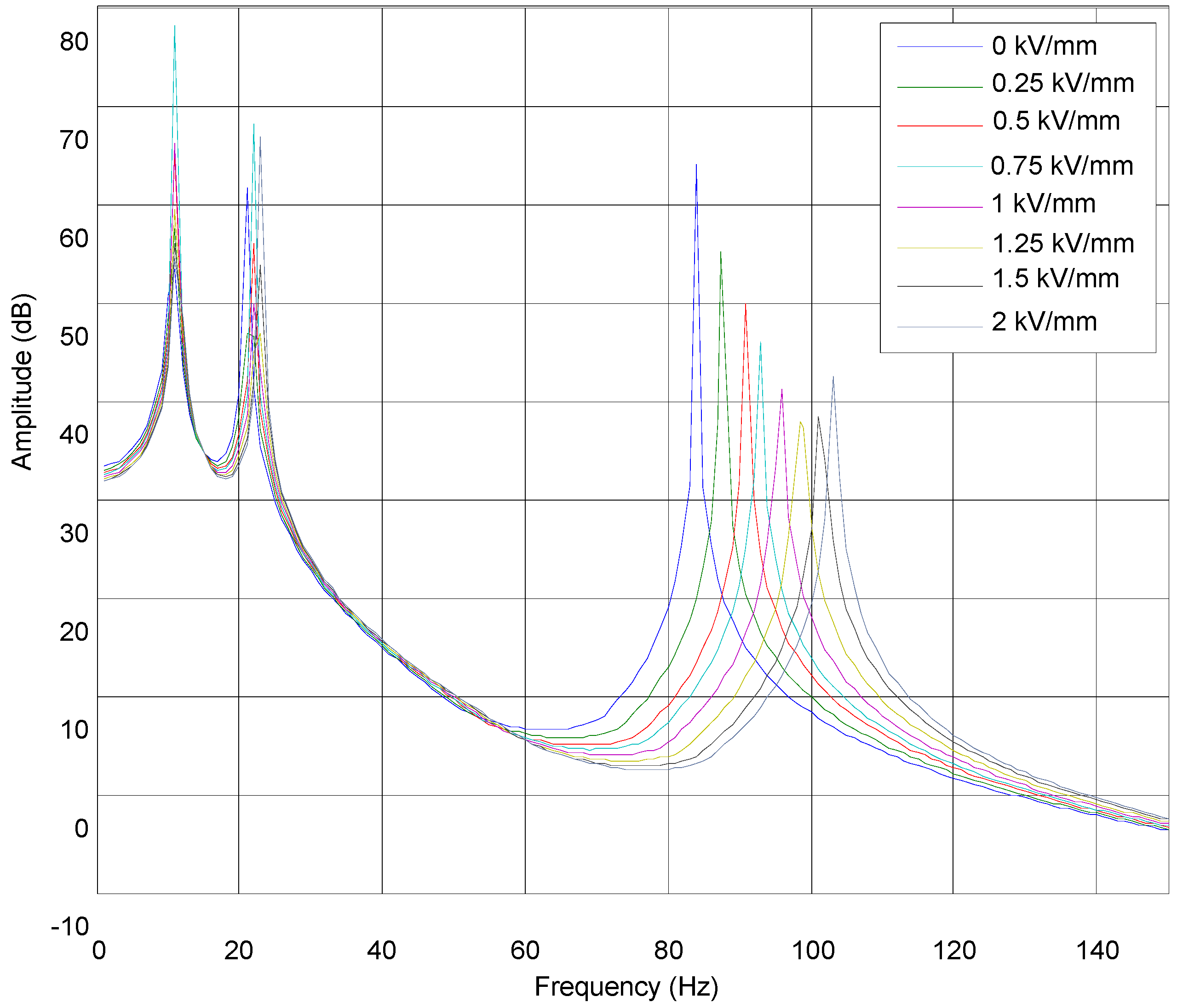
In this simulation study, the material properties of the ATVA is set up according to the viscous coefficients and the equivalent shear modulus obtained by the previous experimental results in Section 2.1. Figure 7 shows the first three vibration mode shapes of this plate structure with the ERF embedded ATVA obtained by using ANSYS software. When the electric fields of 0 kV/mm and 2 kV/mm are applied to the ERF embedded ATVA, respectively, we can obtain the frequency shifts of this structure equipped with the ERF embedded ATVA at the first three vibration modes. To obtain the suitable width of the ERF embedded ATVA and its width is changed from 20 to 36 mm in the simulation studies. With the ERF embedded ATVA whose width is between 20 and 36 mm, Table 2 shows the resulting frequency shifts at the vibration models of this structure as the electric field is changed from 0 to 2 kV/mm. The simulation results show that the ATVA can change the resonant frequencies of the main structure as the different external electric field is applied. Therefore, the vibration of the main structure can be controlled if a suitable electric field is applied to the ERF embedded ATVA. Based on the simulation results in Table 2, to obtain the superior performance in suppressing vibration for the ATVA, the ATVA’s width is chosen as 36 mm in the following experimental setup, because the summation of the frequency shifts at the first three mode is maximal as w = 36 mm. With using the ANSYS software to simulate the vibration’s frequency response for the different applied electric field to the ERF, Figure 8 shows the frequency responses of the plate structure with the ERF embedded ATVA (w = 36) as different electric fields are applied (0 kV/mm–2 kV/mm) and Table 3 describes the Frequency shifts at the vibration models of this structure equipped with the ERF embedded ATVA (with the width from 20 to 36 mm) for the electric field changed from 0 to 2 kV/mm. To validate the simulation result, the experimental setup for frequency measurements is presented in the following section.
3.3. Experimental Validations
Figure 9a presents the schematic diagram of the experimental setup for measuring the dynamic properties of the plate structure with the ERF embedded ATVA. The plate was clamped with the aluminum alloy fixture located on a cast iron platform and the impulse technique was employed in the measurement. The input excitation was provided by an impact hammer (PCB 084A17) and the induced vibration was measured by a non-contacting eddy-current displacement probe (Keyence AH-416). Both input and output signals were processed by a dynamic spectrum analyzer (Novian-N94) and the corresponding frequency response was obtained. To validate the simulation results, there are 36 points (as shown in Figure 9b) located at the structure for the experiments to obtain its dynamic properties. The eddy-current displacement probe is located at the 26th point and the impact hammer hits the other 35 points to obtain the frequency responses. According to the experimental results, the mode shapes of the first three modes are obtained as shown in Figure 10. Comparing the mode shapes of simulation results (Figure 7) with the experimental outcome (Figure 10), we found that the experimental data were consistent with simulation results.
Moreover, the experimental data (in Figure 10) can help us to determine the suitable points for the following case studies, because the displacement probe and the stimulating input should not be located at vibration nodes to improve the precision of the frequency response. Figure 11 presents the experimental setup to measure the dynamic properties of the structure with different external electrical fields. For measuring the vibration mode of the structure, an electromagnetic shaker is used to stimulate the structure as shown in Figure 11. During measurement, a random excitation signal was generated by the dynamic signal analyzer and further amplified by the power amplifier to drive the shaker. One eddy-current displacement probe was used to measure the input and the other one was used to measure the output displacement with the largest amplitude at each vibration mode. Table 4, Table 5 and Table 6 show the experimental results for the first three modes of this structure as different external electric fields (0 kV/mm–2 kV/mm) were applied. Based on the experimental data in Table 4, the damping ratios of the ATVA can be obtained.
According to the experimental results in Table 4, the first mode’s frequency is changed from 11.625 to 13.375 Hz when the external electric field varies from 0 to 2 kV/mm; the variation of the frequency is 15.05% and the variation of the amplitude is almost 37.01% (from 16.1 dB to 10.14 dB). In Table 5, the second mode’s frequency is changed from 18.375 to 18.5 Hz when the external electric field varies from 0 to 2 kV/mm; the variation of the frequency is only 0.68%. Because the amplitude at E = 0 kV/mm is 17.87 dB and the amplitude at E = 1 kV/mm is 12.42 dB, the maximal variation of the amplitude is almost 30.49% for the second mode. In Table 6, the third-mode frequency is changed from 77 to 78.625 Hz when the external electric field varies from 0 to 2 (kV/mm); the variation of the frequency is only 2.1%. Because the amplitude of E = 0 kV/mm is 20.79 dB and the amplitude of E = 1 kV/mm is 17.41 dB, the maximal variation of the amplitude is almost 16.25% for the second mode. With observing the relation between the external electric field and the damping coefficient of the ATVA, we found that the dynamic properties of the ERF embedded ATVA are very nonlinear. Therefore, the semi-active controller should be adaptive to tune its damping coefficients properly according to the external vibration with different frequency. Therefore, a fuzzy modeling and experimental validations of ERF-based ATVA from stationary random vibrations of thin plates are presented in the following section.
4. Semi-Active Vibration Control of the Thin Plate Using the ERF Embedded ATVA
4.1. Experimental Setup for the Thin Plate with Varying Harmonic Vibrations
In our previous research, we have designed a semi-active controller for the cantilever beam equipped with the ERF embedded ATVA for the vibration at specified frequencies [17]. However, the thin plate’s vibration mode shape is different from the cantilever beam. Figure 10 shows the plate’s vibration modes, where the locations with the maximum displacement vary with the vibration modes. As shown in Figure 10a, the first mode shape of the plate is similar to the one of the cantilever beam; the maximum displacement appears at the free end. Therefore, to measure the vibration of the first mode, the displacement sensor can be located at the edge of the free end.
However, as shown in Figure 10b, the maximum displacement of the second mode appears at the both side of the free end. If we need to measure the vibrations of both the first and second modes, the middle point of the free end is not a good choice to locate the displacement sensor. Even though the middle point of the free end can measure the vibration of the first mode, this location is not sensitive to the vibration of the second mode. As a result, to measure the vibration of the second mode, the displacement sensor should be located at both sides of the free end. With observing the mode shape of the third mode in Figure 10c, we found that the location with the maximum displacement appears at the middle point of the free end for the third vibration mode. Therefore, to measure the vibration of the third mode, we need to locate the sensor at the middle point to obtain the best sensitivity to the vibrations. Obviously, the choice of displacement sensor’s location of the third mode is in conflict with the ones of the first and second modes.
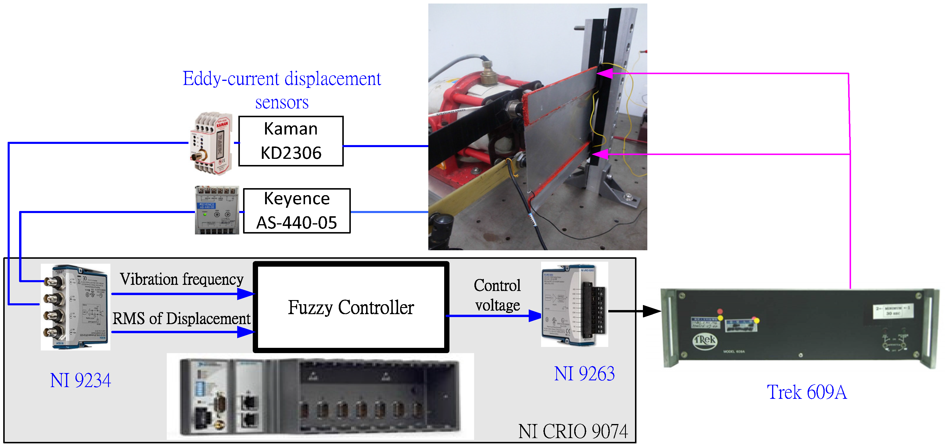
With consideration of measuring the multi-mode vibrations, we proposed to use two displacement sensors to measure the response of the plate for the different vibration modes. On the one hand, an eddy-current displacement sensor is located at the upper side of the free end to measure the vibrations of the first and second modes; on the other hand, the other displacement sensor is located at the middle of the free end to measure the vibration of the third mode. Figure 12 shows the schematic diagram of semi-active vibration control architecture for the ERF embedded ATVA. Two eddy-current displacement sensors are located at the middle and the upper of the free end to measure the vibration of the plate; the embedded controller (cRIO-9074) is used to implement the real-time control system. The analog input module (NI 9234) is employed to capture the feedback signals of the displacement sensors and the analog output module (NI 9263) is used to provide the analog signal according to the proposed semi-active vibration controller. Then, the output signal of NI 9263 is amplified via the high-voltage power amplifier (Trek 609A) to produce the required electric field to the ERF material.
In this paper, we proposed a type-2 fuzzy controller, which has two inputs and one output as shown in Figure 12. The first input is the vibration frequency, which is obtained by fast-Fourier transformation (FFT) of the measured displacement signals; the second input is the root-mean-square value (RMS) of the displacement of the plate’s free end. The RMS value of displacements and the vibration frequency are fed back to a fuzzy controller, which produces the required output voltage to the high-voltage power amplifier. Consequently, we will discuss how to design the type-2 fuzzy controller to establish the input–output mapping between the vibration signal and the required electric field of ERF material.
4.2. Semi-Active Vibration Control Using the Interval Type-2 Fuzzy
The fuzzy rules of semi-active control are usually obtained by using the expert database or the relation between input and output from experimental results [17]. In this paper, to establish the fuzzy controller’s rule base at the different frequencies, we measure the vibration response of the structure with the ERF ATVA with different applied electric field at different frequency; then, according to the experimental results, the optimal electric field at different frequency is recorded to establish the expert database of the fuzzy rules.
In all experiments, a sinusoidal signal is input to the shaker’s amplifier at follows.
where A is the amplitude of the input signal and f is the frequency of the sinusoidal signal.
The signal is amplified to drive the electromagnetic vibration shaker and then the shaker provides the stimulating vibration to the structure. Consequently, the electric field of the ATVA is tuned at different levels of 0–2 (kV/mm) to perform the vibration experiments; the vibration displacement of the structure is measured by the eddy-current displacement sensors and recorded by the NI CRIO 9074 simultaneously.
For an external vibration produced by the shaker with the sinusoidal signals of different amplitudes at 8–80 Hz, Table 7 and Table 8 record the frequency responses of this smart structure with respect to the different external electric field applied to ERF, where the vibration displacement is computed by using the root mean square (RMS) value of the eddy-current sensor’s output. In these tables, the smaller RMS value of displacement sensor implies that the ATVA has better ability of absorbing vibration. In the same column, the bold-face type number shows that the structure has the smaller vibration with suffering the same external vibration. For example, check the first column of Table 7, if A = 50 mV and f = 8 Hz, the best choice for the controller is E = 1.5 (kV/mm), because the vibration displacement of the structure is the smallest with this electric field of E = 1.5 kV/mm. For the first mode of vibration with the frequency range of 8–17 Hz, the experimental results show that the ATVA has the better performance with the larger external electric field. These experimental results imply that the ATVA has better ability of absorbing vibration if its viscous coefficient is larger for the frequencies at the first vibration mode. However, for the second mode of vibration, the optimal external electric field is different from the first mode. With the exception of the vibration at the frequency of 21 Hz, the ATVA has better ability of absorbing vibration with a smaller electric field at the frequencies of 19, 23 and 25 Hz. With the vibration at the frequency of 21 Hz, the ATVA with the electric field of E = 1 kV/mm has better ability of absorbing vibration than the others.
In addition, for the third vibration mode, the ability of absorbing vibration for the ATVA is changed again. According to the experimental results in Table 8, with the exception of the vibration at the frequency of 88 Hz, the ATVA has better ability of absorbing vibration with the electric field of E = 1.5 kV/mm for the vibration with the frequency of 74, 76, and 78 Hz. From the experimental results in Table 7 and Table 8, it is obvious that the relation between the optimal electric field and the vibration frequency of the smart structure is nonlinear. In some cases, the amplitude of vibration is also influence the performance of the proposed ATVA. Therefore, we need to design a semi-active vibration controller to produce the optimal electric field with respect to the vibration. Because of the nonlinear relation between the optimal electric field and the ability of absorbing vibration, a type-2 fuzzy controller is proposed to establish the input–output mapping according to the experimental results.
Type-2 Fuzzy Controller Design for ATVA
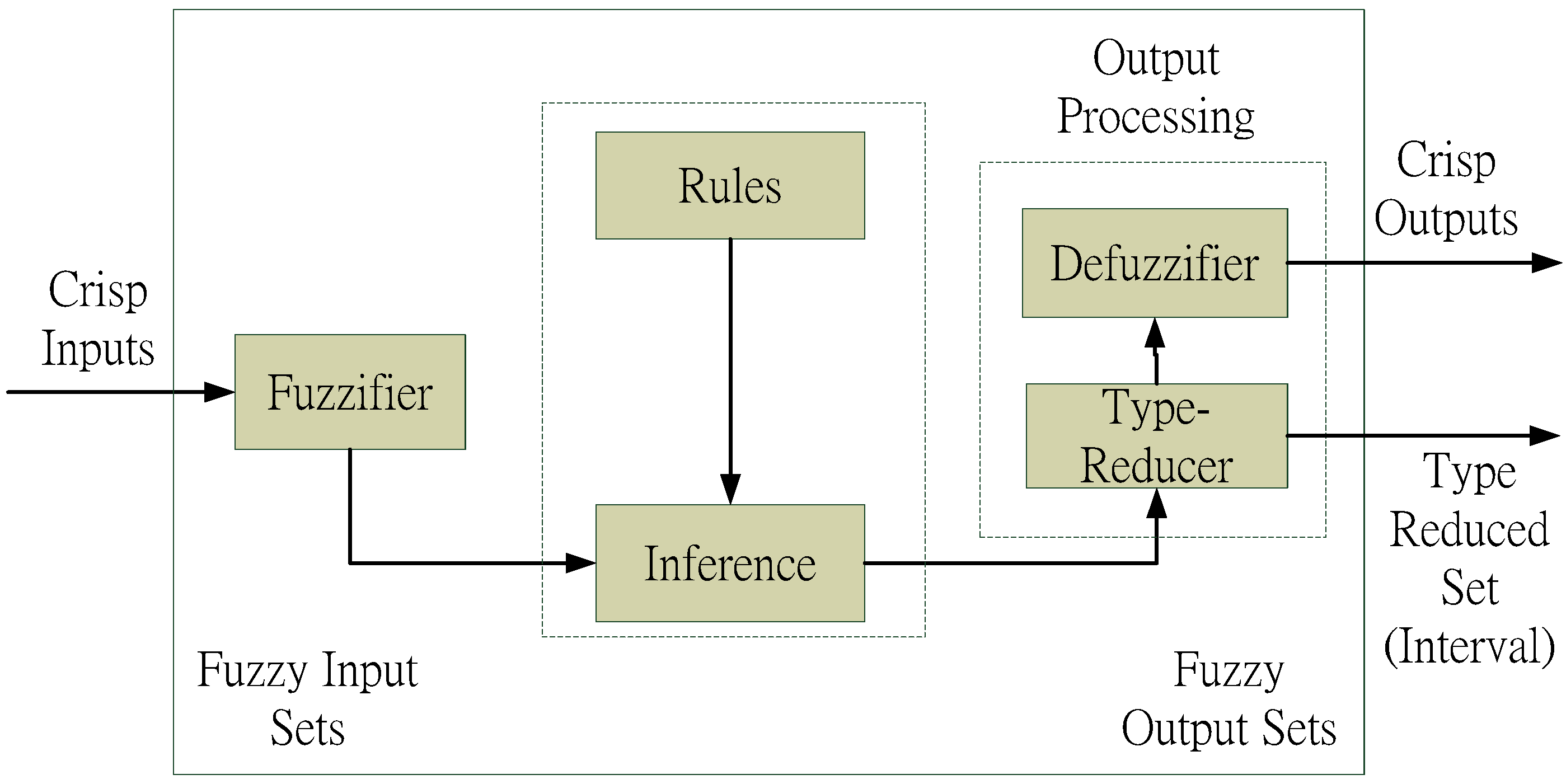
An interval type-2 Fuzzy Logic System (FLS) is studied for vibration control in the presence of system modeling uncertainties [17]. The type-2 fuzzy system has a similar structure with type-1 fuzzy, but the major difference is that the rule base has antecedents and consequents using type-2 fuzzy sets. First, the first mode of vibration is considered, a Gaussian function with a known standard deviation and a uniform weighting were used to represent a footprint of uncertainty as shaded in Figure 13. Because of using such a uniform weighting, it is usually called an interval type-2 fuzzy set (IT2FS) [72]. For the IT2FS, a type-reducer is needed to convert to a type-1 fuzzy set before defuzzification is carried out as shown in Figure 14. To obtain the output of the IT2FS, we need two fuzzy rule tables; however, the same fuzzy rule table is used in this case as shown in Table 9. After obtaining the inference output, the type-reducer and defuzzifier are used to obtain the input–output relation and the two signals (Drms, f) were fed back to the proposed fuzzy controller.
For type-2 fuzzy system, Figure 15 shows the inference operation to obtain the output by using the following equations. After obtaining the inference output, we used the type-reducer and defuzzifier to obtain the input–output relation as shown in Figure 16.
where N is the number of the inputs.
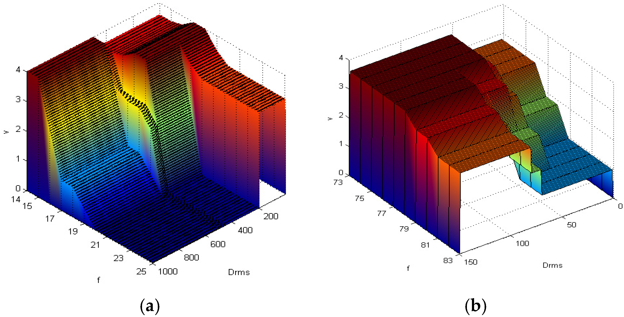
As shown in Figure 16, we can obtain the optimal voltage by the input–output lookup relation of the fuzzy controller. Then, the proposed semi-active vibration controller generates the required voltage through the high voltage power amplifier to actuate the ATVA for absorbing vibration. According to Table 8 and Table 9, the input–output relation of the type-2 fuzzy controller is shown in Figure 17 for the second and third modes. It is obvious that the fuzzy rules are different from the fuzzy rule of the first vibration mode. Therefore, for the different vibration mode, we should tune the electric field according to the specified rules in Figure 16 and Figure 17. Therefore, the fuzzy controller should have the adaptive tuning ability to obtain the superior performance for the vibration with varying frequency. Consequently, we proposed a type-2 fuzzy controller with a switching-mode rule as follows.
4.3. Semi-Active Vibration Controller with a Switching-Mode Rule for ATVA
Because of the nonlinear dynamic properties of the ERF embedded ATVA with response to the vibration at different frequencies, a semi-active vibration control with a switching-mode rule is proposed to determine the optimal electric field for the ATVA. There are two reasons why the switching action is necessary. The first reason is that the location with the maximum displacement may vary for the different vibration mode. Therefore, in Section 4.1, we proposed to use two displacement sensors to better measure the response of the plate for the different vibration mode. The second reason is that the electric field of the ATVA should be adaptively tuned for the different vibration mode (as shown in Figure 16 and Figure 17) to obtain the superior ability of absorbing vibration for the ATVA. Therefore, we proposed a fuzzy controller of the ATVA for attenuating the undesired vibration by using the frequency-dependent control strategy [7].
Figure 18 shows the proposed switching algorithm of the fuzzy controller according to the frequency response to tune the electric field adaptively and Figure 19 is the real-time embedded code for the NI CRIO 9074. First, we established the type-2 fuzzy controllers for the three vibration modes using the look-up tables as shown in Figure 16 and Figure 17. Second, the displacements of the structure are captured by the CRIO 9074. Third, the vibration frequency is obtained from the FFT of the displacements. Then, the real-time program uses the resulting frequency to distinguish which the vibration mode is and switch the input to the suitable controller to produce the control voltage.
5. Experimental Results and Discussion
5.1. Case I: External Vibration at the Specified Frequency
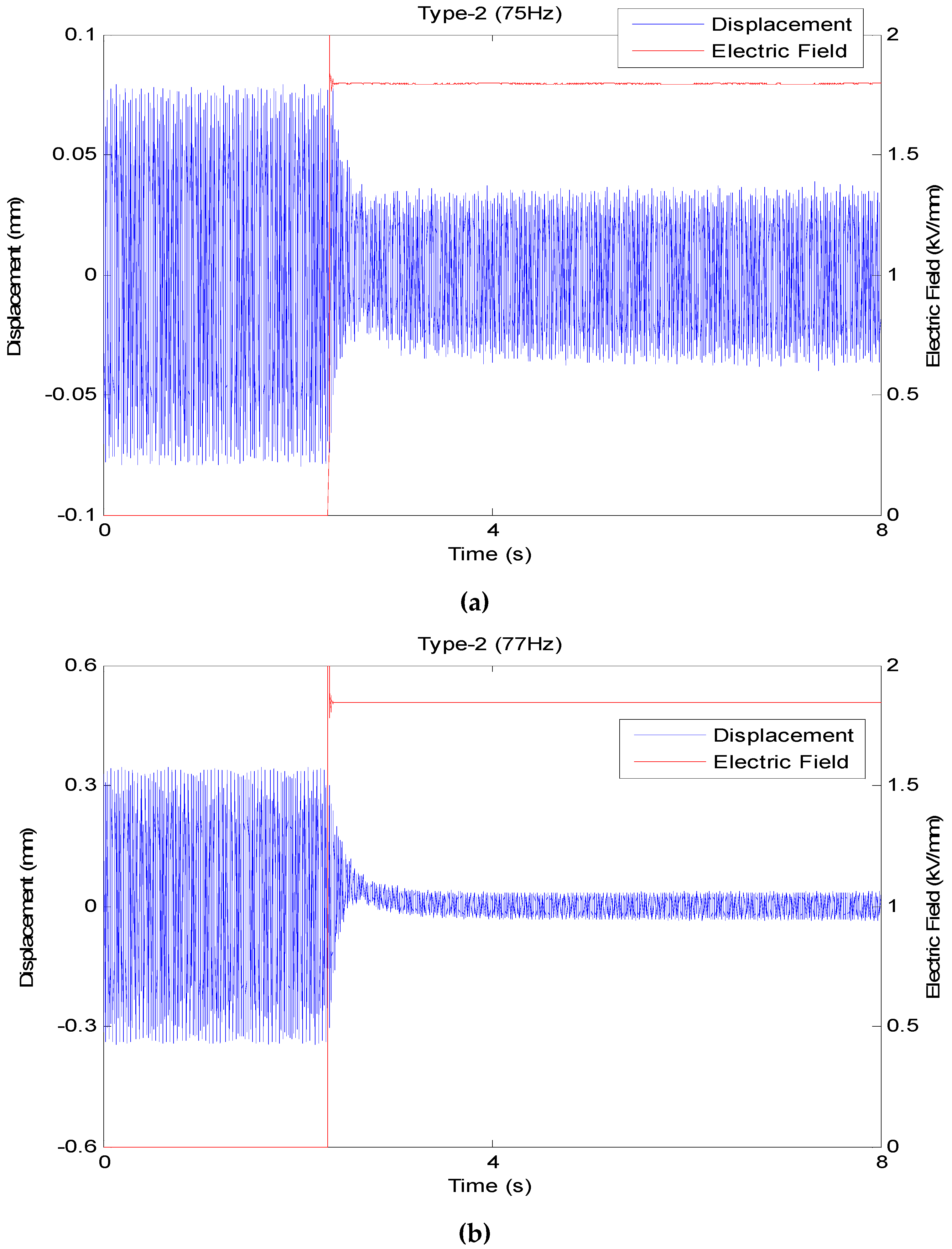
The excitation signals at the frequencies from 8 to 78 Hz are inputted to the shaker to vibrate the structure to validate the proposed semi-active controller. To compare the performance of the proposed controller for different vibration modes, we designed five case studies to investigate the vibration absorbing ability of the ATVA. Figure 20, Figure 21 and Figure 22 compare the vibration responses with no control with the ones of the proposed controller at the frequency of 8, 10, 18, 20, 75 and 77 Hz, where the fuzzy controller is turned on at t = 2.5 s. The vibration reduction rate (VRR) is defined as follows.
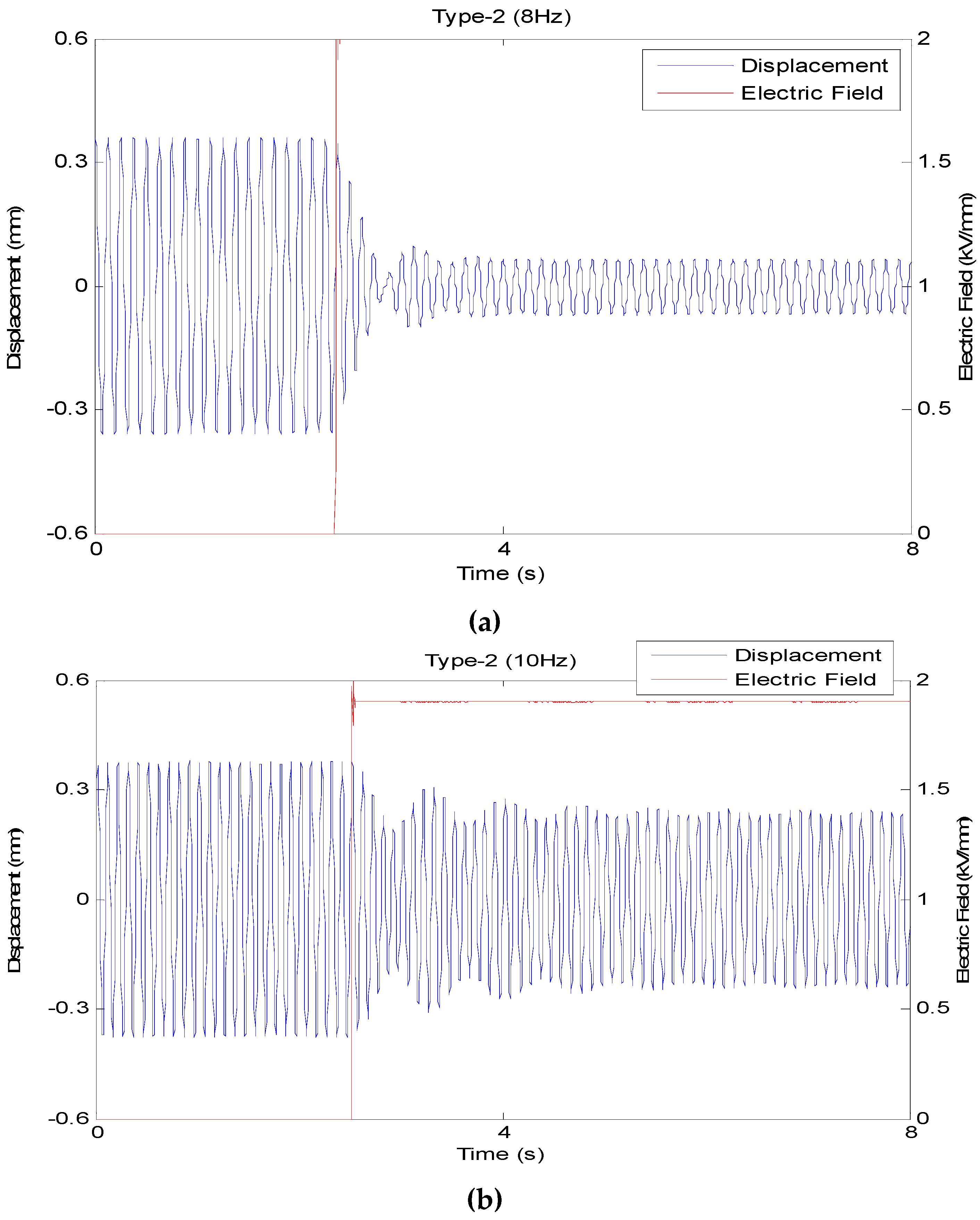
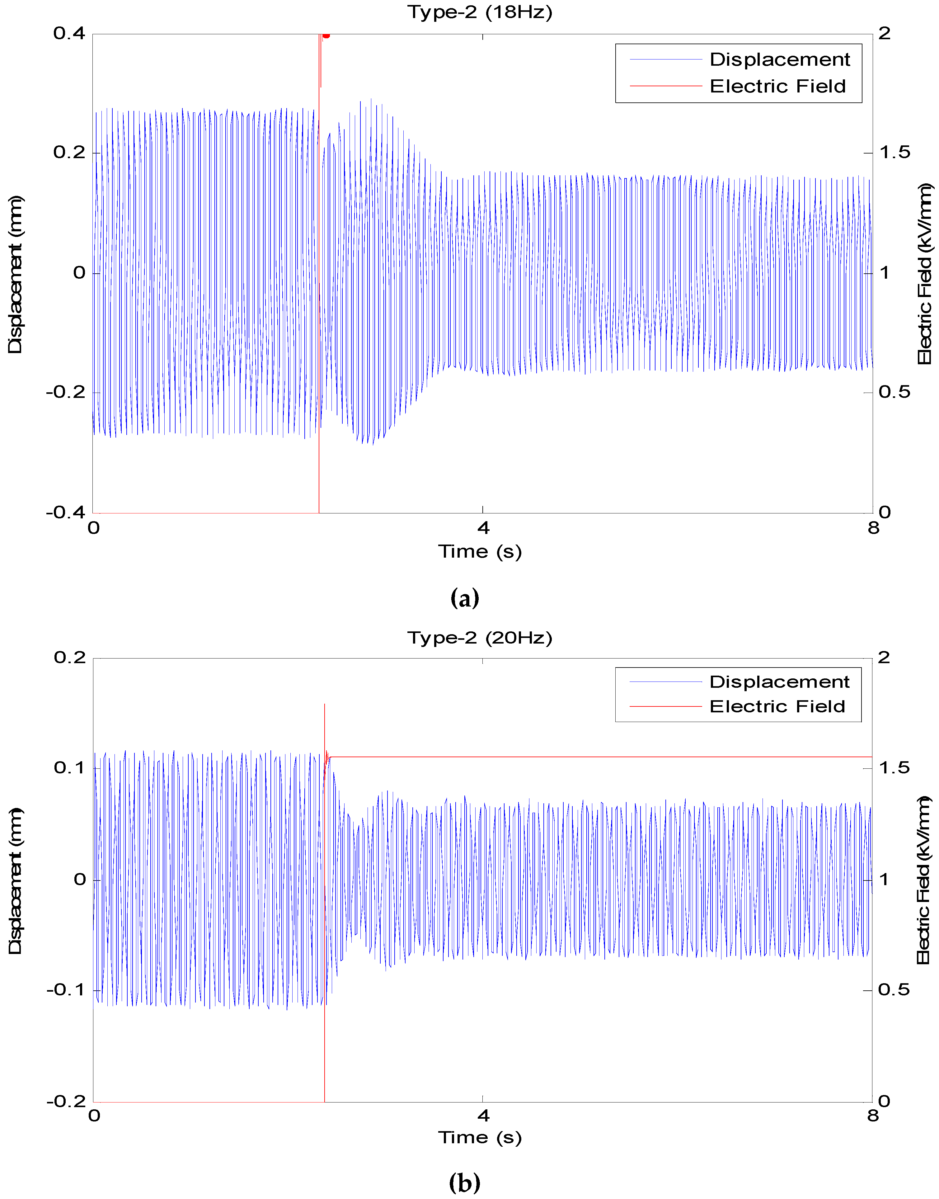
With the external vibration at the frequency close to the first vibration mode of the structure, Figure 20 shows that the type-2 fuzzy controller has better vibration-reduction ability with the frequency of 8 Hz, whose VRR is 81.5%. The VRR with the frequency of 8 Hz is better than the one with the frequency of 10 Hz, whose reduction rate is 36.1%. When the external vibration’s frequency is close to the second vibration mode, Figure 21 shows that the proposed controller has the VRR of about 40%. With the external vibration at the frequency close to the third mode of the structure, Figure 22 shows that the proposed type-2 fuzzy controller has the best performance at the frequency of 77 Hz, whose VRR is about 89%. Table 10 summarizes the results at the frequencies of 8, 10, 18, 20, 75 and 77 Hz using the proposed controller, the experimental results is compared with the ones using type-1 fuzzy controller [16] in the previous studies. According to the experimental results, the proposed type-2 fuzzy controller has better performance of absorbing vibration than the type-1 fuzzy control.
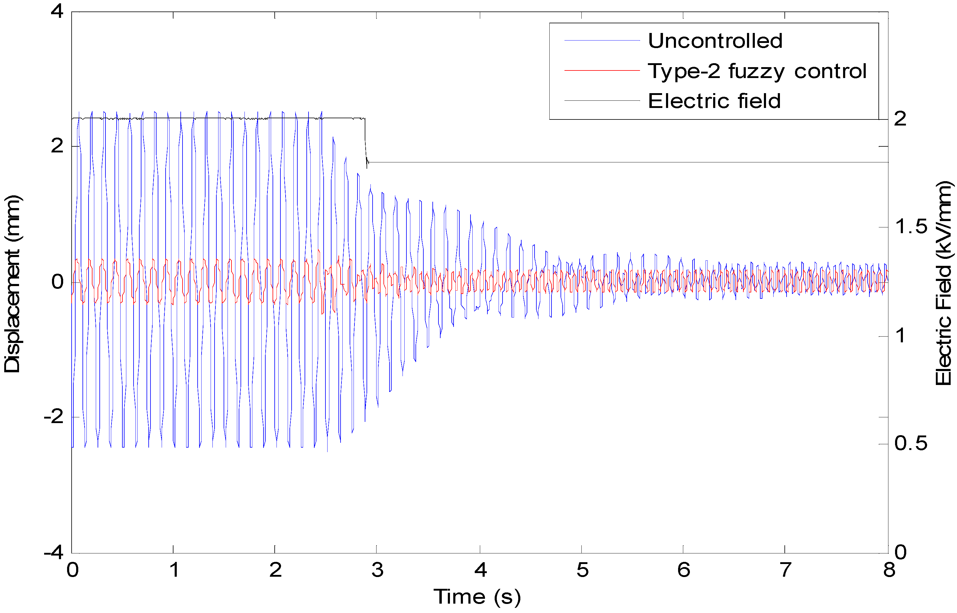
5.2. Case II: External Vibration with the Varying Frequency
To test the applicability of the proposed fuzzy controller for the external vibration with the varying frequency, an external excitation of 8 Hz was applied to the main structure at t = 0 s. Then, we changed the frequency of the excitation from 8 to 16 Hz at t = 3 s. Figure 23 shows the measured time response of the structure’s displacement. Figure 23 validates that the proposed fuzzy controller has the adaptive ability to suppress vibration efficiently and rapidly, even if the frequency of external vibration is changed. Figure 23 shows that the VRR of the proposed control at the frequency of 8 Hz is almost 86.5% with the electric field output of 2 kV/mm, which is consistent with the previous result in Figure 20. The electric field output of 1.8 kV/mm is obtained by using the proposed controller and the VRR of 16 Hz is almost 29.4%. Therefore, the experimental result shows that the proposed controller validates the vibration reduction ability for the external vibration with the two frequencies of 8 and 16 Hz. From the above experimental results, we found the fact that the proposed ATVA has the superior ability of absorbing vibration for this plate at the first and third vibration modes (8 Hz and 77 Hz). For the second mode, the VRR of the ATVA is reduced from 81.5% (for the first mode) to 40.9%. Except for the vibration frequency of 8 Hz, the proposed type-2 fuzzy controller has better VRR than the type-1 fuzzy control.
6. Conclusions
A semi-active fuzzy controller for using a self-designed actively tunable vibration absorbers (ATVA) is presented to suppress vibration of a thin plate. The ATVA is made of a sandwich hollow structure embedded with the electrorheological fluid (ERF). To implement the proposed fuzzy controller, the fuzzy rules are determined based on the experimental database for the specified frequencies and amplitudes. Because there are uncertainties in modeling of the nonlinear characteristics of ERF TVA, the proposed type-2 fuzzy controller shows better performance than the type-1 fuzzy controller. To confirm the consistency of the simulation and experimental results, the proposed controllers are implemented in the real-time embedded controller (NI CompactRIO 9074; National Instruments Corporation, Austin, TX, USA). The experimental results show that the proposed ATVA has the superior ability of absorbing vibration for this plate at the first and third vibration modes (8 Hz and 77 Hz). The vibration reduction rate (VRR) of the plate structure using the proposed ATVA is 81.5% for the first vibration mode. For the second vibration model, the VRR of the plate structure using the proposed ATVA is 40.9%. The proposed type-2 fuzzy controller has the best performance at the frequency of 77 Hz, whose VRR is about 89%. The experimental results verified the effectiveness of the proposed semi-active vibration controller using the interval type-2 fuzzy system.
Acknowledgments
The authors would like to thank the Ministry of Science and Technology of the Republic of China, Taiwan for financially/partially supporting this research under Contract No. MOST 104-2221-E-027-026 and MOST 105-2221-E-027-041. The authors also thanks the partially fund supporting from Project for developing the model university of science and technology.
Author Contributions
Chih-Jer Lin conceived and designed the experiments; Chun-Ying Lee contributed reagents/materials/analysis tools; Ying Liu performed the experiments and analyzed the data; and Chih-Jer Lin wrote the paper.
Conflicts of Interest
The authors declare no conflict of interest.
References
- Carlson, J.D.; Catanzarite, D.M.; St. Clair, K.A. Commercial magneto-rheological fluid device. In Proceedings of the 5th International Conference ER Fluids, MR Fluids and Associated Technology, Sheffield, UK, 10–14 July 1995; pp. 20–28. [Google Scholar]
- Giurgiutiu, V. Review of Smart-Materials Actuation Solutions for Aeroelastic and Vibration Control. J. Intell. Mater. Syst. Struct. 2000, 11, 525–544. [Google Scholar] [CrossRef]
- Valliappan, S.; Qi, K. Review of seismic vibration control using ‘smart materials’. Struct. Eng. Mech. 2001, 11, 617–636. [Google Scholar] [CrossRef]
- Vautier, B.J.G.; Moheimani, S.O.R. Vibration reduction of resonant structures using charge controlled piezoelectric actuators. Electron. Lett. 2003, 39, 1036–1038. [Google Scholar] [CrossRef]
- Moheimani, S.O.R.; Vautier, B.J.G. Resonant control of structural vibration using charge-driven piezoelectric actuators. IEEE Trans. Control Syst. Tech. 2005, 13, 1021–1035. [Google Scholar] [CrossRef]
- Rodriguez-Fortun, J.M.; Orus, J.; Alfonso, J.; Gimeno, F.B.; Jose, A.; Castellanos, J.A. Flatness-Based Active Vibration Control for Piezoelectric Actuators. IEEE/ASME Trans. Mech. 2013, 18, 221–229. [Google Scholar] [CrossRef]
- Steiger, K.; Mokrý, P. Finite element analysis of the macro fiber composite actuator: Macroscopic elastic and piezoelectric properties and active control thereof by means of negative capacitance shunt circuit. Smart Mater. Struct. 2015, 24, 025026. [Google Scholar] [CrossRef]
- Zhang, S.; Yan, B.; Luo, Y.; Miao, W.; Xu, M. An Enhanced Piezoelectric Vibration Energy Harvesting System with Macro Fiber Composite. Shock Vib. 2015, 2015, 916870. [Google Scholar] [CrossRef]
- Beek, T.V.; Pluk, K.; Jansen, H.; Lomonova, E. Optimisation and measurement of eddy current damping in a passive tuned mass damper. IET Electr. Power Appl. 2016, 10, 641–648. [Google Scholar] [CrossRef]
- Scheidler, J.J.; Asnani, V.M.; Dapino, M.J. Dynamically tuned magnetostrictive spring with electrically controlled stiffness. Smart Mater. Struct. 2016, 25, 035007. [Google Scholar] [CrossRef]
- Olabi, A.G.; Grunwald, A. Design and application of magnetorheological fluid. Mater. Des. 2007, 28, 2658–2664. [Google Scholar] [CrossRef]
- Weber, F.; Maslanka, M. Frequency and damping adaptation of a TMD with controlled MR Damper. Smart Mater. Struct. 2012, 21, 055011. [Google Scholar] [CrossRef]
- Lin, C.J.; Yau, H.T.; Lee, C.Y.; Tung, K.H. System Identification and Semiactive Control of a Squeeze-Mode Magnetorheological Damper. IEEE/ASME Trans. Mech. 2013, 18, 1691–1701. [Google Scholar] [CrossRef]
- Lee, C.Y.; Cheng, C.C. Dynamic Characteristics of Sandwich Beam with Embedded Electro-Rheological Fluid. J. Intell. Mater. Syst. Struct. 1998, 9, 60–68. [Google Scholar] [CrossRef]
- Sun, Y.; Thomas, M. Control of torsional rotor vibrations using an electrorheological fluid dynamic absorber. J. Vib. Control 2011, 17, 1253–1264. [Google Scholar] [CrossRef]
- Lin, C.J.; Lee, C.Y.; Cheng, C.H.; Chen, G.F. Vibration Control of a Cantilever Beam Using a Tunable Vibration Absorber Embedded with ER Fluids. Int. J. Aerosp. Ind. Mechatron. Manuf. Eng. 2013, 7, 1412–1418. [Google Scholar]
- Lin, C.J.; Lee, C.Y.; Liu, Y.; Cheng, C.H. Interval Type-2 Fuzzy Vibration Control of a ERF Embedded Smart Structure. Int. Sci. Index Mechan. Mechatron. Eng. 2014, 8, 1215–1221. [Google Scholar]
- Song, G.; Ma, N.; Li, H.-N. Applications of shape memory alloys in civil structures. Eng. Struct. 2006, 28, 1266–1274. [Google Scholar] [CrossRef]
- Lee, C.Y.; Chen, C.C.; Yang, T.H.; Lin, C.J. Structural vibration control using a tunable hybrid shape memory material vibration absorber. J. Intell. Mater. Syst. Struct. 2012, 23, 1725–1734. [Google Scholar] [CrossRef]
- Damanpack, A.R.; Bodaghi, M.; Aghdam, M.M.; Shakeri, M. On the vibration control capability of shape memory alloy composite beams. Compos. Struct. 2014, 110, 325–334. [Google Scholar] [CrossRef]
- Lee, C.Y.; Pai, C.A. Design and implementation of tunable multi-degree-of-freedom vibration absorber made of hybrid shape memory helical springs. J. Intell. Mater. Syst. Struct. 2016, 27, 1047–1060. [Google Scholar] [CrossRef]
- Soltani, P.; Kerschen, G.; Tondreau, G.; Deraemaeker, A. Piezoelectric vibration damping using resonant shunt circuits: An exact solution. Smart Mater. Struct. 2014, 23, 125014. [Google Scholar] [CrossRef]
- Guo, K.; Jiang, J. Independent modal resonant shunt for multimode vibration control of a truss-cored sandwich panel. Int. J. Dyn. Control 2014, 2, 326–334. [Google Scholar] [CrossRef]
- Yan, B.; Zhang, X.; Luo, Y.; Zhang, Z.; Xie, S.; Zhang, Y. Negative impedance shunted electromagnetic absorber for broadband absorbing: Experimental investigation. Smart Mater. Struct. 2014, 23, 125044. [Google Scholar] [CrossRef]
- Qureshi, E.M.; Shen, X.; Chen, J. Vibration control laws via shunted piezoelectric transducers: A review. Int. J. Aeronaut. Space Sci. 2014, 15, 1–19. [Google Scholar] [CrossRef]
- Yan, B.; Luo, Y.; Zhang, X. Structural multimode vibration absorbing with electromagnetic shunt damping. J. Vib. Control 2016, 22, 1604–1617. [Google Scholar] [CrossRef]
- Necasek, J.; Vaclavik, J.; Marton, P. Digital synthetic impedance for application in vibration damping. Rev. Sci. Instrum. 2016, 87, 024704. [Google Scholar] [CrossRef] [PubMed]
- Kelley, C.R.; Kauffman, J. Adaptive Synchronized Switch Damping on an Inductor: A Self-Tuning Switching Law. Smart Mater. Struct. 2017, 26. [Google Scholar] [CrossRef]
- McDaid, A.J.; Mace, B.R. A Robust Adaptive Tuned Vibration Absorber Using Semi-Passive Shunt Electronics. IEEE Trans. Ind. Electron. 2016, 63, 5069–5077. [Google Scholar] [CrossRef]
- Tao, J.; Jing, R.; Qiu, X. Sound absorption of a finite micro-perforated panel backed by a shunted loudspeaker. J. Acoust. Soc. Am. 2014, 135, 231–238. [Google Scholar] [CrossRef] [PubMed]
- Shen, W.; Zhu, S.; Zhu, H.; Xu, Y.-L. Electromagnetic energy harvesting from structural vibrations during earthquakes. Smart Struct. Syst. 2016, 18, 449–470. [Google Scholar] [CrossRef]
- Yan, B.; Zhang, S.; Zhang, X.; Wang, C.; Wu, C. Self-powered electromagnetic energy harvesting for the low power consumption electronics: Design and experiment. Int. J. Appl. Electromagn. Mech. 2017, 54, 1–11. [Google Scholar] [CrossRef]
- Pérez-Díaz, J.; Valiente-Blanco, I.; Cristache, C. Z-Damper: A New Paradigm for Attenuation of Vibrations. Machines 2016, 4, 12. [Google Scholar] [CrossRef]
- Vaclavik, J.; Kodejska, M.; Mokry, P. Wall-plug efficiency analysis of semi-active piezoelectric shunt damping systems. J. Vib. Control 2016, 22, 2582–2590. [Google Scholar] [CrossRef]
- Yan, B.; Wang, K.; Hu, Z.; Wu, C.; Zhang, X. Shunt Damping Vibration Control Technology: A Review. Appl. Sci. 2017, 7, 494. [Google Scholar] [CrossRef]
- Frahm, H. Device for damping vibrations of bodies. U.S. Patent No. 989958, 18 April 1911. [Google Scholar]
- Korenev, B.G.; Reznikov, L.M. Dynamic Vibration Absorbers, Theory and Technical Applications; Wiley: New York, NY, USA, 1993. [Google Scholar]
- Den Hartog, J.P. Mechanical Vibration, 4th ed.; Dover Publication: New York, NY, USA, 1985. [Google Scholar]
- Zilletti, M.; Elliott, S.J.; Rustighi, E. Optimisation of dynamic vibration absorber to minimize internal power dissipation. J. Sound Vib. 2012, 331, 4093–4100. [Google Scholar] [CrossRef]
- Kela, L.; Vahaoja, P. Recent studies of adaptive tuned vibration absorbers/neutralizers. Appl. Mech. Rev. 2009, 62, 060801. [Google Scholar] [CrossRef]
- Brennan, M.J. Some recent developments in adaptive tuned vibration absorbers/neutralizers. Shock Vib. 2006, 13, 531–543. [Google Scholar] [CrossRef]
- Ghorbani-Tanha, A.K.; Rahimian, M.; Noorzad, A. A novel semiactive variable stiffness device and its application in a new semiactive tuned vibration absorber. J. Eng. Mech. 2011, 137, 390–399. [Google Scholar] [CrossRef]
- Winslow, W.M. Induced Fibration of Suspensions. J. Appl. Phys. 1949, 20, 1137–1140. [Google Scholar] [CrossRef]
- Yin, J.B.; Zhao, X.P. Electrorheology of nanofiber suspensions. Nanoscale Res. Lett. 2011, 6, 256. [Google Scholar] [CrossRef] [PubMed]
- Conrad, H.; Sprecher, A.F. Characteristics and mechanisms of electrorheological fluids. J. Stat. Phys. 1991, 64, 1073–1091. [Google Scholar] [CrossRef]
- Weiss, K.D.; Coulter, J.P.; Carlson, J.D. Electrorheological fluid under elongation, compression and shearing. J. Intell. Mater. Syst. Struct. 1993, 4, 13. [Google Scholar] [CrossRef]
- Block, H.; Rattray, P. Recent developments in ER fluids. In Progress in Electrorheology; Havelka, K.O., Filisko, F.E., Eds.; Plenum Press: New York, NY, USA, 1995; pp. 19–42. [Google Scholar]
- Choi, S.B.; Park, Y.K.; Cheong, C.C. Active vibration control of intelligent composite laminate structures incorporating an electro-rheological fluid. J. Intell. Mater. Syst. Struct. 1996, 7, 411–419. [Google Scholar] [CrossRef]
- See, H. Advances in modeling the mechanisms and rheology of electrorheological fluids. Korea-Australia Rheol. J. 1999, 11, 169–195. [Google Scholar]
- Hao, T. Electrorheological suspensions. Adv. Colloid. Interface Sci. 2002, 97, 1–35. [Google Scholar] [CrossRef]
- See, H. Advances in electro-rheological fluids: Materials, modelling and applications. J. Ind. Eng. Chem. 2004, 10, 1132–1145. [Google Scholar]
- Sung, J.H.; Cho, M.S.; Choi, H.J.; Jhon, M.S. Electrorheology of semiconducting polymers. J. Ind. Eng. Chem. 2004, 10, 1217–1229. [Google Scholar]
- Zhao, X.P.; Yin, J.B. Advances in electrorheological fluids based on inorganic dielectric materials. J. Ind. Eng. Chem. 2006, 12, 184–198. [Google Scholar]
- Quadrat, O.; Stejskal, J. Polyaniline in electrorheology. J. Ind. Eng. Chem. 2006, 12, 352–361. [Google Scholar]
- Zhao, X.P.; Yin, J.B.; Tang, H. New advances in design and preparation of electrorheological materials and devices. In Smart Materials and Structures: New Research; Reece, P.L., Ed.; Nova Science Publishing: New York, NY, USA, 2007; pp. 1–66. [Google Scholar]
- Kim, D.H.; Kim, Y.D. Electrorheological properties of polypyrrole and its composite ER fluids. J. Ind. Eng. Chem. 2007, 13, 879–894. [Google Scholar]
- Choi, H.J.; Jhon, M.S. Electrorheology of polymers and nanocomposites. Soft Matter 2009, 5, 1562. [Google Scholar] [CrossRef]
- Yalcintas, M.; Coulter, J.P.; Don, D.L. Structural modeling and optimal control of electro-rheological material based adaptive beams. Smart Mater. Struct. 1995, 4, 207–214. [Google Scholar] [CrossRef]
- Rahn, C.D.; Joshi, S. Modeling and control of an electro-rheological sandwich beam. J. Vib. Acoust. 1998, 120, 221–227. [Google Scholar] [CrossRef]
- Wei, K.X.; Meng, G.W.; Zhang, M. Vibration characteristics of a rotating beam filled with electrorheological fluid. J. Intell. Mater. Syst. Struct. 2007, 18, 1165–1173. [Google Scholar] [CrossRef]
- Choi, S.B.; Han, Y.M.; Sung, K.G. Vibration Control of Vehicle Suspension System Featuring ER Shock Absorber. Int. J. Appl. Electrom. 2008, 27, 189–204. [Google Scholar]
- Takawa, T.; Fukuda, T.; Nakashima, K. Fuzzy control of vibration of a smart CFRP laminated beam. Smart Mater. Struct. 2000, 9, 215–219. [Google Scholar] [CrossRef]
- Choi, S.B.; Han, S.S. H-infinite control of electrorheological suspension system subjected to parameter uncertainties. Mechatronics 2003, 13, 639–657. [Google Scholar] [CrossRef]
- Zadeh, L.A. The concept of a linguistic variable and its application to approximate reasoning-I. Inf. Sci. 1975, 8, 199–249. [Google Scholar] [CrossRef]
- Mendel, J.M. Uncertain Rule-Based Fuzzy Logic Systems: Introduction and New Directions; Prentice-Hall: Upper-Saddle River, NJ, USA, 2001. [Google Scholar]
- Kovacic, Z.; Balenovic, M.; Bogdan, S. Sensitivity based self learning fuzzy logic control for a servo system. IEEE Control Syst. Mag. 1998, 18, 41–51. [Google Scholar] [CrossRef]
- Lee, H.; Tomizuka, M. Robust adaptive control using a universal approximator for SISO nonlinear systems. IEEE Trans. Fuzzy Syst. 2000, 8, 95–106. [Google Scholar]
- Wang, J.S.; Lee, C.S. Self-adaptive neuro-fuzzy inference systems for classification application. IEEE Trans. Fuzzy Syst. 2002, 10, 790–802. [Google Scholar] [CrossRef]
- Golea, N.; Golea, A.; Benmahammed, K. Fuzzy model reference adaptive control. IEEE Trans. Fuzzy Syst. 2002, 10, 436–444. [Google Scholar] [CrossRef]
- Hojati, M.; Gazor, S. Hybrid adaptive fuzzy identification and control of nonlinear systems. IEEE Trans. Fuzzy Syst. 2002, 10, 198–210. [Google Scholar] [CrossRef]
- Mendel, J.M. Fuzzy Sets for Words: A New Beginning. In Proceedings of the International Conference on Fuzzy Systems (IEEE FUZZ), St. Louis, MO, USA, 26–28 May 2003; pp. 37–42. [Google Scholar]
- Mendel, J.M. Computing derivatives in interval type-2 fuzzy logic systems. IEEE Trans. Fuzzy Syst. 2004, 12, 84–98. [Google Scholar] [CrossRef]
- Wang, C.H.; Cheng, C.S.; Lee, C.T. Dynamical optimal training for interval type-2 fuzzy neural network (T2FNN). IEEE Trans. Syst. Man Cybern. Part B 2004, 34, 1462–1477. [Google Scholar] [CrossRef]
- Mendel, J.M. Type-2 Fuzzy Sets and Systems: An Overview. IEEE Comput. Intell. Mag. 2007, 2, 20–29. [Google Scholar] [CrossRef]
- Kuo, C.T.; Lee, C.H. Network-based Type-2 Fuzzy System with Water Flow Like Algorithm for System Identification and Signal Processing. Smart Sci. 2016, 3, 21–34. [Google Scholar] [CrossRef]
- Wang, K.A.; Peng, Y.K.; Wang, F.C. The Development and Control of a Long-Stroke Precision Stage. Smart Sci. 2017, 5, 85–93. [Google Scholar] [CrossRef]
Figure 1.
Diagram and dimension of the sandwich beam with ER (electrorheological) fluid embedded [17]. (a) exploded view; (b) side view; (c) front view.
Figure 1.
Diagram and dimension of the sandwich beam with ER (electrorheological) fluid embedded [17]. (a) exploded view; (b) side view; (c) front view.

Figure 2.
(a) Photograph view; (b) schematic diagram for measuring the characteristic of the ERF sandwich beam.
Figure 2.
(a) Photograph view; (b) schematic diagram for measuring the characteristic of the ERF sandwich beam.

Figure 3.
Transmissibility results of the ER sandwich beam with the corresponding electric field.
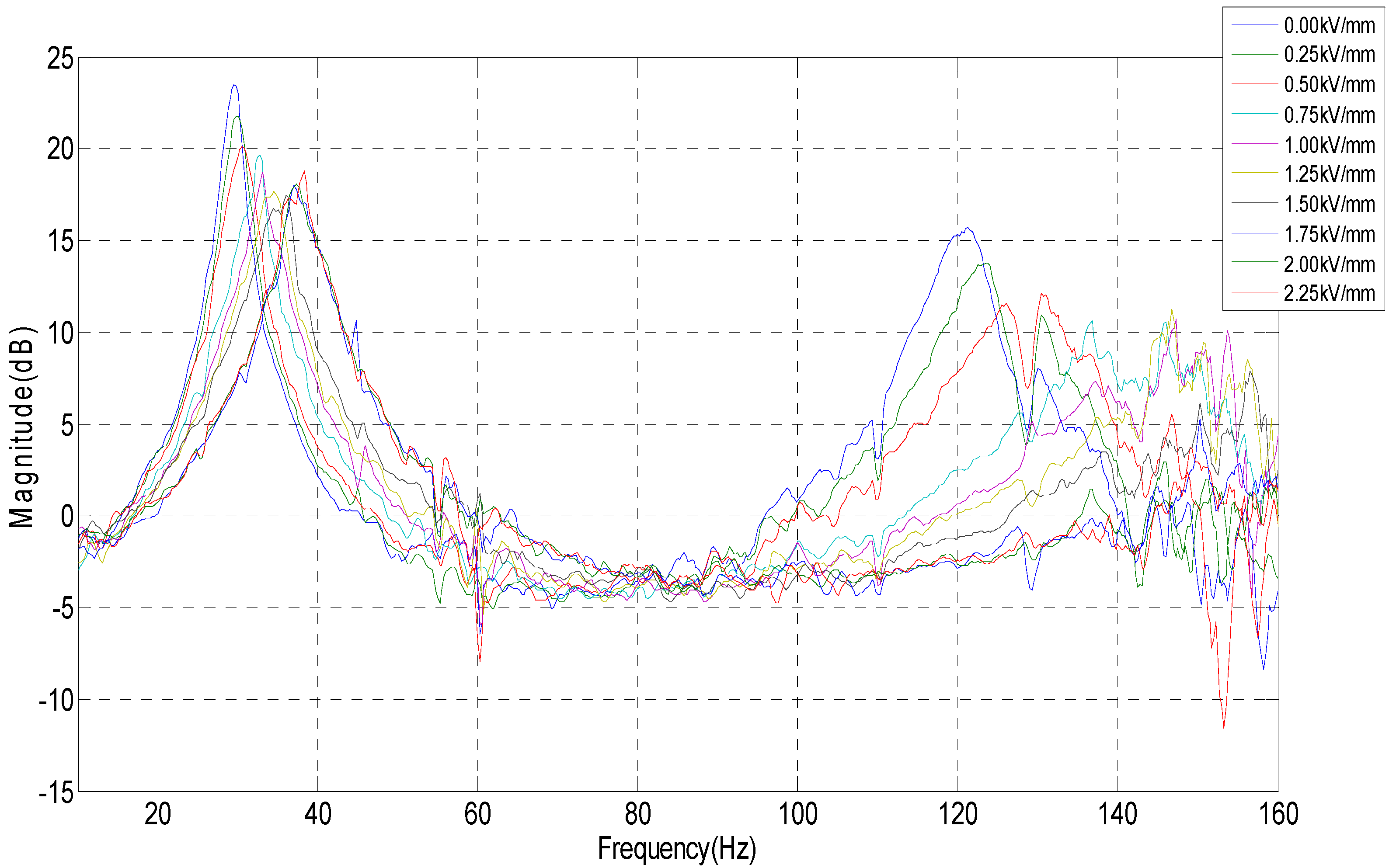
Figure 4.
Frequencies used in the half-power point bandwidth method.

Figure 5.
Schematic diagram of the sandwich plate with ER material embedded between two plates.
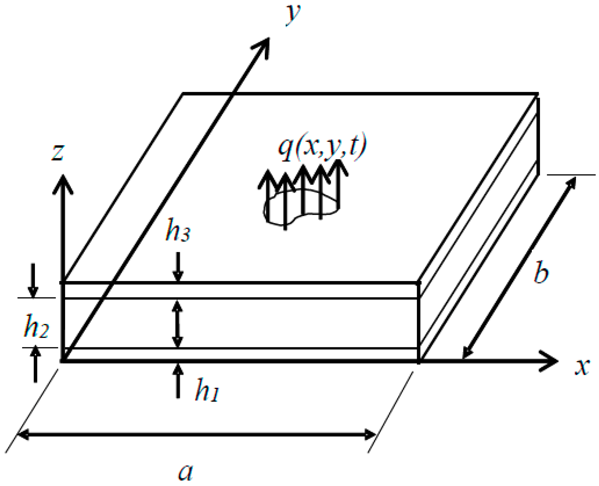
Figure 6.
Thin plate with the ERF embedded ATVAs.

Figure 7.
The first three simulated vibration mode shapes of this plate structure with the ERF embedded ATVA. (a) First mode; (b) Second mode; (c) Third mode.
Figure 7.
The first three simulated vibration mode shapes of this plate structure with the ERF embedded ATVA. (a) First mode; (b) Second mode; (c) Third mode.

Figure 8.
Simulated frequency responses of the plate structure with the ERF embedded ATVA (w = 36) as different electric fields are applied.
Figure 8.
Simulated frequency responses of the plate structure with the ERF embedded ATVA (w = 36) as different electric fields are applied.

Figure 9.
Experimental setup to measure the dynamic properties of the plate structure with the ERF embedded ATVA. (a) schematic diagram; (b) measurement point in the front view.
Figure 9.
Experimental setup to measure the dynamic properties of the plate structure with the ERF embedded ATVA. (a) schematic diagram; (b) measurement point in the front view.
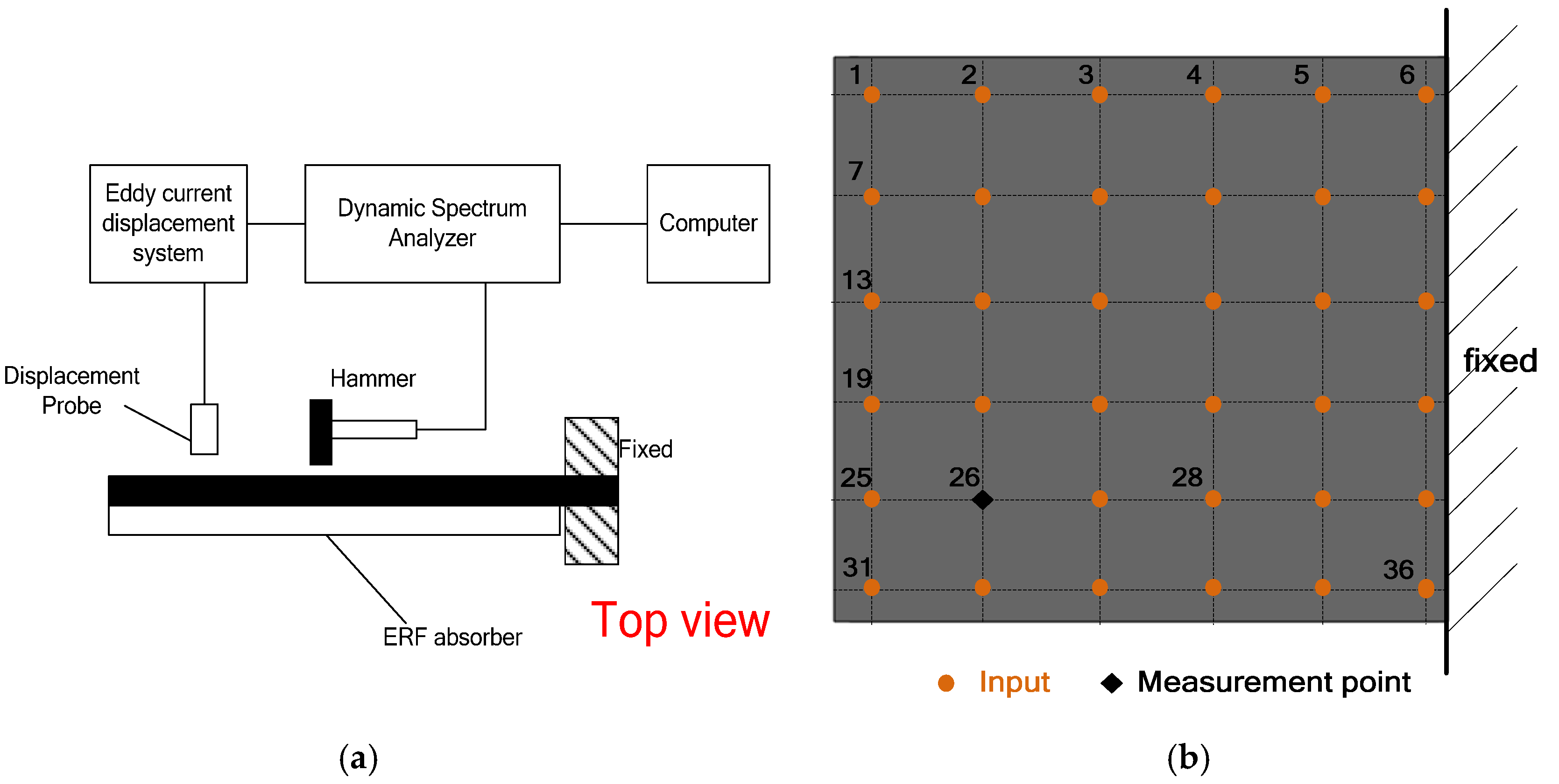
Figure 10.
Experimental mode shapes of this plate structure with the ERF embedded ATVA at the first three vibration modes. (a) the first mode; (b) the second mode; (c) the third mode.
Figure 10.
Experimental mode shapes of this plate structure with the ERF embedded ATVA at the first three vibration modes. (a) the first mode; (b) the second mode; (c) the third mode.
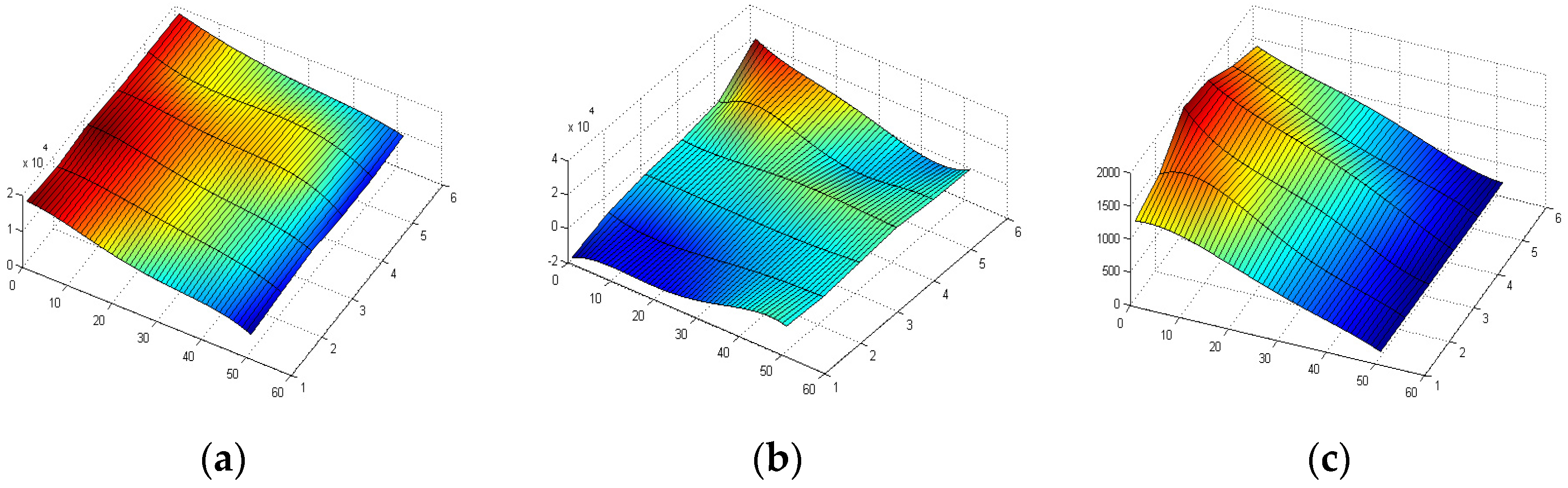
Figure 11.
Experimental setup to measure the dynamic properties of the smart structure with different external electrical filed. (a) side view; (b) front view.
Figure 11.
Experimental setup to measure the dynamic properties of the smart structure with different external electrical filed. (a) side view; (b) front view.
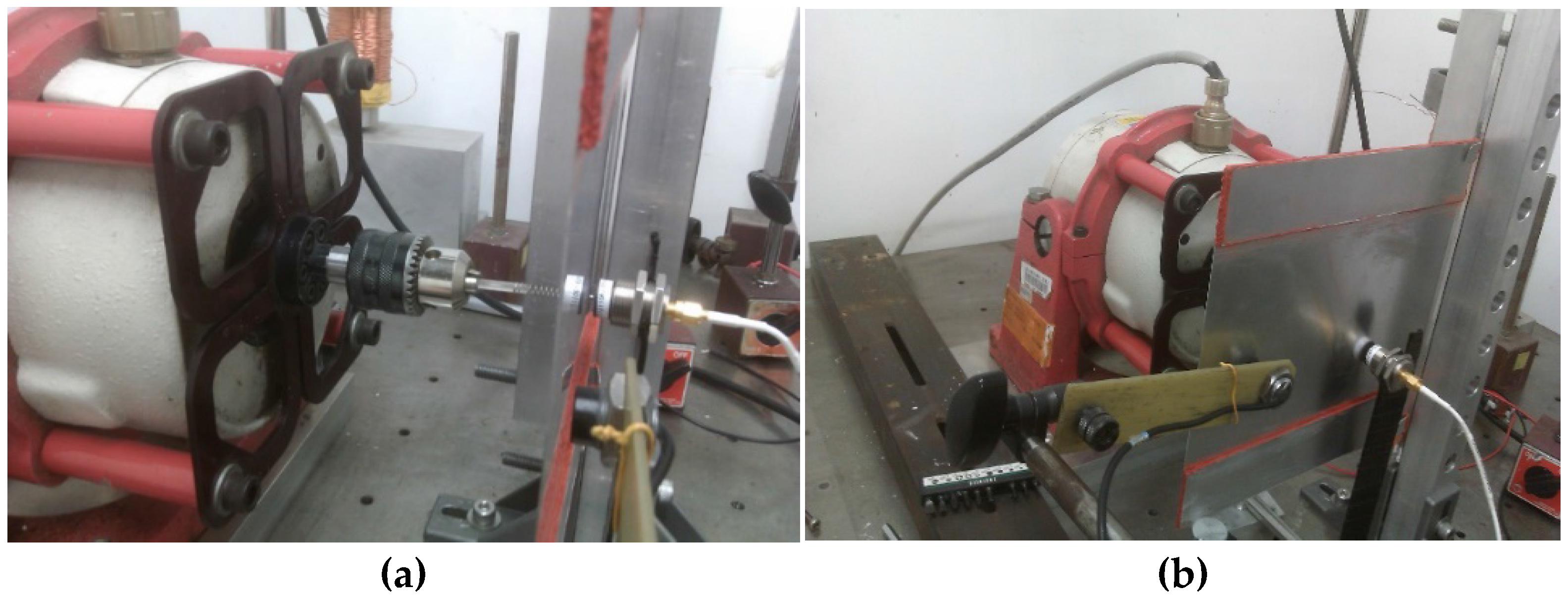
Figure 12.
Experimental schematic diagram of semi-active vibration control architecture for the ERF embedded ATVA.
Figure 12.
Experimental schematic diagram of semi-active vibration control architecture for the ERF embedded ATVA.

Figure 13.
Type-2 fuzzy membership function for the two inputs: (a) the root-mean-square (rms) value of displacement; (b) vibration frequency.
Figure 13.
Type-2 fuzzy membership function for the two inputs: (a) the root-mean-square (rms) value of displacement; (b) vibration frequency.
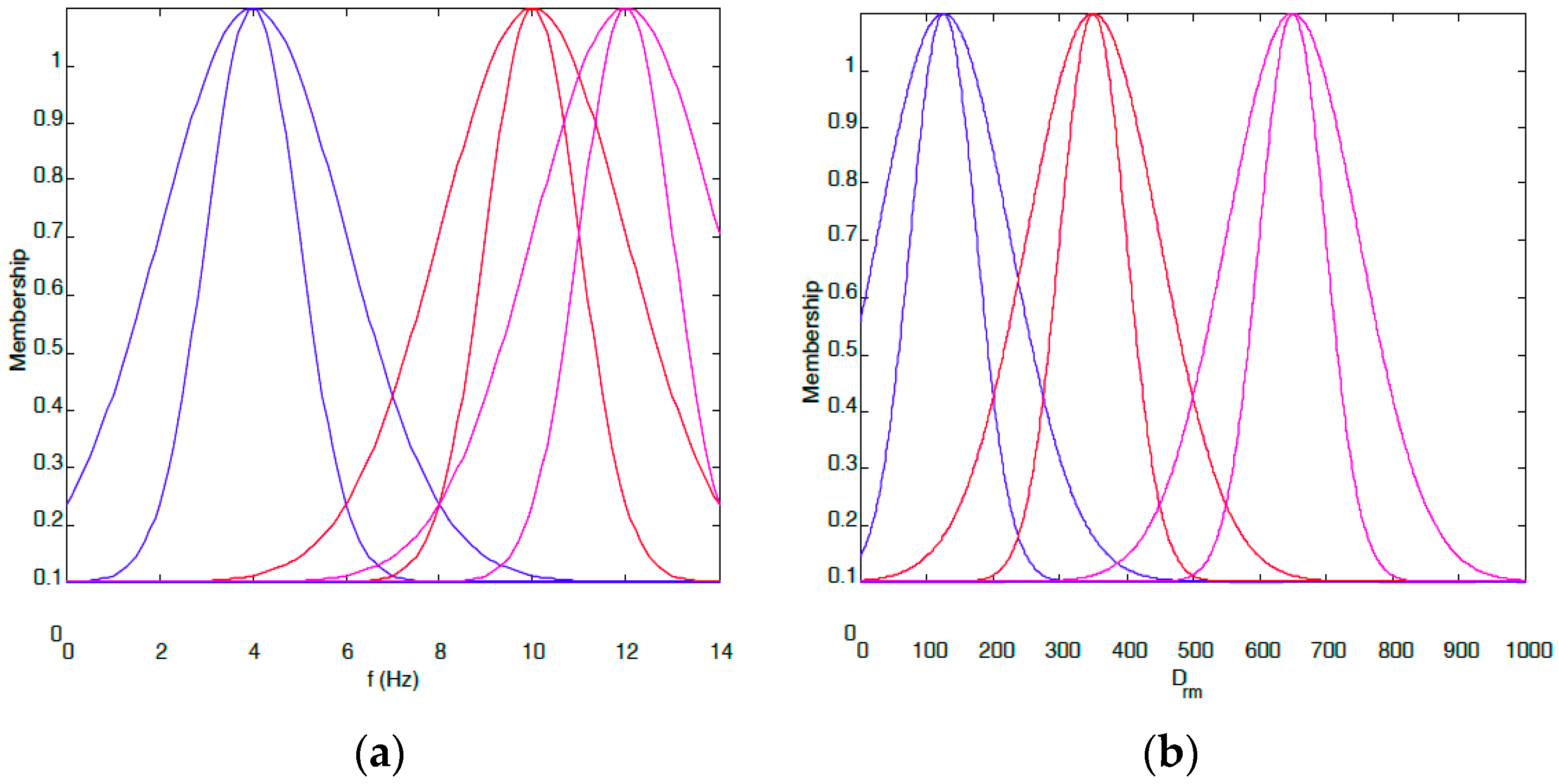
Figure 14.
Main inference structure of type-2 fuzzy system.

Figure 15.
Inference operation to obtain the output.
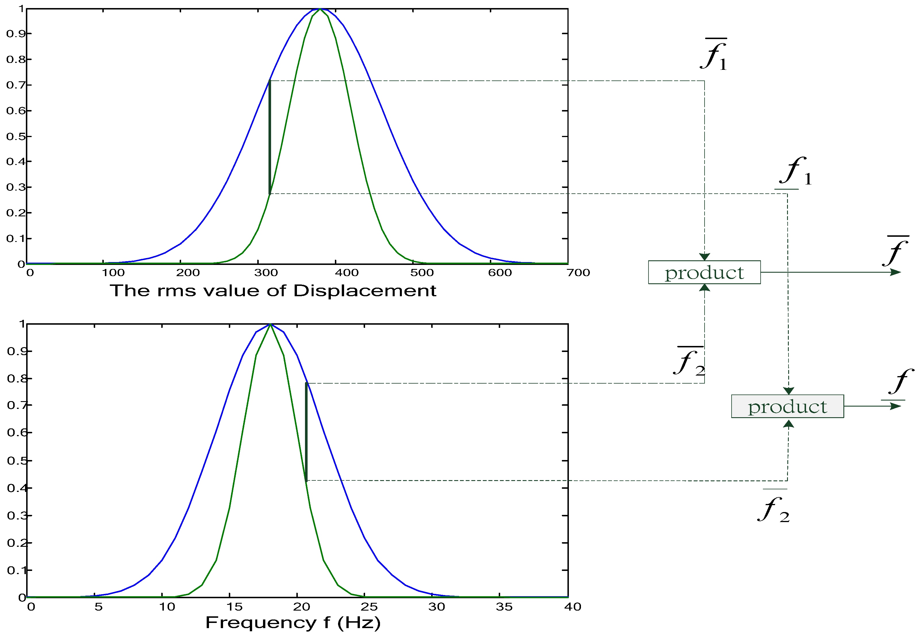
Figure 16.
Main inference structure of the proposed type-2 fuzzy controller of the first mode.
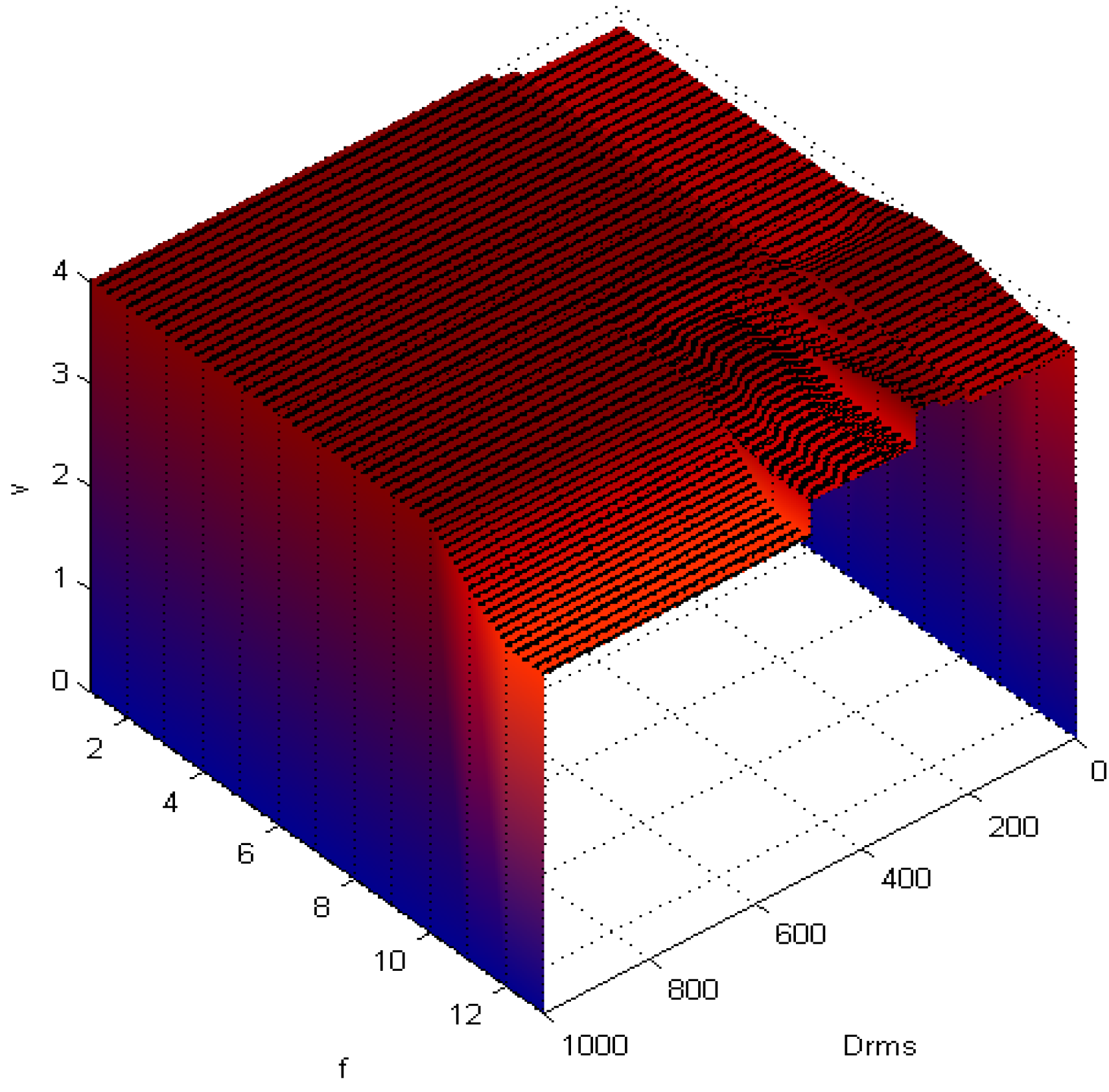
Figure 17.
Main inference structure of the proposed type-2 fuzzy controller of the second and third mode. (a) the second mode’s inference structure; (b) the third mode’s inference structure.
Figure 17.
Main inference structure of the proposed type-2 fuzzy controller of the second and third mode. (a) the second mode’s inference structure; (b) the third mode’s inference structure.

Figure 18.
Proposed switching algorithm of the fuzzy controller according to the frequency response.
Figure 18.
Proposed switching algorithm of the fuzzy controller according to the frequency response.
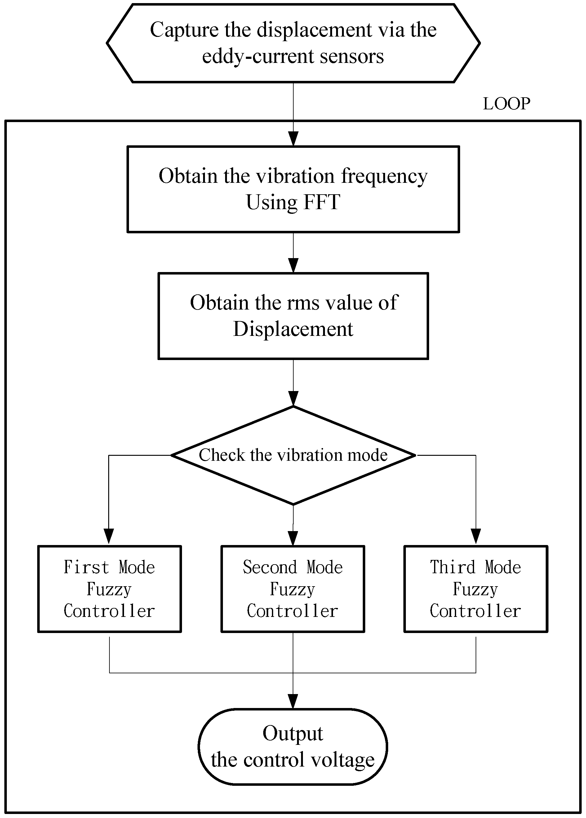
Figure 19.
Real-time embedded code for the NI CRIO 9074.
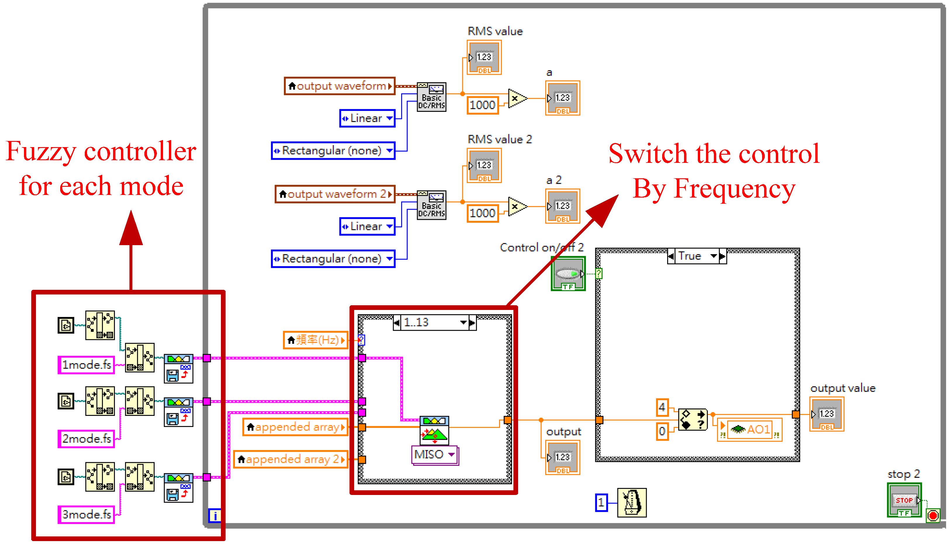
Figure 20.
Experimental results of the smart structure for the external vibration at 8 and 10 Hz with the stimulating signal of 200 mVpk. (a) the response at 8 Hz; (b) the response at 10 Hz.
Figure 20.
Experimental results of the smart structure for the external vibration at 8 and 10 Hz with the stimulating signal of 200 mVpk. (a) the response at 8 Hz; (b) the response at 10 Hz.

Figure 21.
Experimental results of the smart structure for the external vibration at 18 and 20 Hz with the stimulating signal of 200 mVpk. (a) the response at 18 Hz; (b) the response at 20 Hz.
Figure 21.
Experimental results of the smart structure for the external vibration at 18 and 20 Hz with the stimulating signal of 200 mVpk. (a) the response at 18 Hz; (b) the response at 20 Hz.

Figure 22.
Experimental results of the smart structure for the external vibration at 75 and 77 Hz with the stimulating signal of 200 mVpk. (a) the response at 75 Hz; (b) the response at 77 Hz.
Figure 22.
Experimental results of the smart structure for the external vibration at 75 and 77 Hz with the stimulating signal of 200 mVpk. (a) the response at 75 Hz; (b) the response at 77 Hz.

Figure 23.
Time response of the structure’s displacement for the real-time experiment for the external vibration with the varying frequencies.
Figure 23.
Time response of the structure’s displacement for the real-time experiment for the external vibration with the varying frequencies.


Table 1.
Specifications of the ERF (electrorheological fluid) sandwich beam.
| L | W | h1 | w1 | h2 |
|---|---|---|---|---|
| 150 mm | 30 mm | 0.3 mm | 2.5 mm | 2 mm |
| Adhesives | ERF% | Volume | Weight | Equivalent density |
| Silicone Sealant | 45% | 7.25 mL | 28.6 g | 2118.52 kg/m3 |
Table 2.
Damping ratio of the ERF-ATVA (actively tunable vibration absorbers) for different electric fields.
Table 2.
Damping ratio of the ERF-ATVA (actively tunable vibration absorbers) for different electric fields.
| E (kV/mm) | F (Hz) | Amplitude (dB) | Damping Ratio (ζ) |
|---|---|---|---|
| 0 | 29.5 | 23.473 | 0.0363 |
| 0.25 | 29.75 | 21.777 | 0.0432 |
| 0.5 | 30.5 | 20.127 | 0.0573 |
| 0.75 | 32.75 | 19.658 | 0.0574 |
| 1 | 33 | 18.705 | 0.0587 |
| 1.25 | 34.5 | 17.700 | 0.0589 |
| 1.5 | 36 | 17.457 | 0.0593 |
| 1.75 | 37 | 17.961 | 0.0529 |
| 2 | 37.25 | 18.075 | 0.0560 |
| 2.25 | 38.25 | 18.774 | 0.0512 |
Table 3.
Frequency shifts at the vibration models of this structure equipped with the ERF embedded ATVA (with the width from 20 to 36 mm) for the electric field changed from 0 to 2 kV/mm.
Table 3.
Frequency shifts at the vibration models of this structure equipped with the ERF embedded ATVA (with the width from 20 to 36 mm) for the electric field changed from 0 to 2 kV/mm.
| W (mm) | 1st Mode Variation (Hz) | 2nd Mode Variation (Hz) | 3rd Mode Variation (Hz) |
|---|---|---|---|
| 20 | 1.362 | 1.811 | 10.069 |
| 22 | 1.331 | 1.724 | 10.756 |
| 24 | 1.406 | 1.939 | 14.912 |
| 26 | 1.378 | 1.862 | 16.391 |
| 28 | 1.392 | 1.825 | 17.613 |
| 30 | 1.374 | 1.86 | 18.352 |
| 32 | 1.357 | 1.963 | 18.790 |
| 34 | 1.399 | 1.941 | 18.980 |
| 36 | 1.361 | 2.001 | 19.157 |
Table 4.
Frequency and amplitude of the first mode vibration response for this structure equipped with the ERF embedded ATVA according to the electric field (0–2 kV/mm).
Table 4.
Frequency and amplitude of the first mode vibration response for this structure equipped with the ERF embedded ATVA according to the electric field (0–2 kV/mm).
| E (kV/mm) | F (Hz) | Amplitude (dB) | Damping Ratio (ζ) |
|---|---|---|---|
| 0 | 11.625 | 16.103 | 0.0218 |
| 0.5 | 11.875 | 10.142 | 0.0140 |
| 1 | 12 | 12.677 | 0.0205 |
| 1.5 | 12.375 | 15.809 | 0.0541 |
| 2 | 13.375 | 11.629 | 0.0329 |
Table 5.
Frequency and amplitude of the second mode vibration response for this structure equipped with the ERF embedded ATVA according to the electric field (0–2 kV/mm).
Table 5.
Frequency and amplitude of the second mode vibration response for this structure equipped with the ERF embedded ATVA according to the electric field (0–2 kV/mm).
| E (kV/mm) | F (Hz) | Amplitude (dB) | Damping Ratio (ζ) |
|---|---|---|---|
| 0 | 18.375 | 17.876 | 0.0156 |
| 0.5 | 18.125 | 14.201 | 0.0129 |
| 1 | 18.25 | 12.423 | 0.0212 |
| 1.5 | 18.5 | 14.365 | 0.0151 |
| 2 | 18.5 | 15.304 | 0.0119 |
Table 6.
Frequency and amplitude of the third mode vibration response for this structure equipped with the ERF embedded ATVA according to the electric field (0–2 kV/mm).
Table 6.
Frequency and amplitude of the third mode vibration response for this structure equipped with the ERF embedded ATVA according to the electric field (0–2 kV/mm).
| E (kV/mm) | F (Hz) | Amplitude (dB) | Damping Ratio (ζ) |
|---|---|---|---|
| 0 | 77 | 20.795 | 0.0083 |
| 0.5 | 77.625 | 19.547 | 0.0087 |
| 1 | 77.875 | 17.414 | 0.0108 |
| 1.5 | 78.125 | 18.382 | 0.0122 |
| 2 | 78.625 | 17.588 | 0.0119 |
Table 7.
Frequency responses of this smart structure with respect to the different external electric field applied to ERF for the external vibration at 8–25 Hz.
Table 7.
Frequency responses of this smart structure with respect to the different external electric field applied to ERF for the external vibration at 8–25 Hz.
| Shaker Amplitude (mVpk) | 50 | 100 | 200 | 50 | 100 | 200 | |
|---|---|---|---|---|---|---|---|
| 8 Hz Displacement (mVrms) | 10 Hz Displacement (mVrms) | ||||||
| E (kV/mm) | 1 | 98 | 201 | 413 | 162 | 312 | 633 |
| 1.5 | 82 | 181 | 363 | 148 | 267 | 515 | |
| 2 | 86 | 162 | 338 | 129 | 218 | 403 | |
| 13 Hz Displacement (mVrms) | 17 Hz Displacement (mVrms) | ||||||
| E (kV/mm) | 1 | 17 | 35 | 68 | 98 | 194 | 378 |
| 1.5 | 14 | 28 | 53 | 85 | 181 | 363 | |
| 2 | 8 | 13 | 27 | 72 | 155 | 352 | |
| 19 Hz Displacement (mVrms) | 21 Hz Displacement (mVrms) | ||||||
| E (kV/mm) | 0 | 33 | 75 | 153 | 28 | 54 | 110 |
| 0.5 | 36 | 77 | 158 | 25 | 52 | 106 | |
| 1 | 37 | 78 | 159 | 26 | 53 | 108 | |
| 23 Hz Displacement (mVrms) | 25 Hz Displacement (mVrms) | ||||||
| E (kV/mm) | 0 | 21 | 41 | 80 | 16 | 34 | 69 |
| 0.5 | 22 | 41 | 82 | 17 | 34 | 70 | |
| 1 | 22 | 41 | 81 | 16 | 34 | 71 | |
Table 8.
Frequency responses of this smart structure with respect to the different external electric field applied to ERF for the external vibration at 74–80 Hz.
Table 8.
Frequency responses of this smart structure with respect to the different external electric field applied to ERF for the external vibration at 74–80 Hz.
| Shaker Amplitude (mVpk) | 50 | 100 | 200 | 50 | 100 | 200 | |
|---|---|---|---|---|---|---|---|
| 74 Hz Displacement (mVrms) | 76 Hz Displacement (mVrms) | ||||||
| E (kV/mm) | 1 | 4 | 7 | 13 | 9 | 20 | 39 |
| 1.5 | 3 | 6 | 12 | 8 | 19 | 37 | |
| 2 | 5 | 8 | 14 | 10 | 20 | 37 | |
| 78 Hz Displacement (mVrms) | 80 Hz Displacement (mVrms) | ||||||
| E (kV/mm) | 0 | 26 | 53 | 104 | 15 | 30 | 61 |
| 0.5 | 18 | 33 | 68 | 15 | 30 | 60 | |
| 1 | 16 | 29 | 58 | 20 | 41 | 78 | |
| 1.5 | 14 | 23 | 47 | 23 | 46 | 87 | |
Table 9.
Right and left fuzzy rule tables for the first mode.
| Drms | VS | S | M | |
|---|---|---|---|---|
| f | ||||
| VS | B | VB | VB | |
| S | VB | V | VB | |
| M | M | VB | M | |
Table 10.
Experimental results at the frequencies of 8, 10, 18, 20, 75 and 77 Hz using the type-1 and type-2 fuzzy controller.
Table 10.
Experimental results at the frequencies of 8, 10, 18, 20, 75 and 77 Hz using the type-1 and type-2 fuzzy controller.
| Excitation Frequency (Hz) | Type-1 Fuzzy Controller (%) | Type-2 Fuzzy Controller (%) |
|---|---|---|
| 8 | 81.4 | 81.5 |
| 10 | 19.9 | 36.1 |
| 18 | 38.3 | 40.9 |
| 20 | 24.8 | 40.3 |
| 77 | 88.6 | 89.7 |
| 79 | 37.3 | 54.2 |
© 2017 by the authors. Licensee MDPI, Basel, Switzerland. This article is an open access article distributed under the terms and conditions of the Creative Commons Attribution (CC BY) license (http://creativecommons.org/licenses/by/4.0/).
Share and Cite
MDPI and ACS Style
Lin, C.-J.; Lee, C.-Y.; Liu, Y. Vibration Control Design for a Plate Structure with Electrorheological ATVA Using Interval Type-2 Fuzzy System. Appl. Sci. 2017, 7, 707. https://doi.org/10.3390/app7070707
AMA Style
Lin C-J, Lee C-Y, Liu Y. Vibration Control Design for a Plate Structure with Electrorheological ATVA Using Interval Type-2 Fuzzy System. Applied Sciences. 2017; 7(7):707. https://doi.org/10.3390/app7070707
Chicago/Turabian StyleLin, Chih-Jer, Chun-Ying Lee, and Ying Liu. 2017. "Vibration Control Design for a Plate Structure with Electrorheological ATVA Using Interval Type-2 Fuzzy System" Applied Sciences 7, no. 7: 707. https://doi.org/10.3390/app7070707
Note that from the first issue of 2016, this journal uses article numbers instead of page numbers. See further details here.