1. Introduction
Atmospheric pressure plasmas based devices are suitable solutions to generate transient or stationary plasmas, with various applications. Plasma jets are a distinct category of plasma sources, with specific transport of active species, able to be integrated in production lines or to be used in single, specific applications. Over the past half-century, atmospheric pressure plasma jets (APPJ) were widely used for technological applications, starting with thermal plasma jets used for propulsion, cutting and welding devices or materials deposition [
1]. Subsequently, non-thermal plasma jets were developed in various configurations, as response to the increasing industry demands to process heat sensitive materials. Recently, this opened the possibility to accurately study the plasma jets facing natural biological architectures or living organisms. These are unique natural molecular structures, presenting a hierarchical organization with many levels, able to respond to external stimuli, to self-repair and to replace damaged molecules or sub-assemblies, often showing an increasing resistance to various forms of stress factors. Plasma medicine and plasma agriculture represents nowadays distinct research topics in many plasma laboratories. The advancement of the plasma community in this field and bridging with new communities, such as biologists and medical doctors, led to numerous applications of plasma physics in life sciences during the last decade. They involve sterilization and decontamination of liquids, medical surfaces, implants or skin; influences over cellular processes: wound healing, dermatological diseases, cancer cells targeting; dentistry and related applications and treatment of seeds or vegetal tissues [
2]. Cancer treatment is certainly one major topic of research, due to the fact that preliminary results of different groups indicate that selectivity may be achieved under specific plasma treatment conditions [
3,
4].
In order to distinguish between the different studied plasma jets, a series of parameters may be used to classify these plasma sources: thermal equilibrium, geometry and gas environment, electrical field configuration, excitation method, stationary versus transient processes [
1]. It is thus possible to identify local thermodynamic equilibrium (LTE) plasma jets (based on arc and torches) and non-LTE plasma jets (based on barrier, corona, radiofrequency or microwave discharges). The working gas is usually helium or argon, but we may also find studies on nitrogen or air plasma jets. The geometrical parameters of these plasma jets and the materials used to assembly the device are very numerous [
5]. Thus sometimes the biological effects of plasma jets are strongly conflicting, being even opposite in certain studies [
6,
7,
8,
9,
10].
The barrier discharge is a frequently used experimental solution to generate the APPJ in various gas mixtures, at atmospheric pressure. A dielectric cylinder (made usually of quartz, alumina or plastic), having internal diameter in mm or sub-mm range, is used as flow channel for the working gas, injected continuously at flow rates that maintains laminar flow inside the tube and outside for a limited distance. External conductive tape electrodes or other electrode configurations, including internal tip or needle electrodes are used to generate transient electric fields, with imposed geometry, in order to induce gas breakdown. For appropriate numbers of electronic avalanches, followed by individual streamer development, a volume discharge is generated by streamers coupling, having the aspect of a millimeter sized plasma column. The discharge is sustained for a limited period of time, from nanosecond to microseconds depending mainly on the rise time of the applied voltage pulse and the characteristics of the dielectric materials. The intensity of electric current in the plasma column and arc transition are limited by the dielectric material. Gas heating is avoided and the plasma gas temperature is maintained around room temperature, this being one of the main advantages of using the APPJ in direct contact with living tissues, biomolecular architectures or other thermolabile materials. It is interesting to note that miniaturisation of some plasma jets is possible using capillary dielectric tubes [
11,
12]. For example plasma jets with diameter values in submillimeter range can be generated and used to induce controllable effects on proteins and amino acids, for local etching of biomolecular films, local chemical functionalization, patterning, and local modification of physical parameters such as roughness or optical properties [
13]. Due to very low dimensions of this plasma jet we foresee that single cell exposure to plasma action is also a topic to be studied in the following period, since single cell-experiments represent cutting edge studies in modern cell biology.
Concerning direct applications of plasma jets on living animal tissues, it is interesting to analyse the physical and chemical agents delivered at the interphase. When trying to identify the factors able to induce modification of biological molecules or generate a biological response, one will find a list of agents already used independently in various medical practices. We will emphasise here: increase of local temperature (used in thermotherapy methods), pulsed charge transport (i.e., ac or pulsed electrical current, used in many electrotherapy methods), charge accumulation and related electric fields (used in electroporation techniques), photon flashes in various spectral ranges (i.e., ultraviolet (UV), visible (VIS), near infrared (NIR), used in phototherapy methods), chemical agents in form of oxygen and nitrogen reactive species (e.g., O, OH, O2(1g), O3, H2O2, NO, NO2, delivered by various forms of drugs). Very often, synergy occurs and plasma treatment is more efficient than the individual use of physical or chemical agents.
Characterization of plasma jets is usually achieved by means of electrical, optical and spectroscopic diagnostic techniques. For example, applied voltage and discharge monitoring are indispensable for quick check of plasma operation regime, while emission spectroscopy is widely used to get information on excited atomic and molecular species in plasma jet volume, or to estimate plasma characteristic temperatures [
14,
15]. Rotational spectra analysis for molecular ions and neutrals, using Boltzmann plot method or numerical simulation, in order to calculate the real gas temperature has only limited applicability for transient dielectric barrier discharge plasmas, giving the maximum temperature occurring during discharge. This methods overestimates the gas actual temperature values, as obtained using others physical principles to return the gas temperature value. For example using alternative methods based on fiber optic temperature sensors, immune to electromagnetic interferences, returns an gas temperature increase of only few tens of degrees Celsius for helium dielectric barrier discharges [
16,
17]. During the last years, mass spectrometry studies of atmospheric pressure plasma jets became an appropriate technique to identify atomic and molecular species present in the plasma volume, either neutral or charged states. Time resolved studies or ion energy distribution are supplementary data that can be obtained from mass spectrometry investigations. Sampling of plasma species is usually done by differential pumping, ensuring a collision free molecular beam, in order to measure with high accuracy the same species as the ones present in plasma volume. A high variety of nitrogen and oxygen neutral molecules and molecular ions are observed in the discharge volume [
18,
19,
20].
This paper aims to present fundamental aspects related to the physics of atmospheric pressure helium plasma jet, generated using the barrier discharge principle. Experimental results related to the influence of electrical operational parameters on discharge current scaling, warm-up period of the discharge, ionization wave propagation or mass spectrometry data for the same helium plasma jet are presented. These data sets could prove to be valuable for plasma engineers dealing with technology transfer for medical devices market.
2. Experimental Set-Up and Methods
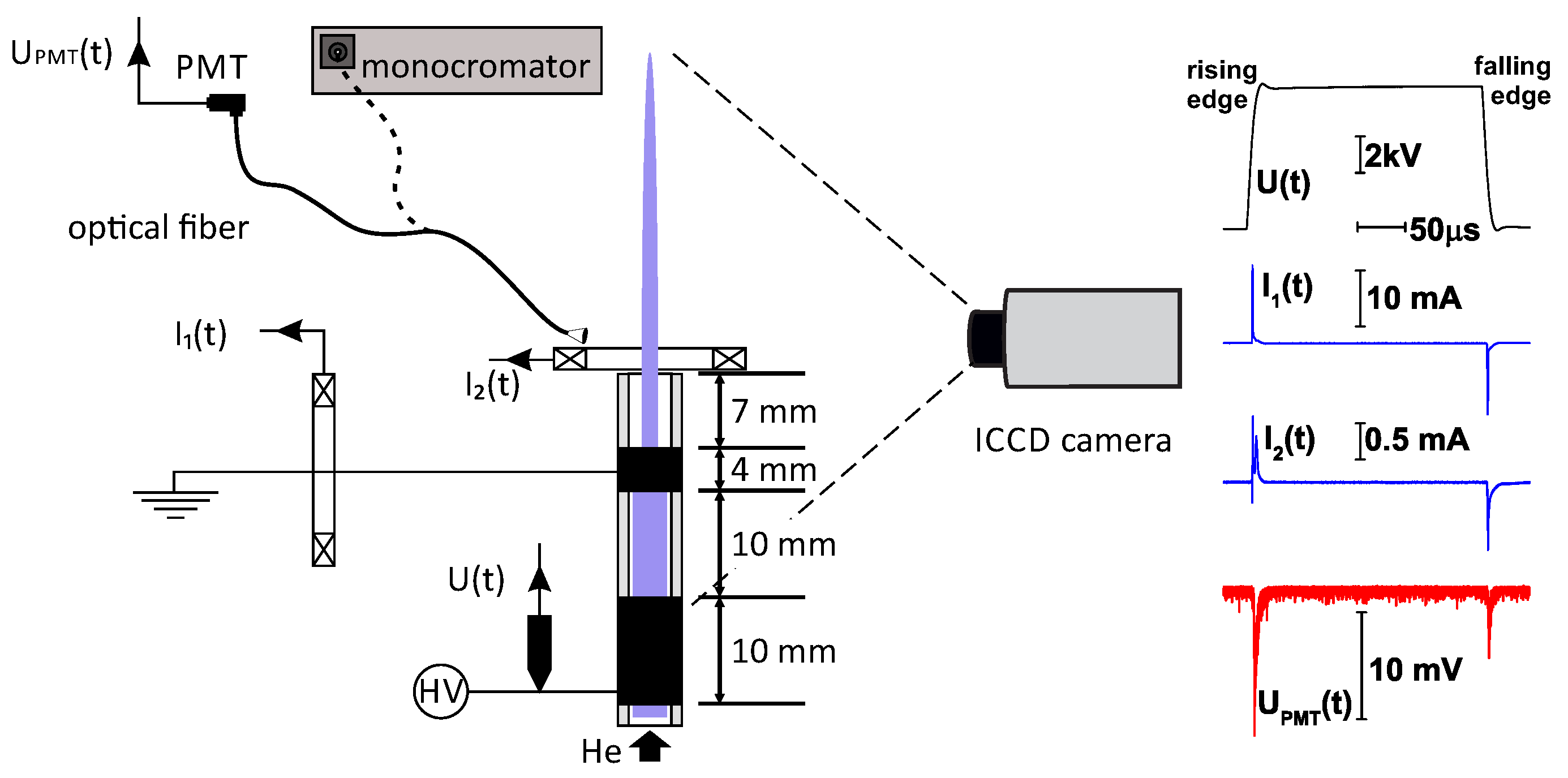
Figure 1 presents a schematic of a common technological solution to generate the helium APPJ. Aluminium foil adhesive tape electrodes are applied to a quartz tube (4 mm inner diameter, 6 mm outer diameter), hosting a 4.6 helium channel at 3 L/min flow rate, maintained constant by a digital flow meter (MKS 1179A, MKS Instruments, Inc., Andover, MA, USA). The separation distances, starting from the nozzle are: 7 mm gap, 4 mm width grounded electrode, 10 mm discharge gap, 10 mm width powered electrode. A vertical arrangement, with the plasma jet oriented upwards, was used in this study to minimize buoyancy effects. The relative humidity of ambient air was continuously monitored and no significant changes were observed during all experiments (60 ± 1% RH).
Rectangular high voltage (HV) pulses are delivered to the powered electrode, using a voltage amplifier (TREK, Inc., Lockport, NY, USA, Model PD07016) and a digital waveform generator (Tektronix, Inc., Beaverton, OR, USA, model AFG3022B). The operational parameters of the plasma jet used in this study are detailed in
Table 1. The rise/fall time (10% to 90%) of the high voltage pulse was ranging from 6.5 to 9.2
s function of all studied parameters of the HV pulses: frequency, width and amplitude.
Plasma operation monitoring was ensured by external electrical measurements of applied voltage and electrical currents using probes: Tektronix P6015A (Tektronix, Inc., Beaverton, OR, USA) and two Pearson 6585 (Pearson Electronics, Palo Alto, CA, USA) (to simultaneously measure the current on the ground line, and the plasma jet current, ) connected to digital scope (Tektronix, Inc., Beaverton, OR, USA, model TDS5034, 350 MHz bandwidth, 5 GSample/s sampling rate). The signal measured by the high voltage probe was used to trigger the oscilloscope, at a level of maximum 2.5% from the maximum voltage amplitude. Thus, with a very good approximation, the origin of time (t = 0) is considered to be the HV pulse rise start point for positive polarity HV pulses or the pulse fall start point for negative polarity HV pulses.
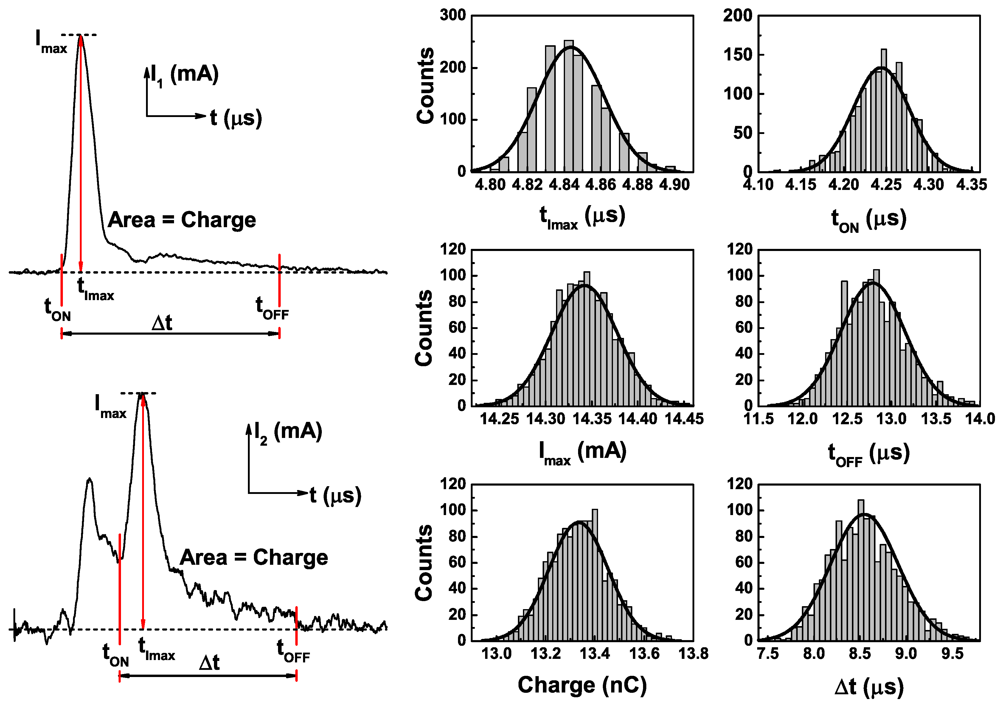
In order to test the transient response of the plasma jet, due to gas flow stabilization and mixture with air, outside the dielectric tube, the following experimental approach was used: immediately after switching on the helium flow and the HV amplifier output, acquisition of all electrical parameters was performed at a 15 s time step. Using the FastFrame(TM) Segmented Memory acquisition mode of the scope it was possible to capture bursts of 1419 frames, i.e., consecutive individual discharge events. In this way during all experiments we stored more than 3105 individual current traces. All data were subsequently analysed using a custom code, in order to obtain from the
and
traces simultaneously recorded by the two current probes, the following parameters for each discharge event: ignition (
) and extinction (
) time, current pulse duration (
=
−
), peak value of the current (
), the time value corresponding to peak current (
) and the integral of the current signal from
to
(i.e., total transported charge during a single discharge event). The ignition time
for current
and extinction time
for
and
currents are defined where the current amplitude reach 3% of
current. As can be observed in the typical current traces in
Figure 2, the second current probe, used to monitor the plasma jet current (
) measures also a small signal related to the ground line current due to the small separation distance between the ground electrode and the dielectric tube nozzle. Taking this into account ignition time
for
current is defined where the current has a minimum between the Imax current and the maximum signal related to the ground line current. Independent measurements were performed for currents observed during the rising and the falling edges of the HV pulses. Frequency count was computed for all returned data and we found that all parameters follow a normal distribution (
Figure 2). The mean value and standard deviation (SD) of all parameters were used to describe the statistical behaviour of the discharge events, as function of elapsed time from turning on the plasma jet or selected operational parameters.
The above described experimental methodology was also employed to study the influence of selected plasma source operational parameters on discharge current statistical behaviour. All experiments were carried out 20 to 30 min after switching on the helium flow and the HV amplifier output (quasi steady state regime). Extensive measurements of all operational parameters were performed by averaging the voltage and current waveforms on 512 frames using the digital scope and storing the results for further analyses.
For all above described electrical measurements, displacement currents were recorded for all studied experimental conditions, in the absence of helium flow, and were subsequently subtracted from the total current to obtain the discharge current (i.e., gap current).
Beside electrical measurements, optical emission spectroscopy was used to study emission spectra of the plasma jet using a monochromator equipped with 600 grooves/mm and 2400 grooves/mm scanning gratings (Horiba Ltd., Kyoto, Japan, model Triax 550 with Symphony CCD detector). By placing the optical fiber on the axial position of the plasma jet, the integral intensity of selected spectral bands and lines was monitored during plasma jet operation with a 1 s time step, using fixed grating spectrometer (AVS-USB2000 from Avantes BV, Apeldoorn, The Netherlands). Furthermore, the integral light emitted by the plasma jet can be monitored using a photomultiplier (PMT, Hamamatsu Photonics K.K., Hamamatsu, Japan, model R955) or a gated ICCD camera (Hamamatsu Photonics K.K., Hamamatsu, Japan, model C8484-05G), using a Canon (Canon Inc., Tokyo, Japan) EF-S 18–55 mm f/3.5–5.6 lens. Using 30 ns gate width and 100 ns time step, dynamics of the ionization wave outside the dielectric tube was studied. To avoid hydrodynamic instabilities, due to the convection currents in the room, the jet was surrounded by a supplementary 30 mm diameter quartz tube.
The HPR-60 Molecular Beam Sampling Mass Spectrometer System (Hiden Analytical Ltd., Warrington, UK, with 2500 amu upper mass range) was used to study the atmospheric plasma jet chemistry’s composition. This quadrupole-based mass filter system consists of three differential pumping stages, separated by three aligned skimmer cones and is able to extract neutrals or ions from atmospheric pressure, ensuring a collision free molecular beam to its detector. To extract positive or negative charged species from plasma volume, the aligned cones were properly biased, tuned for a maximum signal and carefully adjusted so as to not induce additional ionizations processes. The first cone is not grounded (as factory default) and the diameter of the extraction orifice was 100
m, similar to most previous mass spectrometry studies of APPJ [
21,
22,
23,
24,
25,
26] or basic inductively coupled plasma-mass spectrometry set-ups. It worth to note that in some other studies the extraction orifice was smaller [
27] or not mentioned [
20,
28]. All mass spectrometry data are time averaged using 20 ms as integration time for each mass number. The final results are then obtained as an average of ten independent spectra.
3. Results and Discussion
A typical characteristic of barrier discharges is the generation of charge transport during the rising and falling edges of the HV pulses, due to external electric field and respectively internal electric field gas breakdown. The measured current traces (shown on right side of
Figure 1) have the following characteristics: single current peaks on both edges of the HV pulses, with rapid increase up to a maximum value and a slow decrease to zero. It is valuable to mention that the second current probe measures a positive current peak only during the rising edge of the HV pulses, corresponding to the guided streamer propagation outside the dielectric tube. The negative current peak, characteristic to dielectric barrier discharges, is associated with a discharge event generated only in the spatial region delimited by dielectrics, that can accumulate charge during first phase on discharge (i.e., rising edge of HV pulses) and produce an internal field inversion during falling edge of HV pulses.
3.1. Plasma Jet Warm-Up Period
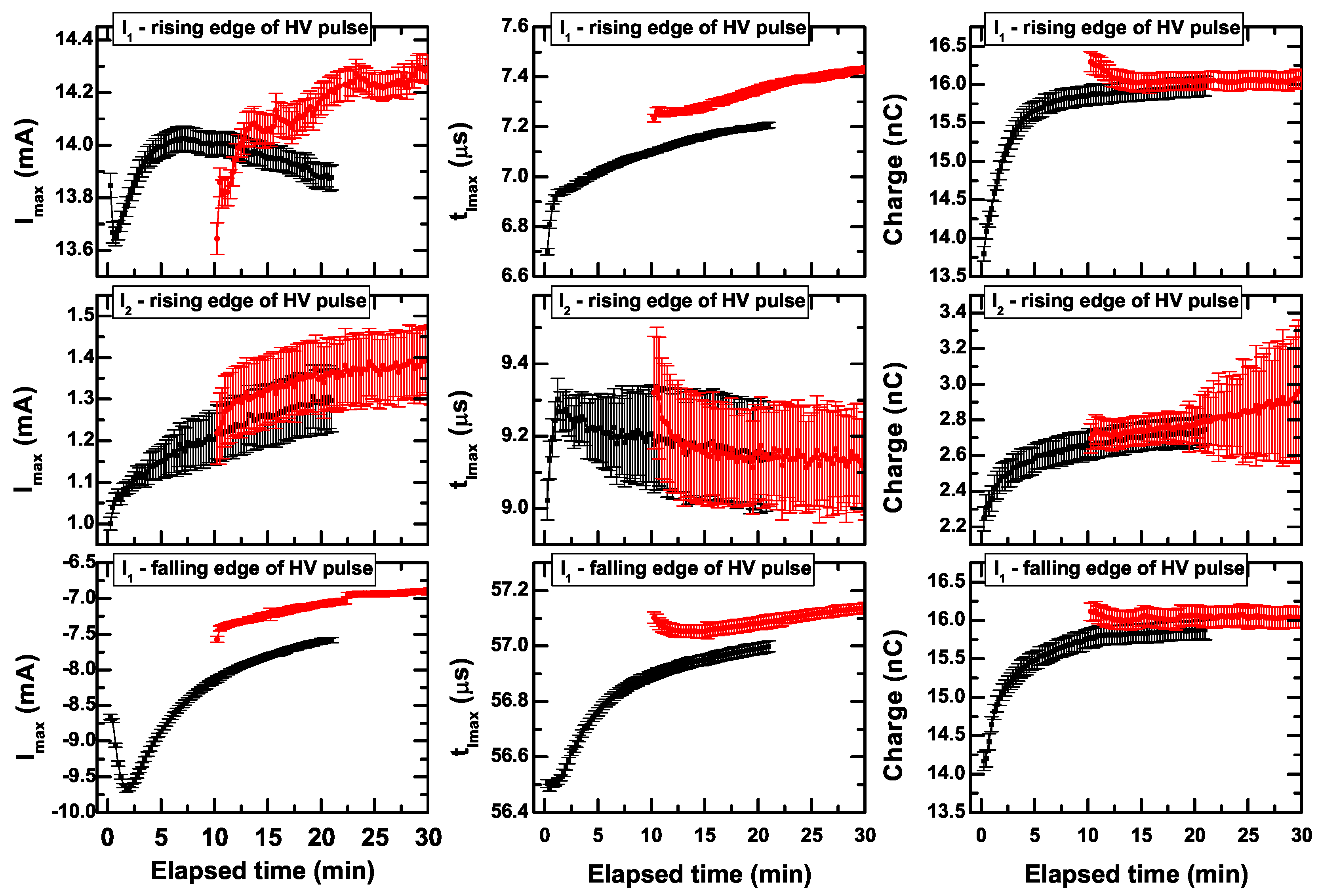
Discharge monitoring immediately after ignition, using the FastFrame (TM) acquisition mode launched every 15 s, shows the existence of a specific settling time to reach a quasi-stationary working regime, as observed for the time behaviour of all studied electrical parameters (
Figure 3). For example,
, the gap current, measured in the external circuit, is the result of electrical phenomena occurring inside the dielectric tube. During the first 10 min from plasma ignition, we observed a decrease of
current peaks, for both rising and falling edges of the HV pulses, followed by an increase and a transition to a steady state value. This can be attributed to few significant factors: a decrease of electric field applied to the flowing gas, due to charge accumulation on tube inner surface over multiple discharge events; generation of a conduction channel, that provide an electrical connection with outside plasma jet; built-up of excited and metastable species in the helium channel over multiple discharge events. Using time-resolved local electric field measurements, a similar behaviour was observed for a plasma jet impinging on a dielectric surface, in different configuration and very different time scale [
29]. This was called initialization of the plasma jet and a net transition from branching streamers to guided streamer was pointed [
29,
30].
Contrary, the
(plasma jet current at nozzle exit) peak presents very low values, around 1 mA and we observed an increase of about 33% of initial value. This can be attributed to the flow stabilization outside the dielectric tube and air molecules mixing with the rare gas. By turning on the gas flow 10 min prior to HV pulses launch (red symbols in
Figure 3), we observe that parameters of the plasma jet current at nozzle exit are overlapping with the same parameters for the case when the gas flow and the HV pulses are turned on simultaneously (black symbols in
Figure 3). Notably, the total transported charge during discharge events saturates quickly, after approximately 5 min (
Figure 3, right side column).
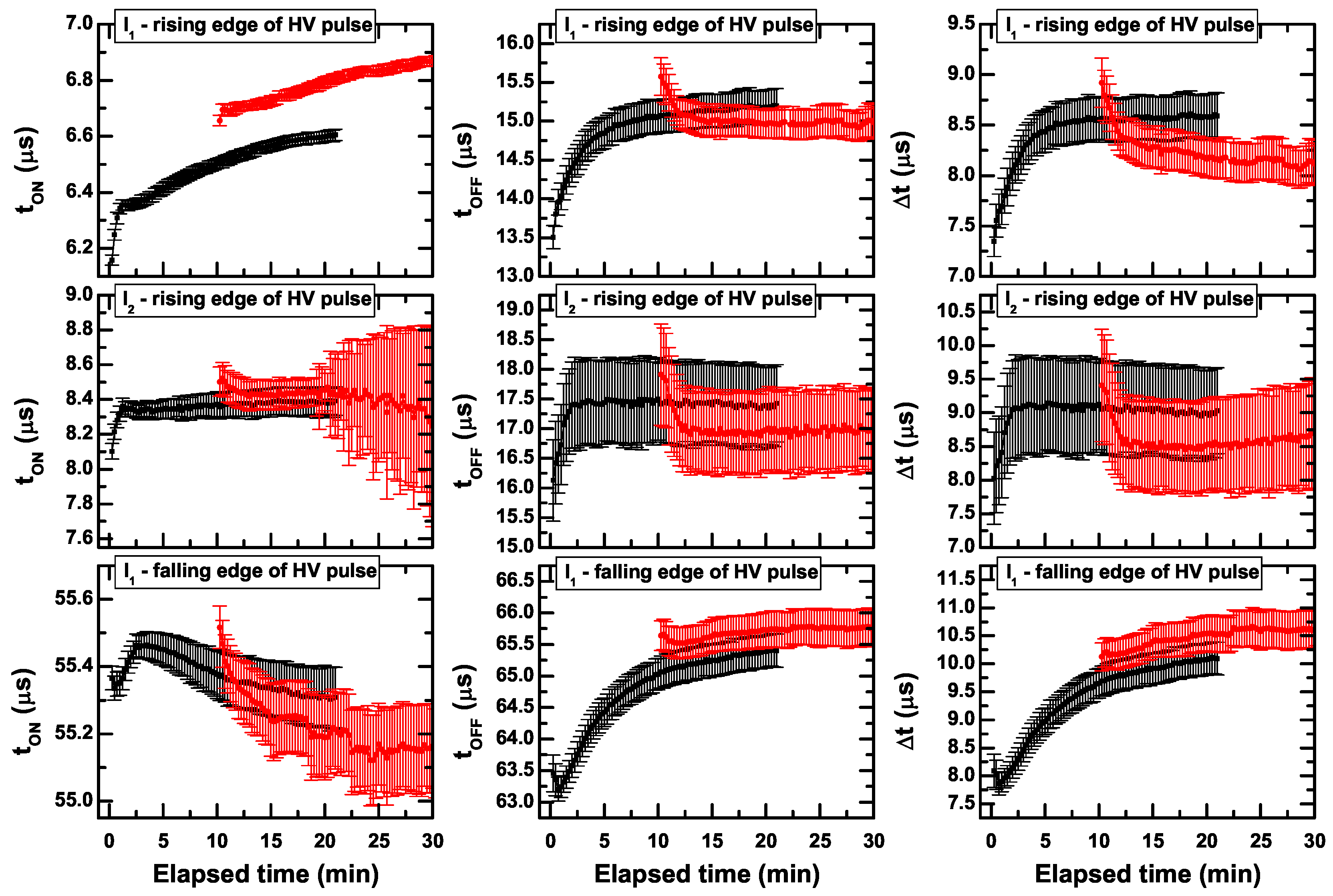
Similar behaviours was found for all characteristic times of current pulses (ignition time, peak current time and extinction time) during the monitoring period (
Figure 4). The duration of current peaks was found to be comparable (between 7.5–10
s) for
and
current peaks observed for the rising edge of HV pulses. A slight increase of
was observed from 7.3 to 8.5
s and for
from 8.0 to 9
s. A higher duration (10
s) of discharge events during falling edge of HV pulses was observed for
. No significant variations of these parameters where observed in the gas flow in turned on 10 min prior to HV pulses launch (red symbols in
Figure 4), excepting the start-up time of
observed for the rising edge of HV pulses.
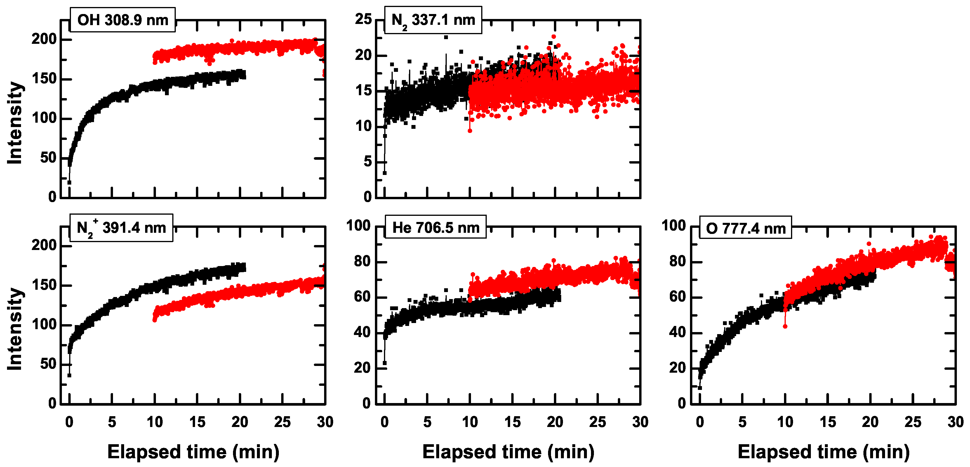
Transitions between electronic states of atomic species (e.g., He, H and O) are observed as lines in the jet’s emission spectrum, while spectral bands are originating from rovibrational transitions of small molecules such as N
2, N
2+ and OH. The increase of HV pulse frequency induces an increase of all lines and bands in the emission spectrum, while the increase of HV pulse amplitude induces only a slight modification of emission intensity. In order to follow the changes in the level of impurities, selected bands and lines were monitored during the plasma jet warm-up period and the integral intensity is plotted over elapsed time in
Figure 5. The helium and molecular nitrogen emission intensity changes within only few percent, while the emission intensity of nitrogen molecular ion, oxygen and hydroxyl radical seems to follow the same dynamics as the electrical parameters (i.e., maximum current, charge), their production being in close relation to plasma parameters, such as electron density and temperature, but also with the molecular composition of the gas channel. If the gas flow is turned-on 10 min prior the HV pulses launch, we observed a significant modification in the emission intensity of nitrogen molecular ion and hydroxyl radical (red symbols in
Figure 5).
Although, this initial warm-up period of the plasma jet may look normal, it very important to study its characteristics and characteristics times in order to obtain reproducible results during various life science applications of this plasma jet type. Thus, the precise dynamics and stabilisation time must be studied for each specific plasma source and it should be specified as a technical parameter.
3.2. Plasma Source Quasi-Stationary Working Regime
After a certain characteristic time, all monitored electrical and temporal parameters reach a quasi-stationary value. This working regime can be used to rationally explore the discharge current scaling with plasma source operational parameters. Nevertheless, this returns a large data set of numerical value for all monitored electrical and temporal parameters, as they nonlinearly depend on HV pulses amplitude, duration, frequency and polarity (explored intervals are mentioned in
Table 1, average values from 512 discharge events). For both positive and negative polarity HV pulses, the following general trends were observed: the increase on the HV amplitude induces an increase in intensity for all currents and the total transported charge as well; plasma jet current tends to saturate; shorter HV pulses induces higher currents; higher frequency of the HV pulses strongly reduces the total transported charge, the gap current (
) and increases the plasma jet current (
). The time corresponding to the peak current and ignition time decreased with both HV pulse frequency and amplitude increase, while the extinction time remains almost constant. For most parameters the SD of normal distribution is larger for
peak current, due to dynamic regime of gas flow and mixing with air impurities outside dielectric tube.
Numerically, the extreme values of all measured parameters during the variation of all operational parameters (
Table 1) are presented in
Table 2.
The total transported charge agrees very well with similar experimental observations of the actual charge deposited on a liquid or solid target [
31,
32]. The average values of power dissipated during the plasma jet development for a single current pulse are of watt order, for all parameters studied here, while the energy dissipated during a single current pulse is of few tens of microjoules order. These values are in agreement with previous computational results [
33] which shows that around 70% of the total energy is dissipated by plasma electrons, while most of the remaining energy could be dissipated by plasma ions. Electric field measurements using spectroscopic measurements returns values of around 20 kV/cm along the along the outside plasma jet [
34], consistent with the time resolved measurements using Pockels effect based probes [
35].
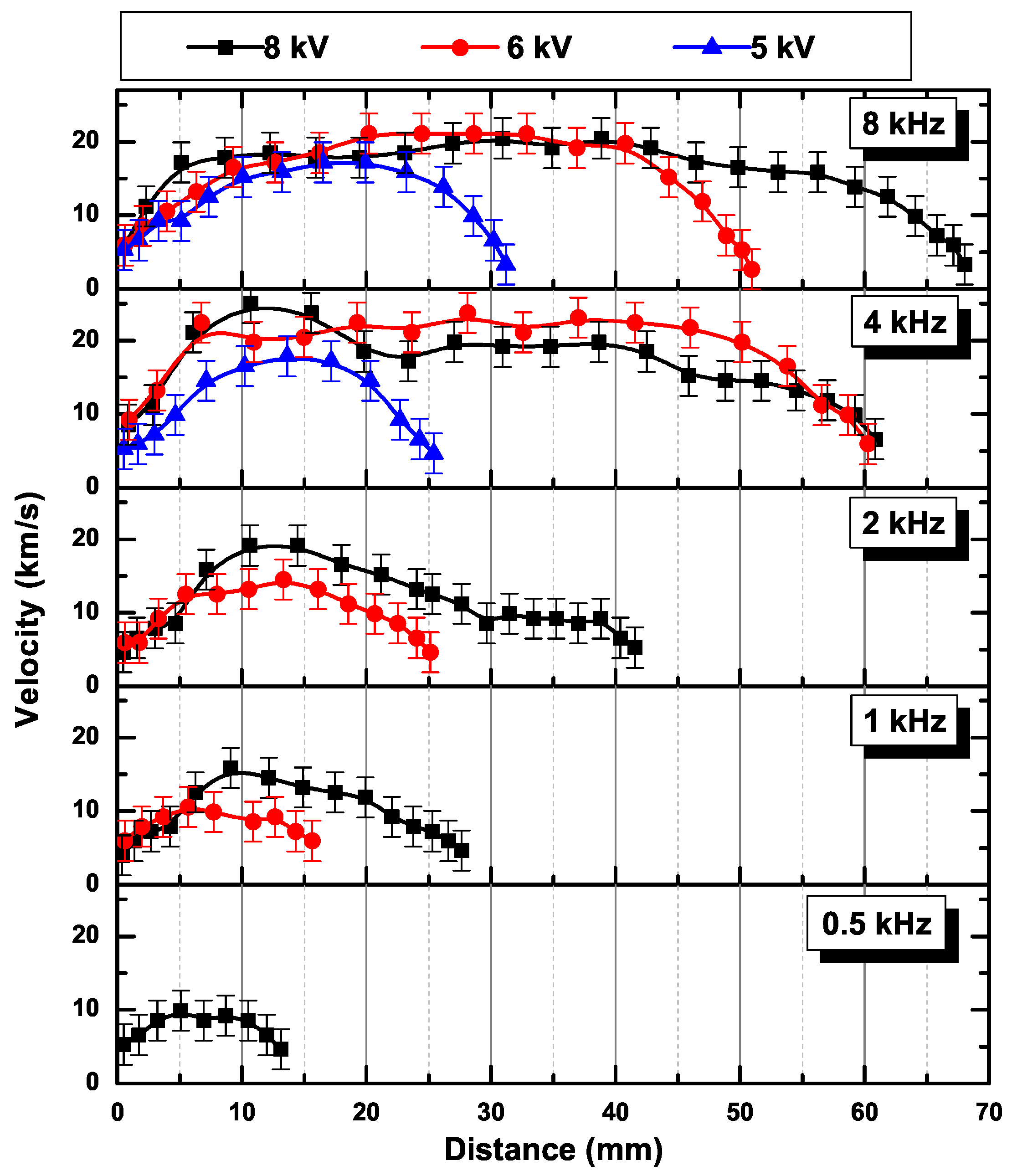
The delay observed between the peak current for
and
can be used to calculate the value of the ionization front propagation speed [
36,
37]. For example, using the time value corresponding to peak current (
, 50
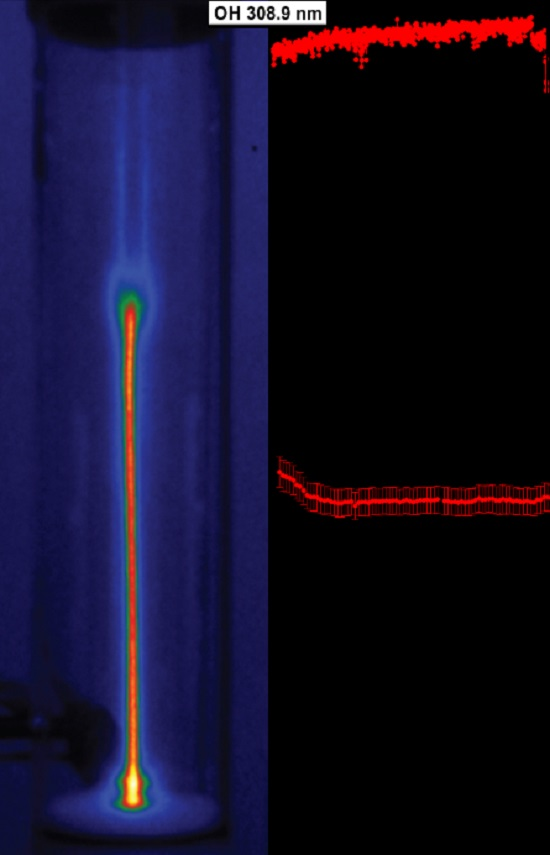
s duration of HV pulses, positive polarity), we obtain the following: 8 ± 0.5 km/s for 4 kV, 16 ± 2 km/s for 6 kV and 8 kV; there was no statistically significant variation function of HV pulse frequency, in the investigated range. It should be mentioned that these are spatially averaged values, over the current probe width (i.e., 25.4 mm). Nevertheless, these values match very well with the streamer head propagation speed, as obtained from the ICCD imaging of guider streamer head (
Figure 6), in the nozzle exit region. The values returned by both methods are much larger than the gas flow velocity, i.e., 4.18 m/s for our geometry and flow conditions. The gas flow rate and the consequent gas flow velocity in fixed geometry is a parameter that correlates with the length of the plasma jet, impinging the free air [
38,
39].
The advantage of ICCD imaging was the possibility to study the guided streamer head propagation over relatively long distances from nozzle exit, with a high spatial resolution. We were able to point in this way that, for constant flow rate conditions and fixed electrode arrangement, the length of the outside jet depends on the frequency and amplitude of the driving high voltage pulses (
Figure 6). Supplementary, it has been demonstrated in a number of recent studies, that this characteristic dimension of the outside plasma jets in helium is also influenced by the electrodes dimensions and constructive details [
40,
41], gas flow rate [
38,
42,
43,
44], dielectric tube diameter [
45,
46,
47].
For all studied parameters, we observed an acceleration of the streamer head after leaving the dielectric tube, followed by an acceleration free region and a deceleration in the plasma jet tip region. These three distinct phases of the guided streamer head, during its travel through ambient air, may be also considered as launching (with increasing velocity), propagation (roughly constant velocity) and ending/landing (in mid air or upon a surface, with decreasing velocity) [
48,
49,
50].
The main processes in weakly ionized plasmas are the charge-neutral interactions, as all other electrostatic interactions have a minor contribution. More specifically, electron impact processes (e.g., electron impact excitation, dissociation or ionization) are dominant reactions in the plasma volume and at interfaces with soft materials. Thus electron density and gaseous environment are of major importance for the physics and chemistry of plasma jets.
Based on the Ohm’s law for the electron current in the plasma column generated in similar plasma devices, an estimation of the electron density can be achieved [
51,
52,
53]. This is valid for a conductor with homogenous distributed charge over transversal cross section (i.e., negligible radial charge transport) and constant diameter (
D) in the evaluated region. Actually, if the diameter of the plasma jet charge region is considered to be equal to the luminescent region, we can only accurately estimate the product between the maximum electron density (
) and electron drift velocity (
):
where
e is the electron charge.
Using Equation (
1) and assuming that value of the axial electron drift velocity can be roughly approximated by the streamer head velocity, for
values in range 0.2 to 1.6 mA, electron density values between 0.6 to
cm
are obtained. This leads to typical order of magnitude for the ionization degree of
, emphasising strong differences in comparison with low pressure discharges. These values are in general underestimated in comparison with other measurements such as Stark broadening of hydrogen lines [
54], Thomson scattering of laser radiation [
55,
56] or Rayleigh microwave scattering [
57], mainly due to difficulty of finding correct values for drift velocity. Although the electron density estimation from plasma column current monitoring is only a rough method, other issues related mainly to experimental design of the plasma sources must be considered in order to compare experimental results. For example the technical solutions employed by various research groups to generate the helium atmospheric pressure plasma jet are sometimes very different (i.e., internal or external electrodes, HV pulse shape and rise time, gas mixture, etc.), inducing inherent variations of all plasma parameters, including electron density. Moreover, the space and time dependent electron density values and the various technical solutions are leading to a broad range of values, from
to
cm
.
3.3. Influence of a Third Electrode
The neutral gas composition of the helium plasma jet and the positive or negative ions populations were studied using molecular beam mass spectrometry. In order to sample the plasma jet phase, the jet assembly axis was aligned with mass spectrometer axis, keeping a constant distance of 10 mm between the dielectric tube nozzle and the first cone of the mass spectrometer, containing the sampling orifice. This metallic component, biased function of the selected analysis mode, acts as a third electrode and becomes part of the equivalent electrical circuit. Thus, we observed significant variations in the peak values of
current, for the selected parameters to operate the plasma jet during mass spectrometry analyses (i.e., HV pulse amplitude 6.5 kV, 4 kHz frequency, 50
s duration, positive and negative polarity). More precisely, for positive polarity high voltage pulses the peak value of
current during the rising edge is now around 10 mA (compared with 0.96 mA for the free plasma jet) and we were also able to detect an
current of around
mA peak value during the falling edge. For negative polarity high voltage pulses we observed an
current of around
mA peak value during the falling edge and the peak value of
current during the rising edge is now around
mA (compared with 0.93 mA for the free plasma jet). This very different behaviour of free plasma jets and plasma jets impinging on conductive targets was argued by some groups, including us [
58,
59,
60,
61,
62,
63].
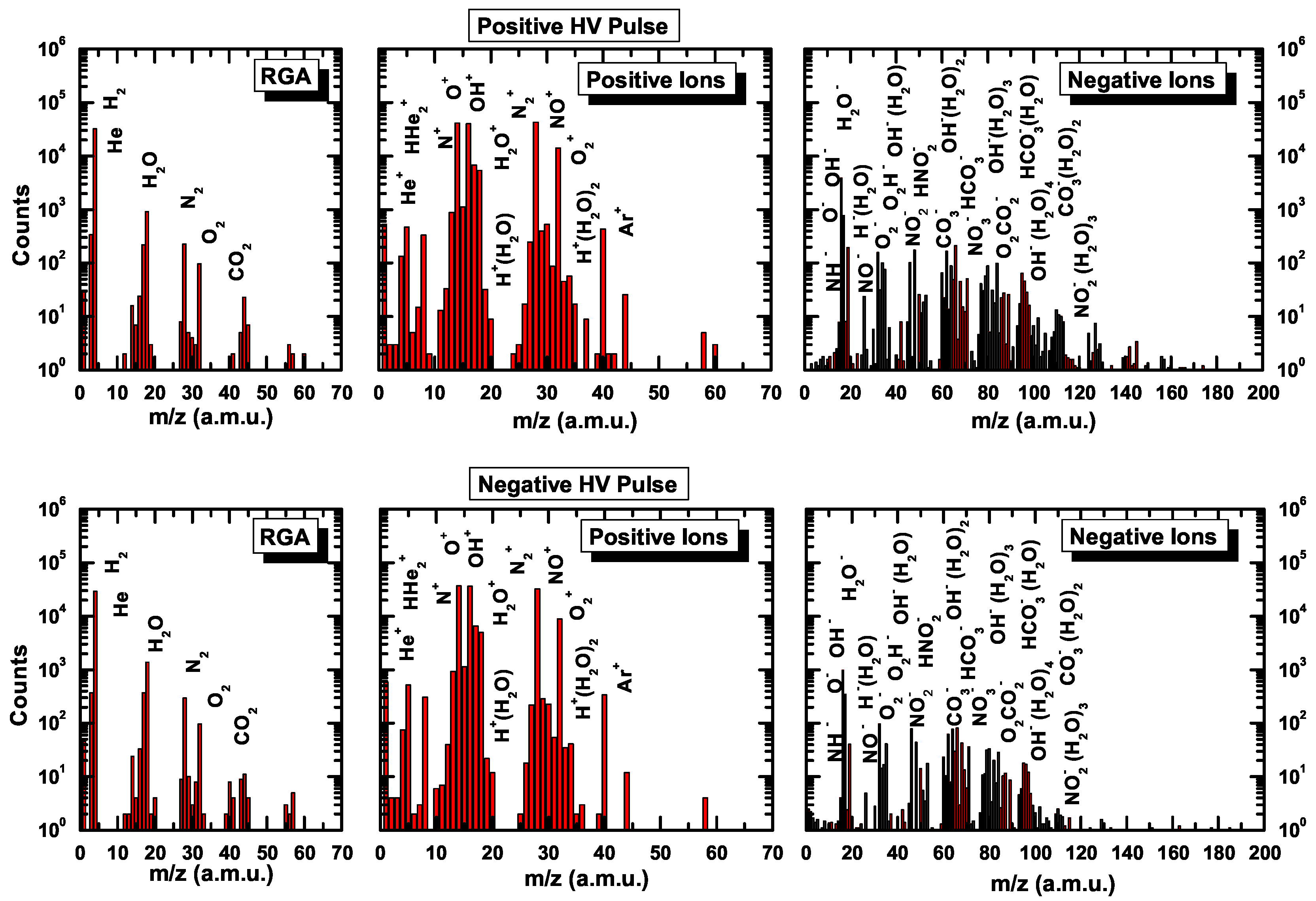
Figure 7 shows the mass spectra of the plasma source under investigation, using both residual gas analysis mode and ions analysis modes. The residual gas analysis spectrum reveals the presence of air traces in the plasma source effluent, signatures around the following mass numbers being found in the residual gas analysis (RGA) spectra of the plasma jets, driven by both positive and negative polarity HV pulses:
= 4 (He),
= 18 (H
2O),
= 28 (N
2),
= 32 (O
2), and even
= 44 (CO
2).
The negative ions spectrum is dominated by oxygen species, in atomic form, = 16 (O−) or homonuclear molecules form, = 32 (O2−) and = 48 (O3−). Heteronuclear molecules of oxygen with H, N and C are observed at the following mass numbers: = 17 (OH−), = 30 (NO−), = 33 (O2H−), = 46 (NO2−), = 47 (HNO2−), = 60 (CO3−), = 61 (HCO3−), = 62 (NO3−) and = 78 (O2CO2−) . At relatively high mass numbers, up to 150 amu, water based clusters around OH−, O2−, O3−, NO3−, CO3−, HCO3− core ions are observed.
The positive ions spectrum is less abundant in species and contains signatures at = 1 (H+), = 4 (He+), = 14 (N+), = 16 (O+), = 18 (H2O+), = 19 (H+(H2O)), = 28 (N2+), = 30 (NO+), = 32 (O2+), = 37 (H+(H2O)2), = 40 (Ar+), = 44 (CO2+).
Congruent results, concerning the ambient impurities present in the discharge effluent, were also reported by other research groups for various types of atmospheric pressure plasma jets [
18,
19,
20,
21,
64]. This rich ion chemistry is only due to air impurities diffusion in the rare gas channel and it may be modified for desired applications if small amounts, less than 1% of additional gases (e.g., O
2, N
2, CO
2 or H
2O), are mixed with the main working gas.
Only small changes are visible in the time averaged mass spectra by changing the HV pulses polarity. For example, if positive polarity HV pulses are used to drive the plasma jet, the negative ions mass spectrum shows contributions at mass numbers higher than 120 amu, associated with a large number of water molecules present in the hydrated shell.
4. Conclusions
Atmospheric pressure helium plasma jets represent appropriate technical solutions as plasma sources for life sciences, especially in applications involving local treatments. They present advantages such as relatively reduced dimensions of the set-up, easy to handle and to integrate in already existing set-ups for biological studies, gas temperature values equal or close to room temperature, pulsed regime allowing between the short duration individual discharge events a relatively long free radical chemistry period. Through the variation of the HV pulse parameters, electrical parameters of the plasma source and consequent plasma jet electrical parameters (e.g., charge density, mean electron energy) and geometric characteristics (i.e., external length, diameter, total volume) can be influenced and controlled for various life science applications.
Using appropriate timing of the experiment and the series of electrical data for multiple consecutive discharge events, we observed the transition to a quasi-stationary working regime of the plasma source. Moreover, we observed that all electrical and temporal parameters related to the gas breakdown during single discharge events are characterized by a normal distribution over multiple consecutive discharge events. The discharge current scales with a broad range of electrical operational parameters (i.e., HV pulses amplitude, frequency, duration and polarity). Supplementary parameters such as distance to target, gas mixture and flow characteristics or shield gas should be used along with the parameters discussed in this paper to rationally explore and design helium plasma jet medical devices.
The monitoring of the plasma source was enlarged using optical emission spectroscopy, high speed imaging and mass spectrometry observations, in order to obtain data that may serve to understand the plasma source operation for specific applications in life sciences. The results can be used in modelling and simulation scenarios in order to get a better insight into specific processes, inducing a positive response in clinical or laboratory applications of the helium plasma jet.


 ,
, 


