Laser Irradiation Responses of a Single-Crystal Diamond Produced by Different Crystal Growth Methods


Department of Mechanical Engineering, Keio University, Hiyoshi 3-14-1 Kohoku, Yokohama, Kanagawa 223-8522, Japan
*
Author to whom correspondence should be addressed.
Appl. Sci. 2017, 7(8), 815; https://doi.org/10.3390/app7080815
Submission received: 18 June 2017
/
Revised: 3 August 2017
/
Accepted: 7 August 2017
/
Published: 9 August 2017
(This article belongs to the Section Materials Science and Engineering)
Abstract
:Responses of two types of single-crystal diamonds, prepared by chemical vapour deposition (CVD) and high pressure high temperature synthesis (HPHT) methods, respectively, to a nanosecond pulsed neodymium-doped yttrium aluminium garnet (Nd:YAG) laser were investigated and compared. It was found that due to the difference in the transmission rate and refractive index, the laser-induced surface/subsurface features of the two types of samples were distinctly different. For the CVD sample, destructive interference takes place on the upper surface, leading to direct ablation of smooth grooves with deposition of graphite. For the HPHT sample, however, laser-induced grooves were formed on the reverse side of the irradiation surface (namely, the lower surface) at certain laser fluences due to the constructive interference phenomenon of the laser and the high refractive index of the material. The reverse-side irradiation resulted in the formation of deep and sharp grooves with rough bottoms and insignificant deposition of graphite on the area surrounding the groove. The machining thresholds for the upper and lower surfaces of both types of diamonds were experimentally obtained and theoretically verified. The findings of this study provide important process criteria for laser machining of different kinds of diamonds. The reverse-side irradiation method enables efficient machining of deep grooves in diamonds using a lower power laser.
1. Introduction
Diamond is an important material having various applications, ranging from cutting tools to heat spreaders in light emitting diodes (LEDs) [1,2], due to its remarkable hardness, thermal conductivity and chemical inertness [3,4,5]. These properties, however, combined with its high brittle nature, make diamond incredibly difficult to machine by conventional mechanical methods. Diamond cannot be cut with a diamond tool, obviously. Grinding with a diamond wheel and polishing with diamond abrasives are possible but extremely time-consuming, especially for micro groove channel fabrication. Thus, discovering an efficient method to process diamond has been the goal of many interdisciplinary studies. Recent investigations have shown that laser irradiation is one such method [6]. Irradiation causes the appearance and continuous growth of a graphitized region at low fluences, which is easily and rapidly ablated at higher fluences [7]. Some researchers have utilized this phenomenon to machine graphitic wires in bulk diamond [8]. As a non-contact method, laser processing results in no tool wear and has high geometrical freedom. Recent studies have found that different types of structures can be machined. Through the use of short pulses, high precision and sharp profiles can be achieved [7,9], as heat conduction into the bulk material is significantly reduced [10]. The machining of curved profiles with micron-sized curvatures has also been shown to be possible by the use of femtosecond pulses and an accelerating beam [11]. In addition, laser irradiation was found to result in laser-induced periodic surface structure on diamond film, explained by interference between the incident laser and surface scattered wave [12,13]. In a previous study of the present authors, it was discovered that nanosecond pulsed laser irradiation was also useable for microgrooving of diamond and produces four types of groove formation mechanisms for chemical vapour deposition (CVD) diamond [14].
Artificial diamond is produced mainly by two methods, chemical vapour deposition (CVD) and high pressure high temperature synthesis (HPHT). Different crystal growth methods may result in different lattice structures and defect distributions. Diamond crystals grown by CVD are bombarded by energetic particles during their synthesis, which results in the generation of different irradiation-induced defect centres or neutral lattice vacancies. These are identifiable by electron paramagnetic resonance (EPR). CVD diamond has several exclusive defect centres, labelled KUL3-6, which are not detected in HPHT samples [15]. In addition, CVD diamond is known to contain significant densities of hydrogen, oxygen, nitrogen, boron and silicon impurities. In contrast, HPHT rarely contains silicon impurities but contains high levels (10~100 ppm) of nitrogen impurities, causing it to appear yellow in colour [16]. The lattice structure also differs. CVD diamond contains a small amount of sp2 bonds which can usually be detected as a peak between 1350 and 1600 cm−1 in Raman spectroscopy [17]. This peak is not observed in most HPHT diamond samples. The aforementioned differences affect the diamond’s optical properties, which should affect the diamond’s responses to laser irradiation and the machining phenomena. However, up to now, there is no available literature on the laser irradiation characteristics of diamond crystals grown by different methods.
Thus, in this study, laser irradiation has been performed on two different types of diamonds, one created by CVD and another created by HPHT synthesis. The difference in irradiation marks and subsurface damage were observed, and the mechanisms which may have caused these differences were considered. In doing so, the process criteria and optimal conditions for laser machining of diamond can be established. This study is one of the first to investigate and compare, both experimentally and theoretically, the laser irradiation characteristics of the two types of diamonds.
2. Materials and Methods
The experimental set-up is schematically shown in Figure 1. The laser used in the following experiments was a neodymium-doped yttrium aluminium garnet (Nd:YAG) laser pumped by a laser diode, LR-SHG (low-repetition second harmonic generation), from MegaOpto Co., Ltd (Saitama, Japan). It has a maximum power output of >1 W, a wavelength of 532 nm and a spot diameter of 85 μm. The laser output energy has an approximate Gaussian distribution. The laser beam was controlled using a galvanometer scanner system with a Miramo controller GMP-507005 made by Y-E Data Inc. (Saitama, Japan). Laser motion programs were created using GmcLib.DLL 2.0 software provided by Y-E Data Inc., and FFFTP (file transfer protocol) software developed by Sota & cooperators (Izumo, Japan) was used to download these programs to the galvanometer scanner system. The laser beam was focused onto a workpiece stage using an f-theta lens. The diamond sample was placed on a base with an opening so that the lower surface of the diamond was not in contact with the stage surface. The laser parameters used are shown in Table 1.
The CVD diamond was a rectangular sample with dimensions of 4 × 3.5 × 1.10 ± 0.02 mm. The HPHT diamond was also a rectangle, sized 3 × 3 × 1.10 ± 0.02 mm. Both had flat, polished surfaces and the irradiated surface was the (100) Miller surface (all the other faces also had an equivalent crystal orientation). The surface roughness of these samples was Ra = 1.8 ± 0.6 nm for the CVD sample and Ra = 0.4 ± 0.1 nm for the HPHT sample.
As the transparency of these materials is very important for laser processing, we measured the transmission rate of each sample. Measurements were performed at four different locations on the sample to ensure that they were similar and so that local disparities would not affect the results. The transmission rate was obtained by measuring the raw laser power by a 3-sigma single-channel laser power meter produced by Coherent Inc. (Santa Clara, CA, USA) followed by another measurement with the diamond sample above the power meter, then taking the ratio of the two.
To detect the laser-induced phase transformation of diamond, Raman spectroscopy of the samples before/after laser processing was performed by a laser micro-Raman spectroscope NRS-3100 (JASCO Corporation, Tokyo, Japan). To remove the laser-induced debris, the samples were then cleaned using a chemical cleaning process. The samples were placed in a solution of nitric, sulphuric and perchloric acid (in a volume ratio of roughly 1:5:3) and heated to ~200 °C. After cleaning, they were observed using the VHX-1000 optical digital microscope (Osaka, Japan) made by KEYENCE, the Inspect S50 Scanning Electron Microscope (SEM) (Hillsboro, OR, USA) made by FEI Company for higher magnifications, and the MP-3 laser probe made by Mitaka Kohki Co., Ltd. (Mitaka, Japan) to measure groove depth.
3. Results
3.1. Groove Formation Behaviour
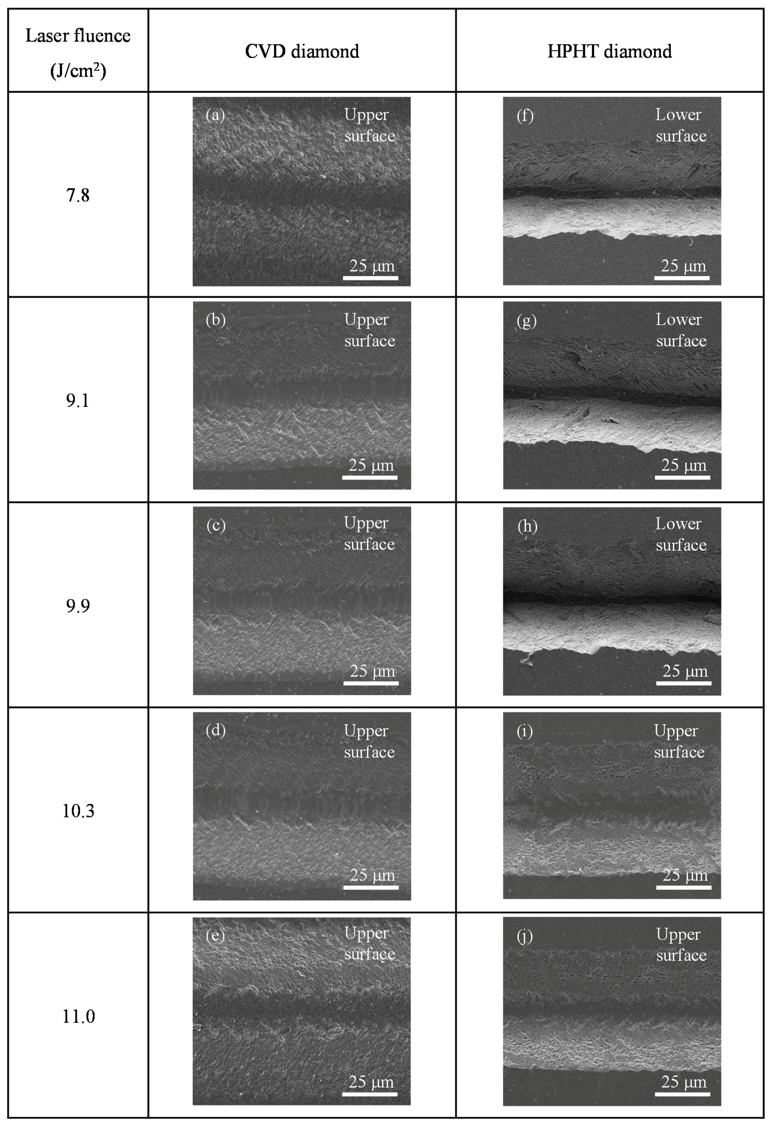
First, laser irradiation was performed on CVD diamond and the irradiated surfaces were examined. Irradiating the CVD samples with a fluence of around 14.0 J/cm2 caused sample breakage, so the fluence was limited to below 11.5 J/cm2. Grooves were found only on the surface on which the laser was incident (upper surface) and the bottom of the grooves was smooth, as presented in Figure 2a–e.
Next, laser irradiation was performed on the HPHT sample. The HPHT diamond could not be machined with a laser fluence below 7.0 J/cm2. Interestingly, at fluences below 10.3 J/cm2, the irradiation-induced grooves, as shown in Figure 2f–h, were found on the reverse side of the sample surface that was being irradiated (lower surface), whereas no marks were found on the upper surface. This phenomenon will be referred to as reverse irradiation in this paper. At fluences equal to or greater than 10.3 J/cm2, a groove was machined onto the upper surface on which the laser was incident (referred to as forward irradiation), as presented in Figure 2i,j while no grooves were found on the lower surface.
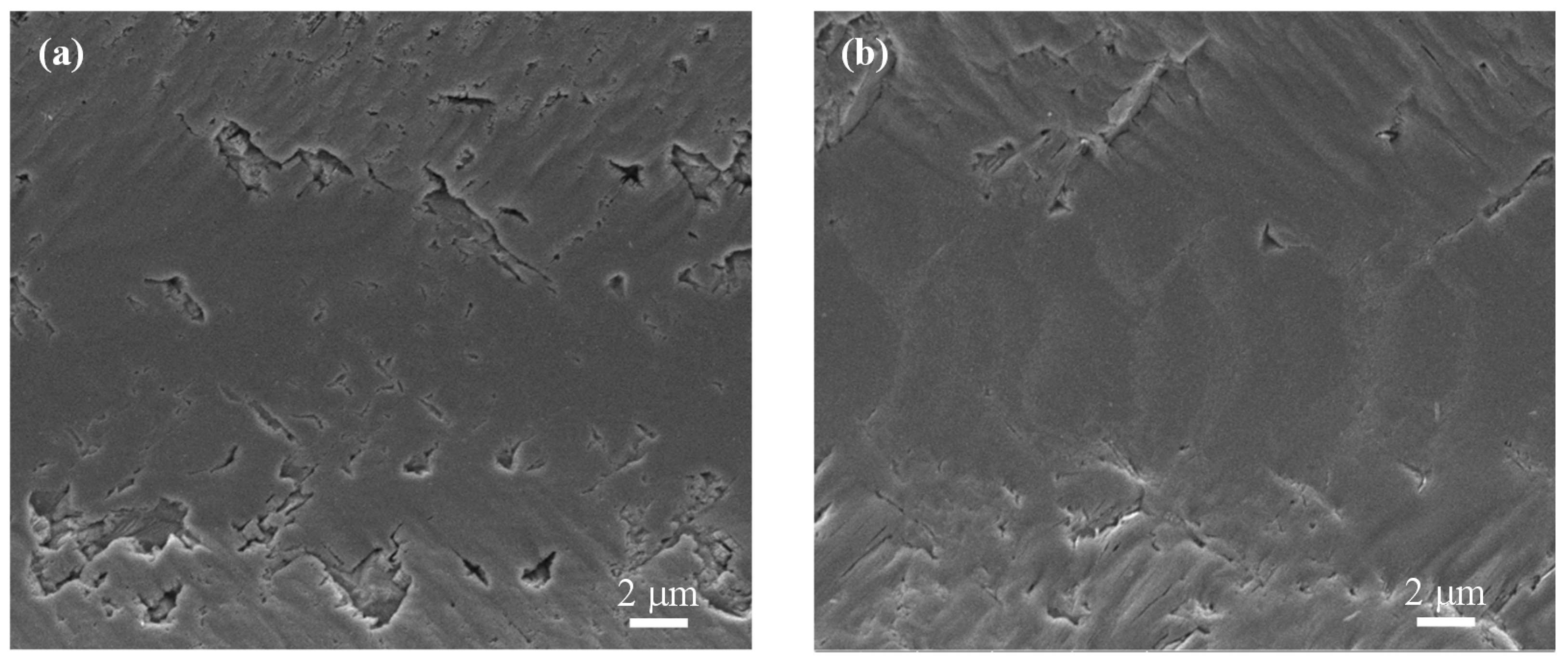
The surfaces of the grooves were further compared in detail. The SEM images of Figure 3 indicate similarities between the grooves formed on the upper surface of HPHT diamond and the grooves on CVD diamond. They both possess a crack-free groove centre. On the other hand, Figure 4 shows the rough, jagged surface of the grooves found on the lower surface of HPHT diamond. Thus, by comparing Figure 3 and Figure 4, the grooves obtained by forward and reverse irradiation are shown to be clearly different.
3.2. Groove Cross-Sectional Profile
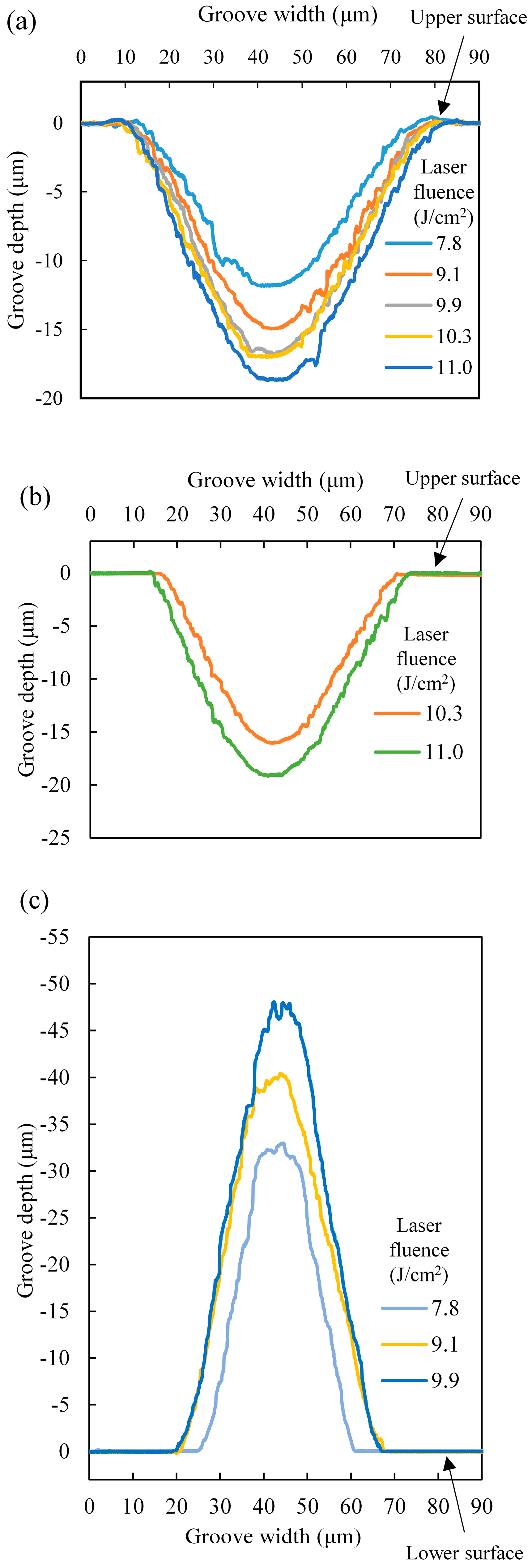
The cross-sectional profiles of each groove were examined. As a general trend, groove depth increases with laser fluence for both diamonds. For the grooves on the CVD sample, the cross-section of the grooves represents a smooth curve as shown in Figure 5a. For the grooves on the HPHT sample, shown by the cross-sectional profiles in Figure 5b,c, two different regimes can be observed. For the grooves machined onto the lower surface at low laser fluences, the profiles were sharp and narrow and possessed a slightly jagged structure at the groove bottom, whereas for the grooves machined onto the upper surface at high fluences, a shallower smoother curve was obtained, similar to those machined on the CVD sample. This shows that it is possible to machine deep and narrow grooves with a high aspect ratio using a low laser power through reverse irradiation, without any effect on the upper surface.
3.3. Debris Cloud Formation
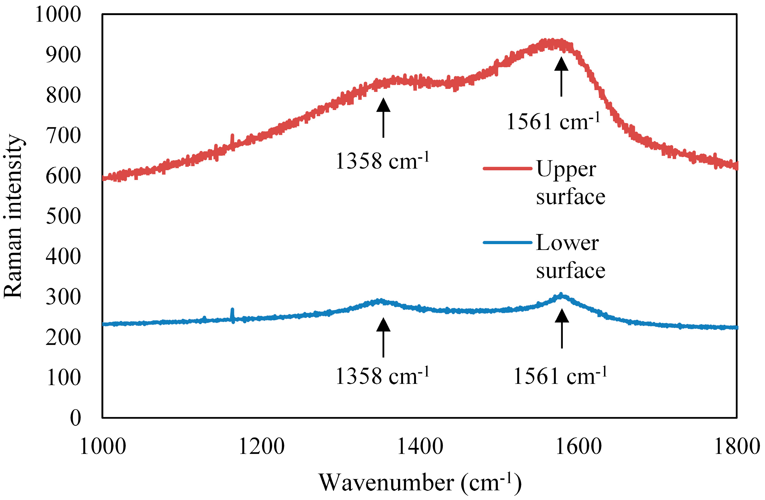
It is noteworthy that dark clouds of debris were formed around the grooves on the upper surfaces of both CVD and HPHT diamond samples, as shown in Figure 6. The composition of the debris was determined by Raman spectroscopy, shown in Figure 7, to contain sp2 bonds, indicated by the peak at 1561 cm−1. However, no such debris cloud was observed on the lower surface of HPHT diamond formed by reverse irradiation. The surface around the groove was clean. When investigating the grooves on the lower surface of the HPHT sample with Raman spectroscopy, no sp2 bonding was detected and only a peak at 1331 cm−1 was found, indicating the presence of diamond.
4. Discussion
4.1. Machining Thresholds
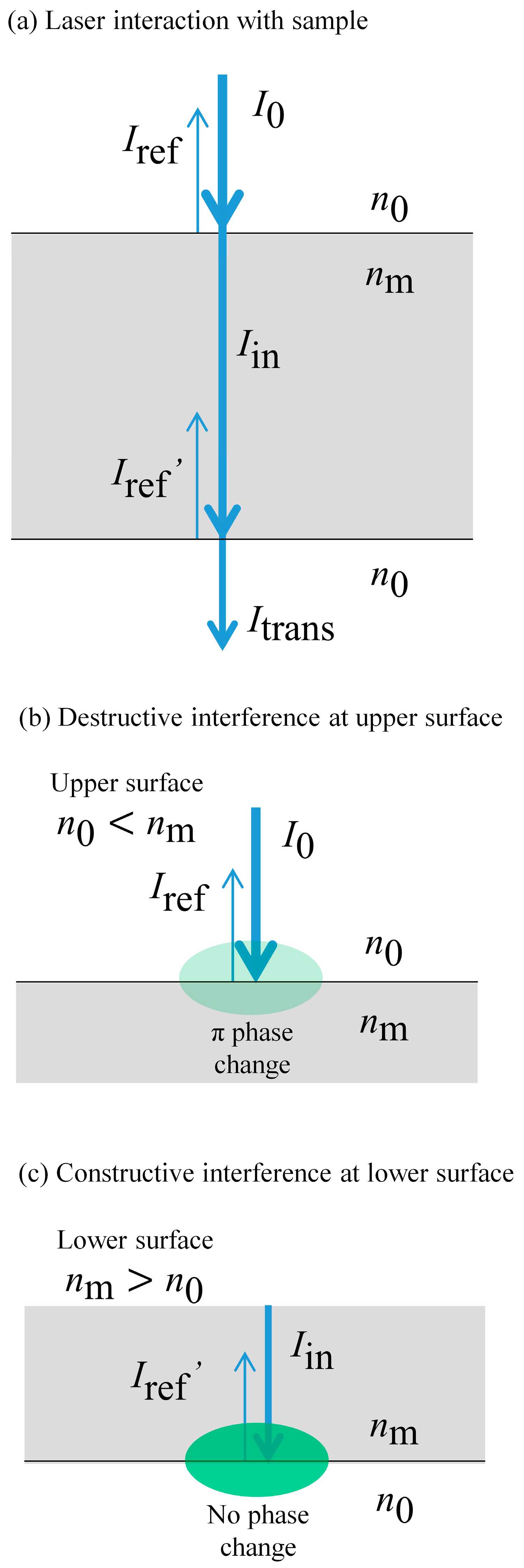
As the Rayleigh length of the laser is 10 mm and far greater than the thickness of the sample (~1 mm), the beam radius is approximately constant throughout the sample; it is 42.5 μm on the upper surface and 42.7 μm on the lower surface. Thus, the laser fluence is approximately constant on both surfaces of a given sample. The grooves are thought to have formed on the lower surface due to constructive interference on said surface. To describe this phenomenon in detail, it is assumed that laser absorption within the sample is extremely small and only first-order reflection is considered. Single-crystal diamond is known to be quite transparent at the wavelength used. However, some local absorption occurs due to the presence of crystal defects and impurities. Absorption α is calculated as follows:
where t is the transmission rate and r is the reflection rate. The transmission rate of diamond is known to be ~70% and the reflection rate is ~17% [18]. The assumption of a low absorption rate is shown to be applicable as it is roughly 13%. The light passes through the diamond sample as shown in Figure 8. The transmission rates for the samples used, through the 2 surfaces, were 75.7% for HPHT diamond, and 83.9% for CVD diamond respectively.
Using the wave theory of light, the laser intensity I can be described by the following equation.
where K is wave amplitude, E is the electric field strength with E* as its complex conjugate, x is displacement and t is time so that
The initial laser intensity is , where is the initial electric field strength. Additionally, laser light differs from ordinary light in that it produces photons of the same frequency, wavelength and phase [19]. Therefore, it can be assumed that the phase is generally constant. In a Gaussian beam, a phase shift (Guoy phase shift) is present near the beam waist, resulting in an increase in the wavelength. However, it is not observable in most experiments using a fundamental Gaussian beam (which was used in the present study) and only becomes significant for higher-order Gaussian modes [20]. Assuming that the light ray reaches the diamond at normal incidence, the following equations stand true for the upper surface.
where is intensity reflected from the upper surface, is the intensity within the diamond and given that is the refractive index of the diamond and is that of air, the reflectance R can be written as:
At this surface, destructive interference occurs between the incident ray and the reflected ray. This is because the refractive index of air is less than the refractive index of diamond, so that a phase change of π accompanies the reflection [21]. By the principle of superposition, the incident ray and the reflected ray can be combined to give the intensity at the upper surface.
After crossing the upper interface, passes through the diamond to reach the bottom surface. Here, the following equations are used.
where is the intensity reflected from the lower surface and is the intensity transmitted through the lower surface. In contrast to the upper surface, the refractive index change at the lower surface is from high to low. Thus, no phase change occurs and constructive interference takes place. The two intensities and are superposed and the intensity at the lower surface increases.
Moreover, for machining to only take place on the lower surface, the following condition must be met.
where is the intrinsic damage threshold intensity of the material [22]. Next, as the values of transmission, , have been measured, it is possible to calculate R values, as shown in the following equation, and consequently values by rearranging Equation (6).
For the HPHT sample, we obtain = 2.13 and R = 0.13. This n value is in fair agreement with theoretical values; the refractive index of high-quality HPHT diamond is 2.41~2.42 [23,24]. Therefore, the intensity becomes
Intensity is higher at the lower surface, thus machining of the lower surface occurred even at low fluences when no machining occurred on the upper surface. The boundary fluence was 10.3 J/cm2 for upper surface machining and 7.8 J/cm2 for lower surface machining. Taking into account the fact that incident laser fluence is directly proportional to the incident intensity of the laser, , these values resulted in effective threshold values of
where is the machining threshold obtained from the upper surface and is the threshold obtained from the lower surface. As these values are the effective machining threshold of the HPHT sample, they should be equal. However, the lower surface has a lower threshold possibly due to multiple reflections within the sample. The reflections would not result in a phase change and thus constructive interference may occur. This would lead to a greater effective intensity. Additionally, with regards to the machining rate, a deeper groove is machined the lower surface, as shown in Figure 5, possibly due to the fact that there is no plasma shielding. On the upper surface, a plasma would form above the diamond, absorbing the laser and preventing it from reaching the diamond surface. However, on the lower surface, this plasma does not form between the laser and the surface. Thus, no shielding occurs and all energy can be applied to machine the diamond.
In contrast, it must be highlighted that there were no grooves found on the lower surface of CVD diamond. There are several conceivable reasons as to why reverse irradiation did not take place in this case. First, the CVD diamond is not of high quality, as can be seen from the Raman spectrum of its unirradiated surface shown in Figure 9. It is dominated by a peak representing crystal defects, indicated by the peak at 1424 cm−1. As CVD diamond possesses a greater abundance of crystal defects than HPHT diamond, less energy is required to break the diamond structure and the ablation threshold for the upper surface may be greatly lowered. Thus machining may be possible even if destructive interference occurs. Moreover, due to the abundance of crystal defects, which may be non-transparent with regards to the wavelength used, it is possible that the absorption cannot be ignored. In this case, at low fluences, laser energy would be absorbed by near-surface crystal defects and be unable to reach the lower surface.
From the above results and the knowledge that HPHT diamond generally contains more nitrogen while CVD diamond contains more crystal defects, it can be tentatively suggested that these defects contribute more with regards to lowering the ablation threshold.
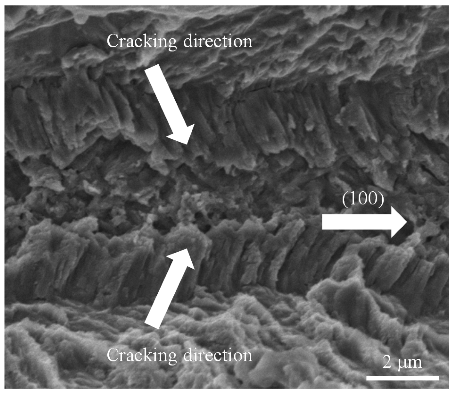
By comparing the groove bottom in HPHT diamond in Figure 3a and Figure 4a, it can be assumed that higher energy at the lower surface caused much spalling due to diamond’s brittle nature, resulting in a rough bottom [25,26]. Material removal appears to be dominated by spalling rather than diamond conversion into graphite and its subsequent sublimation [27]. This is likely to be the reason for the uncharacteristically rough bottom and larger depth. Further evidence is given by Figure 4b, where the roughened bottom of the grooves on the lower surface was observed at a higher magnification. Spalling causes much cracking; as diamond has a cleavage plane at (111), cracking is likely to occur along this plane [28,29]. As the irradiated plane is the (100) plane, and the cracks propagate in a diagonal direction as shown in Figure 10, it may be assumed that the cracks formed primarily along the cleavage plane. The rough walls may be smoothed by the addition of a finishing process using perhaps a weaker laser fluence.
In summary, with regards to the laser irradiation of diamond, the laser intensity is high enough to directly ablate the material from the upper surface at high fluences. In comparison, at lower fluences, the laser passes through the upper surface to reach the lower surface where constructive interference occurs. This interference leads to increased laser intensity and in turn, ablation, causing material removal dominated by spalling from the lower surface. This increase in laser intensity at the lower surface may be applicable to other transparent materials; it has been experimentally confirmed in the laser machining of glass [30].
4.2. Material Structural Change
The above mechanism explains the transition of the groove formation of diamond, but its relation to the sp2 bonded material deposition mechanism must be considered. Laser irradiation is known to cause changes to the crystal structure [31,32,33]. The presence of oxygen in the processing environment is known to greatly reduce the onset temperature of graphitization [34,35,36]. Thus, in order for changes in crystal structure to take place, abundant oxygen is required.
At the lower surface, no sp2 bonding was observed. This may be partially due to the effects of gravity; the ablated non-diamond particles may have been fallen below or may have expanded into the surrounding air. An alternative cause for the limited deposition of particles is that fact that as the laser reaches the surface from inside the diamond sample, and there is a higher probability that it will encounter an inner absorbing center before reaching the lower surface. These absorbing centers have less surrounding oxygen compared to the surface defects. This results in limited graphite production. However, there is some sp2 bonding present within the groove, indicated by peak at 1561 cm−1 in Figure 11. This may be because as ablation occurs on the lower surface, bonds among the surface atoms are broken. This removal of bonded atoms caused re-arrangement of the crystal structure into a more thermodynamically stable state, namely an amorphous or graphitic structure [37].
Figure 11 also indicates that recrystallization due to laser heating did not occur. Narayan and Bhaumik (2015) proposed that the formation of diamond microneedles occurs by recrystallization through the nanosecond laser heating of diamond-like amorphous carbon [38]. In the proposed mechanism, nano-diamonds nucleate and grow rapidly by liquid mediated explosive recrystallization to form microneedles. However, in our study, the area within the groove was found to include sp2 bonds and did not possess a clear diamond peak. Thus, the rough surface can be attributed to spalling rather than recrystallization.
The decrease in deposited sp2 bonded particles, indicated by Figure 7, also agrees with the conclusion that much of the material removal occurred by spalling. Additionally, by comparing groove depth, it can be concluded that spalling has a higher material removal rate compared to the oxidation reaction. In addition, although it may be limited to a certain range to laser fluences, this may be used as a method to machine deep grooves while reducing crystal structure change without additional apparatus or processes.
5. Conclusions
Nanosecond pulsed Nd:YAG laser irradiation has been performed on two different types of diamond single crystals, one grown by CVD and the other by HPHT synthesis. The irradiation marks and surface microstructures were compared. The following conclusions were obtained.
- (1)
- The transmission rate of HPHT diamond to the present laser beam is 75.7%, lower than that of CVD diamond (83.9%).
- (2)
- For both HPHT and CVD diamond, destructive interference takes place on the upper surface at a sufficiently high laser fluence, leading to direct ablation of smooth grooves.
- (3)
- For HPHT diamond, at a laser fluence lower than the machining threshold for the upper surface, laser passes through the upper surface and material removal only takes place on the lower surface of due to constructive interference of the laser, resulting in spalling of material and formation of sharp grooves with rough bottoms.
- (4)
- There is significant deposition of debris containing sp2 bonding on the area surrounding the groove on the upper surface, while no such deposition was found on the lower surface. For the latter, the laser comes into contact with a limited amount to oxygen in the grooves, thus oxidation, which greatly reduces the onset temperature of crystal structure change, cannot take place, and limited sp2 bonds are produced.
The crystal growth method should be taken into account in determination of laser processing conditions. A greater crystal defect density exists in CVD diamond, causing it to become more absorbing and thus easier to machine by lasers.
Author Contributions
Nozomi Takayama conceived, designed and performed the experiments; Nozomi Takayama and Jiwang Yan analyzed the data and wrote the paper.
Conflicts of Interest
The authors declare no conflict of interest.
References
- Konrad, W.; Claus, D.; Marcel, H.; Christian, W. Laser Prepared Cutting Tools. Phys. Procedia 2012, 39, 240–248. [Google Scholar] [CrossRef]
- Plano, L.S.G. Growth of CVD Diamond for Electronic Applications. In Diamond: Electronic Properties and Applications, 1st ed.; Pan, L.S., Kania, D.R., Eds.; Springer: New York, NY, USA, 1995; pp. 61–138. [Google Scholar]
- Tabor, D. Mohs’s Hardness Scale—A Physical Interpretation. Proc. Phys. Soc. Lond. B 1954, 67, 249–257. [Google Scholar] [CrossRef]
- Field, J.E.; Pickles, C.S.J. Strength, fracture and friction properties of diamond. Diam. Relat. Mater. 1996, 5, 625–634. [Google Scholar] [CrossRef]
- Berman, R. Physical Properties of Diamond; Clarendon Press: London, UK, 1965; pp. 140–154. [Google Scholar]
- Konov, V.I. Laser in micro and nanoprocessing of diamond materials. Laser Photonics Rev. 2012, 6, 739–766. [Google Scholar] [CrossRef]
- Dumitru, G.; Romano, V.; Weber, H.P.; Sentis, M.; Marine, W. Femtosecond ablation of ultrahard materials. Appl. Phys. A Mater. Sci. Process. 2002, 74, 729–739. [Google Scholar] [CrossRef]
- Kononenko, T.V.; Komlenok, M.S.; Pashinin, V.P.; Pimenov, S.M.; Konov, V.I.; Neff, M.; Romano, V.; Lüthy, W. Femtosecond laser microstructuring in the bulk of diamond. Diam. Relat. Mater. 2009, 18, 196–199. [Google Scholar] [CrossRef]
- Ramanathan, D.; Molian, P.A. Micro- and Sub-Micromachining of Type IIa Single Crystal Diamond Using a Ti:Sapphire Femtosecond Laser. J. Manuf. Sci. Eng. 2002, 124, 389–396. [Google Scholar] [CrossRef]
- Preuss, S.; Stuke, M. Subpicosecond ultraviolet laser ablation of diamond: Nonlinear properties at 248 nm and time-resolved characterization of ablation dynamics. Appl. Phys. Lett. 1995, 67, 338–340. [Google Scholar] [CrossRef]
- Mathis, A.; Courvoisier, F.; Froehly, L.; Furfaro, L.; Jacquot, M.; Lacourt, P.A.; Dudley, J.M. Micromachining along a curve: Femtosecond laser micromachining of curved profiles in diamond and silicon using accelerating beams. Appl. Phys. Lett. 2012, 101, 99–102. [Google Scholar] [CrossRef] [Green Version]
- Wu, Q.; Ma, Y.; Fang, R.; Liao, Y.; Yu, Q.; Chen, X.; Wang, K. Femtosecond laser-induced periodic surface structure on diamond film. Appl. Phys. Lett. 2003, 82, 1703–1705. [Google Scholar] [CrossRef]
- Rehman, Z.U.; Janulewicz, K.A. Structural transformation of monocrystalline diamond driven by ultrashort laser pulses. Diam. Relat. Mater. 2016, 70, 194–200. [Google Scholar] [CrossRef]
- Takayama, N.; Yan, J. Mechanisms of micro-groove formation on single-crystal diamond by a nanosecond pulsed laser. J. Mater. Process. Technol. 2017, 243, 299–311. [Google Scholar] [CrossRef]
- Iakoubovshii, K.; Stesmans, A. Chemical vapour deposition diamond studied by optical and electron spin resonance techniques. J. Phys. Condens. Matter 2002, 14, R467–R499. [Google Scholar] [CrossRef]
- Lee, K.C.; Sussman, B.J.; Nunn, J.; Lorenz, V.O.; Reim, K.; Jaksch, D.; Walmsley, I.A.; Spizzirri, P.; Prawer, S. Comparing phonon dephasing lifetimes in diamond using Transient Coherent Ultrafast Phonon Spectroscopy. Diam. Relat. Mater. 2010, 19, 1289–1295. [Google Scholar] [CrossRef]
- Wang, Z.Y.; Dong, L.H.; Wang, D.S.; Dong, Y.H. Study of HPHT single crystal diamond as precision cutting tool material. Precis. Eng. 2012, 36, 162–167. [Google Scholar] [CrossRef]
- Mildren, R.P. Intrinsic optical properties of diamond. In Optical Engineering of Diamond; Mildren, R.P., Rabeau, J.R., Eds.; Wiley-VCH Verlag GmbH & Co.: Weinheim, Germany, 2013; pp. 1–3. [Google Scholar]
- Dubey, A.K.; Yadava, V. Laser beam machining—A review. Int. J. Mach. Tools Manuf. 2008, 48, 609–628. [Google Scholar] [CrossRef]
- Paschotta, R. Beam quality deterioration of lasers caused by intracavity beam distortions. Opt. Express 2006, 14, 6069–6074. [Google Scholar] [CrossRef] [PubMed]
- Young, M. Optics and Lasers: Including Fibers and Optical Waveguides, 5th ed.; Springer: Berlin/Heidelberg, Germany, 2000; pp. 5–8. [Google Scholar]
- Anthony, T.R. Reverse Laser Drilling. U.S. Patent 4,473,737, 25 September 1984. [Google Scholar]
- Philipp, H.; Taft, E. Optical Properties of Diamond in the Vacuum Ultraviolet. Phys. Rev. 1962, 127, 159–161. [Google Scholar] [CrossRef]
- Zaitsev, A.M. Optical Properties of Diamond: A Data Handbook; Springer: Berlin/Heidelberg, Germany, 2001; pp. 13–17. [Google Scholar]
- Körner, C.; Mayerhofer, R.; Hartmann, M.; Bergmann, H.W. Physical and material aspects in using visible laser pulses of nanosecond duration for ablation. Appl. Phys. A 1996, 63, 123–131. [Google Scholar] [CrossRef]
- Hasselman, D.P.H. Unified Theory of Thermal Shock Fracture Initiation and Crack Propagation in Brittle Ceramics. J. Am. Ceram. Soc. 1969, 52, 600–604. [Google Scholar] [CrossRef]
- Rothschild, M.; Arnone, C.; Ehrlich, D.J. Excimer-laser etching of diamond and hard carbon films by direct writing and optical projection. J. Vac. Sci. Technol. B Microelectron. Process. Phenom. 1986, 4, 310–314. [Google Scholar] [CrossRef]
- Spriggs, G.E. Properties of diamond and cubic boron nitride. In Powder Metallurgy Data. Refractory, Hard and Intermetallic Materials; Beiss, P., Ruthardt, R., Warlimont, H., Eds.; Springer: Berlin/Heidelberg, Germany, 2002; pp. 118–139. [Google Scholar]
- Telling, R.; Pickard, C.; Payne, M.; Field, J. Theoretical strength and cleavage of diamond. Phys. Rev. Lett. 2000, 84, 5160–5163. [Google Scholar] [CrossRef] [PubMed]
- Ihlemann, J.; Wolff, B.; Simon, P. Nanosecond and femtosecond excimer laser ablation of fused silica. Appl. Phys. A Solids Surf. 1992, 54, 363–368. [Google Scholar] [CrossRef]
- Kononenko, V.V.; Kononenko, T.V.; Pimenov, S.M.; Sinyavskii, M.N.; Konov, V.I.; Dausinger, F. Effect of the pulse duration on graphitisation of diamond during laser ablation. Quantum Electron. 2005, 35, 252–256. [Google Scholar] [CrossRef]
- Jeschke, H.O.; Garcia, M.E.; Bennemann, K.H. Theory for the ultrafast ablation of graphite films. Phys. Rev. Lett. 2001, 87, 015003. [Google Scholar] [CrossRef] [PubMed]
- Medvedev, N.; Jeschke, H.O.; Ziaja, B. Nonthermal graphitization of diamond induced by a femtosecond X-ray laser pulse. Phys. Rev. B Condens. Matter Mater. Phys. 2013, 88, 224304. [Google Scholar] [CrossRef]
- Seal, M. The Effect of Surface Orientation on the Graphitization of Diamond. Phys. Status Solidi B 1963, 3, 658–664. [Google Scholar] [CrossRef]
- Evans, T.; James, P.F. A Study of the Transformation of Diamond to Graphite. Proc. R. Soc. Lond. Ser. A Math. Phys. Sci. 1964, 277, 260–269. [Google Scholar] [CrossRef]
- Davies, G.; Evans, T. Graphitization of diamond at zero pressure and at a high pressure. Proc. R. Soc. Lond. A 1972, 328, 413–427. [Google Scholar] [CrossRef]
- Kuznetsov, V.L.; Zilberberg, I.L.; Butenko, Y.V.; Chuvilin, A.L.; Segall, B. Theoretical study of the formation of closed curved graphite-like structures during annealing of diamond surface. J. Appl. Phys. 1999, 86, 863–870. [Google Scholar] [CrossRef]
- Narayan, J.; Bhaumik, A. Novel phase of carbon, ferromagnetism, and conversion into diamond. J. Appl. Phys. 2015, 118, 215303. [Google Scholar] [CrossRef]
Figure 1.
Schematic of the experimental set-up.
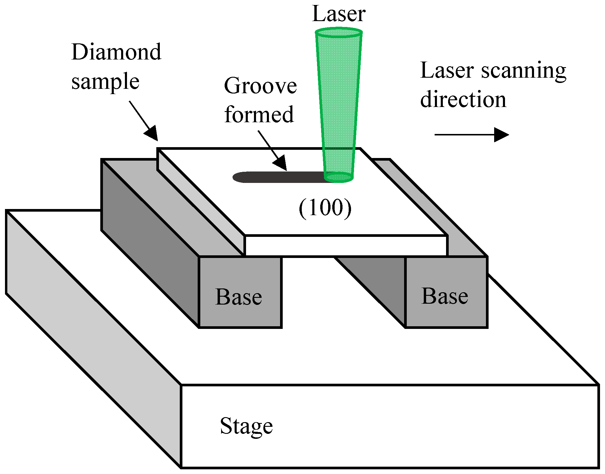
Figure 2.
SEM images of the grooves obtained by irradiating with varying laser fluences on the CVD sample (a) 7.8 J/cm2; (b) 9.1 J/cm2; (c) 9.9 J/cm2; (d) 10.3 J/cm2; (e) 11.0 J/cm2; and on the HPHT sample (f) 7.8 J/cm2; (g) 9.1 J/cm2; (h) 9.9 J/cm2; (i) 10.3 J/cm2; (j) 11.0 J/cm2.
Figure 2.
SEM images of the grooves obtained by irradiating with varying laser fluences on the CVD sample (a) 7.8 J/cm2; (b) 9.1 J/cm2; (c) 9.9 J/cm2; (d) 10.3 J/cm2; (e) 11.0 J/cm2; and on the HPHT sample (f) 7.8 J/cm2; (g) 9.1 J/cm2; (h) 9.9 J/cm2; (i) 10.3 J/cm2; (j) 11.0 J/cm2.

Figure 3.
SEM images of the bottom of the groove formed by forward irradiation of (a) the HPHT sample and (b) the CVD sample at 10.3 J/cm2.
Figure 3.
SEM images of the bottom of the groove formed by forward irradiation of (a) the HPHT sample and (b) the CVD sample at 10.3 J/cm2.

Figure 4.
SEM images of the grooves formed by the reverse irradiation of the HPHT sample at a fluence of 9.1 J/cm2 showing (a) the groove bottom; (b) at a larger magnification.
Figure 4.
SEM images of the grooves formed by the reverse irradiation of the HPHT sample at a fluence of 9.1 J/cm2 showing (a) the groove bottom; (b) at a larger magnification.
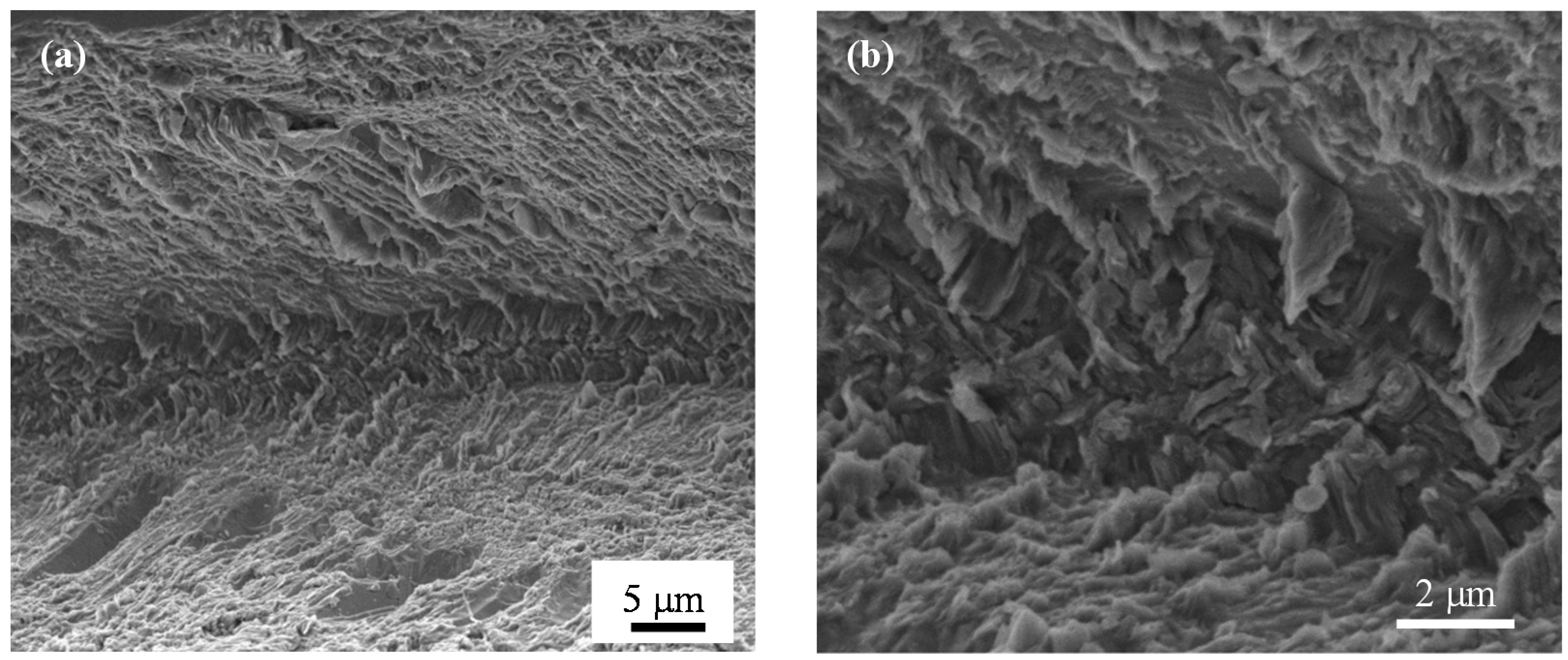
Figure 5.
Cross-sectional profiles of grooves obtained on (a) the CVD sample; (b) the upper surface and (c) the lower surface of the HPHT sample.
Figure 5.
Cross-sectional profiles of grooves obtained on (a) the CVD sample; (b) the upper surface and (c) the lower surface of the HPHT sample.

Figure 6.
SEM image of the dark cloud found around the groove on the upper surface of the HPHT sample, machined by a fluence of 10.3 J/cm2; (a) the entire cloud and (b) in detail.
Figure 6.
SEM image of the dark cloud found around the groove on the upper surface of the HPHT sample, machined by a fluence of 10.3 J/cm2; (a) the entire cloud and (b) in detail.
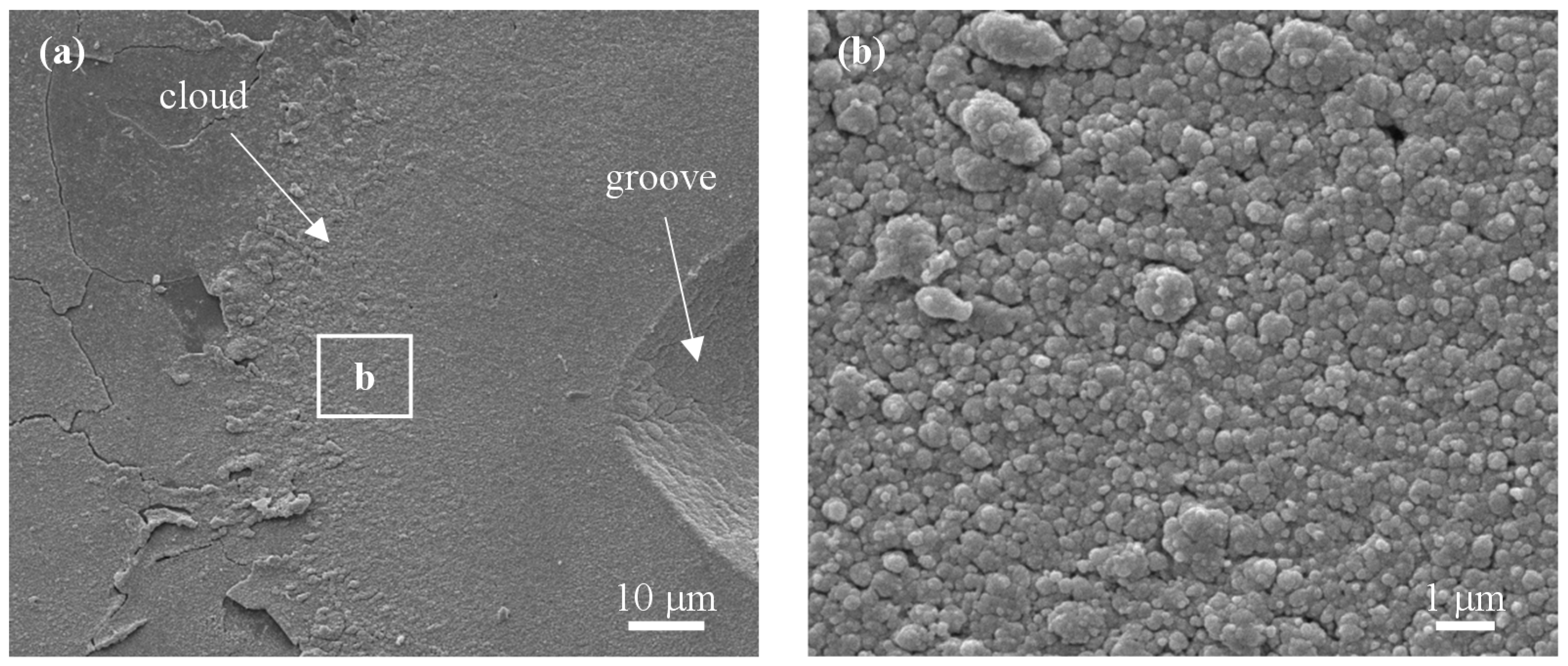
Figure 7.
Raman spectra of the point 10 μm from the edge of the groove.
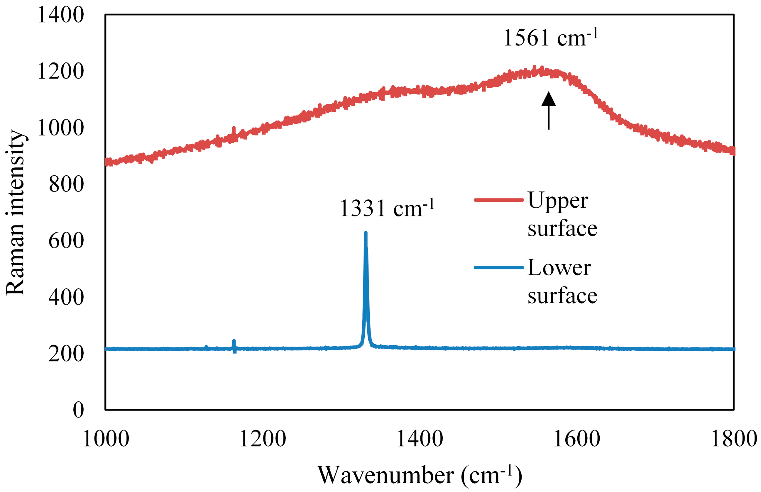
Figure 8.
Schematic of the mechanism of interference at both surfaces (light ray is shown at an angle for illustration) showing (a) laser interaction with the sample; (b) destructive interference at the upper surface and (c) constructive interference at the lower surface.
Figure 8.
Schematic of the mechanism of interference at both surfaces (light ray is shown at an angle for illustration) showing (a) laser interaction with the sample; (b) destructive interference at the upper surface and (c) constructive interference at the lower surface.

Figure 9.
Raman spectra of the unirradiated surfaces, showing crystal defects in CVD.
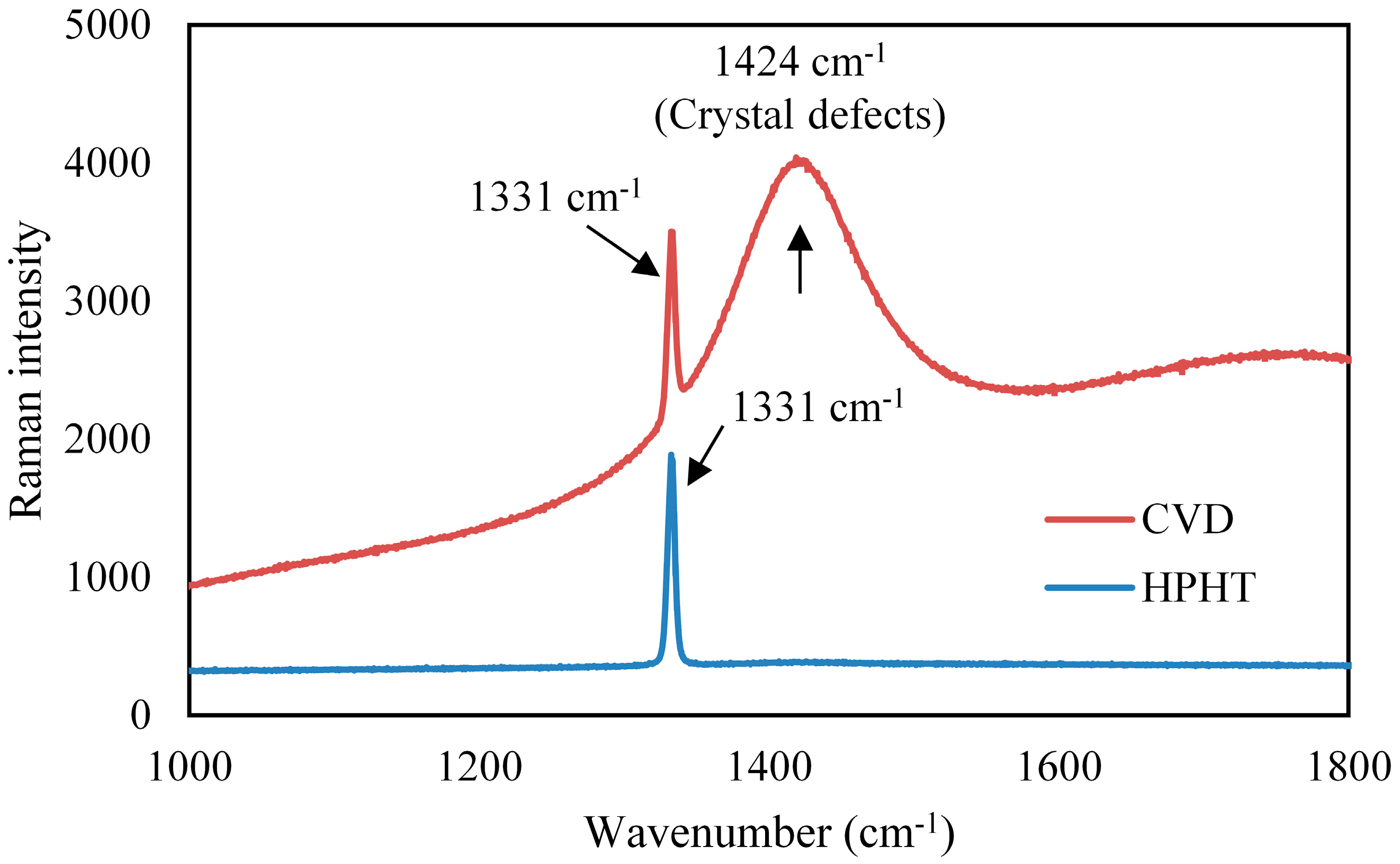
Figure 10.
SEM image of the bottom of the laser-induced groove on HPHT showing cracks propagating in a diagonal direction.
Figure 10.
SEM image of the bottom of the laser-induced groove on HPHT showing cracks propagating in a diagonal direction.

Figure 11.
Raman spectra of a point on the groove wall.


Table 1.
Experimental laser parameters.
| Parameters | Value |
|---|---|
| Wavelength (nm) | 532 |
| Pulse width (ns) | 15.6 |
| Repetition frequency (kHz) | 1 |
| Power (mW) | 450, 515, 560, 590, 625 |
| Fluence on upper surface (J/cm2) | 7.8, 9.1, 9.9, 10.3, 11.0 |
| Scanning speed (mm/s) | 1 |
© 2017 by the authors. Licensee MDPI, Basel, Switzerland. This article is an open access article distributed under the terms and conditions of the Creative Commons Attribution (CC BY) license (http://creativecommons.org/licenses/by/4.0/).
Share and Cite
MDPI and ACS Style
Takayama, N.; Yan, J. Laser Irradiation Responses of a Single-Crystal Diamond Produced by Different Crystal Growth Methods. Appl. Sci. 2017, 7, 815. https://doi.org/10.3390/app7080815
AMA Style
Takayama N, Yan J. Laser Irradiation Responses of a Single-Crystal Diamond Produced by Different Crystal Growth Methods. Applied Sciences. 2017; 7(8):815. https://doi.org/10.3390/app7080815
Chicago/Turabian StyleTakayama, Nozomi, and Jiwang Yan. 2017. "Laser Irradiation Responses of a Single-Crystal Diamond Produced by Different Crystal Growth Methods" Applied Sciences 7, no. 8: 815. https://doi.org/10.3390/app7080815
Note that from the first issue of 2016, this journal uses article numbers instead of page numbers. See further details here.