Enhancing Interpretation of Ambiguous Voice Instructions based on the Environment and the User’s Intention for Improved Human-Friendly Robot Navigation


Abstract
:1. Introduction
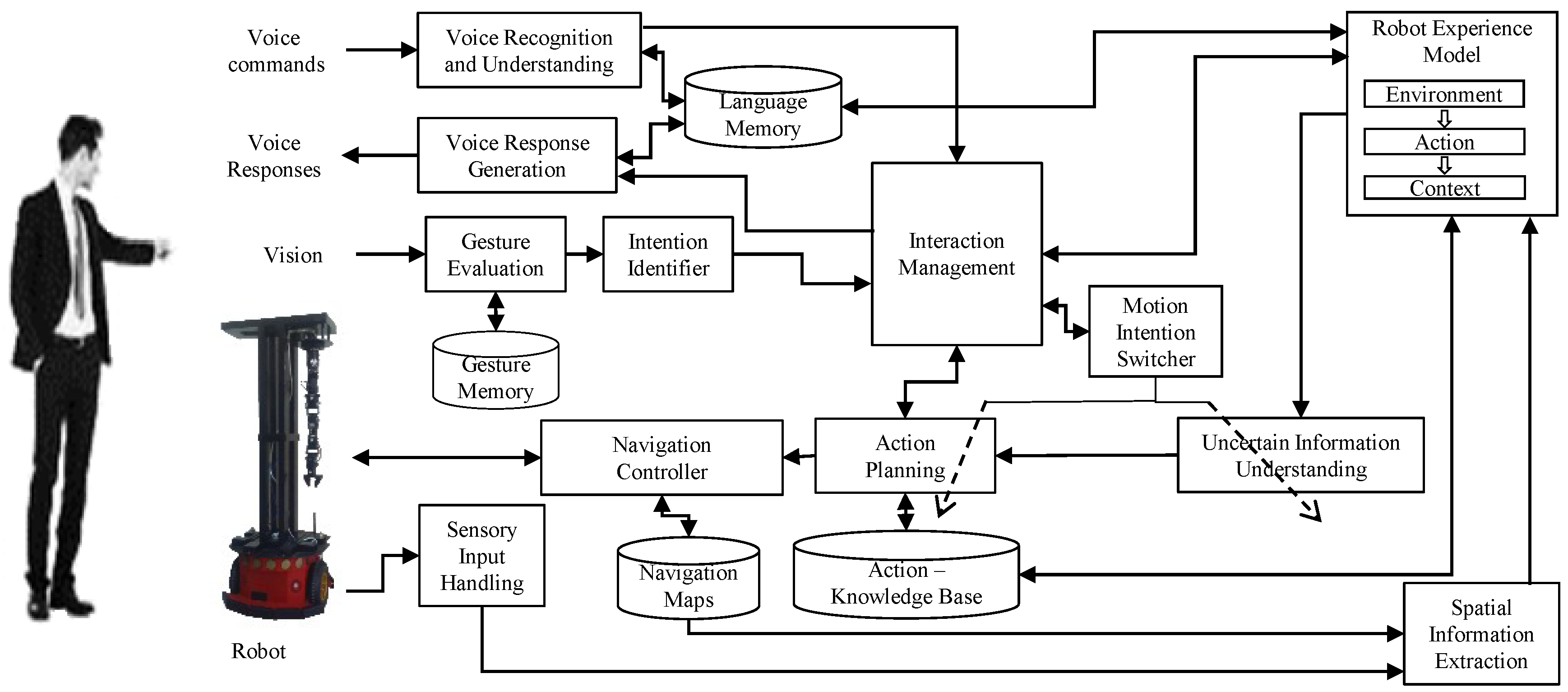
2. System Overview
3. Quantification of Uncertain Information
3.1. Structure of the User Command
<userCommand> = <action> <actionModifier> <direction>;
<action> = (go | move);
<actionModifier> = (far | medium | little);
<direction> = (forward | backward | left | right);
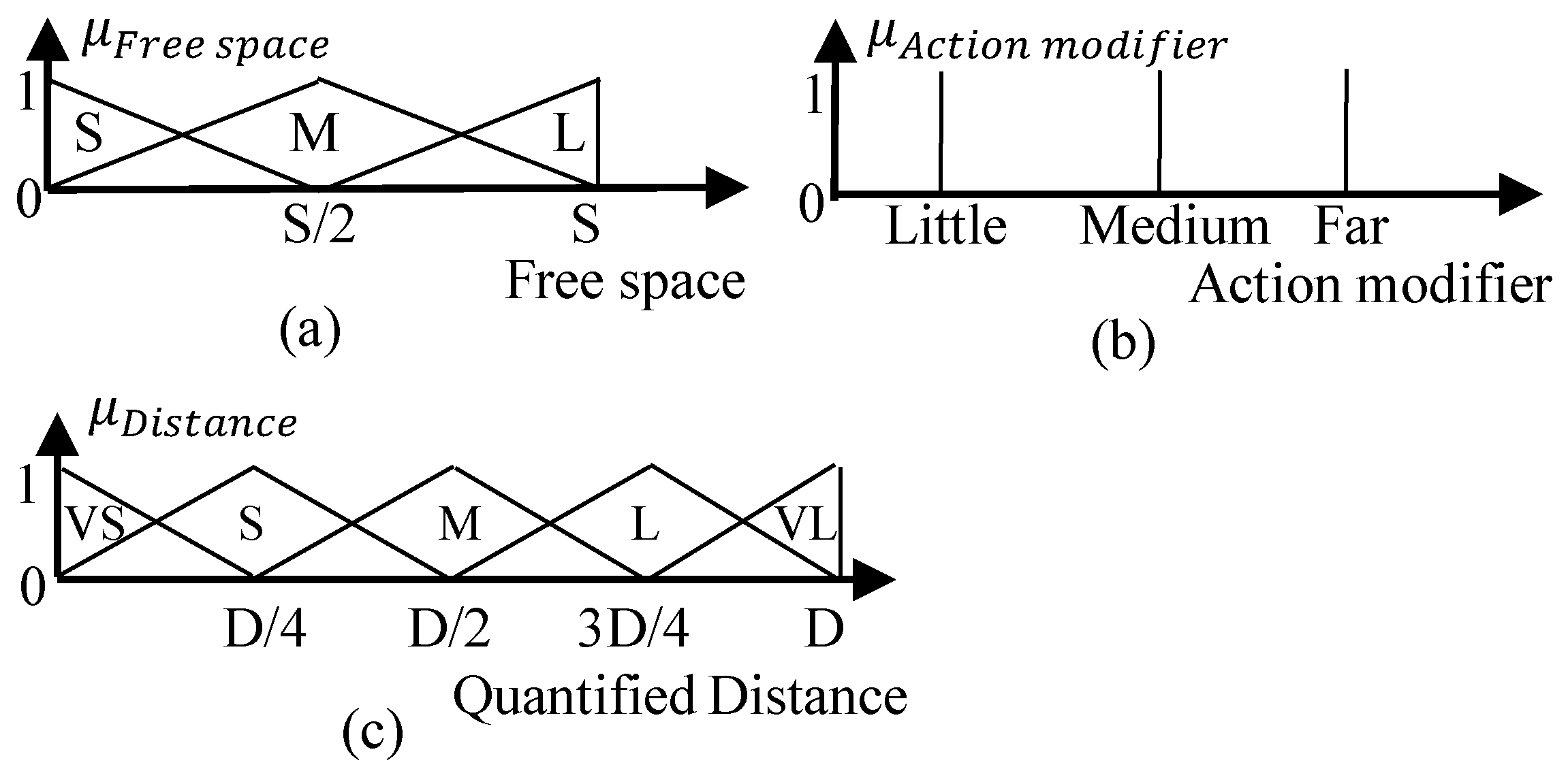
3.2. Uncertain Information Understanding Module (UIUM)
3.3. Motion Intention-Switching by Identifying the Actual Intention of the User
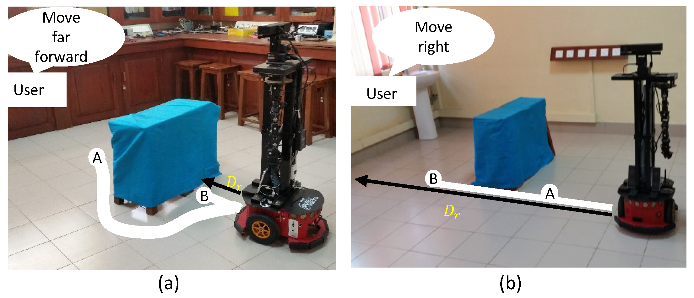
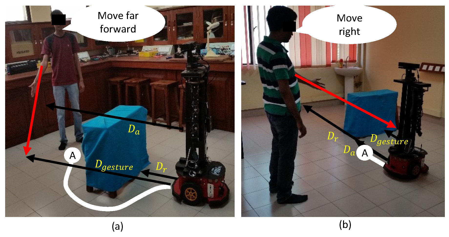
3.3.1. Rationale behind the Evaluation of Gestures Accompanied with User Instructions
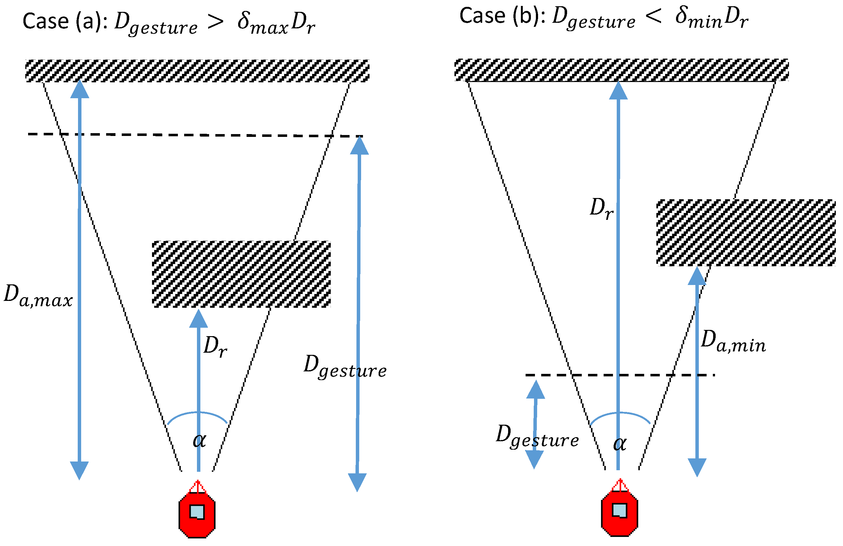
3.3.2. Pointing-Gesture Evaluation
3.3.3. Motion Intention Switcher (MIS)
| Algorithm 1:Assigning perceptive distance (D) |
| INPUT: , , |
| OUTPUT: D |
| if then |
| else if then |
| else |
| |
| end if |
3.3.4. Estimation of Alternative Perceptive Distance ()
4. Results and Discussion
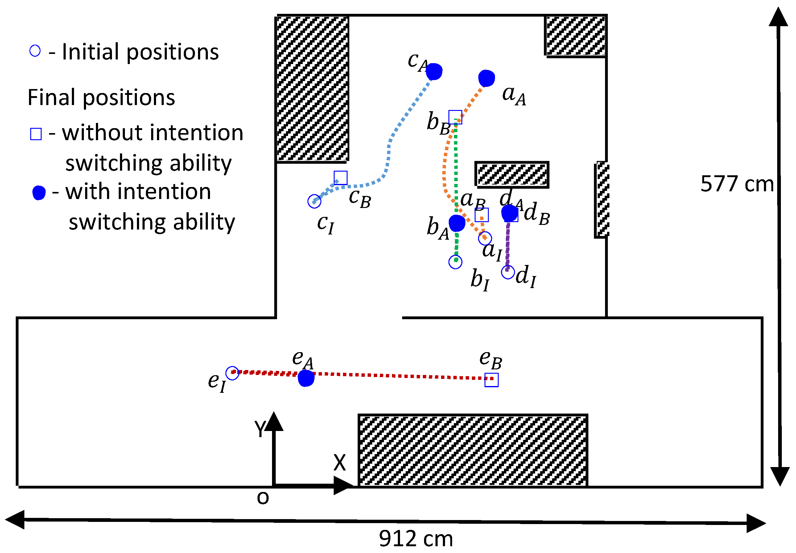
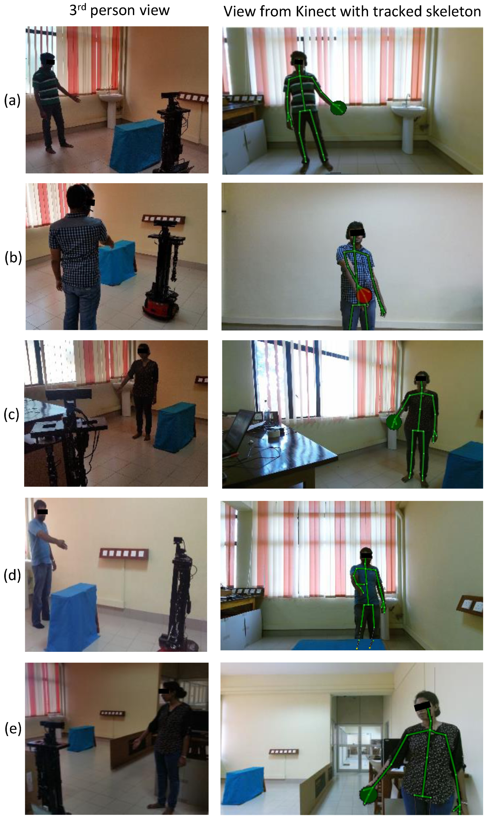
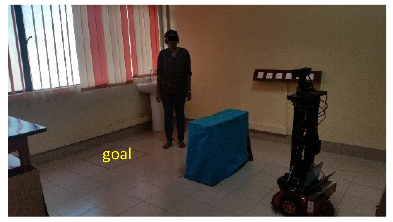
4.1. Experimental Setup
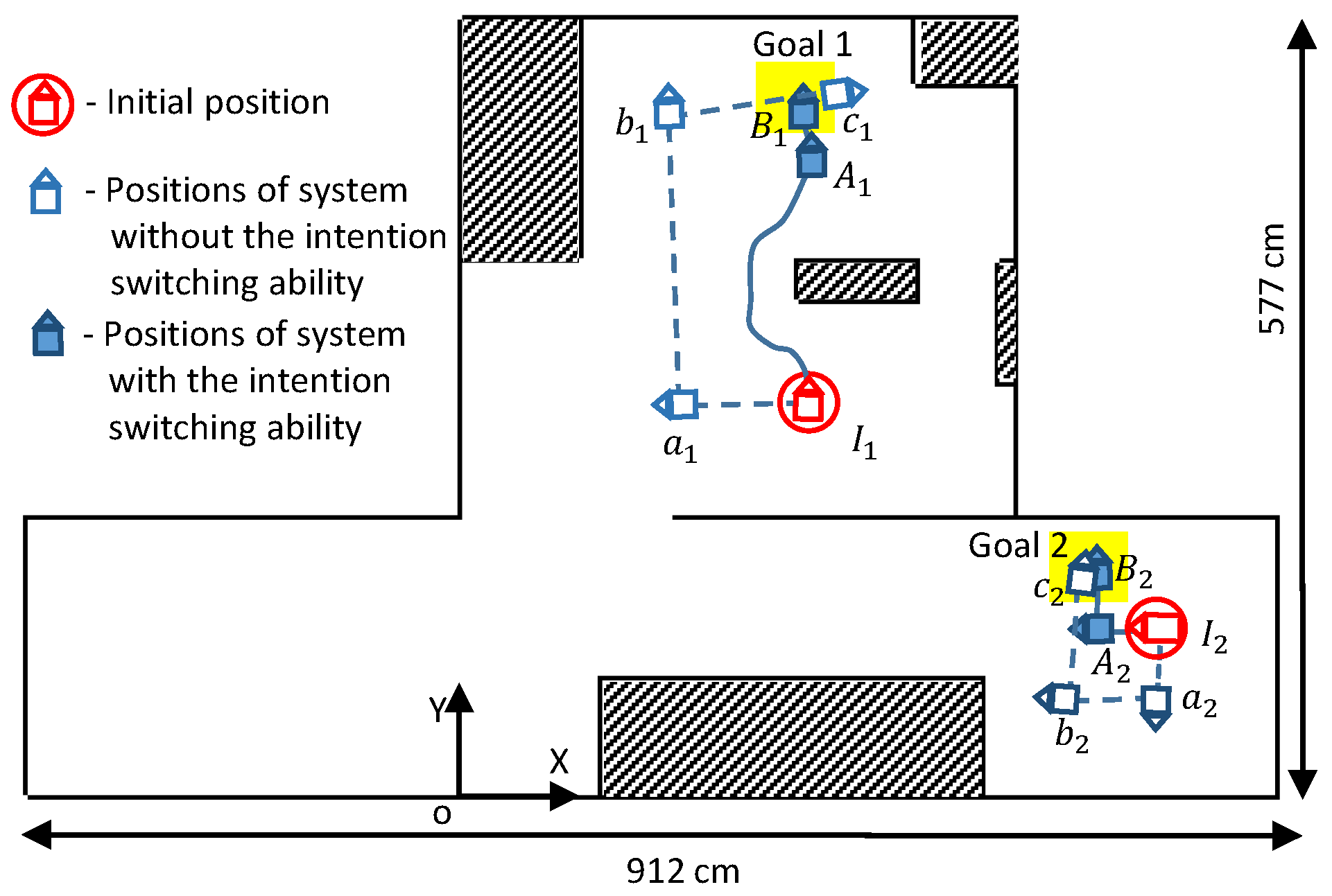
4.2. Validation of the Behavior of the Motion Intention Switcher (MIS)
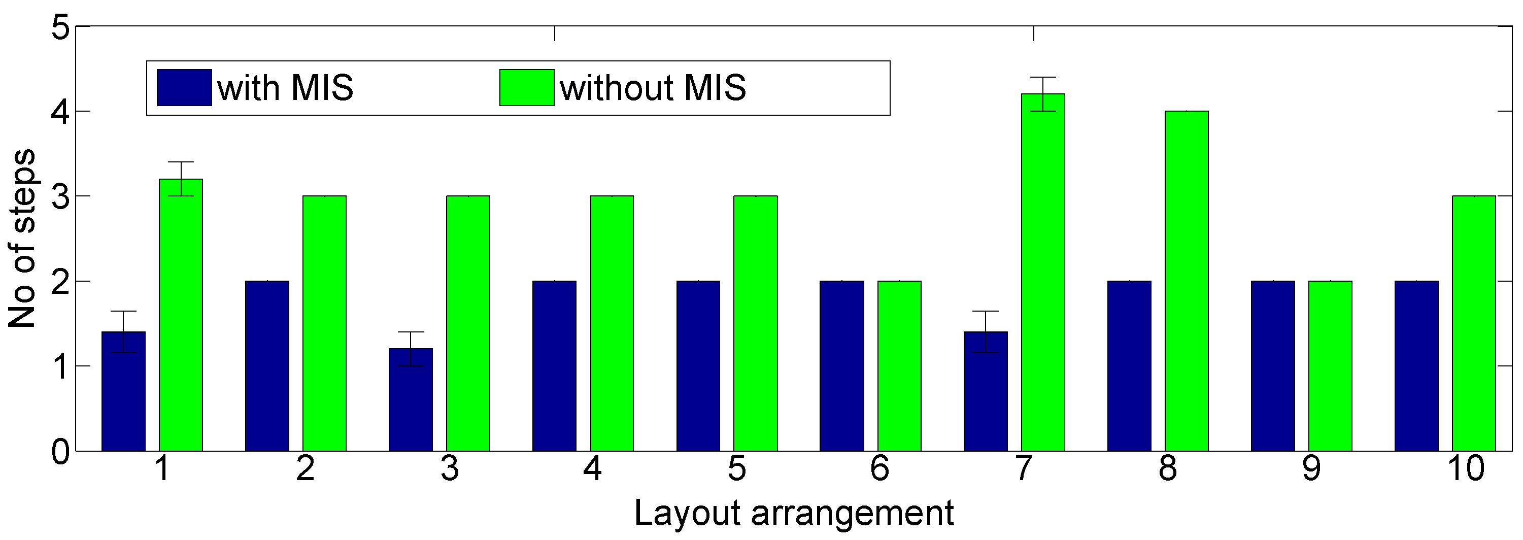
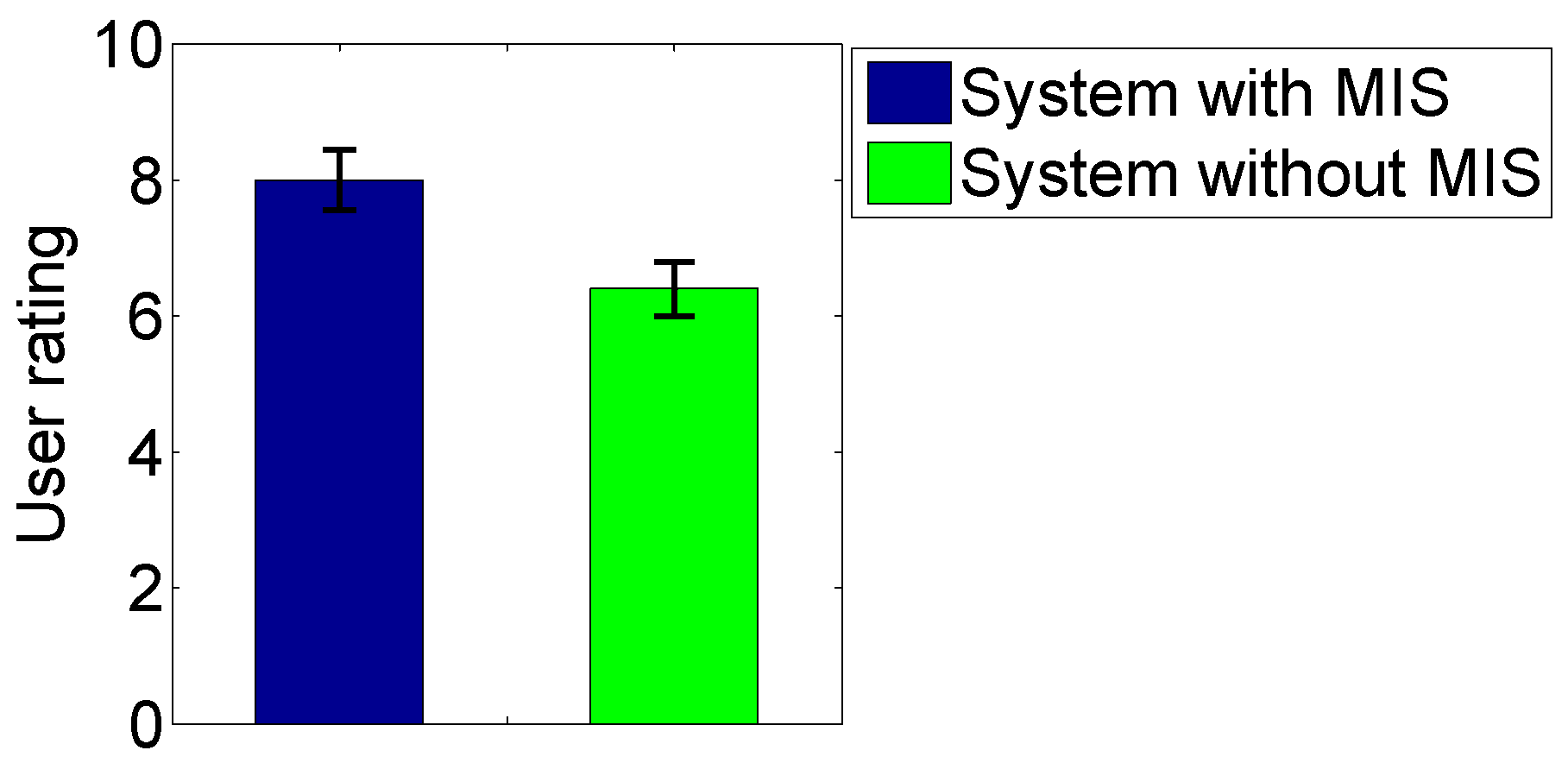
4.3. Evaluation of Performance Gain of the Proposed Method
5. Conclusions
Supplementary Materials
Acknowledgments
Author Contributions
Conflicts of Interest
References
- Arkin, R.C. Behavior-Based Robotics; MIT Press: London, UK, 1998. [Google Scholar]
- Jayawardena, C.; Kuo, I.; Broadbent, E.; MacDonald, B.A. Socially Assistive Robot HealthBot: Design, Implementation, and Field Trials. IEEE Syst. J. 2016, 10, 1056–1067. [Google Scholar] [CrossRef]
- Chu, M.T.; Khosla, R.; Khaksar, S.M.S.; Nguyen, K. Service Innovation through Social Robot Engagement to Improve Dementia Care Quality. Assist. Technol. 2016, 29, 8–18. [Google Scholar] [CrossRef] [PubMed]
- Fischinger, D.; Einramhof, P.; Papoutsakis, K.; Wohlkinger, W.; Mayer, P.; Panek, P.; Hofmann, S.; Koertner, T.; Weiss, A.; Argyros, A.; et al. Hobbit, a care robot supporting independent living at home: First prototype and lessons learned. Robot. Auton. Syst. 2016, 75, 60–78. [Google Scholar] [CrossRef]
- Johnson, D.O.; Cuijpers, R.H.; Juola, J.F.; Torta, E.; Simonov, M.; Frisiello, A.; Bazzani, M.; Yan, W.; Weber, C.; Wermter, S.; et al. Socially Assistive Robots: A comprehensive approach to extending independent living. Int. J. Soc. Robot. 2014, 6, 195–211. [Google Scholar] [CrossRef]
- Smarr, C.A.; Mitzner, T.L.; Beer, J.M.; Prakash, A.; Chen, T.L.; Kemp, C.C.; Rogers, W.A. Domestic robots for older adults: Attitudes, preferences, and potential. Int. J. Soc. Robot. 2014, 6, 229–247. [Google Scholar] [CrossRef] [PubMed]
- Kleanthous, S.; Christophorou, C.; Tsiourti, C.; Dantas, C.; Wintjens, R.; Samaras, G.; Christodoulou, E. Analysis of Elderly Users’ Preferences and Expectations on Service Robot’s Personality, Appearance and Interaction. In Proceedings of the International Conference on Human Aspects of IT for the Aged Population, Toronto, ON, Canada, 17–22 July 2016; Springer: Berlin, Germany, 2016; pp. 35–44. [Google Scholar]
- Wang, N.; Broz, F.; Di Nuovo, A.; Belpaeme, T.; Cangelosi, A. A user-centric design of service robots speech interface for the elderly. In Recent Advances in Nonlinear Speech Processing; Springer: Berlin, Germany, 2016; pp. 275–283. [Google Scholar]
- Tellex, S.; Kollar, T.; Dickerson, S.; Walter, M.R.; Banerjee, A.G.; Teller, S.; Roy, N. Understanding natural language commands for robotic navigation and mobile manipulation. In Proceedings of the Twenty-Fifth AAAI Conference on Artificial Intelligence, San Francisco, CA, USA, 7–11 August 2011; AAAI Press: Palo Alto, CA, USA, 2011; pp. 1507–1514. [Google Scholar]
- Hemachandra, S.; Duvallet, F.; Howard, T.M.; Roy, N.; Stentz, A.; Walter, M.R. Learning models for following natural language directions in unknown environments. In Proceedings of the 2015 IEEE International Conference on Robotics and Automation (ICRA), Seattle, WA, USA, 26–30 May 2015; IEEE: Piscataway, NJ, USA, 2015; pp. 5608–5615. [Google Scholar]
- Skubic, M.; Perzanowski, D.; Blisard, S.; Schultz, A.; Adams, W.; Bugajska, M.; Brock, D. Spatial language for human-robot dialogs. IEEE Trans. Syst. Man Cybern. C (Appl. Rev.) 2004, 34, 154–167. [Google Scholar] [CrossRef]
- Kawamura, K.; Bagchi, S.; Park, T. An intelligent robotic aid system for human services. In NASA Conference Publication; NASA: Washington, DC, USA, 1994; pp. 413–420. [Google Scholar]
- Pulasinghe, K.; Watanabe, K.; Izumi, K.; Kiguchi, K. Modular fuzzy-neuro controller driven by spoken language commands. IEEE Trans. Syst. Man Cybern. B 2004, 34, 293–302. [Google Scholar] [CrossRef]
- Jayawardena, C.; Watanabe, K.; Izumi, K. Controlling a robot manipulator with fuzzy voice commands using a probabilistic neural network. Neural Comput. Appl. 2007, 16, 155–166. [Google Scholar] [CrossRef]
- Jayasekara, A.G.B.P.; Watanabe, K.; Kiguchi, K.; Izumi, K. Interpreting Fuzzy Linguistic Information by Acquiring Robot’s Experience Based on Internal Rehearsal. J. Syst. Des. Dyn. 2010, 4, 297–313. [Google Scholar] [CrossRef]
- Lin, C.T.; Kan, M.C. Adaptive fuzzy command acquisition with reinforcement learning. IEEE Trans. Fuzzy Syst. 1998, 6, 102–121. [Google Scholar]
- Jayasekara, A.G.B.P.; Watanabe, K.; Kiguchi, K.; Izumi, K. Interpretation of fuzzy voice commands for robots based on vocal cues guided by user’s willingness. In Proceedings of the 2010 IEEE/RSJ International Conference on Intelligent Robots and Systems, Taipei, Taiwan, 18–22 October 2010; pp. 778–783. [Google Scholar]
- Jayasekara, A.G.B.P.; Watanabe, K.; Izumi, K. Understanding user commands by evaluating fuzzy linguistic information based on visual attention. Artif. Life Robot. 2009, 14, 48–52. [Google Scholar] [CrossRef]
- Schiffer, S.; Ferrein, A.; Lakemeyer, G. Reasoning with qualitative positional information for domestic domains in the situation calculus. J. Intell. Robot. Syst. 2012, 66, 273–300. [Google Scholar] [CrossRef]
- Muthugala, M.A.V.J.; Jayasekara, A.G.B.P. Interpretation of Uncertain Information in Mobile Service Robots by Analyzing Surrounding Spatial Arrangement Based on Occupied Density Variation. In Proceedings of the 2016 IEEE/RSJ International Conference on Intelligent Robots and Systems (IROS), Daejeon, Korea, 9–14 October 2016; pp. 1517–1523. [Google Scholar]
- Matuszek, C.; Bo, L.; Zettlemoyer, L.; Fox, D. Learning from Unscripted Deictic Gesture and Language for Human-Robot Interactions. In Proceedings of the Twenty-Eighth AAAI Conference on Artificial Intelligence (AAAI), Québec City, QC, Canada, 27–31 July 2014; pp. 2556–2563. [Google Scholar]
- Whitney, D.; Eldon, M.; Oberlin, J.; Tellex, S. Interpreting multimodal referring expressions in real time. In Proceedings of the 2016 IEEE Intenational Conferece on Robotics and Automation (ICRA), Stockholm, Sweden, 16–21 May 2016; pp. 3331–3338. [Google Scholar]
- Muthugala, M.A.V.J.; Jayasekara, A.G.B.P. MIRob: An intelligent service robot that learns from interactive discussions while handling uncertain information in user instructions. In Proceedings of the 2016 Moratuwa Engineering Research Conference (MERCon), Moratuwa, Sri Lanka, 5–6 April 2016; pp. 397–402. [Google Scholar]
- Mavridis, N. A review of verbal and non-verbal human–robot interactive communication. Robot. Auton. Syst. 2015, 63, 22–35. [Google Scholar] [CrossRef]
- Bethel, C.L.; Murphy, R.R. Review of human studies methods in HRI and recommendations. Int. J. Soc. Robot. 2010, 2, 347–359. [Google Scholar] [CrossRef]
- Jayasekara, A.B.P.; Watanabe, K.; Habib, M.K.; Izumi, K. Visual evaluation and fuzzy voice commands for controlling a robot manipulator. Int. J. Mech. Manuf. Syst. 2010, 3, 244–260. [Google Scholar] [CrossRef]
- Lee, M.K.; Forlizzi, J.; Kiesler, S.; Rybski, P.; Antanitis, J.; Savetsila, S. Personalization in HRI: A longitudinal field experiment. In Proceedings of the 2012 7th ACM/IEEE International Conference on Human-Robot Interaction (HRI), Boston, MA, USA, 5–8 March 2012; pp. 319–326. [Google Scholar]


| Input Memberships | Free Space | |||
|---|---|---|---|---|
| S | M | L | ||
| Little | VS | S | M | |
| Action modifier | Medium | S | M | L |
| Far | M | L | VL | |
| User Command | Initial Position 1 | Uncertain Term | Room Size (m2) | Free Space (m2) | Without MIS | With MIS | |||||||||||||||
|---|---|---|---|---|---|---|---|---|---|---|---|---|---|---|---|---|---|---|---|---|---|
| (cm) | (cm) | Output (cm) | Final Position1 | (cm) | (cm) | (cm) | Output (cm) | Final Position1 | |||||||||||||
| a | move far forward | 254 | 302 | 88 | far | 15.08 | 12.77 | 33 | 33 | 29 | 252 | 329 | 95 | 33 | 121 | 252 | 199 | 254 | 500 | 90 | |
| b | move medium right | 220 | 272 | 179 | medium | 15.08 | 12.77 | 272 | 272 | 181 | 218 | 452 | 87 | 274 | 57 | 72 | 48 | 217 | 319 | 93 | |
| c | move far forward | 46 | 344 | 49 | far | 15.08 | 12.77 | 64 | 64 | 42 | 78 | 375 | 50 | 66 | 180 | 269 | 218 | 189 | 509 | 49 | |
| d | move far forward | 285 | 260 | 87 | far | 15.08 | 12.77 | 86 | 86 | 70 | 289 | 330 | 87 | 85 | −140 | 85 | 70 | 283 | 334 | 88 | |
| e | move medium forward | −53 | 135 | −5 | medium | 18.55 | 16.33 | 470 | 470 | 313 | 262 | 125 | −3 | 470 | 100 | 130 | 86 | 33 | 127 | −5 | |
| User Command | Uncertain Term | Room Size (m2) | Free Space (m2) | (cm) | (cm) | Intention Switched | D (cm) | Distance Moved (cm) | Position 1 (X, Y, ) | |
|---|---|---|---|---|---|---|---|---|---|---|
| Case 1 | Initial position 1 | (247, 283, 89) | ||||||||
| with MIS | A. move medium forward | medium | 15.08 | 12.77 | 57 | 128 | True | 275 | 183 | (250, 466, 89) |
| B. move little forward | little | 15.08 | 12.77 | 87 | Not detected | False | 87 | 36 | (249, 502, 89) | |
| without MIS | a. move little left | little | 15.08 | 12.77 | 206 | - | - | 206 | 86 | (160, 283, −179) |
| b. move far right | far | 15.08 | 12.77 | 270 | - | - | 270 | 219 | (149, 502, 92) | |
| c. move medium right | medium | 15.08 | 12.77 | 149 | - | - | 179 | 117 | (270, 519, 8) | |
| Case 2 | Initial position 1 | (504, 117, 179) | ||||||||
| with MIS | A. move little forward | little | 18.55 | 16.33 | 470 | 60 | True | 102 | 42 | (462, 118, 179) |
| B. move medium right | medium | 18.55 | 16.33 | 63 | Not detected | False | 63 | 42 | (460, 159, 87) | |
| without MIS | a. move medium left | medium | 18.55 | 16.33 | 98 | - | - | 98 | 64 | (504, 57, −89) |
| b. move medium right | medium | 18.55 | 16.33 | 106 | - | - | 106 | 71 | (434, 68, 175) | |
| c. move far right | far | 18.55 | 16.33 | 110 | - | - | 110 | 89 | (447, 152, 83) |
© 2017 by the authors. Licensee MDPI, Basel, Switzerland. This article is an open access article distributed under the terms and conditions of the Creative Commons Attribution (CC BY) license (http://creativecommons.org/licenses/by/4.0/).
Share and Cite
Muthugala, M.A.V.J.; Srimal, P.H.D.A.S.; Jayasekara, A.G.B.P. Enhancing Interpretation of Ambiguous Voice Instructions based on the Environment and the User’s Intention for Improved Human-Friendly Robot Navigation. Appl. Sci. 2017, 7, 821. https://doi.org/10.3390/app7080821
Muthugala MAVJ, Srimal PHDAS, Jayasekara AGBP. Enhancing Interpretation of Ambiguous Voice Instructions based on the Environment and the User’s Intention for Improved Human-Friendly Robot Navigation. Applied Sciences. 2017; 7(8):821. https://doi.org/10.3390/app7080821
Chicago/Turabian StyleMuthugala, M. A. Viraj J., P. H. D. Arjuna S. Srimal, and A. G. Buddhika P. Jayasekara. 2017. "Enhancing Interpretation of Ambiguous Voice Instructions based on the Environment and the User’s Intention for Improved Human-Friendly Robot Navigation" Applied Sciences 7, no. 8: 821. https://doi.org/10.3390/app7080821