Design of 1-Bit Digital Reconfigurable Reflective Metasurface for Beam-Scanning


Key Laboratory of High Speed Circuit Design and EMC of Ministry of Education, School of Electronic Engineering, Collaborative Innovation Center of Information Sensing and Understanding, Xidian University, Xi’an 710071, China
*
Authors to whom correspondence should be addressed.
Appl. Sci. 2017, 7(9), 882; https://doi.org/10.3390/app7090882
Submission received: 1 August 2017
/
Revised: 24 August 2017
/
Accepted: 25 August 2017
/
Published: 28 August 2017
(This article belongs to the Special Issue Metasurfaces: Physics and Applications)
Abstract
:A 1-bit digital reconfigurable reflective metasurface (RRM) with 20 × 20 cells is presented, fabricated and measured for beam-scanning performance in this paper. The cell is designed with a single layer structure and one varactor diode, controlled electronically. The cell’s phase compensation is over 180° between 3 GHz and 4 GHz and the two states with 180° phase difference are selected as coding “0” and coding “1”. By the fuzzy quantification theory, all the elements on the RRM are set to be coding “0” or coding “1” according to the phase compensation calculated by MATLAB. Furthermore, by changing the coding of the RRM, it can achieve beam-scanning. The simulation results show that the beam-scanning range is over ±60°. The RRM prototype is fabricated and experimentally tested for principle. The gain of the RRM is 18 dB and the 3 dB bandwidth is about 16.6%. The 1-bit digital RRM is preferred in practical implementations due to less error and much easier bias voltage control. The proposed RRM successfully balances the performance and system complexity, especially in the large-scale antenna designs. The experimental and simulated results are in good agreement to prove the correctness and feasibility of the design of the 1-bit digital RRM.
1. Introduction
Due to its hybrid phased array and parabolic reflector array, reconfigurable reflective metasurface (RRM) has attracted a great deal of attention and interest recently [1]. With electronic switches, PIN diodes, metamaterials and so on, RRM can produce versatile performances, for instance, lightweight, low profile, less system complexity, high efficiency and flexible radiation characteristics [2,3]. Consequently, RRM have been proved to be an up-and-coming alternative to traditional antenna in satellite communications, long distance transmissions, imaging and in other realms [4].
In some research, PIN diode is adopted to design a metasurface element [3,5,6]. Since the PIN diode only works at one frequency at two states, ON and OFF, the bandwidth of the reconfigurable reflective metasurface is very narrow. If we want to change the operating frequency to get a wide bandwidth, the range of the cell’s phase compensation maybe not adequate. When the frequency changes, the element may not be appropriate to design the reflective metasurface [7,8]. However, the element with varactor diode can work at different frequencies by controlling the bias voltage across the varactor. As a result, it has more potential applications since it can work in a wider bandwidth [9,10,11]. These electronically-controlled digital reflective metasurfaces have been proposed for different practical applications such as tunable absorbers, reconfigurable antennas, EM wave modulators, tunable chiral metamaterials, reprogrammable hologram, and so on [12,13].
In this paper, a 1-bit digital RRM is designed, fabricated, and experimentally demonstrated to achieve beam-scanning. The 1-bit digital reconfigurable reflective metasurface unit’s phase compensation is over 180° between 3 GHz and 4 GHz and the two states with 180° phase difference are selected as coding “0” and coding “1”. In addition, a 1-bit digital RRM composed of 20 × 20 units is presented. Due to the theory of fuzzy quantification, every element on the RRM is set to be coding “0” or coding “1” to replace the desired phase compensation [14,15]. The RRM realizes the beam-scanning performance by controlling the coding and the scanning angle can reach ±60°. Finally, the antenna has been manufactured and measured to ensure that the design is credible and feasible. The results of this research provide new perspectives on the use of the digital reprogrammable reconfigurable reflective metasurface.
2. Materials and Methods
2.1. Description of the 1-Bit Digital Element and RRM
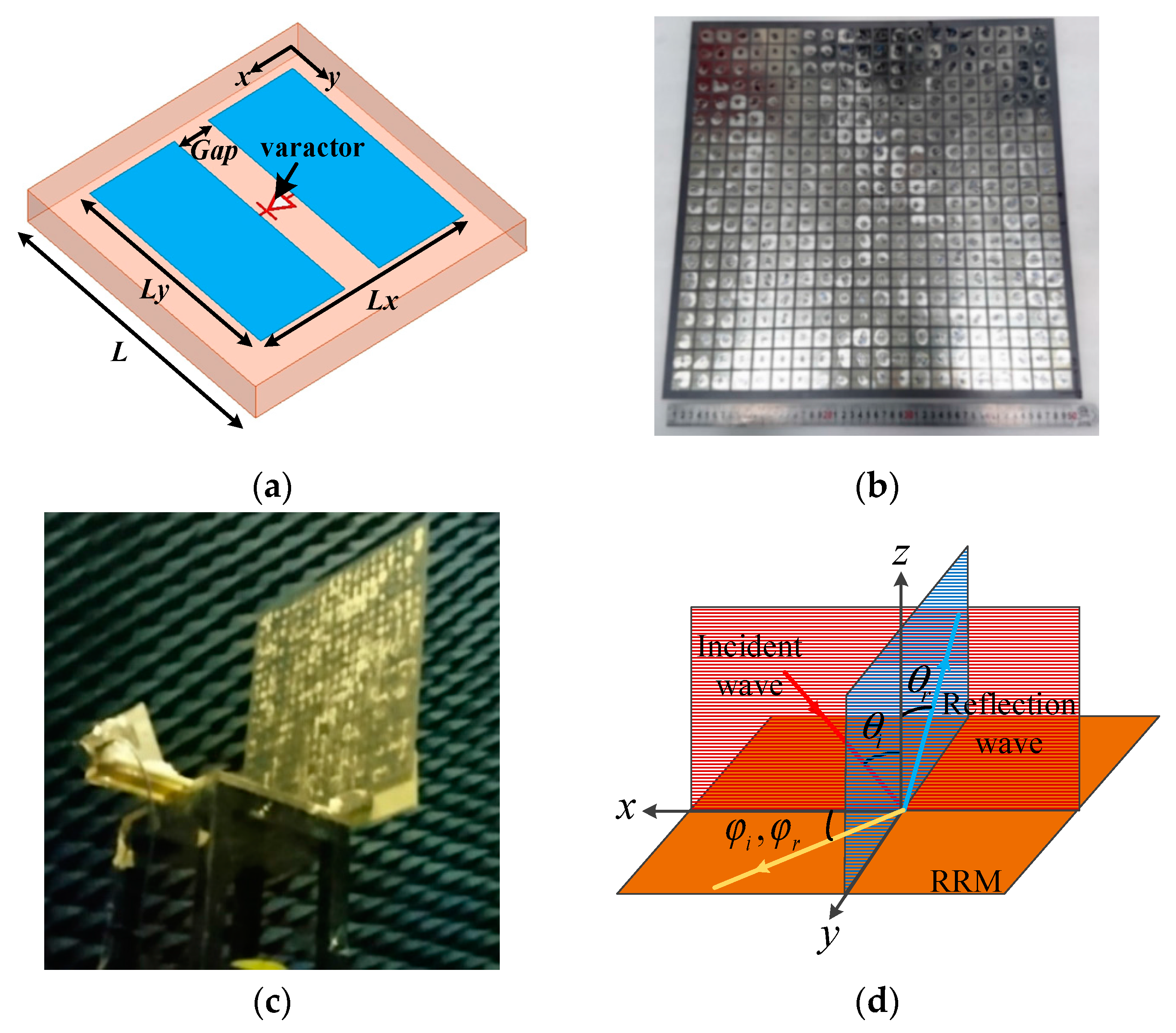
In this study, the 1-bit digital reconfigurable reflective metasurface element is designed to obtain the digital phase compensation to replace the accurate phase compensation. As shown in Figure 1a, the 1-bit digital reconfigurable reflective metasurface element adopts a single layer patch structure with a varactor diode through the gap between the two patches. The unit is etched on a dielectric substrate and the bottom is the metal ground. The dielectric constant of the dielectric substrate is 2.65 and the thickness is 3 mm.
The remaining structure parameters of the 1-bit digital element are provided in Table 1. The proposed element is simulated with the infinite periodic boundary condition in HFSS 15.0 [16]. By controlling the bias voltage across varactor diode, the phase compensation of the element can be adjusted as desired. A 1-bit 20 × 20 RRM is present and fabricated at 3.5 GHz fed by a horn antenna using the above element, as shown in Figure 1b,c. The size of the RRM is 500 mm × 500 mm. Figure 1d gives the diagram of incident wave, reflected wave, incident angle and reflection angle in the study. The incident wave is in the xoz plane, and the reflection wave is in the yoz plane.
2.2. The Theory of Reflective Metasurface
An RRM, which consists of m × n elements, is illuminated by a feed source locating at the position vector . The reradiated electric field from the RRM in an arbitrary direction can be calculated by [2]
where is the vector of the main beam direction. is the function of the radiation pattern of the feed, and is the function of the radiation pattern of the array element. is the position vector of each element, and is the phase compensation of each cell. The phase compensation of each RRM element for a desired direction can be computed by
When the phase compensations of all units can meet (1) and (2), the RRM can radiate in the required direction. The direction of the incidence wave is and the direction of the reflection wave is , where can vary from −60° to +60°.
2.3. The Theory of Fuzzy Quantification
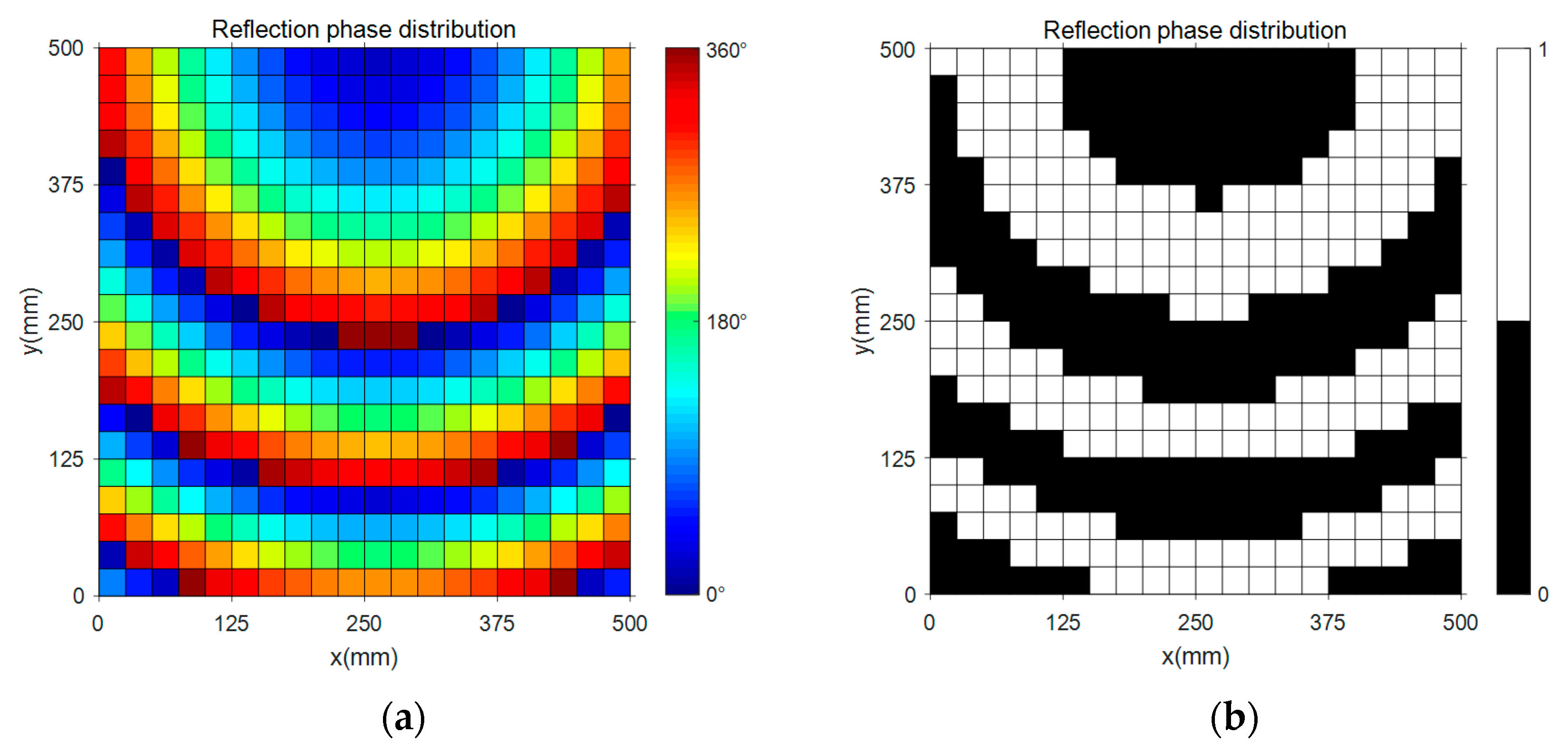
Depending on the fuzzy quantification theory, the elements on the RRM are divided into two groups, coding “0” and coding “1”. In order to get the two states of the 1-bit digital element, we need to quantify the phase compensation. The quantization standard is that if we want to get the K-bit quantization, the number of the phase states is for 360°. That is to say, is 1 for a 1-bit digital element and the phase compensation of the unit only needs to be over 180°.
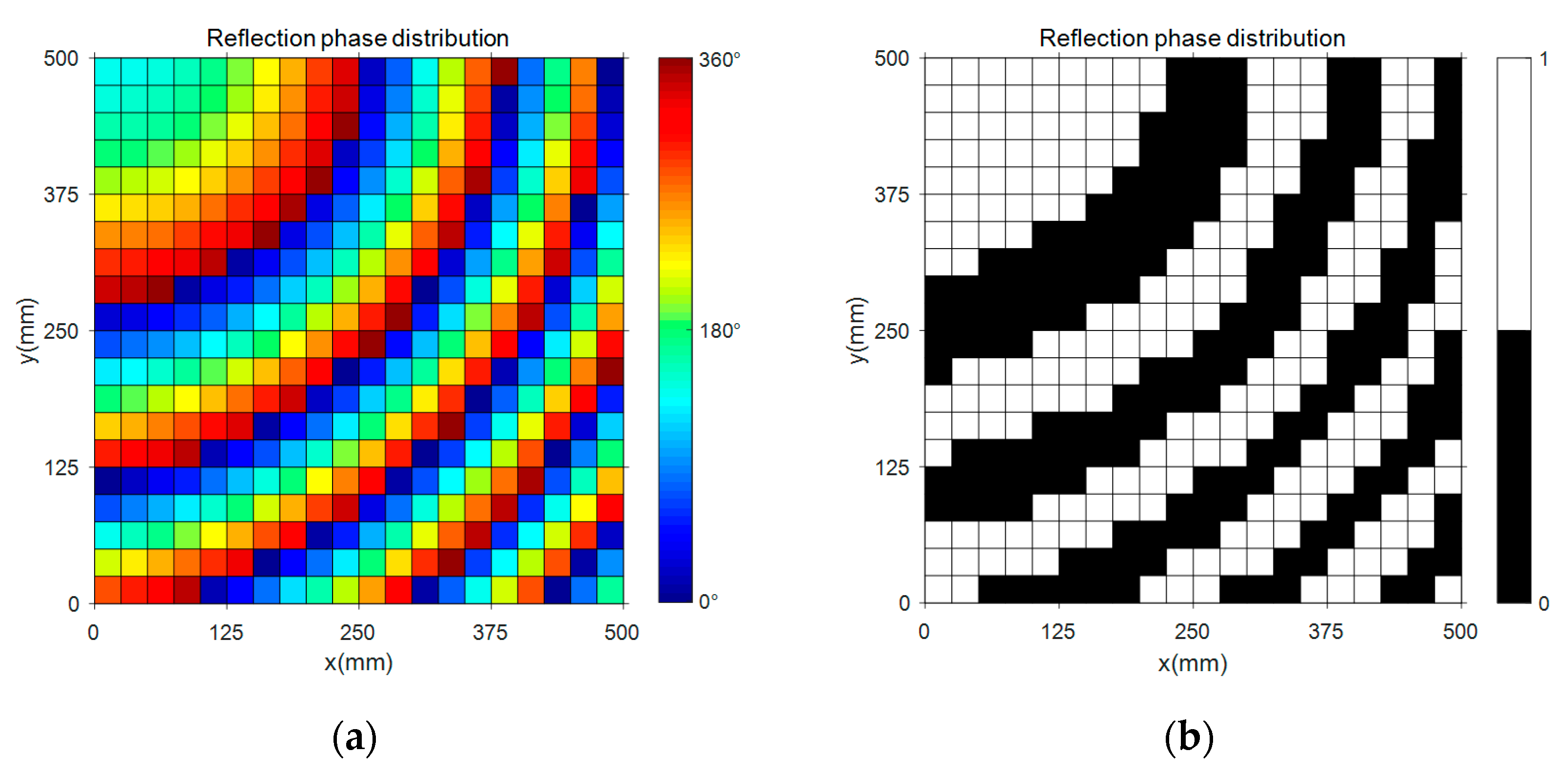
When , and , the actual and the digital phase compensation of the 1-bit digital RRM computed by MATLAB 2017a are illustrated in Figure 2, Figure 3 and Figure 4, respectively. The black blocks are coding “0” and the white blocks are coding “1”. Based on the above results, the models of the RRM are determined and simulated by using HFSS 15.0.
3. Results and Discussion
3.1. Simulation Results of the 1-Bit Digital RRM Element
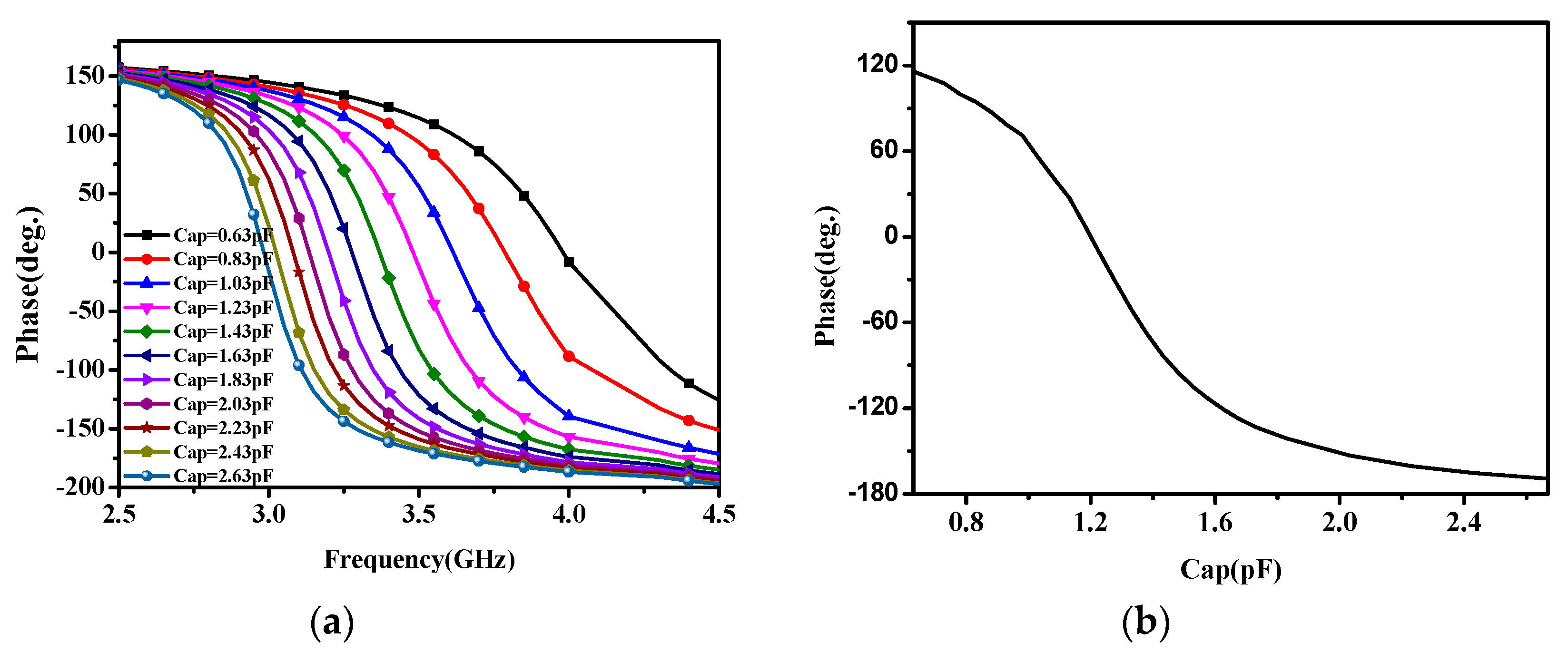
When the working frequency changes, the 180° phase compensation can be acquired by controlling the capacitance in broadband as given in Figure 5. The varactor diode can alter the phase compensations of all the RRM elements by controlling the bias voltage across the varactor diode. By tuning the capacitance value, the phase compensation curves are plotted in Figure 5a. It can be clearly observed that when the capacitance varies, the range of the phase compensation of the 1-bit digital element is more than 180°. We can see that the element can work between 3 GHz and 4 GHz with over 180° phase compensation. With this characteristic, the RRM can work in a wide bandwidth of 3 GHz to 4 GHz. Therefore, the varactor diode has more potential applications than the PIN diode in the RRM design.
Finally, we select 3.5 GHz as the operating frequency to design the RRM. Based on the simulation result in Figure 5b, the phase compensation is −145° when and the phase compensation is 35° when . We select −145° as the coding “0” and 35° as the coding “1”. Of course, we can also choose an operating frequency between 3 GHz and 4 GHz to design the 1-bit element by changing the capacitance value.
Depending on the fuzzy quantification theory, these elements are divided into two groups, corresponding to 35° and −145°. If the phase compensation of the unit is in the range 125~305°, the element is coding “1”, and the rest is coding “0”. The concept of a digital system means that we transform the phase compensation of a cell into coding “0” and coding “1” of 1-bit. By such a transformation, the RRM generates a digital concept. The digital RRM can realize the beam-scanning performance by changing the coding arrangement. In order to reduce the difficulty of design and processing, we choose the fixed capacitors of and to replace the varactor diodes. Because the phase compensations of elements are not calculated by the formulas of reflectarray, this kind of digital phase compensations are not the precise phase compensations. As a result, the gain of the RRM will be less than the current state of the art. In contarst, the digital RRM improves the bandwidth performance.
3.2. Simulation and Experimental Results of the RRM
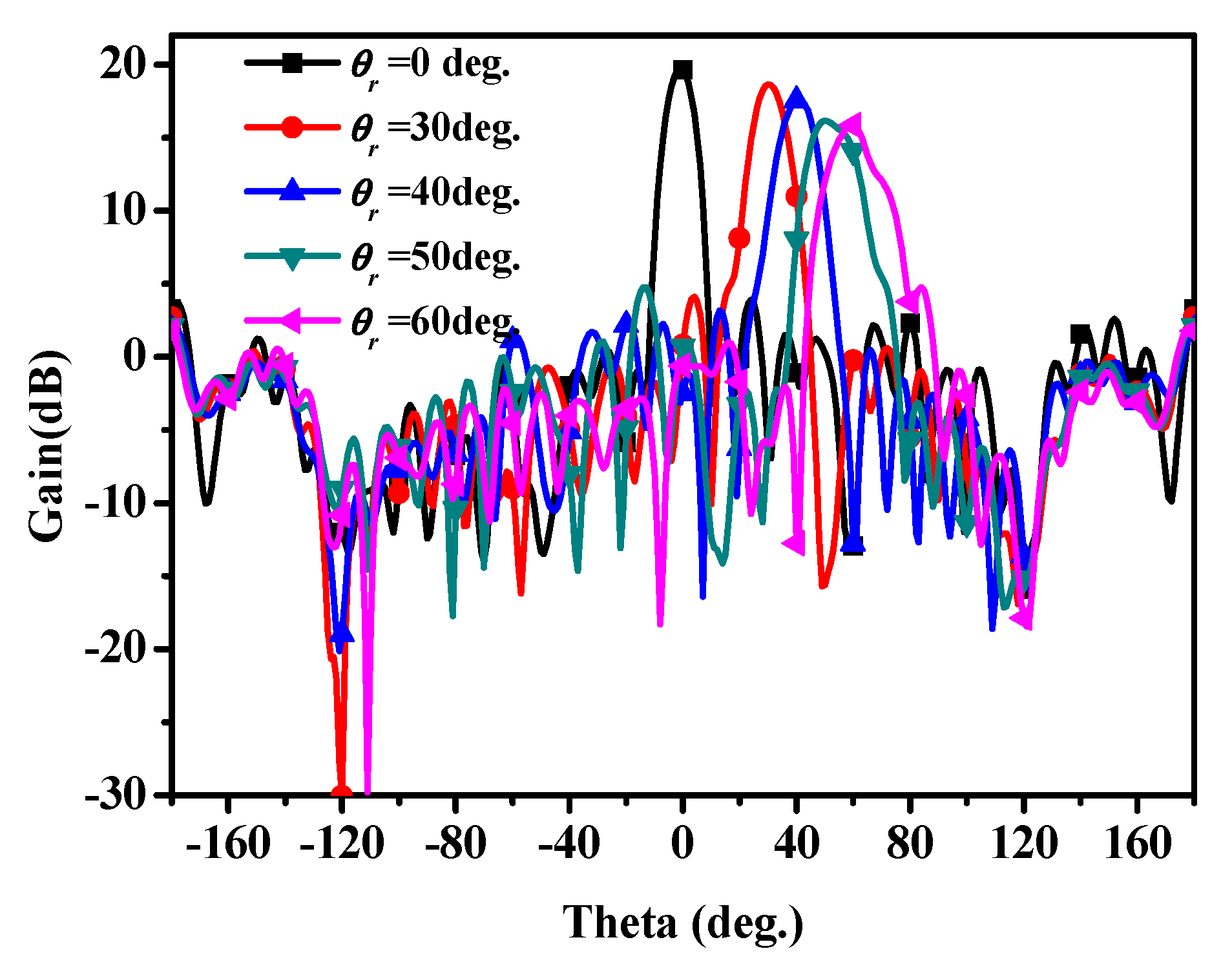
Figure 6 shows the radiation pattern of the 1-bit digital RRM when the main beam direction is 0°, 30° and 60°, respectively. From the simulation results, the characteristics of beam-scanning have been verified. For the sake of comparing the radiation characteristics in different reflection angles, the far-field performances are given in Table 2. From Table 2, we can see that when the scanning angle increases, the gain of the RRM decreases slightly. It can be seen that the 1-bit digital RRM can radiate in the same reflection angle, as assumed. The far-field radiation patterns are plotted in Figure 7 with different scanning angles and the gain of the RRM decreases slightly with the increase of the reflection angle. Then, by adjusting the coding of the 1-bit digital RRM, it can scan from −60° to +60°. These simulation results verify the validity and practicability of the 1-bit RRM.
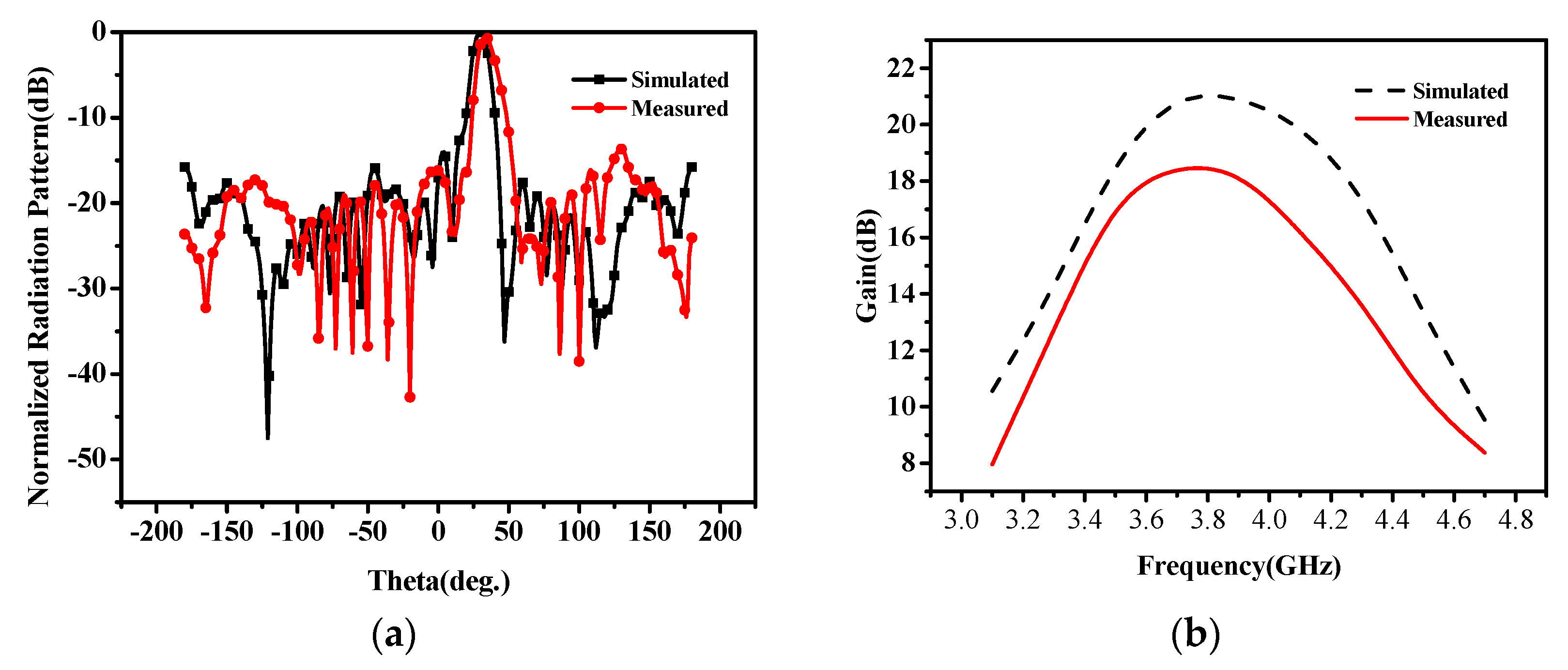
We test the performances of the proposed 1-bit digital RRM while and by using fixed capacitors. The simulated and measured results are given in Figure 8. From the simulation results, the 1-bit digital RRM can work from 3.47 GHz to 4.23 GHz, and the relative bandwidth is about 22%. The actual 3 dB bandwidth is 16.6%. The measured gain is slightly decreased. The deviation between the simulation and the measurement results may be caused by the fabrication error and capacitance error. The varactor diode is connected between the two patches by solder, which may lead to the introduction of additional impedance. The welding technique is very important because if the tin solder is too heavy much, the capacitance value of the varactor may not be the same as its original value. The additional impedance is uncontrollable and may result in errors for the measurement results. It is believed that these deficiencies will be readily compensated and thus superior radiation characteristics can be obtained. It is worth pointing out that these experimental results agree well with the simulations results. As a result, if we want to design an RRM with much wider broadband, the digital method maybe a better choice.
4. Conclusions
In this paper, a novel 1-bit RRM at C-band is simulated and fabricated aiming at achieving the beam-scanning characteristic in wider broadband and decreasing the design difficulty of RRM. The 1-bit element RRM cell, with only one varactor diode, works between 3 GHz and 4 GHz and provides two states with 180° phase difference as coding “0” and coding “1”. Then, we design a RRM working at 3.5 GHz. The measured gain of the proposed RRM is 18 dB and 3 dB bandwidth is 16.6%. Besides, the 1-bit digital RRM can achieve the beam-scanning. This demonstrates that the beam-scanning performance can be achieved by controlling the coding of the RRM. The measurement results are in good agreement with the simulation results, which shows that the design of the 1-bit digital RRM is effective. Compared with the state-of the-art, the 1-bit digital RRM is a better choice in practical implementations owing to the easier bias voltage control. That is to say, the number of the bias voltage only needs to be two to obtain the coding “1” and coding “0”. The 1-bit digital RRM is feasible to achieve beam-scanning and it is preferable to implement, especially in large-scale antenna designs due to stable phase states, system simplification and low cost. In the future, the 1-bit or multi-bit digital RRM will play an essential role in many realms with its unique features.
Acknowledgments
This work is supported by National Natural Science Foundation of China under Contract No. 51477126, and supported by Technology Explorer and Innovation Research Project, and Fundamental Research Funds for the Central Universities (K5051202051 and SPSZ021409).
Author Contributions
All authors contributed substantially to the reported work. Long Li was the originator of the idea of this study and revised the paper; Haixia Liu provided the main instructions of experiments; Shuncheng Tian performed the experiments, analyzed the data and wrote the paper.
Conflicts of Interest
The authors declare no conflict of interest.
References
- Hum, S.V.; Perruisseau-Carrier, J. Reconfigurable reflectarrays and array lenses for dynamic antenna beam control: A review. IEEE Trans. Antennas Propag. 2014, 62, 183–198. [Google Scholar] [CrossRef]
- Huang, J.; Encinar, J.A. Reflectarray Antennas; Springer: Singapore, 2016. [Google Scholar]
- Hum, S.V.; Okoniewski, M.; Davies, R.J. Modeling and design of electronically tunable reflectarrays. IEEE Trans. Antennas Propag. 2007, 55, 2200–2210. [Google Scholar] [CrossRef]
- Riel, M.; Laurin, J.J. Design of an electronically beam scanning reflectarray using aperture-coupled elements. IEEE Trans. Antennas Propag. 2007, 55, 1260–1266. [Google Scholar] [CrossRef]
- Rodriguez-Zamudio, J.; Martinez-Lopez, J.I.; Rodriguez-Cuevas, J.; Martynyuk, A.E. Reconfigurable reflectarrays based on optimized spiraphase-type elements. IEEE Trans. Antennas Propag. 2012, 60, 1821–1830. [Google Scholar] [CrossRef]
- Kamoda, H.; Iwasaki, T.; Tsumochi, J.; Kuki, T.; Hashimoto, O. 60-GHz electronically reconfigurable large reflectarray using single-bit phase shifters. IEEE Trans. Antennas Propag. 2011, 59, 2524–2531. [Google Scholar] [CrossRef]
- Chaharmir, M.R.; Shaker, J.; Cuhaci, M.; Sebak, A.R. Novel photonically-controlled reflectarray antenna. IEEE Trans. Antennas Propag. 2006, 54, 1134–1141. [Google Scholar] [CrossRef]
- Perez-Palomino, G.; Baine, P.; Dickie, R.; Bain, M.; Encinar, J.; Cahill, R.; Barba, M.; Toso, G. Design and experimental validation of liquid crystal-based reconfigurable reflectarray elements with improved bandwidth in F-band. IEEE Trans. Antennas Propag. 2013, 61, 1704–1713. [Google Scholar] [CrossRef]
- Carrasco, E.; Tamagnone, M.; Perruisseau-Carrier, J. Tunable graphene reflective cells for THz reflectarrays and generalized law of reflection. Appl. Phys. Lett. 2013, 102, 183–947. [Google Scholar] [CrossRef]
- Hu, W.; Cahill, R.; Encinar, J.A.; Dickie, R.; Gamble, H.; Fusco, V. Design and measurement of reconfigurable millimeter wave reflectarray cells with nematic liquid crystal. IEEE Trans. Antennas Propag. 2008, 56, 3112–3117. [Google Scholar] [CrossRef] [Green Version]
- Perruisseau-Carrier, J. Versatile reconfiguration of radiation patterns, frequency and polarization: A discussion on the potential of controllable reflectarrays for software-defined and cognitive radio systems. In IEEE International Microwave Workshop Series on RF Front-Ends for Software Defined and Cognitive Radio Solutions; IEEE: Piscataway, NJ, USA, 2010; pp. 1–4. [Google Scholar]
- Li, L.; Jun, C.T.; Ji, W.; Liu, S.; Ding, J.; Wan, X.; Yan, B.L.; Jiang, M.; Qiu, C.; Zhang, S. Electromagnetic reprogrammable coding-metasurface holograms. Nat. Commun. 2017, 8, 197. [Google Scholar] [CrossRef] [PubMed]
- Chen, K.; Feng, Y.; Monticone, F.; Zhao, J.; Zhu, B.; Jiang, T.; Zhang, L.; Kim, Y.; Ding, X.; Zhang, A.; et al. A Reconfigurable Active Huygens’ Metalens. Adv. Mater. 2017, 29. [Google Scholar] [CrossRef]
- Mailloux, R.J. Phased array antenna handbook. Syst. Eng. Electr. 2011, 28, 1816–1818. [Google Scholar]
- Hansen, R.C. Phased Array Antennas, 2nd ed.; John Wiley & Sons Inc.: Hoboken, NJ, USA, 2009. [Google Scholar]
- Bhattacharyya, A.K. Phased Array Antennas: Floquet Analysis, Synthesis, BFNs, and Active Array Systems; Wiley: Hoboken, NJ, USA, 2006. [Google Scholar]
Figure 1.
Geometry of (a) The 1-bit digital element; (b) The fabricated reconfigurable reflective metasurface (RRM); (c) The experimental scene; (d) The incident wave, reflected wave, incident angle and reflection angle.
Figure 1.
Geometry of (a) The 1-bit digital element; (b) The fabricated reconfigurable reflective metasurface (RRM); (c) The experimental scene; (d) The incident wave, reflected wave, incident angle and reflection angle.

Figure 2.
Reflection phase distribution on the RRM when (a) Accurate phase distribution; (b) Digital phase distribution.
Figure 2.
Reflection phase distribution on the RRM when (a) Accurate phase distribution; (b) Digital phase distribution.

Figure 3.
Reflection phase distribution on the RRM when (a) Accurate phase distribution; (b) Digital phase distribution.
Figure 3.
Reflection phase distribution on the RRM when (a) Accurate phase distribution; (b) Digital phase distribution.

Figure 4.
Reflection phase distribution on the RRM when (a) Accurate phase distribution; (b) Digital phase distribution.
Figure 4.
Reflection phase distribution on the RRM when (a) Accurate phase distribution; (b) Digital phase distribution.
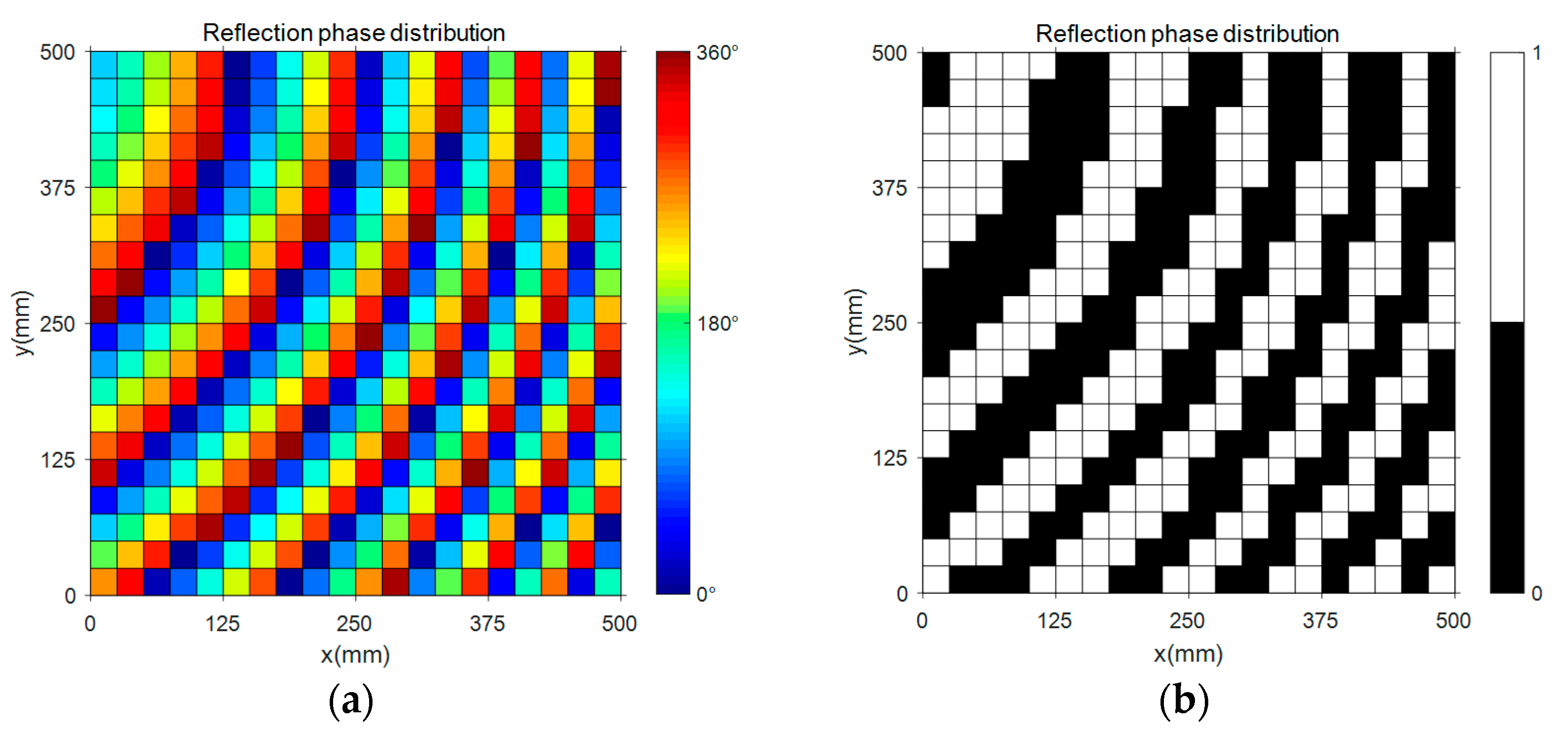
Figure 5.
Reflection phase characteristics versus frequencies (a) With different capacitance; (b) At 3.5 GHz.
Figure 5.
Reflection phase characteristics versus frequencies (a) With different capacitance; (b) At 3.5 GHz.

Figure 6.
Radiation patterns of the proposed 1-bit digital RRM at (a) ; (b) ; (c) .
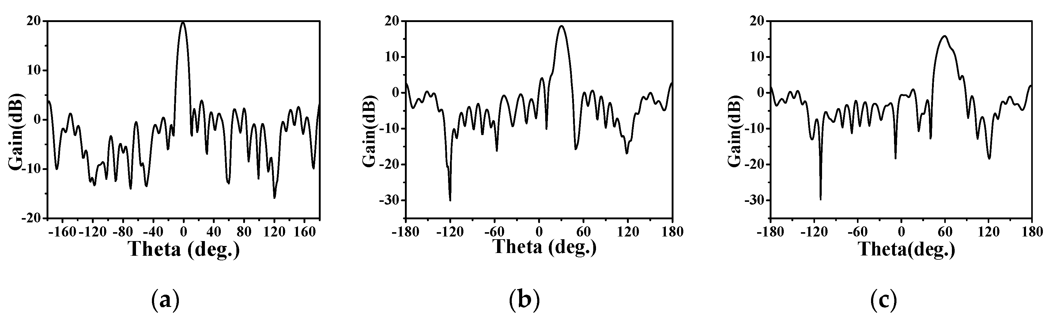
Figure 7.
Scanning main beam characteristics of the 1-bit digital RRM.

Figure 8.
Comparison of measured and simulated results of the fabricated RRM (a) Normalized radiation pattern at 3.5 GHz; (b) Gain characteristics.
Figure 8.
Comparison of measured and simulated results of the fabricated RRM (a) Normalized radiation pattern at 3.5 GHz; (b) Gain characteristics.


Table 1.
Parameters of the 1-bit digital RRM element.
| Parameter | Value | Parameter | Value |
|---|---|---|---|
| L | 25 mm | Lx | 22.5 mm |
| Gap | 0.5 mm | Ly | 22.5 mm |
Table 2.
The gain of the 1-bit digital RRM at different main beam directions and beam point errors for different scanning angles.
Table 2.
The gain of the 1-bit digital RRM at different main beam directions and beam point errors for different scanning angles.
| Gain (dB) | Beam Point Error | Gain (dB) | Beam Point Error | ||
|---|---|---|---|---|---|
| 19.89 | 0° | 16.16 | 0° | ||
| 18.65 | 0° | 15.85 | 0° | ||
| 17.59 | 0° |
© 2017 by the authors. Licensee MDPI, Basel, Switzerland. This article is an open access article distributed under the terms and conditions of the Creative Commons Attribution (CC BY) license (http://creativecommons.org/licenses/by/4.0/).
Share and Cite
MDPI and ACS Style
Tian, S.; Liu, H.; Li, L. Design of 1-Bit Digital Reconfigurable Reflective Metasurface for Beam-Scanning. Appl. Sci. 2017, 7, 882. https://doi.org/10.3390/app7090882
AMA Style
Tian S, Liu H, Li L. Design of 1-Bit Digital Reconfigurable Reflective Metasurface for Beam-Scanning. Applied Sciences. 2017; 7(9):882. https://doi.org/10.3390/app7090882
Chicago/Turabian StyleTian, Shuncheng, Haixia Liu, and Long Li. 2017. "Design of 1-Bit Digital Reconfigurable Reflective Metasurface for Beam-Scanning" Applied Sciences 7, no. 9: 882. https://doi.org/10.3390/app7090882
Note that from the first issue of 2016, this journal uses article numbers instead of page numbers. See further details here.