Optimal Control and Operation Strategy for Wind Turbines Contributing to Grid Primary Frequency Regulation

School of Energy System Engineering, Chung-Ang University, 84 Heukseok-ro, Dongjak-gu, Seoul 156-756, Korea
Appl. Sci. 2017, 7(9), 927; https://doi.org/10.3390/app7090927
Submission received: 23 June 2017
/
Revised: 29 August 2017
/
Accepted: 5 September 2017
/
Published: 8 September 2017
(This article belongs to the Special Issue Energy Saving)
Abstract
:This study introduces a frequency regulation strategy to enable the participation of wind turbines with permanent magnet synchronous generators (PMSGs). The optimal strategy focuses on developing the frequency support capability of PMSGs connected to the power system. Active power control is performed using maximum power point tracking (MPPT) and de-loaded control to supply the required power reserve following a disturbance. A kinetic energy (KE) reserve control is developed to enhance the frequency regulation capability of wind turbines. The coordination with the de-loaded control prevents instability in the PMSG wind system due to excessive KE discharge. A KE optimization method that maximizes the sum of the KE reserves at wind farms is also adopted to determine the de-loaded power reference for each PMSG wind turbine using the particle swarm optimization (PSO) algorithm. To validate the effectiveness of the proposed optimal control and operation strategy, three different case studies are conducted using the PSCAD/EMTDC simulation tool. The results demonstrate that the optimal strategy enhances the frequency support contribution from PMSG wind turbines.
1. Introduction
Over the past few years, wind energy has received significant attention as one of the most promising renewable energy sources given the adverse environmental impacts of conventional energy sources [1,2]. Both permanent magnet synchronous generator (PMSG) wind turbines and doubly fed induction generator (DFIG) wind turbines have been widely used. PMSG wind turbines are advantageous over DFIG wind turbines due to their highly reliable operation, lower maintenance expenses, and smaller weight with a simpler structure. Moreover, the PMSG can connect to the turbine without the use of a gearbox [3,4]. Therefore, many recent studies have focused on PMSG wind turbines.
In power systems with high wind power penetration, frequency control is a critical issue from the viewpoint of stable system operation. The wind power system is required to provide a reliable frequency response to support the grid and reduce costs associated with reserve power. Variable-speed wind turbines are commonly operated to achieve optimal efficiency for the maximum power output using maximum power point tracking (MPPT) control technology [5]. As a result, wind turbines do not have an inherent frequency regulation capability to supply additional reserves [6]. A sufficient reserve margin is an important requirement to participate in frequency regulation, which is absent in a wind turbine generator.
Many researchers have investigated the frequency support capability of wind turbine generators to supply the power margin. To provide an inertial response, the authors of [7,8,9] proposed an additional power control loop for variable-speed wind turbines. Further, the research in [10,11] has helped develop a concept that directs a portion of the rotational energy and blade to short-term active power support, which could aid in reducing the system frequency drop after a generation deficit. Another option is to utilize a de-loaded control operation to provide the primary frequency response. In [12], the authors suggested an operation at the de-loaded power curve of a wind turbine to supply the power margin. Various methods are available for de-loaded operations; for example, a combination of pitch angle control and rotational speed control [13,14,15,16,17]. However, increasing dynamic characteristics could affect the life of the pitch angle controller and increase the system cost. The authors of [18,19,20] considered a fixed percentage of wind turbine de-loading. De-loaded control decreases the power output of the wind turbine generator but increases the primary frequency support capability during frequency disturbances. However, de-loading is restricted to between 10% and 20%, depending on the available wind speed and rotor speed limit constraints [18]. In [21,22], the authors addressed the kinetic energy (KE) discharge control that incorporated a wind farm to supply additional reserves for frequency support.
Two options have been reported in previous studies for the participation of wind turbines during a frequency event: de-loaded control and inertial response for primary frequency control. The inertial control utilizes the KE in the rotating mass of the wind turbine to provide a temporary frequency response. The de-loaded control allows the wind turbine to run in de-loaded operation mode to reserve partial wind power for the primary and secondary frequency regulations. However, an unsuitable margin of power would rapidly decrease the rotational speed of the wind turbine. In addition, improper control of the energy regained during acceleration may cause another frequency disturbance [23]. Overall, the main focus of the previous studies has been on the frequency support capabilities of wind turbine generators. Very few published papers or documents emphasize the comprehensive frequency regulation capacity of PMSG based on rotor speed-based control under different wind speeds or enhanced inertial responses based on active power-based control when operated in MPPT mode, especially for the potential impact of frequency regulation on the mechanical components of wind turbines. Therefore, this research addresses the major issues with the goal of maximizing PMSG-WTG performance for frequency regulations in accordance with its specific operation characteristics and control structure. Concurrently, it is necessary to research a frequency regulation strategy to effectively maximize the stored KE. The authors of [24,25] suggested an operational strategy for maximizing the amount of KE during a frequency disturbance. However, these studies have not described the optimization techniques in detail.
This study proposes a new optimal control and operation strategy for a PMSG wind turbine to support system frequency in wind energy production. The machine-side converter (MSC) and grid-side converter (GSC) are designed to control the DC link voltage using vector control, and obtain maximum power output from PMSG wind turbines. The active power control operates the turbine with the MPPT and achieves the power margin through de-loaded control. Once these are achieved, the KE reserve control establishes the frequency regulation to provide stable PMSG wind turbines. To increase the contribution of wind turbines to support frequency stability via a temporary release of energy, the KE optimization method performs a KE maximization for various wind speeds using the particle swarm optimization (PSO) algorithm. The operation of PMSG wind turbines is then optimized to extract more KE, which can be released into the power system in the case of a frequency event. The optimization strategy assumes that the wind farm system performs continuous output control with monitoring and control systems for individual PMSG wind turbines. With the wind speed, this strategy calculates the maximum possible output, optimal rotational speed, and KE reserve in each wind turbine. The de-loaded power reference from an individual PMSG wind turbine that maximizes the KE reserve of the wind farm is obtained by satisfying the output command of the system operator. The frequency support capability of the PMSG system with the proposed KE reserve control strongly depends on the KE reserve obtained from the de-loaded operation and generating margin. Therefore, the frequency response of a system can be improved after organizing the de-loaded operations of individual PMSG systems with regard to the KE reserve when the wind farm is de-loaded. The KE optimization strategy, which maximizes the sum of the KE reserves at a wind farm, is adopted to determine the de-loaded power reference for each PMSG wind turbine.
The rest of this work is structured as follows. Section 2 presents the system modeling and converter control. Section 3 presents the proposed control and operation strategy to support frequency regulation using PSO. Section 4 describes a comparison of the simulation results of other cases to assess the performance of the proposed strategy. Section 5 presents the concluding remarks.
2. System Modeling and Converter Control
2.1. Wind Turbines and Modeling PMSG
The operational performance of a wind turbine can be modelled from the mathematical relationship between wind speed and mechanical power as follows:
Here, the power coefficient Cp represents the rotor aerodynamics as a function of both the pitch angle of the rotor blades and tip speed ratio (TSR).
The PMSG modeling facilitates the generation of electricity from mechanical energy and a dynamic model is derived using a two-phase synchronous reference frame, in which the q-axis is 90° ahead of the d-axis in accordance with the direction of rotation. In three-phase systems, such as PMSGs, each phase quantity has a time-varying characteristic. Using Park’s transformation, which is the projection of the phase quantities onto a rotating two axes reference frame, the AC quantities can be converted to DC quantities with time independence. The abc to dq0 transformation is represented in the matrix form:
The inverse Park’s transformation is:
In Equations (3) and (4), uabc and udq0 express the stator voltages, stator currents or flux linkages of the AC machines, respectively. Applying the equality u0 = 0 for balanced conditions, the voltage function of PMSG in the d–q axis reference frame [4] is given by
To complete the PMSG mathematical model, its mechanical equation is required [26]; the electromagnetic torque equation is described by
2.2. MSC and GSC Control
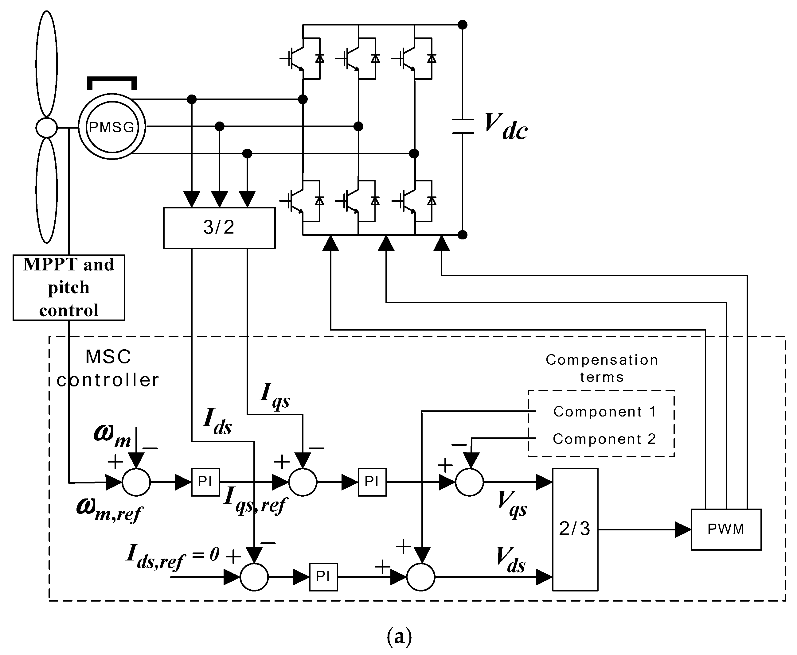
Figure 1 shows the block diagram of MSC and GSC. As shown in Figure 1a, MSC control mainly involves the adjustment of the PMSG torque and rotational speed to set the special operating conditions. The MSC can be adjusted to regulate the PMSG speed at a reference value due to the MPPT. The d–q axis current component indicates the components of torque and flux, and the stator current reference value (zero) in the d-axis is assigned to achieve maximum torque and maximize the resistive losses. The required d–q components of the voltage vector are derived from two proportional integral (PI) current controllers, which are applied to control the speed of the generator and turbine. After the PI current controllers, compensation components are added to improve the transient response, as shown in Figure 1. Components 1 and 2 are and , respectively. They are obtained from Equations (5) and (6). The Park and Clarke transformations are applied to the d- and q-components to generate the three-phase current references for the MSC. The speed reference, calculated from Equation (2), is restricted to the maximum angular speed (3.5 rad/s). Here, we use pulse width modulation (PWM) to produce a switching signal for MSC control.
As shown in Figure 1b, GSC control maintains a constant DC link voltage regardless of the magnitude of PMSG power and generates any reactive power to obtain a power factor of unity. To develop the control mode for GSC, a vector control method is applied with a reference frame of the grid voltage, utilizing independent control of the active power and reactive power between the GSC and grid.
The voltage equations for the dynamic model of the grid connection in the d–q reference frame [27] can be expressed as
The q-axis current component of the GSC is used to control the flow of the reactive power, and the d-axis current component of the GSC is used to regulate the DC link voltage using a PI controller. In this study, the grid q-axis current is set to zero to prevent generation of any reactive power. A phase-locked loop (PLL) circuit is applied to synchronize the three-phase voltage with the grid voltage. To transfer all the active power obtained from the wind turbine to the grid, the DC link voltage should remain constant, as shown in the following constraint [5].
If the wind turbine power and the grid power are equal, the DC link voltage must be constant. Compensation components guarantee stable and decoupled active and reactive power control. Components 1 and 2 are and , respectively. These terms can be added to enhance the transient response of the power system (Equations (8) and (9)).
3. Proposed Optimal Strategy
3.1. Control Mode of Wind Turbine
3.1.1. Active Power Control
Maximum power point tracking (MPPT) control is usually employed to maximize the energy conversion efficiency of a wind turbine by regulating the rotational speed of a variable-speed wind turbine. Depending on the wind aerodynamic conditions, an optimal operating point exists that may allow the extraction of maximum power from the turbine. This point is called the maximum power point (MPP). The power captured with the wind turbine can be substantially maximized by adjusting the coefficient Cp, which represents the aerodynamic efficiency of the wind turbine and is dependent on the TSR λ. The wind turbine can generate maximum power as expressed in Equation (1). Then, the maximum mechanical output power of the turbine is given by
The optimal TSR of the mechanical output power can be represented as follows:
For the PMSG wind turbine, the maximum value of the power coefficient (Cp,opt = 0.4412) is obtained as an optimal value of TSR (λopt = 6.9), calculated using Equation (14). The coordination of TSR to its optimal value with the power coefficient reaching Cp,opt guarantees maximum power extraction. Equation (15) provides the formulation for maximum power determined using the MPPT control:
with
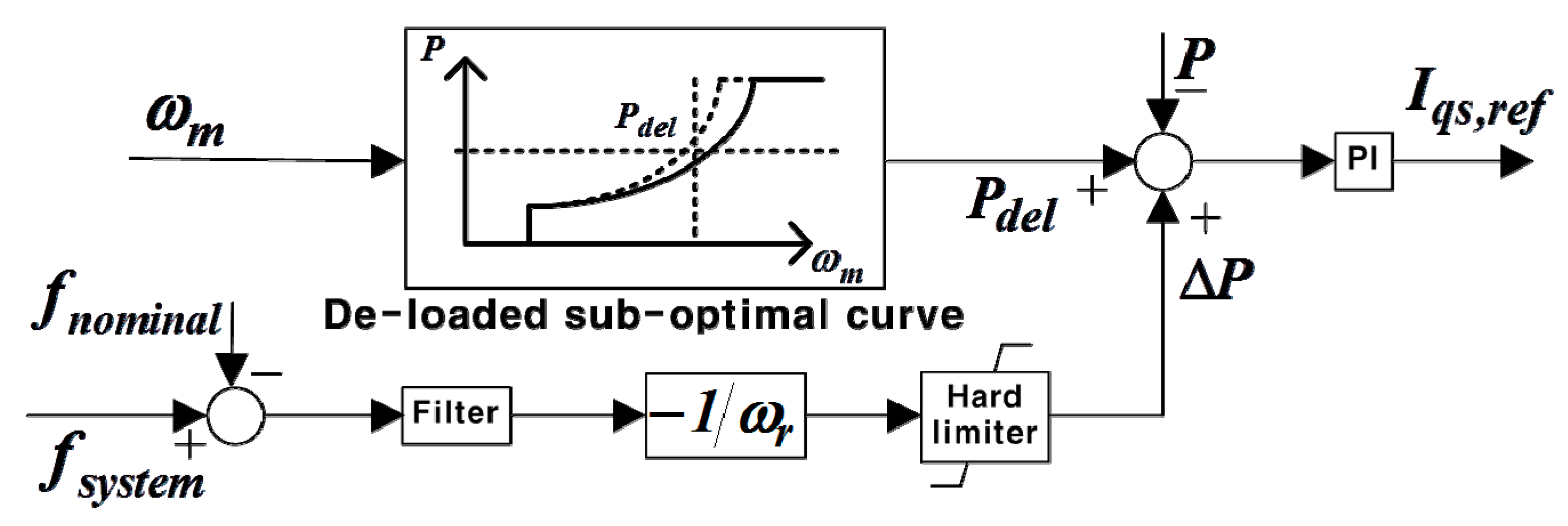
This MPPT control allows the wind turbine to extract as much power as possible for each wind speed. However, when the power system begins to impose requirements on the wind power for objectives, such as frequency regulation, other operational modes are required. For wind turbine generators to improve in frequency support capability, they must secure sufficient reserves. In this study, the PMSG wind turbines are operated at the de-loaded power point (over speeding) instead of at the MPP. The de-loaded control mode can also be implemented using a combination of control techniques for rotational speed and pitch angle. Figure 2 shows the MPPT and de-loaded power extraction curves for a PMSG wind turbine at various wind speeds. In setting the maximum de-loaded values for a PMSG wind turbine, both the current rating of the converters and maximum allowable limit of the rotational speed need to be considered. In the 5% de-loaded control for a PMSG wind turbine, the power output is Pdel = 0.95Pmax. To provide a reliable operation range of PMSG, this study focuses on the maximum rotational speed of 1.2 p.u., with a reduction in certain fatigue loads as an additional objective. Figure 3 shows the de-loaded controller. To utilize the proposed de-loaded control mode, the power margin Pmargin of a wind turbine is represented as follows:
3.1.2. KE Reserve Control
To provide additional active power to the grid, the KE reserve control utilizes the energy stored in the rotating masses of the generator. This concept has the advantage of being able to make a relatively large contribution to short-term frequency control. However, excessive discharge of KE with the aim of making a large contribution continuously during the participation of the wind turbine in frequency regulation not only decreases the rotational speed of the wind turbine significantly, but it may also make the wind turbine unstable. Therefore, for stable operation of a PMSG wind generator, it is crucial to appropriately set the output provided to the system during frequency control. In this study, the KE reserve control for frequency support is used along with the de-loaded control to supply the amount of power reserve for the primary frequency response.
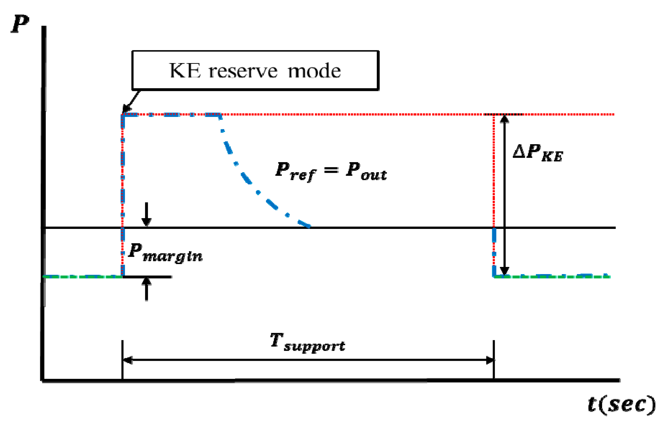
Figure 4 shows a diagram of the proposed KE reserve control method. de-loaded control makes the rotational speed increased with to the optimal rotational speed for a given wind speed, and it means that the KE stored in rotating masses is also increased when PMSG system is de-loaded. Figure 5 shows the KE reserve controller. If the frequency decreases because of frequency disturbance in the power system, de-loaded control mode switches to KE reserve mode using KE reserve control. This change immediately increases the output Pdel of the PMSG as the power increment ∆PKE, and maintains its output by participating in frequency regulation during a support time Tsupport. In other words, Pout is increased by ∆PKE and the rotational speed decreases because of KE reserve control.
Because the rotational speed at the de-loaded power point is higher than the optimal rotational speed, the de-loaded control can significantly increase the KE reserve, which is given by
3.1.3. Pitch Angle Control
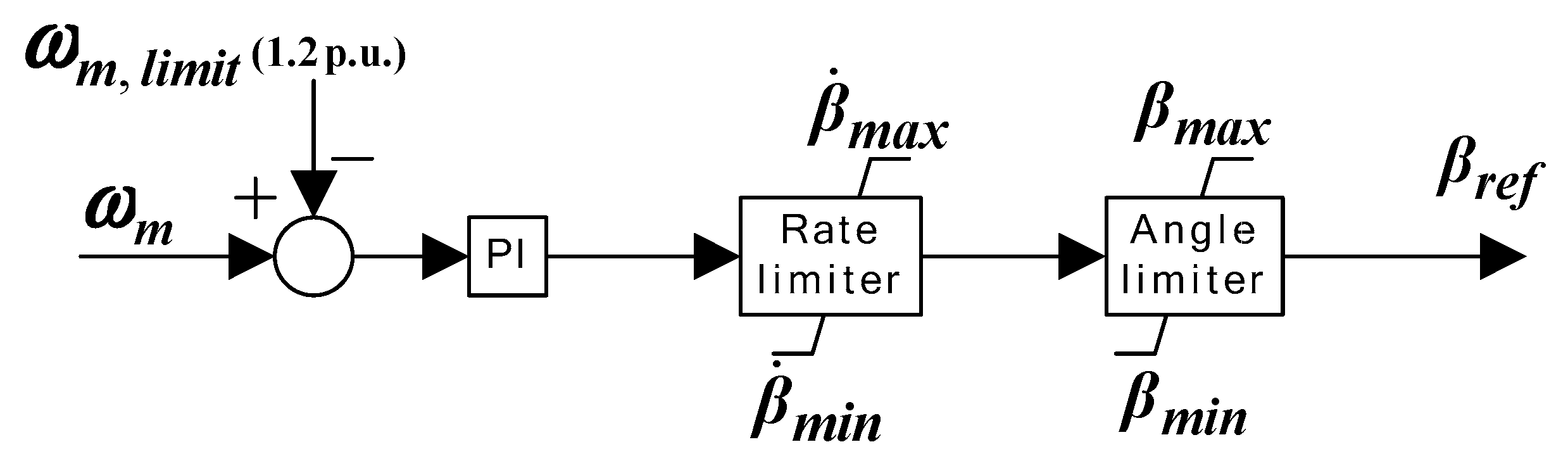
When the wind speed is above the rated speed, the pitch angle control mode adjusts the pitch angle thereby reducing the power obtained from the wind. Figure 6 shows the pitch angle controller, which is based on a PI control for processing the error between the rate value and angular speed of the generator/turbine. When the wind turbine operates with a power optimization strategy or power limitation, this control mode limits the rotational speed to maintain a reliable operation range for the PMSG. This work focuses on the maximum rotational speed of 1.2 p.u. with a reduction of certain fatigue loads as an additional objective. This controller adjusts the pitch angle based on a comparison of ωm. The reference pitch angle βref is determined by the PI controller. The operating rotational speed must be limited between 0.7 and 1.2 p.u. The pitch angle control of a PMSG wind turbine can be summarized as follows:
- Optimization of the power output of the wind turbine
- Prevention of excessive rotational speed and mechanical power above the rated wind.
3.2. KE Optimization Method
3.2.1. Operation Scheme
For effective utilization of the stored KE, it is essential to understand the influenced of the operating point. The operation scheme that utilizes the KE control as a fast reserve is adopted in the proposed optimal strategy. In normal operation, a PMSG wind turbine acts in the MPPT mode, which is the most economically viable mode. However, to actively participate in frequency control, the PMSG wind turbine operates at the de-loaded power extraction curve. In the event of a severe frequency drop, the de-loaded control mode is changed to the KE reserve discharging mode with a trigger signal. The output Pout of the wind turbine increases as ∆PKE, and the KE reserve mode maintains the output command using the de-loaded control during the support time.
The purpose of the proposed KE optimization method is to first, improve PMSG performance in terms of frequency regulation capability and second, maximize the KE reserve while determining the de-loaded power reference for active power control of the wind farm. When operating under frequency support control, the KE reserve obtained from the individual PMSG wind turbines can be calculated using Equation (18). Assuming that the wind farm consists of N wind turbines operating at different wind speeds, the total KE reserve of the wind farm can be expressed as
Here, ωdel,i and ωm,opt,i are the de-loaded rotational and optimal rotational speeds in the ith PMSG wind turbine, respectively. The KE reserve mode can discharge a much greater amount of KE than a conventional plant of the same rating and inertia. The rotational speed deceleration resulting from the KE discharge can be calculated according to the following equation.
The active power control can immediately control the active power output of a PMSG wind generator () according to the command determined in the system. Because the mechanical input Pm of wind energy in a turbine blade of the wind generator is only determined from the given wind speed and rotational speed, Pm is not instantly changed from the active power control. Controlling the output of the PMSG wind turbine generator results in the rotational speed changing with the difference between the mechanical power input and active power output. If the mechanical input and actual output of the wind turbine balance, the rotational speed is stabilized and the wind turbine operates at the corresponding operation point.
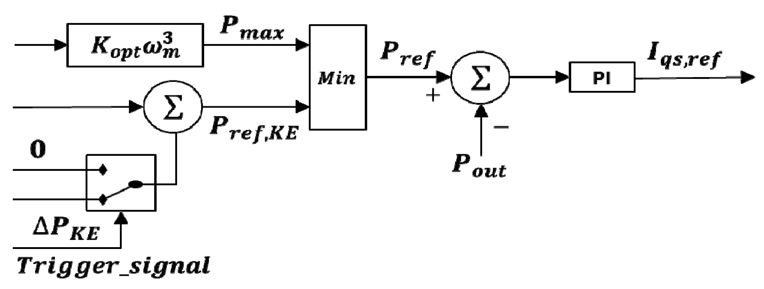
Figure 7 shows the modified q-axis rotational current control loop for the proposed frequency support control. The wind turbine would require a detection scheme to analyze the frequency drop. The trigger signal for switching to the KE reserve is obtained from the variance in the frequency. Figure 8 shows the triggering scheme and frequency detection employed in the proposed frequency support control. In general, when the frequency of the system decreases because of an accident, it is very difficult to determine the scale of the actual accident or severity of the frequency problem until the frequency is restored. A misjudgment by the frequency detector may cause other frequency problems due to the frequency support control of the PMSG wind turbine. To prevent this problem, the frequency detector determines the trigger signal by prioritizing the frequency change rate of the system. All wind turbines simultaneously recognize the frequency deviation using an event detector. The rate of change of frequency (ROCOF) [28] can be obtained as
Here, fsystem is a system frequency and fnominal is the nominal frequency (60 Hz). Equation (21) represents the amount of required active power that can be computed using the ROCOF and indicates the security index of the grid disturbance. When the frequency of the system continuously decreases below a frequency standard, the frequency detector continuously provides the trigger signal to regulate the system frequency.
3.2.2. Optimal KE Solution
The KE optimization problem in this study is solved using PSO [29], which is adopted for optimal tuning of the KE reserve value for each wind farm. Maximizing the additional KE can be translated into optimizing for rotational speed in the de-loaded control. The purpose of the proposed KE optimization method is to maximize the KE reserve defined in Equation (19). Here, because the optimal rotational speed, ωm,opt,i, is a constant value determined from wind speed, the objective function of the KE optimization problem is defined as
The objective function is aimed at ensuring that generators maximize their KE reserve from the stored rotor, while performing the active power control to support the frequency of the power system. For enhancing the frequency support capability of wind farms, the main issue of this paper realizes KE optimization method to determine the de-loading power value reference for each PMSG systems [15,16], and maximizes the sum of KE reserve value through Equation (22). When the wind farm operates according to the system operator’s output command Pref,wf, the de-loaded power reference Pdel,i and de-loaded rotational speed ωdel,i of the individual PMSG wind turbine determined in the control system must satisfy the following constraints.
Total power output constraints of the wind farm:
Power output constraints of PMSG wind turbines:
Rotational speed constraints of PMSG wind turbines:
When the wind turbines operate at the proposed de-loaded control, the output of the PMSG wind turbine is kept constant according to the de-loaded power reference. Thus, the sum of the de-loaded references of individual wind turbine generators, Pdel,i should be equal to the output of the wind farms according to the output command of the system operator Pref,wf, which sets the output of the wind farm for stable system operation. The minimum possible power is defined in the range that can maintain stable wind power operation for a given wind speed. When a wind turbine is operated in the de-loaded control mode, the rotational speed reference must be determined within the range of constraints. From Equation (25), the minimum rotational speed is limited from the optimal rotational speed in the MPPT control mode, and the maximum rotational speed of all wind turbines is set to the rotational speed reference of pitch angle control.
3.2.3. PSO Algorithm
In this work, the PSO is applied to find the global solution to the KE optimization problem in Equations (22)–(25). Each feasible solution of the problem is termed a particle, which is assigned a random velocity and flown through the problem space. The ith particle of the swarm in the d-dimensional search space can be represented by its position xi and velocity vi. Each particle keeps track of its previous best position (pbest) and the best performing particle of the swarm is termed the global best (gbest). According to the particle’s previous best experience and the best experience among the particles in its neighborhood, the speed and direction of the particle velocity are updated [30,31]. Mathematically, this algorithm is formulated as follows:
The variable represents the personal best position attained by the d-dimensional quantity of the individual “i” from among its “t” times of occurrence, and denotes the d-dimensional quantity of the best position attained globally by the swarm. New position and velocity vectors are determined for each particle by combining its previous velocity with and (Equations (26) and (27)). The initialization process for the velocities and positions of the particles is conducted by using vectors of random numbers. Here, each wind turbine is considered to be a particle while the whole complex of wind turbines is modeling the swarm. In other words, the deloaded power outputs of wind turbines are regulated as the particles of a swarm to achieve different possible answers for the problem. It means that the number of wind turbines is equal to the number of particles of the swarm.
Inertial weight w is the modulus that controls the impact of previous velocity on the current one, thus practically, an appropriate selection of the inertial weight is requested to optimize for diverse wind speeds and distribute across all operating areas of the wind farm. The inertia weight may be increased if the objective values of particles close to accordance or tend to local optimal. Conversely, the inertia weight could be decreased. In this work, the inertial weight calculation according to number of iterations can be written as
Moreover, in order to permit the algorithm to avoid falling into local minima and search in the whole optimization space, and improve the algorithm accuracy and convergence speed, the acceleration coefficients in the searching process are controlled as follows:
During the updating, the particle position xi and velocity vi are limited in the available range. When the maximum number of iterations or the performance index is reached, the output gbest is the global optimal solution.
3.3. Procedure of Optimization Strategy
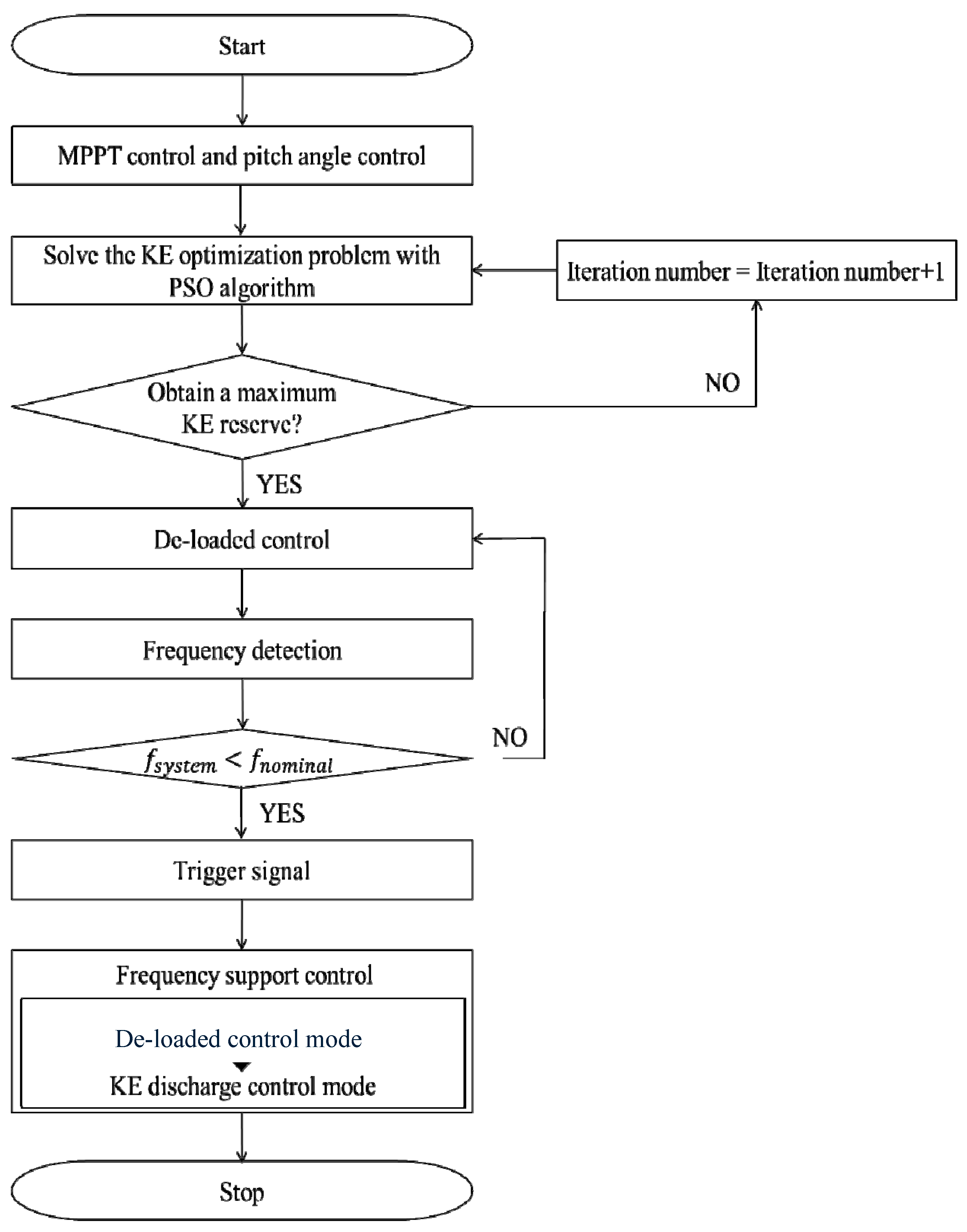
The proposed strategy focuses on the frequency regulation capability of the PMSG wind turbine. As shown in Figure 9, the procedure for the proposed optimal strategy is described as follows:
- Obtain the maximum power using the MPPT and pitch angle control based on the converter control.
- Optimize the KE reserve to improve the frequency support capability of the PMSG wind turbine. The KE optimization problem is solved using the PSO algorithm, which maximizes the sum of the KE reserves to determine the de-loaded control power reference for each wind farm. If the number of iterations is maximized, the optimal decision value is used to maximize the KE reserve.
- Operate at the de-loaded power point to maintain a certain power margin and ensure an additional KE reserve. The regulation margin is available to support the system frequency in a transient duration.
- Check the change in the system frequency caused by the loss of generators and disturbance. In addition, monitor the frequency deviation of the power system. If the frequency deviation problem (low frequency) occurs in the power system, then go to Step 5. Otherwise, if the measured frequency is higher than the nominal frequency, the system operator provides a new command to the de-loaded control and reduces the output of the conventional generators. When the power system is stable, return to Step 3.
- In the event of a frequency disturbance, switch the control of the trigger signal from the de-loaded control to the KE discharge control. The frequency regulation control utilizes the additional reserves due to the KE stored in the PMSG wind turbine and rotor.
- If the operation in the power system is stabilized from the compensation, end the procedure.
4. Case Study
4.1. Data and Parameter Setting
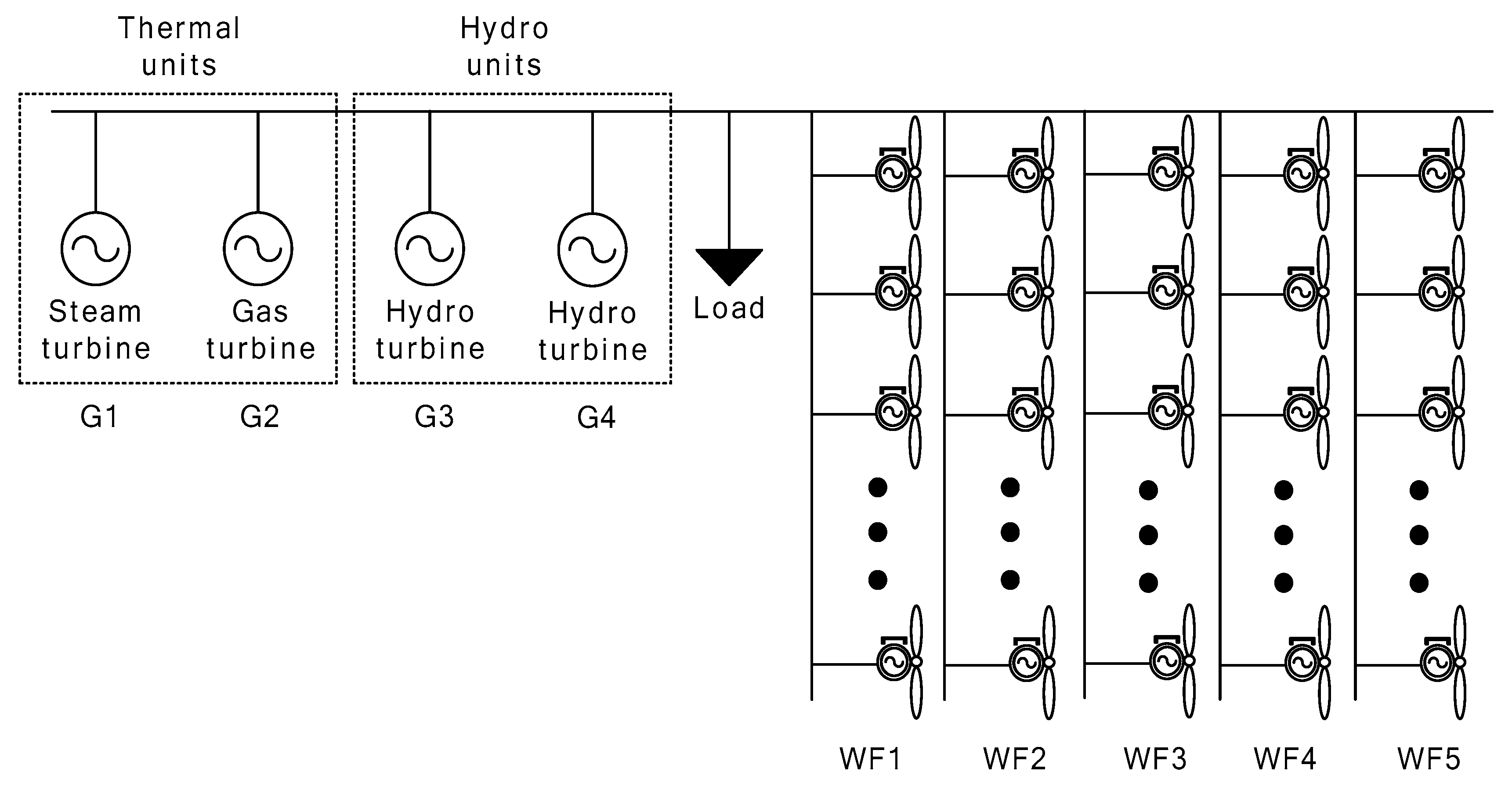
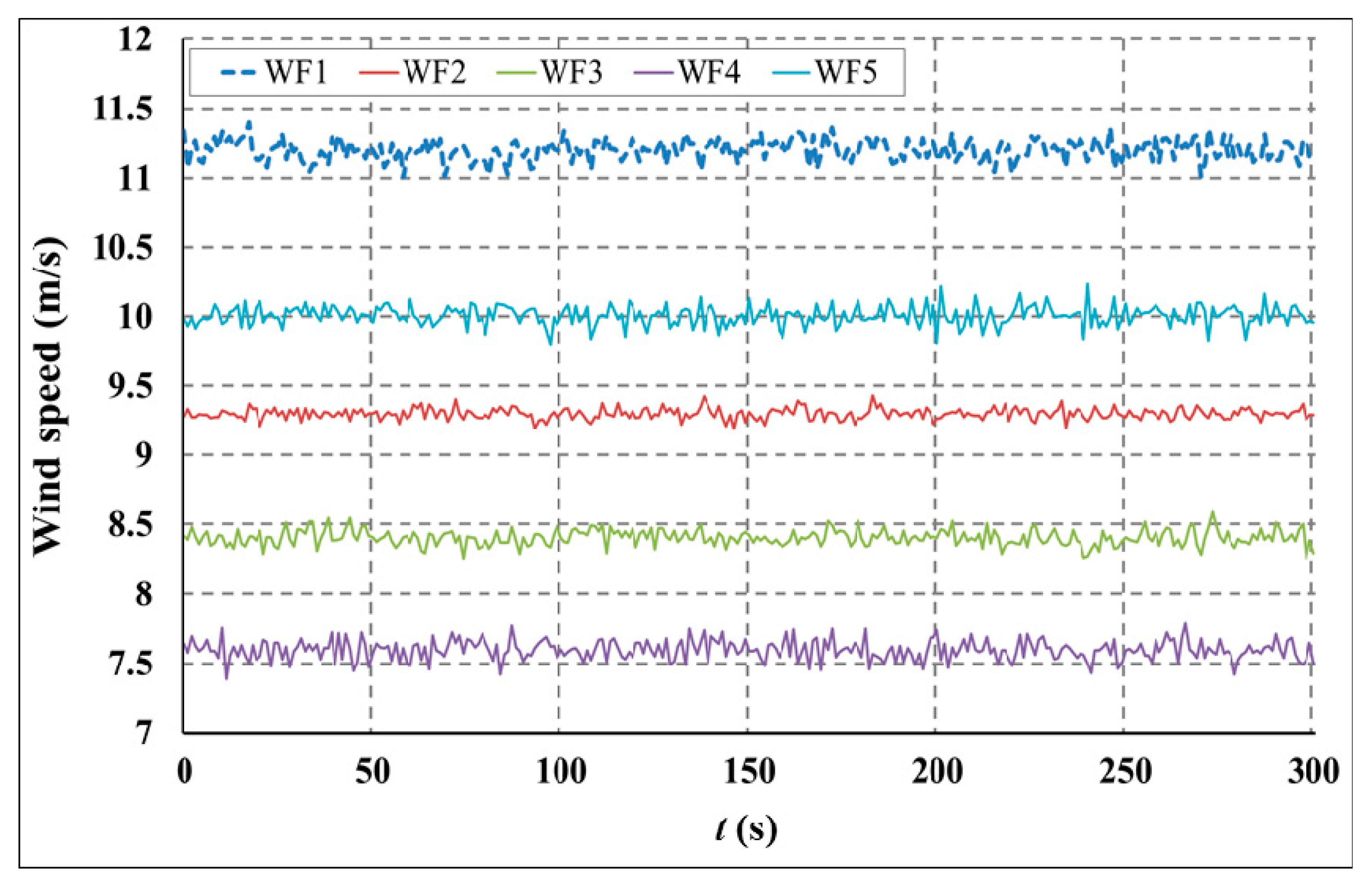
The validity of the proposed optimal control and operation strategy was demonstrated by applying it to a simulated power system, as illustrated in Figure 10. This system is composed of thermal units, hydro units, and wind farms. The thermal units are combined with a gas turbine G2 (50 MW) and steam turbine G1 (100 MW). The hydro units have two hydro turbines G3 and G4, rated at 70 MW and 60 MW, respectively. The load is based on modeling to represent a linear frequency dependency on the active power characteristics. Wind farms WF1–WF5 (each 16 MW) were linked to the small power system and an individual wind farm consists of eight PMSG wind turbines (each 2 MW). To solve the KE optimization problem, the maximum iteration number in the PSO is set to 100, and the population size is set to 50. r1 and r2 are uniform random factors with assigned values between 0 and 1 in each step and for each particle component to add randomness to the velocity update. The inertial weight w is set to reduce from 0.9 to 0.4 in different iterations. Each of the acceleration coefficients, c1 and c2, is set to between 0.5 and 2.5 to achieve a mean value of unity for the stochastic factor [30]. Based on the characteristics of the wind turbine, Figure 11 depicts the correlated wind speed profiles for individual wind farms in the small power system. These results are simulated using the PSCAD/EMTDC tool by adopting the parameters described in the Appendix A.
4.2. Simulation Results
The performances of the PMSG wind farms in three different cases are compared to verify the effectiveness of the proposed optimal strategy.
Case 1: No frequency support control;
Case 2: Frequency support control (5% de-loaded operation) without using the KE optimization method;
Case 3: Frequency support control using the KE optimization method (proposed strategy).
In Case 1, none of the wind farms utilize the reserve margin for supporting regulations with frequency control and active power. The PMSG wind turbines are operated only at the maximum aerodynamic efficiency and the pitch angle is then retained at the optimal value. In Case 2, the PMSG wind turbines participate in frequency regulations using a fixed 5% de-loaded operation based on frequency support control without using the KE optimization method. In Case 2, the active power outputs from all wind farms are subjected to the same power reduction according to a fixed de-loaded reference. To enhance the frequency contribution of the PMSG wind turbines, Case 3 implements an additional KE optimization method to maximize the total KE in the rotor. In this case, each individual wind farm operates in the de-loaded control mode to optimize the additional KE generated from the wind turbine under consideration.
In this work, an initial system is considered where all synchronous units are operated in accordance with the parameters listed in Table 1. Here, the active load power is 270 MW. The steam turbine G1 maximizes the output from power generation as a base generator in a small power system. The overall capacity of the wind farms represents approximately 28% of the total installed generation capacity. It is assumed that at t = 100 s, the system operator requests the power output reference for all wind farms to be approximately 40 MW. The columns in Table 2 represent the wind speed, maximum power, optimal rotational speed, and de-loaded power reference of individual wind farms in the three cases. The power outputs in Case 2 and Case 3 satisfy the power reference requirement specified by the system operator.
Table 3 presents a comparison of the results of the additional KE reserve values in wind farms for the three cases. The additional KE in Case 3 can supply a greater power output to the power system than the KE in Case 2. When PMSG wind turbines operate at a near-rated wind speed, the rotational speed is also restricted by the maximum value generated from the pitch angle control (1.2 p.u.). As shown in Table 3, the rotational speed of the WF1 in Case 2 is limited to maximum rotational speed of 1.2 p.u. (ωdel) through pitch angle control. Besides, the rotational speed of the WF1 and WF5 in Case 3 are restricted by pitch angle control. The de-loaded power reference for Case 3 increases the KE reserve considerably. The application of the output control using the KE optimization method can enhance the capability of the frequency regulation.
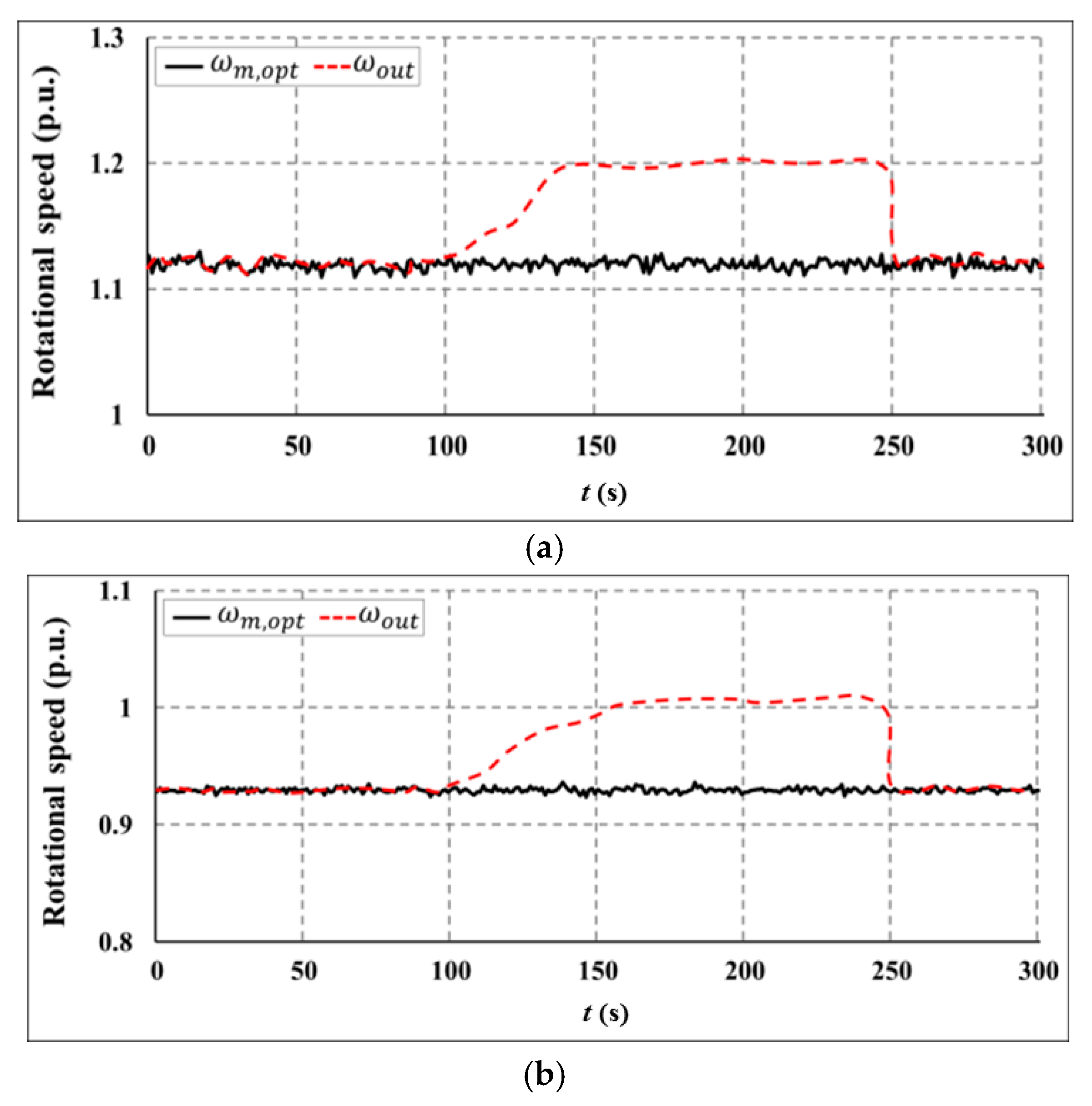
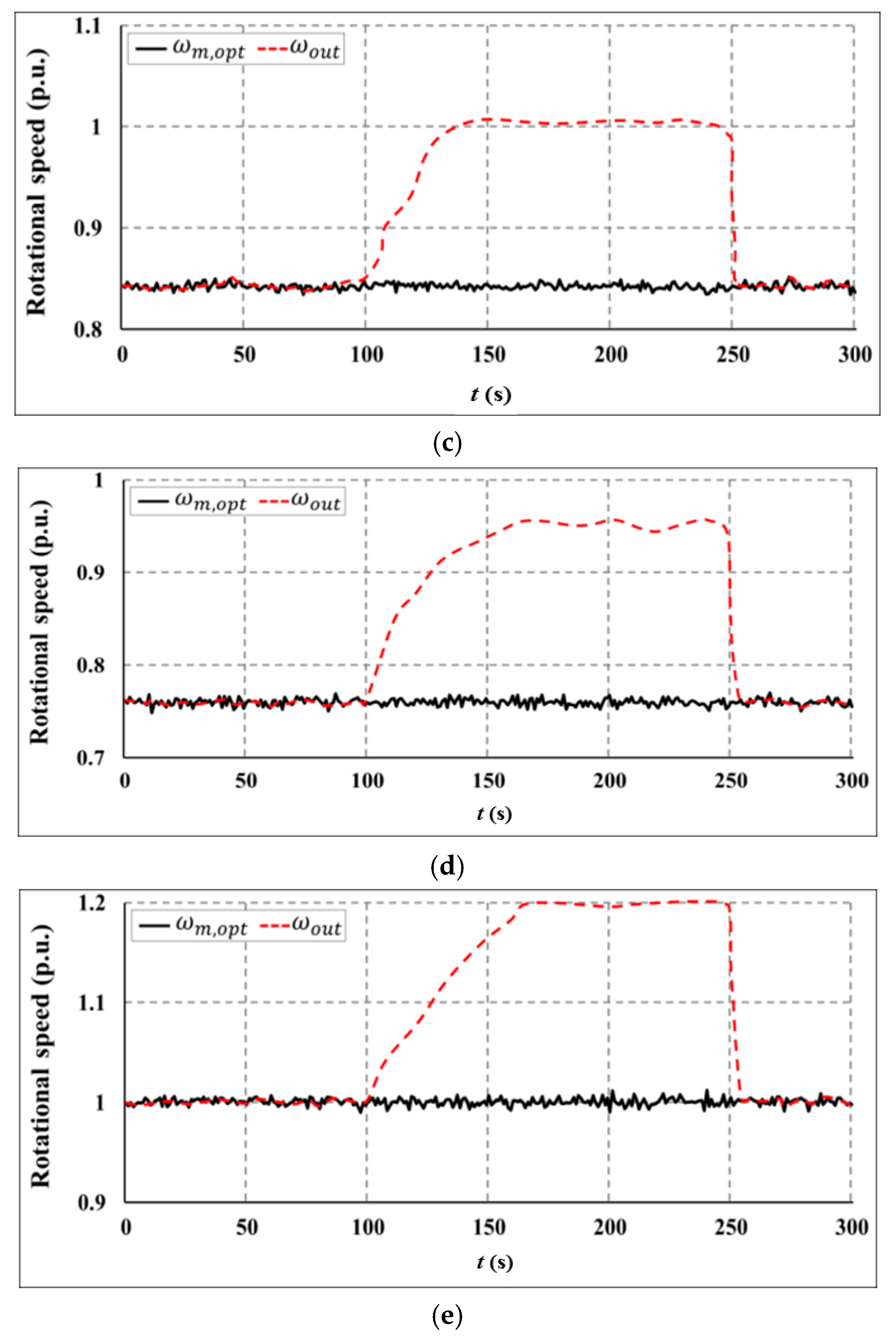
To evaluate the frequency contribution of the proposed optimal strategy, the loss of G2 is determined at t = 250 s in such a way that it promotes a change in the frequency of the power system. When the frequency drops owing to the loss of G2, wind farms are simulated to support the frequency regulation in the test system. Figure 12 and Figure 13 illustrate the variations in the active power output and the rotational speed in Case 3, respectively. Since the rotational speed of WF1 and WF5 is limited to 1.2 p.u. by pitch angle controller, it is noted that the rotational speed are appropriately controlled within the available range (0.7–1.2 p.u.). Each wind farm operates in the MPPT control mode after exhaustion of the KE reserve and offers additional power output to participate in frequency control during the support time.
Figure 14 presents a comparison of the system frequency responses during a disturbance in the three cases. When frequency drops because of the disturbance, the minimum frequency responses of Case 1 and 2 are 59.63 Hz and 59.75 Hz, respectively. Then, the grid minimum frequency of Case 3 is 59.78 Hz. Therefore, Case 3, i.e., the proposed strategy, can provide the greatest support to improve the minimum grid frequency among all the cases. It may also help in enhancing the robustness of the power system by decreasing the frequency fluctuations under a given load. As shown in Figure 14, the frequency recovery of the proposed strategy is much faster than that of Case 1 and 2, and hence, Case 3 can provide more power to enhance the frequency response of power system. Case 3 can also accomplish a greater development of the frequency support capability of PMSG wind turbines using the PSO-based optimization process for the KE reserve. Consequently, it should be noted that the proposed optimal control and operation strategy can considerably enhance the ability of initial and low-frequency responses in the short-term frequency regulation.
5. Conclusions
This study investigated the performance of an optimal control and operation strategy for PMSG wind turbines to improve their frequency support capability in a power system. The PMSG wind generation system was constructed including PMSG modeling and integrated MSC and GSC controls. The PMSG wind turbine control is implemented using relevant direct and quadrature component controls on the rotor voltage, implemented using converters. The active power control in this study focused on the MPPT control to extract optimal power and the de-loaded control to obtain the power margin. The KE reserve control was also applied to enhance the frequency support capability. To improve the contribution of a wind turbine to support stable frequency regulation via the temporary release of more KE, the KE optimization method was applied using the PSO algorithm. It can be observed from the case study that the results validate the proposed strategy for the PMSG given the modeled frequency variations. In the proposed optimal strategy, the frequency regulation capability of the PMSG wind turbine depends on the additional KE reserve generated from the optimization process and the power margin. De-loaded control prevented the wind system instability that may have resulted from excessive KE discharge. The results demonstrate that the proposed strategy can restrict the frequency drop while decreasing the disturbances across the overall operational scale of PMSG wind turbines. Consequently, the proposed optimal strategy can significantly enhance the system contribution to the frequency regulation capability of wind turbines. Further research work will concentrate in solving optimization problem about the control strategy to account for PMSG wind turbines, compared with the benchmark optimization algorithms.
Acknowledgments
This research was supported by Basic Science Research Program through the National Research Foundation of Korea (NRF) funded by the Ministry of Education (2017R1D1A1B03029308). This research was also supported by Korea Electric Power Corporation through Korea Electrical Engineering & Science Research Institute (grant number: R15XA03-55).
Author Contributions
Mun-Kyeom Kim contributed this manuscript solely.
Conflicts of Interest
The author declares no conflict of interest.
Nomenclature
| Blade pitch angle | |
| Reference value of pitch angle | |
| βmax, βmin | Maximum and minimum values of pitch angle |
| Air density (=1.205 kg/m2) | |
| Tip speed ratio | |
| Optimal tip speed ratio | |
| B | Friction coefficient of generator |
| Cp | Power coefficient of wind turbine |
| Cp,opt | Optimal power coefficient of wind turbine |
| Sw | Wind speed |
| J | Moment of inertia of wind turbine (kg/m2) |
| Vdc | DC link voltage |
| Vdc,ref | Reference value of DC link voltage |
| Vdi, Vqi | Inverter voltages in d–q axis |
| Vds, Vqs | Stator voltages in d–q axis |
| Vdg, Vqg | Grid-side voltages in d–q axis |
| Ids, Iqs | Stator currents in d–q axis |
| Ids,ref, Iqs,ref | Reference value of stator currents in d–q axis |
| Idg, Iqg | Grid-side currents in d–q axis |
| Idg,ref, Iqg,ref | Reference values of grid-side currents in d–q axis |
| θr | Electrical angle between a-axis and q-axis (rad) |
| u | Any of the variable (voltage, current, and flux linkage) to be transformed from the abc frame to dq frame |
| Rs, Rg | Resistances of PMSG winding and grid sides |
| Te | Electromagnetic torque |
| Tm | Mechanical torque |
| Magnetic flux | |
| C | Capacitance of DC link capacitor |
| Ld, Lq | Machine inductances in d–q axis |
| Ls, Lg | Inductances of PMSG winding and grid sides |
| pn | Number of pole pairs |
| ωdel | Reference value of rotational speed of de-loaded control |
| ωe | Electrical rotational speed |
| ωg | Rotational speed of grid side |
| ωm | Mechanical rotational speed |
| ωm,limit | Maximum limited rotational speed |
| ωm,opt | Optimal rotational speed |
| ωm,ref | Reference value of mechanical rotational speed |
| ωout | Rotational speed output |
| ωt | Rotational speed of turbine |
| R | Rotator radius |
| Pm | Mechanical power |
| Pt, Pg | Active powers of wind turbine and grid side |
| Pmax, Pmin | Maximum and minimum possible powers |
| Pmargin | Power margin |
| Pout | Active power output |
| Pref | Reference value of active power |
| Pdel | De-loaded power reference |
| Pref,KE | Reference value of KE power |
| Pref,wf | Reference value of active power of wind farm |
| N | Number of PMSGs in wind farm |
| Δ PKE | KE power increment |
| Δ Ploss | Lacking active power under grid fault |
| Qg | Reactive power of grid side |
| Qref | Reference value of reactive power |
| Kdel | Rotational speed coefficient of de-loaded control |
| Kopt | Coefficient of rotational speed for maximum power |
| KEres | Kinetic energy (KE) reserve |
| KEres,wf | Total KE reserve of wind farm |
| Hsystem | Equivalent inertia of entire power system |
| fsystem | Frequency of power system |
| fnominal | Nominal frequency (60 Hz) |
| fref | Reference value of frequency |
| Velocity along dth dimension of ith particle in iteration t | |
| Current position along dth dimension of ith particle in iteration t | |
| pbest, gbest | Best positions for individual and swarm particles |
| r1, r2 | Random numbers between 0 and 1 |
| c1, c2 | Acceleration coefficients |
| c1,max, c1,min | Maximum and minimum value of the c1 |
| c2,max, c2,min | Maximum and minimum value of the c2 |
| w | Inertial weight |
| wmax, wmin | Maximum and minimum value of the inertial weight |
| t | Current iteration |
| tmax | Maximum number of iterations |
Appendix A. Simulation Parameters

Table A1.
Wind turbine parameters.
| Parameters | Notation | Value |
|---|---|---|
| Blade radius | R | 38 m |
| Air density | ρ | 1.205 kg/m2 |
| Optimal power coefficient | Cp,opt | 0.4412 |
| Rated wind speed | Sw,rated | 12 m/s |
Table A2.
PMSG generator parameters.
| Parameters | Notation | Value |
|---|---|---|
| Rated generator power | Pm,rated | 2 MW |
| Rated RMS line-to-line voltage | Vm,rated ρ | 0.69 kV |
| Rated machine speed | ωm,rated | 376.99 rad/s |
| Pole pairs | P | 11 |
| Generator and turbine inertia constant | H | 5.7267 s |
| PM flux | Ψf | 136 Wb |
| Stator d-axis inductance | Lmd | 0.334 H |
| Stator q-axis inductance | Lmq | 0.217 H |
| Stator leakage inductance | Lsi | 0.0334 H |
| Stator resistance | Rs | 0.08 Ω |
Table A3.
Steam turbine synchronous generator parameters.
| Notation | Value | Notation | Value |
|---|---|---|---|
| H | 5.4 s | Xl | 0.161 p.u. |
| Xd | 1.456 p.u. | Xq | 1.405 p.u. |
| Xd′ | 0.206 p.u. | Xq′ | 0.500 p.u. |
| Xd″ | 0.147 p.u. | Xq″ | 0.147 p.u. |
| 3.735 s | 0.305 s | ||
| 0.032 s | 0.080 s |
Table A4.
Gas turbine synchronous generator parameters.
| Notation | Value | Notation | Value |
|---|---|---|---|
| H | 1.86 s | Xl | 0.15 p.u. |
| Xd | 1.94 p.u. | Xq | 1.92 p.u. |
| Xd′ | 0.2259 p.u. | Xq′ | 0.402 p.u. |
| Xd″ | 0.1723 p.u. | Xq″ | 0.1723 p.u. |
| 10.4 s | 0.83 s | ||
| 0.03 s | 0.055 s |
Table A5.
Hydro turbine synchronous generator parameters.
| Notation | Value | Notation | Value |
|---|---|---|---|
| H | 2 s | Xl | 0.12 p.u. |
| Xd | 2.102 p.u. | Xq | 1.95 p.u. |
| Xd′ | 0.246 p.u. | Xq′ | 0.502 p.u. |
| Xd″ | 0.16 p.u. | Xq″ | 0.263 p.u. |
| 11.2 s | 0.93 s | ||
| 0.034 s | 0.07 s |
Table A6.
PI parameters.
| Controller | kp | ki |
|---|---|---|
| MSC | 0.29 | 12.48 |
| GSC | 0.71 | 7.23 |
| DC-link | 0.002 | 0.05 |
| Pitch angle | 150 | 25 |
| De-loaded | 2.12 | 0.21 |
References
- Rodrigo, T.P.; Sílvio, F.R.; Edwin, W.; Ricardo, S.; Pavol, B.; Jan, P. Operation and Power Flow Control of Multi-Terminal DC Networks for Grid Integration of Offshore Wind Farms Using Genetic Algorithms. Energies 2013, 6, 1–26. [Google Scholar]
- Alexander, K.; Bruno, U.S.; Lueder, V.B. Curtailment in a Highly Renewable Power System and Its Effect on Capacity Factors. Energies 2016, 9, 510. [Google Scholar] [CrossRef]
- Mohamed, A.; Ralph, K. Fault-Ride through Strategy for Permanent-Magnet Synchronous Generators in Variable-Speed Wind Turbines. Energies 2016, 9, 1066. [Google Scholar] [CrossRef]
- Hong, C.M.; Chen, C.H.; Tu, C.S. Maximum power point tracking-based control algorithm for PMSG wind generation system without mechanical sensors. Energy Convers. Manag. 2013, 69, 58–67. [Google Scholar] [CrossRef]
- Xiaolian, Z.; Can, H.; Sipeng, H.; Fan, C.; Jingjing, Z. An Improved Adaptive-Torque-Gain MPPT Control for Direct-Driven PMSG Wind Turbines Considering Wind Farm Turbulences. Energies 2016, 9, 977. [Google Scholar] [CrossRef]
- Doherty, R.; Mullane, A.; Nolan, G.; Burke, D.J.; Bryson, A.; Malley, M.O. An assessment of the impact of wind generation on system frequency control. IEEE Trans. Power Syst. 2010, 25, 452–460. [Google Scholar] [CrossRef]
- Ekanayae, J.; Holdsworth, L.; Jenkins, N. Control of DFIG wind turbines. Power Eng. 2003, 17, 28–32. [Google Scholar] [CrossRef]
- Wu, Z.; Gao, W.; Wang, X.; Kang, M.; Hwang, M.; Kang, Y.C. Improved inertial control for permanent magnet synchronous generator wind turbine generators. IET Renew Power Gener. 2016, 10, 1366–1373. [Google Scholar] [CrossRef]
- Li, Y.; Xu, Z.; Wong, K.P. Advanced control strategies of PMSG-based wind turbines for system inertia support. IEEE Trans. Power Syst. 2017, 32, 3027–3037. [Google Scholar] [CrossRef]
- Lalor, G.; Mullane, A.; O’Malley, M. Frequency control and wind turbine technologies. IEEE Trans. Power Syst. 2005, 20, 1905–1913. [Google Scholar] [CrossRef]
- Morren, J.; de Haan, S.W.H.; Kling, W.L.; Ferreira, J.A. Wind turbines emulating inertia and supporting primary frequency control. IEEE Trans. Power Syst. 2006, 21, 433–434. [Google Scholar] [CrossRef]
- Holdsworth, L.; Ekanayake, J.B.; Jenkins, N. Power system frequency response from fixed speed and doubly fed induction generator based wind turbines. Wind Energy 2004, 7, 21–35. [Google Scholar] [CrossRef]
- De Almeida, R.G.; Lopes, J.A.P. Participation of doubly fed induction wind generators in system frequency regulation. IEEE Trans. Power Syst. 2007, 22, 944–950. [Google Scholar] [CrossRef]
- Ramtharan, G.; Ekanayake, J.; Jenkins, N. Frequency support from doubly fed induction generator wind turbines. IET Renew. Power Gener. 2007, 1, 3–9. [Google Scholar] [CrossRef]
- Wilches-Bernal, F.; Chow, J.H.; Sanchez-Gasca, J.J. A fundamental study of applying wind turbines for power system frequency control. IEEE Trans. Power Syst. 2016, 31, 1495–1505. [Google Scholar] [CrossRef]
- Pradhan, C.; Bhende, C.N. Adaptive deloading of stand-alone wind farm for primary frequency control. Energy Syst. 2015, 6, 109–127. [Google Scholar] [CrossRef]
- De Almeida, R.G.; Castronuovo, E.D.; Lopes, J.P. Optimum generation control in wind parks when carrying out system operator requests. IEEE Trans. Power Syst. 2016, 21, 718–725. [Google Scholar] [CrossRef]
- Vidyanandan, K.V.; Senroy, N. Primary frequency regulation by deloaded wind turbines using variable droop. IEEE Trans. Power Syst. 2013, 28, 837–846. [Google Scholar] [CrossRef]
- Xue, Y.; Tai, N. Review of contribution to frequency control through variable speed wind turbine. Renew. Energy 2011, 36, 1671–1677. [Google Scholar]
- Diaz-Gonzalez, F.; Hau, M.; Sumper, A.; Gomis-Bellmunt, O. Participation of wind power plants in system frequency control: Review of grid code requirements and control methods. Renew. Sustain. Energy Rev. 2014, 34, 551–564. [Google Scholar] [CrossRef]
- Keung, P.K.; Li, P.; Banakar, H.; Ooi, B.T. Kinetic energy of wind-turbine generators for system frequency support. IEEE Trans. Power Syst. 2009, 24, 279–287. [Google Scholar] [CrossRef]
- Kayikci, M.; Milanovic, J.V. Dynamic contribution of DFIG-based wind plants to system frequency disturbances. IEEE Trans. Power Syst. 2009, 24, 859–867. [Google Scholar] [CrossRef]
- Hafiz, F.; Abdennour, A. Optimal use of kinetic energy for the inertial support from variable speed wind turbines. Renew. Energy 2015, 80, 629–643. [Google Scholar] [CrossRef]
- Zertek, A.; Verbic, G.; Pantos, M. Optimised control approach for frequency-control contribution of variable speed wind turbines. IET Renew. Power Gener. 2012, 6, 17–23. [Google Scholar] [CrossRef]
- Zertek, A.; Verbic, G.; Pantos, M. A novel strategy variable-speed wind turbines’ participation in primary frequency control. IEEE Trans. Sustain. Energy 2012, 3, 791–799. [Google Scholar] [CrossRef]
- Chinchilla, M.; Arnaltes, S.; Burgos, J.C. Control of permanent-magnet generators applied to variable-speed wind-energy systems connected to the grid. IEEE Trans. Energy Convers. 2006, 21, 130–135. [Google Scholar] [CrossRef]
- Qiao, W.; Qu, L.; Harley, R.G. Control of IPM synchronous generator for maximum wind power generation considering magnetic saturation. IEEE Trans. Ind. Appl. 2009, 45, 1095–1105. [Google Scholar] [CrossRef]
- Kundur, P. Power System Stability and Control; McGraw-Hill: New York, NY, USA, 1994. [Google Scholar]
- Kumar, M.; Perumal, N.; Irraivan, E. Advanced Pareto Front Non-Dominated Sorting Multi-Objective Particle Swarm Optimization for Optimal Placement and Sizing of Distributed Generation. Energies 2016, 9, 982. [Google Scholar] [CrossRef]
- Su, H.Y.; Hsu, Y.L.; Chen, Y.C. PSO-based voltage control strategy for loadability enhancement in smart power grids. Appl. Sci. 2016, 6, 1. [Google Scholar] [CrossRef]
- Zeddini, M.A.; Pusca, R.; Sakly, A.; Mimouni, M.F. PSO-based MPPT control of wind-driven Self-Excited Induction Generator for pumping system. Renew. Energy 2016, 95, 162–177. [Google Scholar] [CrossRef]
Figure 1.
Block diagram of machine-side converter (MSC) and grid-side converter (GSC). (a) MSC control system; (b) GSC control system.
Figure 1.
Block diagram of machine-side converter (MSC) and grid-side converter (GSC). (a) MSC control system; (b) GSC control system.

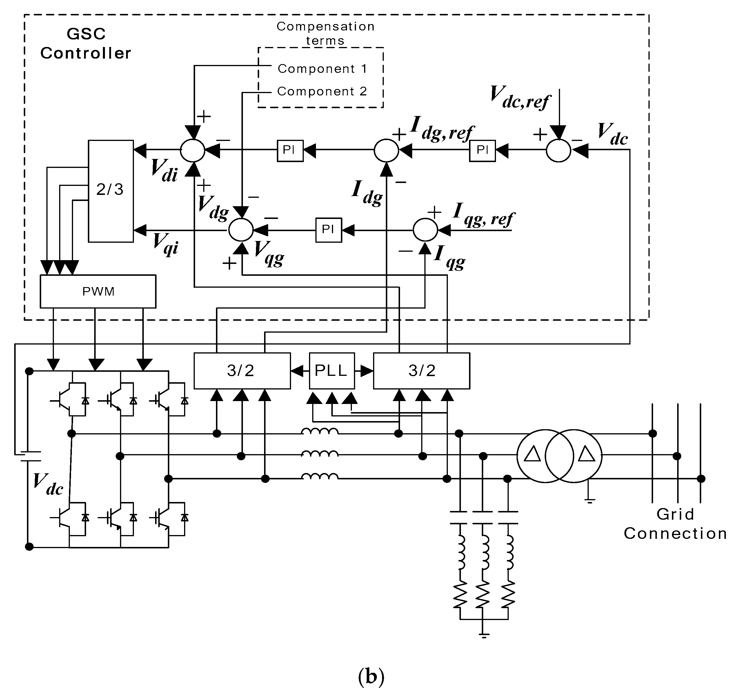
Figure 2.
Maximum power point tracking (MPPT) and de-loaded power extraction curves for different wind speeds.
Figure 2.
Maximum power point tracking (MPPT) and de-loaded power extraction curves for different wind speeds.
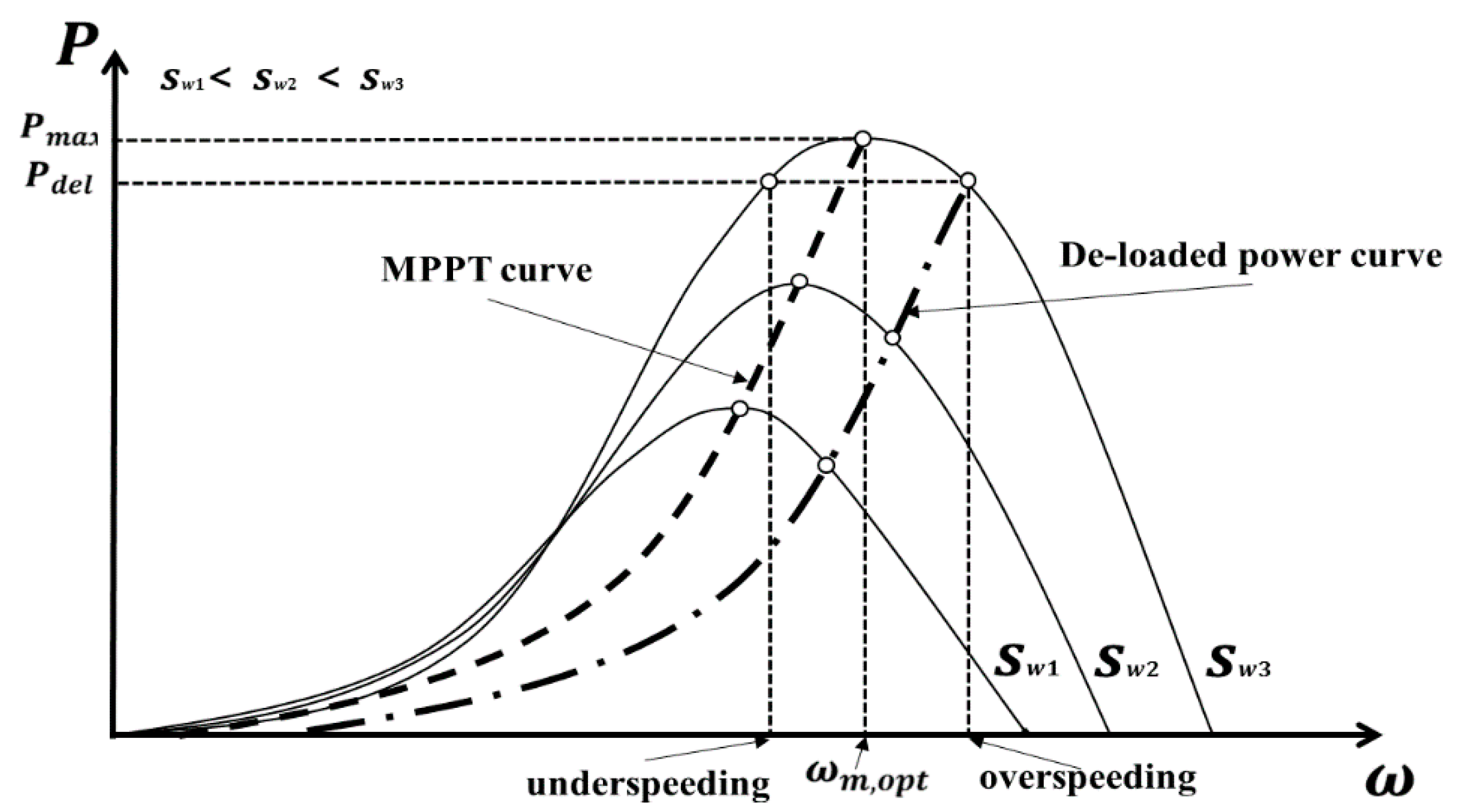
Figure 3.
De-loaded controller.

Figure 4.
KE reserve control scheme.

Figure 5.
KE reserve controller.
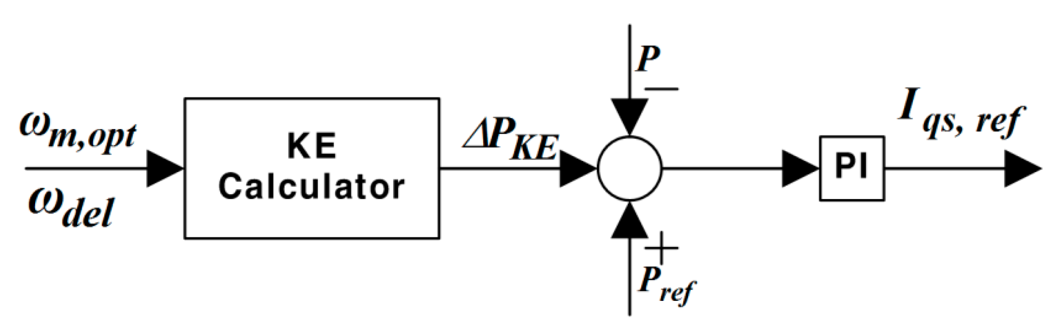
Figure 6.
Pitch angle controller.

Figure 7.
Modified q-axis rotational current control loop.

Figure 8.
The triggering scheme and frequency detection.
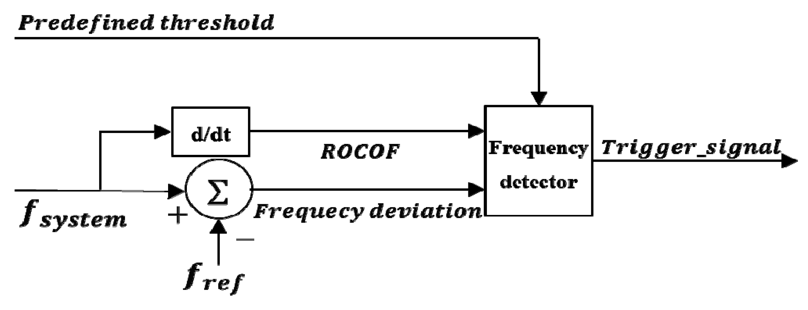
Figure 9.
Proposed optimal strategy scheme.

Figure 10.
Simulated small power system.

Figure 11.
Wind speed variations at each wind farm.

Figure 12.
Active power for individual wind farms in Case 3. (a) WF1; (b) WF2; (c) WF3; (d) WF4; (e) WF5.
Figure 12.
Active power for individual wind farms in Case 3. (a) WF1; (b) WF2; (c) WF3; (d) WF4; (e) WF5.
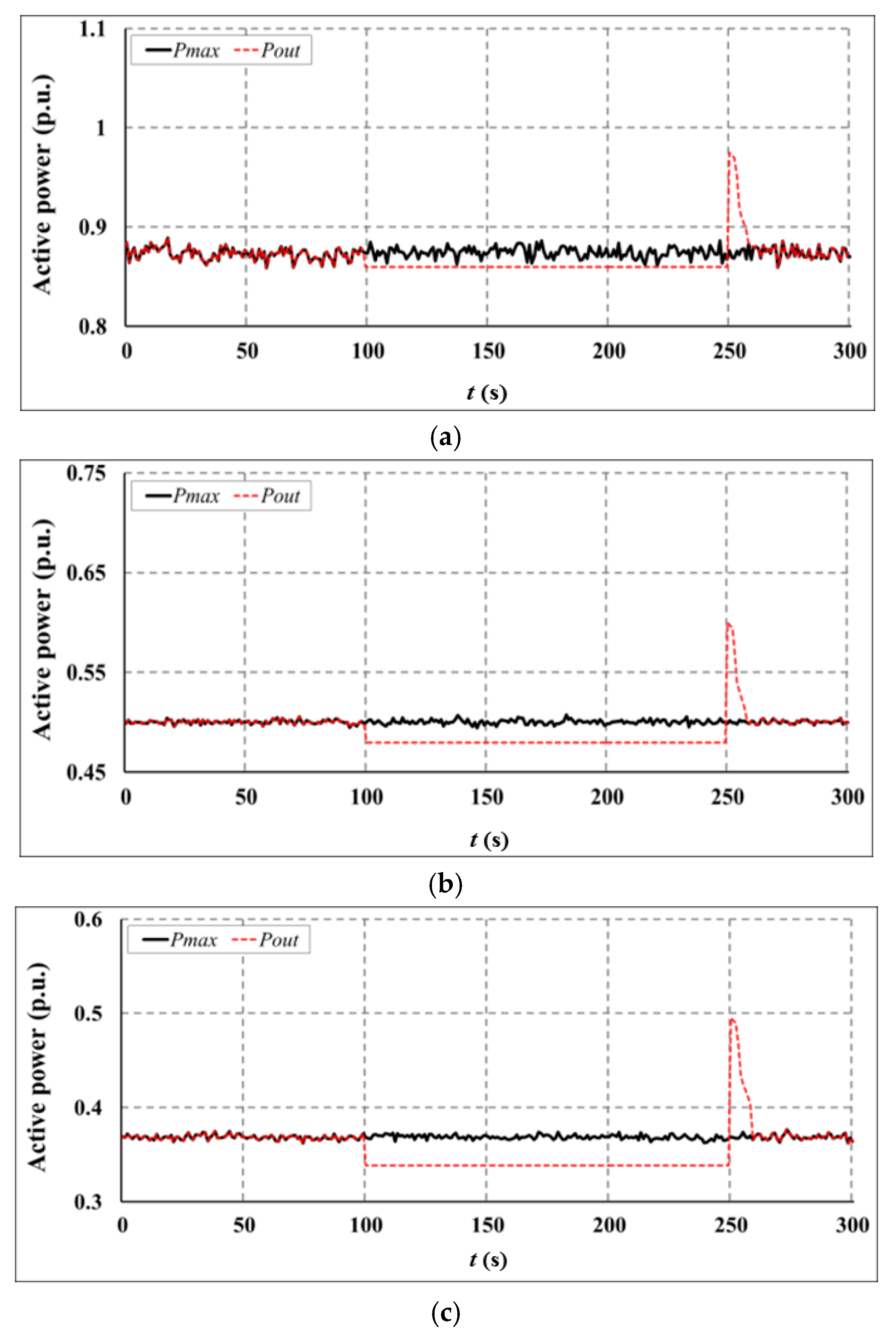
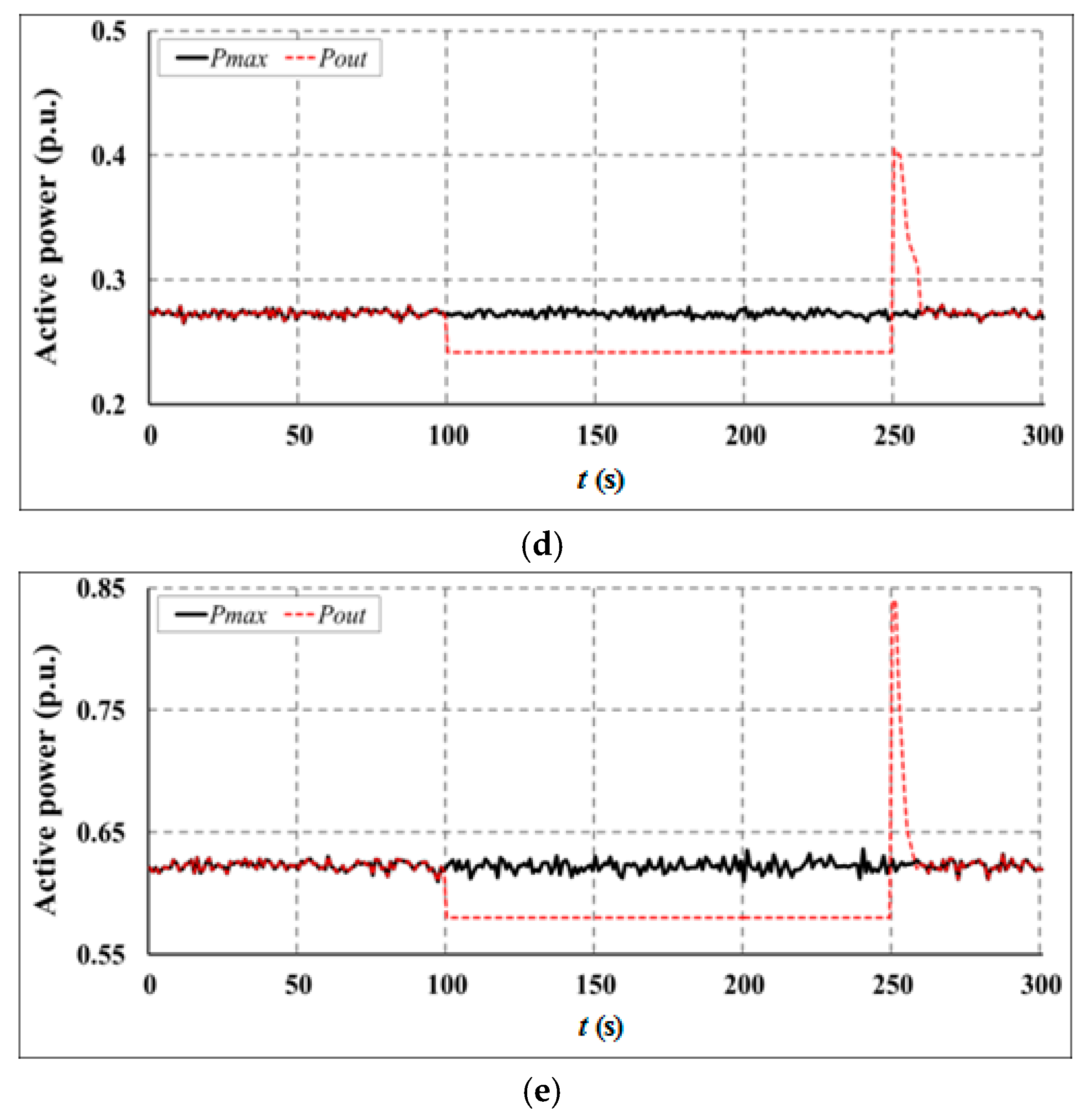
Figure 13.
Rotational speed for individual wind farms in Case 3. (a) WF1; (b) WF2; (c) WF3; (d) WF4; (e) WF5.
Figure 13.
Rotational speed for individual wind farms in Case 3. (a) WF1; (b) WF2; (c) WF3; (d) WF4; (e) WF5.


Figure 14.
Comparison of the system frequency response.
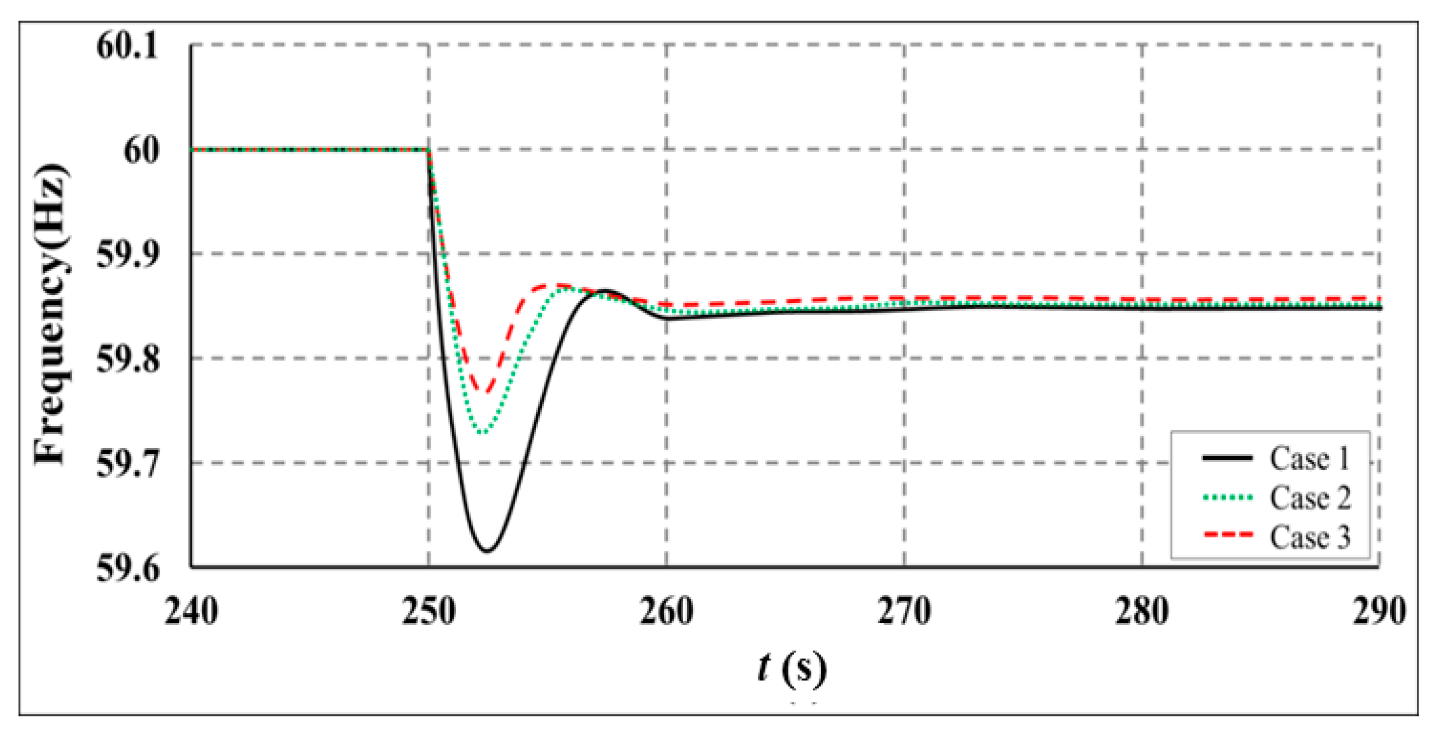
Table 1.
Power output of individual generators.
| Unit | Generator Type | Generation (MW) | Capacity (MW) |
|---|---|---|---|
| G1 | Steam turbine | 80 | 100 |
| G2 | Gas turbine | 40 | 50 |
| G3 | Hydro turbine | 60 | 70 |
| G4 | Hydro turbine | 50 | 60 |
| Total | - | 230 | 280 |
Table 2.
De-loaded power output references for the small power system.
| Wind Farm | Sw (m/s) | ωm,opt (p.u.) | Pmax (MW) | Case 1 (MW) | Case 2 (MW) | Case 3 (MW) |
|---|---|---|---|---|---|---|
| 1 | 11.2 | 1.12 | 13.984 | 13.984 | 13.28 | 13.848 |
| 2 | 9.3 | 0.93 | 8.006 | 8.006 | 7.605 | 7.677 |
| 3 | 8.4 | 0.84 | 5.896 | 5.896 | 5.608 | 5.416 |
| 4 | 7.6 | 0.76 | 4.368 | 4.368 | 4.152 | 3.872 |
| 5 | 10.0 | 1.00 | 9.952 | 9.952 | 9.448 | 9.280 |
| Total | - | - | 42.206 | 42.206 | 40.093 | 40.093 |
Table 3.
Comparison of KE reserves in Case 2 and Case 3.
| Wind Farm | Case 2 | Case 3 | ||
|---|---|---|---|---|
| ωdel (p.u.) | KE (MWs) | ωdel (p.u.) | KE (MWs) | |
| 1 | 1.200 | 8.504 | 1.200 | 8.504 |
| 2 | 1.087 | 14.496 | 1.077 | 13.512 |
| 3 | 0.983 | 11.920 | 1.027 | 15.944 |
| 4 | 0.889 | 9.760 | 0.962 | 15.976 |
| 5 | 1.170 | 16.896 | 1.200 | 20.160 |
| Total | - | 61.576 | - | 74.096 |
© 2017 by the author. Licensee MDPI, Basel, Switzerland. This article is an open access article distributed under the terms and conditions of the Creative Commons Attribution (CC BY) license (http://creativecommons.org/licenses/by/4.0/).
Share and Cite
MDPI and ACS Style
Kim, M.-K. Optimal Control and Operation Strategy for Wind Turbines Contributing to Grid Primary Frequency Regulation. Appl. Sci. 2017, 7, 927. https://doi.org/10.3390/app7090927
AMA Style
Kim M-K. Optimal Control and Operation Strategy for Wind Turbines Contributing to Grid Primary Frequency Regulation. Applied Sciences. 2017; 7(9):927. https://doi.org/10.3390/app7090927
Chicago/Turabian StyleKim, Mun-Kyeom. 2017. "Optimal Control and Operation Strategy for Wind Turbines Contributing to Grid Primary Frequency Regulation" Applied Sciences 7, no. 9: 927. https://doi.org/10.3390/app7090927
Note that from the first issue of 2016, this journal uses article numbers instead of page numbers. See further details here.