Attenuation of Temperature Fluctuations on an External Surface of the Wall by a Phase Change Material-Activated Layer


Department of Environmental Engineering, Lodz University of Technology, ul. Wolczanska 213, 90-924 Lodz, Poland
*
Author to whom correspondence should be addressed.
Appl. Sci. 2018, 8(1), 11; https://doi.org/10.3390/app8010011
Submission received: 29 October 2017
/
Revised: 18 December 2017
/
Accepted: 20 December 2017
/
Published: 22 December 2017
(This article belongs to the Special Issue Phase Change Material (PCM) 2017)
Abstract
:Periodical changes of temperature on an external surface of building envelope, e.g., thermal stress or excessive heat gains, is often an undesirable phenomenon. The idea proposed and described in the following paper is to stabilize the external surface temperature in a period of significant heat gains by the originally developed, novel composite modified by phase change material (PCM) and applied as an external, thin finishing plaster layer. The PCM composite is made from porous, granulated perlite soaked with paraffin wax (Tm = 25 °C) and macro-encapsulated by synthetic resin. The effect of temperature attenuation was estimated for two designated periods of time—the heat gains season (HGS) and the heat losses season (HLS). The attenuation coefficient (AC) was proposed as evaluation parameter of isothermal storage of heat gains determining the reduction of temperature fluctuations. The maximum registered temperature of an external surface for a standard insulation layer was around 20 K higher than for the case modified by PCM. The calculated values of AC were relatively constant during HGS and around two times lower for PCM case. The obtained results confirmed that the proposed modification of an external partition by equipped with additional PCM layer can be effectively used to minimize temperature variations and heat flux in the heat gains season.
1. Introduction
During the last 20 years, phase change materials (PCM), mainly organic or inorganic, became a building fabric or a part of components in many different applications [1]. The most popular organic compounds used in buildings are paraffin. They are characterized by unique thermo-physical properties such as a very high latent heat of phase change with very low volume decrease [2,3]. Additionally, they are non-toxic, non-corrosive, and chemo-physically stable [4]. The weakest feature of paraffin is flammability [5] which limits the possibilities of their application in building interiors [6]. Simultaneously, the inner location of PCM layer is the most effective solution for stabilizing the indoor temperature [7,8]. Particularly, among the passive applications of PCM [9], lightweight construction buildings reveal the highest potential to improve thermal inertia [10]. This effect the storage of a large amount of energy with slight temperature fluctuations in the transition range [11]. Therefore, application of the PCM layer in an inner location was widely investigated [12], taking into account thermal comfort and the energy performance of buildings. Generally, PCM can be implemented into an inner part of a wall structure in different forms such as: impregnation of building materials, micro-encapsulation, or as a shape-stabilized thin plate [13]. Almost any construction material like concrete [14], gypsum [15] and ceramic [16] was considered as a matrix for paraffin or fatty acids. Hawes et al., 1993 [17] examined the performance of gypsum wallboard and concrete block which have been impregnated with PCM. Lee et al. [18] investigated the improvement of thermal performance of residential building walls with a PCM thermal shield. Athienitis [15] studied the thermal performance of a gypsum board impregnated with phase change materials in a building scale. Additionally, improvement of heavyweight, passive solar collector wall was investigated experimentally [19,20] and numerically [21,22].
Although a lot of research studies were dedicated to the investigation of PCM placed from indoor side of the wall the last decade brought a number of different external applications. One of the first ideas was to use PCM in shading systems like blinds, e.g., a louver system [23]. In such systems, the energy from solar radiation is stored during the period of excessive heat gains (during a day) and released at night [24]. Such solution can not only balance the heat flux through glazing facades effectively, but also prevents overheating during peak hours as well. Alternatively, PCM can be applied directly to the glazing unit as a filling for an air gap between glass sheets [25] or as a glass block [26], giving a similar effect as blinds. However, recent reports [27] have shown that PCM affects not only the direct transmission of solar energy, but also can improve the energy performance of opaque, well-insulated walls [28] or roofs [29]. In opaque structures, PCM was used to stabilize the temperature of photovoltaic (PV) panels and increase their effectiveness [30]. Such a solution can be attractive for any PV system integrated with building envelope, e.g., building facades (BIPV) characterized by a limited capability to cool down covering elements exposed to solar radiation [31].
The main purpose of this work is to experimentally investigate the effect of external, thin PCM layers on the dynamics of the thermal insulation and the overall performance of the external wall. The full scale experiment was conducted under moderate climatic conditions over the whole calendar year. This main goal was formulated according to the Kosny J. hypothesis, that as a result of the improved thermal performance gained from PCM incorporation, lighter and thinner building envelopes can be designed and constructed to take full advantage of performance [11].
2. Problem Definition and Research Challenge
As it was stated in Section 1, the application of PCM in external layers of building envelope becomes more and more popular and attractive solution. One of the first works dedicated to find the optimal location of PCM layer in an external building wall was done experimentally by Jin et al. in 2013 [32]. Authors evaluated and compared thermal performance of building walls with and without PCM. It was concluded that the optimal location of a PCM layer is approximately 1/5 of a wall thickness from the internal surface. Similar analysis of position of macro-encapsulated PCM in concrete walls was investigated in [14]. The authors considered only three possible positions: the inner part, outer part, and the middle of the wall. They found out by experimental investigations that on sunny days, the maximum and minimum temperatures of the case externally bonded with PCM were respectively 2.0–2.5 K lower, and 0.5–1.5 K higher when compared with those of the reference model without PCM. This solution is advantageous to applications in buildings where PCM walls can be used to absorb heat during daytime and release it at night, or when there are no internal heat sources. Similar results were achieved by Panayiotou et al. [33] who revealed more than 28% of energy savings by the location of a PCM layer at an optimum position in the external wall between the outer side of the brick and the plaster layer. The other parametric study of PCM location was done using computational techniques [27]. Authors revealed that the outer location of a latent heat storage layer could considerably improve thermal performance in summer. For cold climate applications, the recommendations based on numerical simulations were formulated in [34].
The effect of an externally positioned PCM layer is much higher when the material is combined with thermal insulation. Initial studies and reports on the enhancement of insulation layer were performed based on the investigation of the effect of microencapsulated PCM dispersed in a cellulose insulation [29]. The material was applied in an attic floor and dynamic thermal characteristics were analyzed numerically. Using a refined computational model, the effect of the external PCM layer in a wall was investigated by Wieprzkowicz & Heim in 2016 [28]. In the paper [35], a novel way for testing various kinds of wall constructions, known as plug-and-play walls (PPW), was introduced. The use of the PPW concept was demonstrated by evaluating the thermal performance of a thin PCM layer, herein referred as “PCM thermal board” (PCMTB). The results showed that the average daily heat transfer reduction, was 27.4% and 10.5% for south- and west-directed walls respectively. Additionally, the average heat flux reductions when the heat fluxes of the control walls were at their peaks were 67.0% and 80.2% for the same façade orientations, respectively. It was demonstrated that the integration of a thin PCM layer also delayed the peak heat transfer rate per unit of a wall area approximately from two to three hours. Therefore, this solution was classified by some authors as a new building technology towards dynamic thermal insulation [36,37].
The concept proposed and developed in this paper concerns the case where the PCM layer is located on the external surface of thermal insulation exposed to the external environment. The PCM composite was optimized for summer conditions to decrease the heat gain flux and to reduce overheating risks in the room. Authors assumed that PCM layer stabilized external surface temperature not only during the day (storage period), but also during the night (releasing period). For long term exploitation, it would lead to balancing of heat transfer through the wall during the whole summer season and would generally improve the thermal performance of the wall.
3. Walls with an Activated, External Surface Layer
One of the main objectives of this research work was to develop a novel composite by using extremely porous granulated perlite (as a matrix), paraffin wax (as a PCM), and a quick-drying flexible liquid membrane (as a sealing material). The composite differs from existing solutions based on cellulose insulation [36] or polyurethane foam matrix [38], where PCM was initially microencapsulated. The challenge of a development such as the composite was to ensure the tightness of the structure when the material became liquid. Therefore, the production of composite layer had to be performed using the following steps. Firstly, perlite with a specified particle size was soaked with liquid PCM (melting temperature Tm = 25 °C). Then the whole structure was cooled down and mixed with the sealing material. The composite was implemented on the external surface of the insulation material—the mineral wool (Figure 1). The mineral wool sample was prepared to be used directly in an experimental wall, developed for the purpose of this experiment. The component was conditioned with a stable temperature (below Tm) for 12 h to achieve a fully dried state. After that, the tightness was checked by testing it during the next three weeks by direct exposition to solar radiation in the day (material temperature above melting temperature) and cooling in the night. The final insulation component with additional layers of PCM-perlite composite was installed in the wall structure and equipped with temperature sensors.
The overall thickness of the PCM-perlite composite was 2 cm, and the total density was 694 kg/m3. 1 kg of fresh composite slurry was produced from 0.125 kg of perlite, 0.125 kg of paraffin wax and 0.75 kg of liquid membrane. The composite material was integrated with the mineral wool directly by liquid membrane. Not any other binder or finishing material was used.
4. Experimental Set-Up
In order to investigate the thermal performance of the developed PCM-perlite composite integrated with thermal insulation under moderate climatic conditions (the city of Lodz, 51°46 N & 19°27 E, Poland, Central Europe), a special experimental set up was constructed. The main assumption was to build a test stand that would allow to take into account all thermal processes and disturbances occurring in a real environment for which the proposed solution was designed. For this purpose, part of the existing building external wall was reconstructed. Since the thermal performance of the external partition is strongly influenced by both internal and external heat fluxes, it was assumed that experimental set-up should include not only the considered wall, but also an adjacent room.
The proposed PCM-perlite composite was designed mainly with modern, lightweight constructed office buildings in mind. Thus, the experimental wall was constructed as steel framework with a ventilated rain screen wall, and covered with BIPV panels from outside with a centrally positioned square window. The area around the window was divided into test sections with dimensions 60 cm × 60 cm (Figure 2).
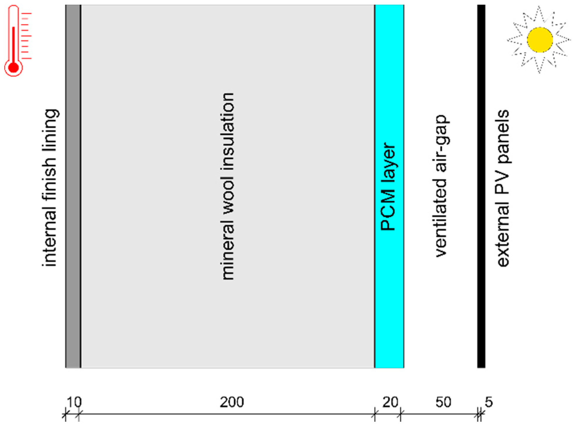
Such an approach was taken to conduct simultaneous doubled tests of developed composite and reference, basic constructions (a mineral wool without PCM). It was assumed that evaluation of the proposed solution should be made by comparison to the reference case. The basic external wall was built from the following layers (pointed from inside): 1 cm of chipboard, 20 cm of mineral wool, 5 cm of ventilated air gap, and external lining made from a copper indium selenide (CIS) PV panel. The modified wall differed from the insulation layer, which was covered from the outside with an additional, thermally active composite (PCM-perlite), Figure 3.
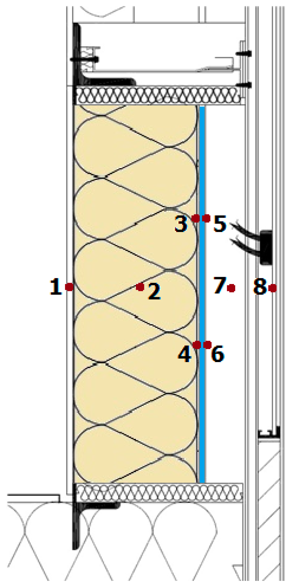
Each tested section of the experimental wall was equipped with eight temperature sensors (Figure 3). The first one measured the temperature on the internal surface of the wall, which can be treated as an internal boundary conditions for the mineral wool. The second one was placed in the middle of the thermal insulation layer and was installed to check the influence of the PCM-perlite composite on the thermal response of the insulation. The next four sensors were concentrated around the PCM-perlite layer. Such compaction of the sensors was introduced in order to increase the accuracy of the measurements and for mutual verification. Since latent heat storage is an isothermal process, accurate readouts are crucial for robust analysis of PCM performance. The last two temperature sensors were installed in the ventilation cavity and on the back side of the PV panels. These were used for the verification of compatibility of external boundary conditions for all sections.
The digital temperature sensors, which have a high precision bandgap reference with a proportional-to-absolute-temperature (PTAT) output and a low-power and high-precision analog to digital converter (ADC), were used. The temperature sensors were fully calibrated. Two types of sensors were used (Figure 4): TSic 506 (sensors 1–6) and TSic 306 (sensors 7 and 8). It was stated that due to the high thermal resistance of the insulation layer and thus small temperature fluctuations, very high accuracy was required to precisely compare the results. High accuracy of the measured values was also required to the describe performance of the PCM-perlite layer, which is very sensitive to temperature fluctuations. According to this, the most accurate sensors, with an accuracy of ±0.1 K in a range of 40 K (from 5 to 45 °C), were applied (Table 1). Due to the fact that the measurement range of this sensor is −10 to 60 °C, it could not be used for the measurement in the places numbered 7 and 8 (Figure 4), since temperature in these locations could exceed this range. For the measurement of air temperature in the cavity and on the back surface of PV panels, sensors with a lower accuracy (of ±0.3 K in a range from 10 to 90 °C) but wider measurement range (−50 to 150 °C) were applied. Moreover, a middleware electronic board with an advanced RISC machine (ARM) microprocessor that communicates the sensors, and a raspberry pi device, was custom-developed for the purpose of the experimental set-up. Software for this purpose was developed in C/C++ and Python using GPL licensed compilers and libraries. The provided solution automated the process of periodical collecting data from the sensors and enabled reliable and secure data storage. The readouts were made with a 5-min time step.
The thermal conditions inside the adjacent room reflected the indoor climate of a typical office. Moreover, external environment parameters such as dry bulb temperature, and direct and diffuse solar radiation were monitored by the weather station located on the roof above the experimental set-up. This allowed to verification for any incorrect readouts not consistent with the external boundary conditions that were made.
5. Results, Analysis, and Discussion
5.1. External Boundary Conditions
Due to air flow in the façade (induced by wind) it was also crucial to verify the temperature distribution in the ventilated cavity. Reliable comparison of the results obtained for two sections of experimental set-up could be made only when external boundary conditions (due to temperature in the air gaps) were unified. Based on the results presented in Figure 5, it was observed that the temperature next to the section with PCM-perlite composite was convergent with the temperature next to the reference section. This was also confirmed by the value of determination coefficient (R2 = 0.99) calculated for the whole analyzed period of one calendar year.
5.2. Temperature Fluctuations
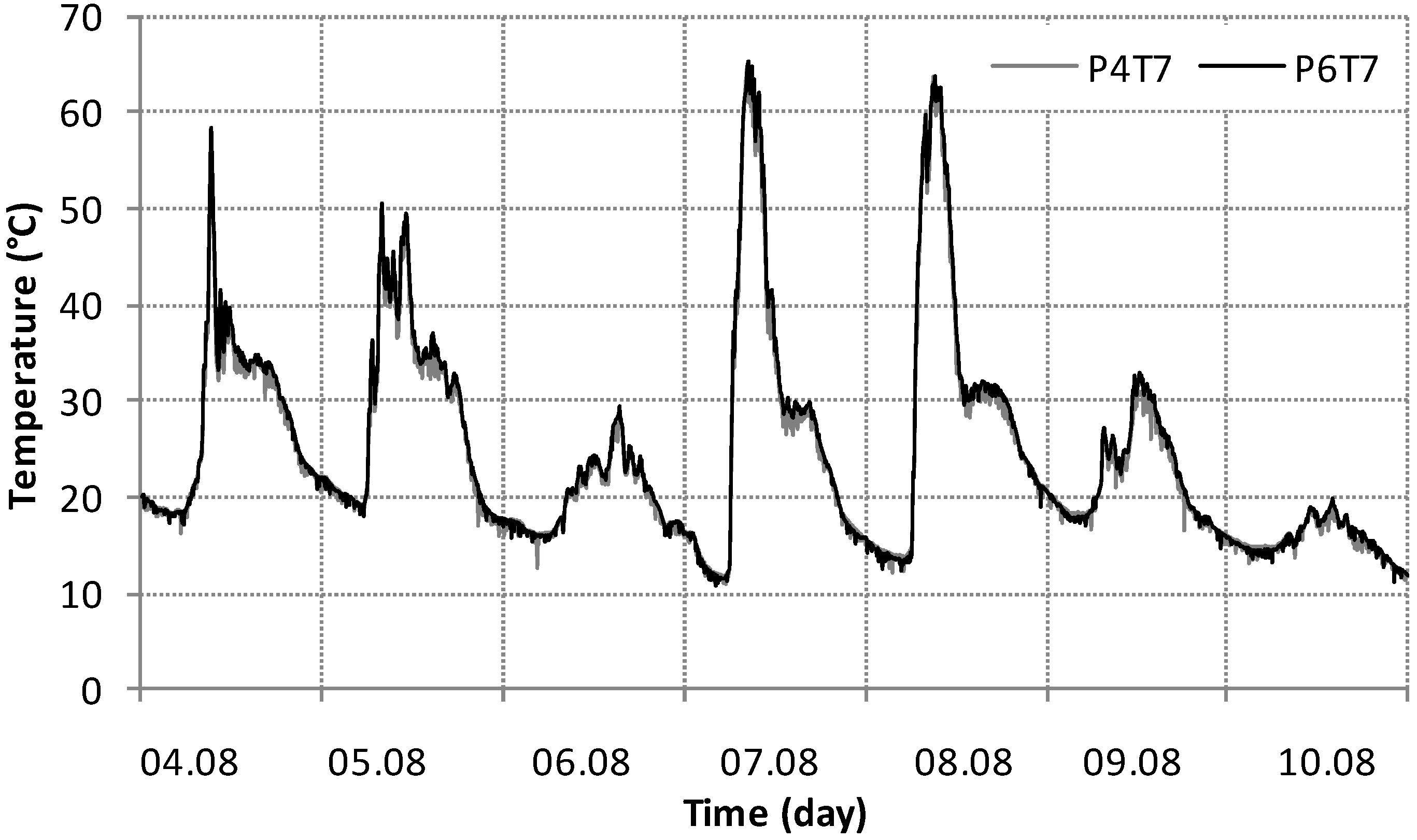
Due to a large number of measured data, temperature fluctuations in selected sections were presented only for a specific period of time—one week. Temperature distributions on the external surface of the components were presented in Figure 6. Nevertheless, all results collected during one year of measurements were comprehensively analyzed and conclusions stated below were justified.
In Figure 6, temperature fluctuations for two sections: the enhanced with PCM-perlite (P4) and the reference panel (P6), were presented. Based on the results presented in Figure 6 it was observed that temperature on the external surface of panels modified by the PCM-composite was visibly lower during the day and higher during the night-time, compared to the reference panel. As expected, application of PCM reduced daily amplitudes of the external surface temperature. It was also observed that due to the highly intense and sudden occurrence of solar radiation during latent heat accumulation in PCM-composite temperature rose, but did so more slowly than the reference panel. Moreover, when the temperature dropped below the solidification temperature of paraffin, release of accumulated heat caused a very slow decrease of temperature.
To compare both cases (PCM and reference) the degree hours (DH) related to the average temperature (Tav) for reference panel were calculated.
where
- n—number of readouts during a one-year measurement (n = 105,120),
- 1/12—coefficient due to 5-min time step of measurement readout,
- Ti,x—surface temperature, x denotes specific test section (PCM/REF).
Values of DH are the measure of temperature fluctuations and were calculated as an absolute value of temperature during an analyzed period of time. It means that the periods of heat accumulation and releasing were summed up. Calculated DH are displayed in Figure 6. The values obtained for the reference (REF) case were almost two times higher than for the PCM case. These results confirmed the two times lower dynamics of the wall with a PCM layer in comparison with a traditionally insulated partition.
5.3. Attenuation Coefficient
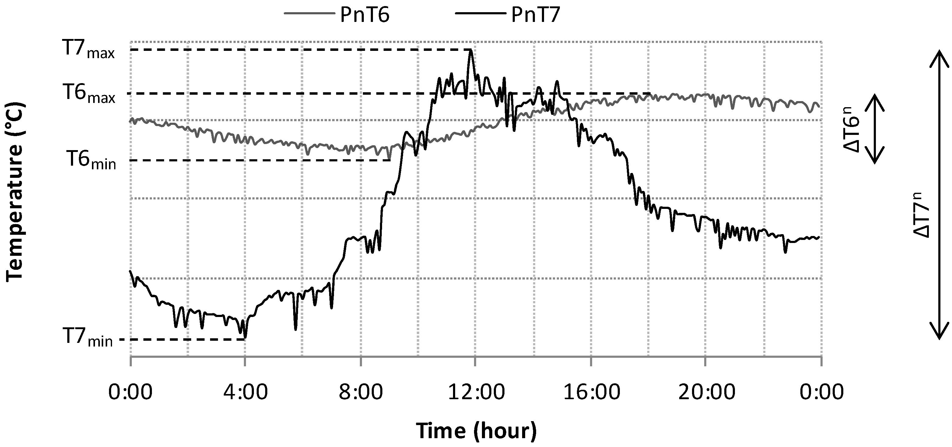
According to the literature [39,40], the thermal stability of a building envelope can be typically characterized by the decrement factor. Since the fluctuations of outdoor air temperature are the cause of fluctuations in the temperature of the building envelope, the decrement factor is calculated as the ratio of amplitude of external temperature fluctuations to internal surface temperature fluctuations. In most theoretical considerations, it is assumed that temperature fluctuations are harmonic, i.e., they follow the sine wave within a 24 h period. For the purpose of this study—analysis of the external active layer performance, the attenuation coefficient was proposed, as (Figure 7):
where:
The attenuation coefficient (AC) was introduced to quantitatively describe and compare the ability of an externally positioned layer of material to attenuate the temperature fluctuations on the external boundary of the partition. Considering a single day of the analysis, it can be stated that the higher value of attenuation coefficient causes the bigger daily temperature amplitude on an external surface. Comparing results for analyzed sections, it can be concluded that lower values of attenuation coefficient means a greater ability of the layer to decrease the temperature fluctuations.
The analyzed one-year period of measurement was divided into two seasons:
- Heat loss season (HLS)—days when maximum daily temperature on external surface of the wall was higher than maximum daily temperature in the ventilated cavity of the facade,
- Heat gain season (HGS)—days when maximum daily temperature on external surface of the wall was lower than maximum daily temperature in the ventilated cavity of the facade.
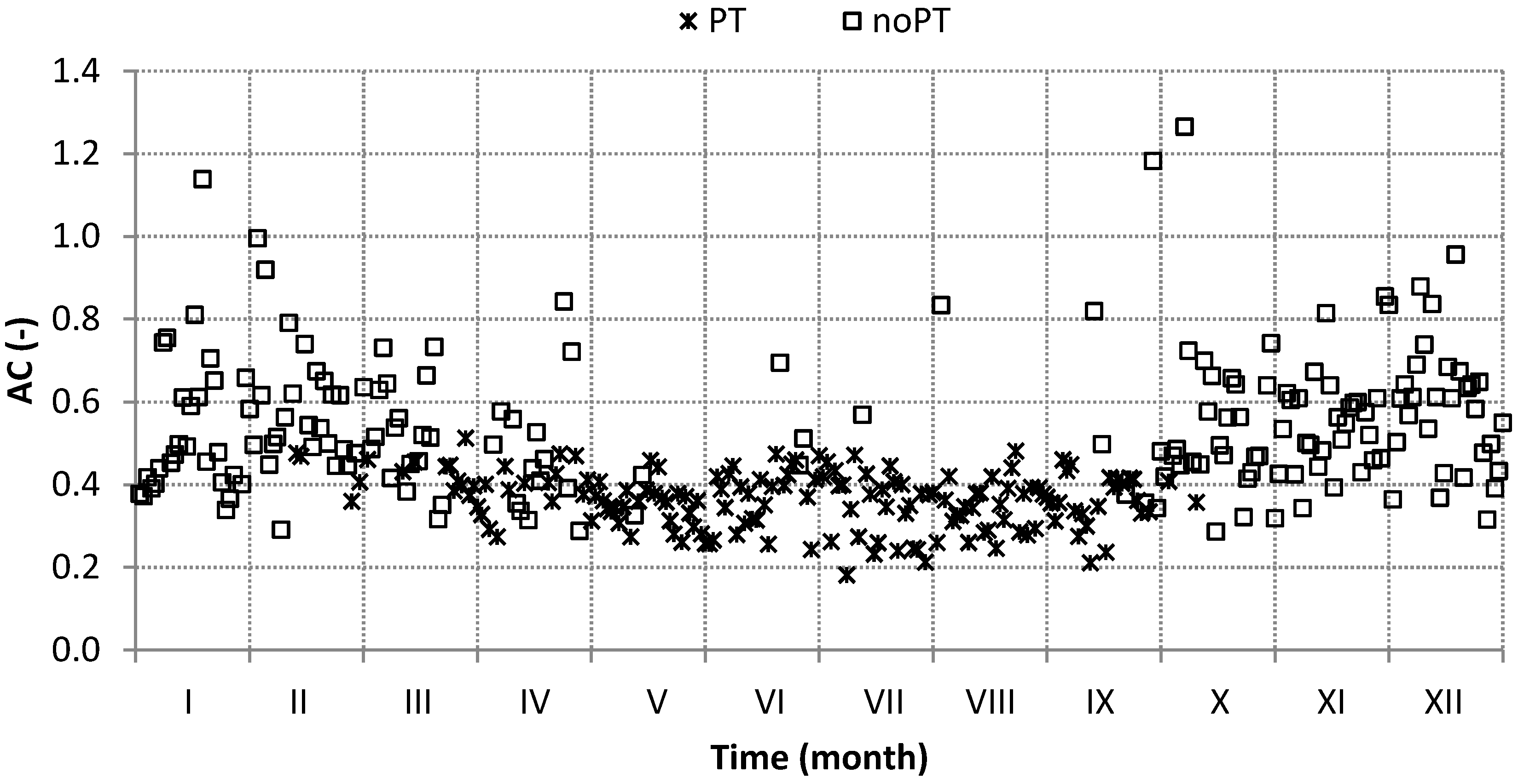
Values of attenuation coefficients were calculated for each day of the analyzed one-year period of time. Nevertheless, since the aim of comparative analysis was to determine the effect of latent heat storage on thermal performance of the wall, it was stated that analysis should be proceeded only for the days when phase change occurred in the PCM-perlite composite (P4). It was assumed that latent heat accumulation could have occurred when maximum daily temperature measured in the point T7 (Figure 4) was greater than 25 °C, and minimum daily temperature measured in the point T4 was lower than 25 °C. In Figure 8, the values of AC calculated for the period of the whole year for the test section (P4) were presented. It can be observed that during the winter months (X-II) phase change did not occur, and due to the assumption of HLS length, only HGS was further analyzed (164 days from 352).
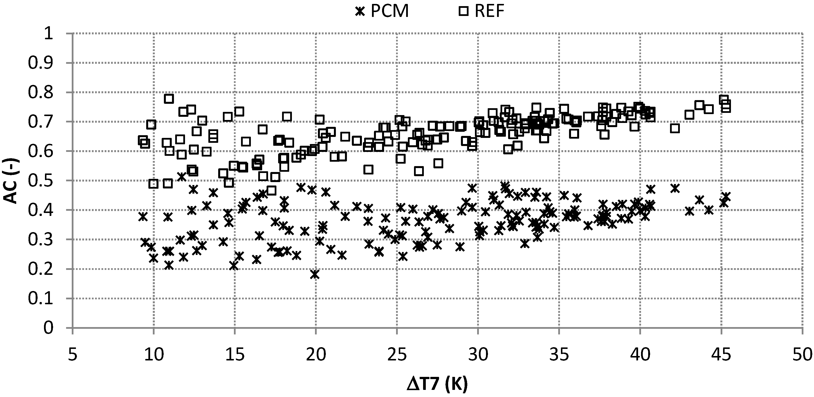
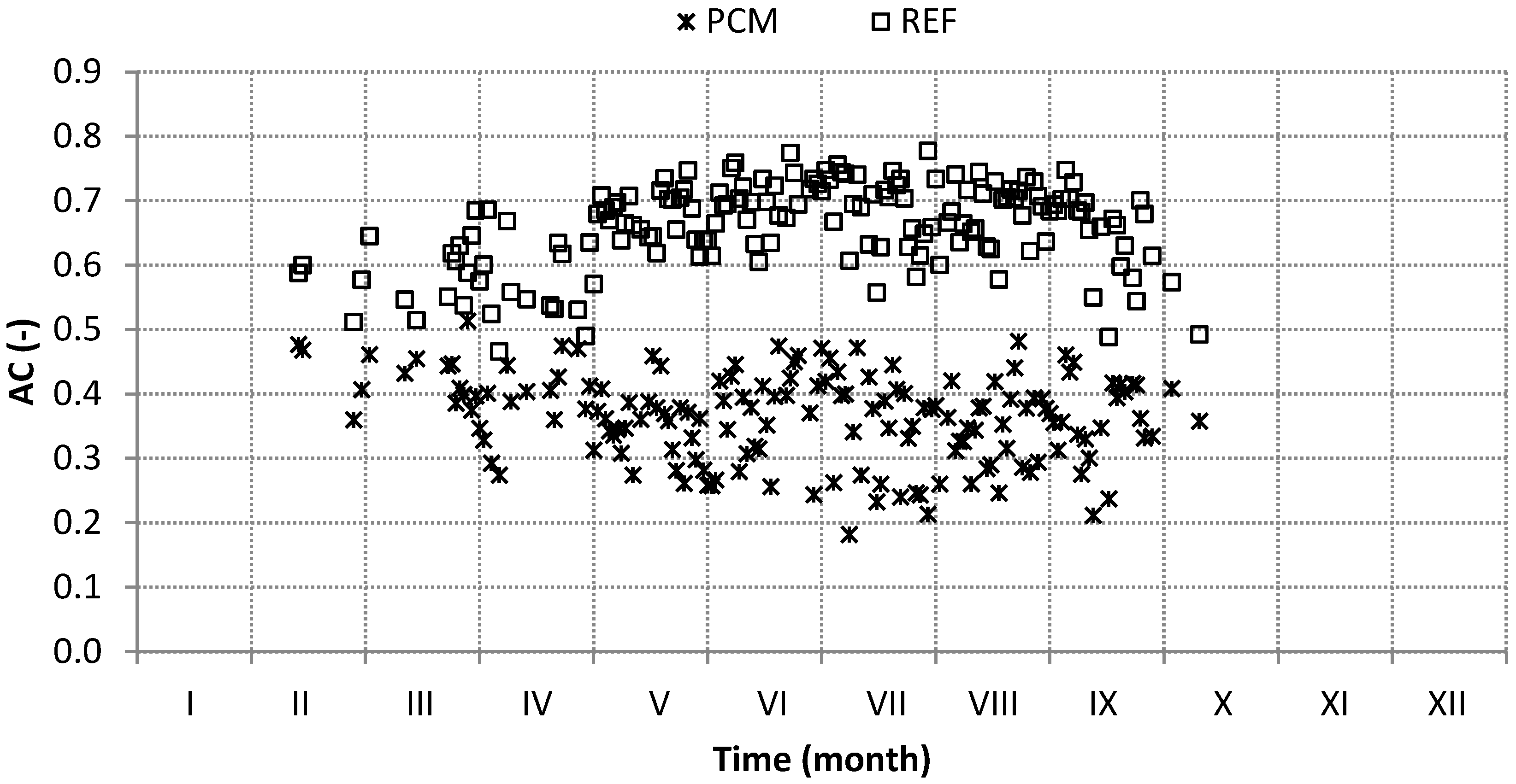
Results obtained for the panels with PCM-perlite composite (P4) and reference one (P6) are presented in Figure 9. In the further analysis values measured by two sensors—T6 and T7 were used. As was proved before, temperatures registered by sensor T7 were almost equal for all sections; thus the differences revealed in attenuation coefficient came from the different temperatures registered on the external surface of the wall.
Based on the results presented in Figure 9 it can be clearly noticed that the values of AC calculated for the reference test section (P6 = REF) are much higher than for PCM-perlite composite (P4 = PCM). The mean value obtained for P4 was almost two-fold lower than for P6 (0.36 and 0.66 respectively). Moreover, it was observed that the standard deviations from the average values of AC were similar for both cases (0.068 and 0.067).
The biggest differences between two analyzed test sections were noticed during the summer months (V–VIII). Analysis of the correlation between AC and daily temperature difference in the ventilation cavity (Figure 10) revealed that for lower daily external temperature attenuations (up to 20 K), values of AC were more differentiated, while with the increase of ΔT7, their values became more convergent. It can be also noted that maximum AC for both cases was independent of temperature alterations. On the other side, the minimum values of AC rose for higher values of ΔT7.
6. Conclusions
The concept of external application of PCM layer in the building wall was presented in the paper. The general idea of this solution was to attenuate the daily temperature fluctuations on the external wall surface. Theoretically, the effect could be obtained by charging the phase change material during the day and releasing stored energy during the night. This assumption was based on preliminary, theoretical analyses conducted by authors and others, referred in Section 2.
Based on the experiments conducted during one year of measurements it was found out that transition occurred only during some specific days. This was caused not only by the assumed melting temperature of the PCM-composite, but also by daily external temperature fluctuations. For fluctuations below 20 K, the PCM application contributed to the attenuation of temperature fluctuations of the external surface of the wall, but the efficiency of this attenuation was variable. The behavior was more regular for higher daily temperature differences.
The assessment of PCM-composite performance and its comparison with the reference case was performed based on the Attenuation Coefficient (AC). The AC was calculated using the formula proposed by authors (when temperature fluctuations are enharmonic) as an alternative to well-known decrement factor. This original approach allowed the assessment of experimental results obtained under unstable and unpredictable changes of climatic conditions. The obtained values of AC showed that PCM-composites revealed around two times higher heat storage potential in comparison with traditional, high-density mineral wool. On the other hand, this effect strongly depended on external daily temperature fluctuations related to assumed melting temperature of PCM.
For some, particular building applications under specific climatic conditions the stabilization of heat flux waves amplitude can lead to decreasing of heat loss and gains as well as building energy requirements for heating or cooling. The possible energy savings were not considered in that paper, but could be studied in the future works.
Acknowledgments
This work was partly funded by The National Centre for Research and Development as part of the project entitled: ‘Promoting Sustainable Approaches towards Energy Efficiency in Buildings as Tools Towards Climate Protection in German and Polish Cities: Developing facade technology for zero-emission buildings’ {acronym: GPEE, project number: WPN/5/2013 (01RS1201A)}.
Author Contributions
Dariusz Heim formulated the research problem and tasks; Dariusz Heim and Anna Wieprzkowicz conceived and designed the experiments; Anna Wieprzkowicz built the experimental set-up, performed the experiments and collected data; Dariusz Heim and Anna Wieprzkowicz analyzed the data and wrote the paper.
Conflicts of Interest
The authors declare no conflict of interest. The founding sponsors had no role in the design of the study; in the collection, analyses, or interpretation of data; in the writing of the manuscript, and in the decision to publish the results.
References
- Mehling, H.; Cabeza, L.F. Heat and Cold Storage with PCM: An up to Date Introduction into Basics and Applications; Springer: Berlin, Germany, 2008; ISBN 354068557X. [Google Scholar]
- Khudhair, A.M.; Farid, M.M. A review on energy conservation in building applications with thermal storage by latent heat using phase change materials. Energy Convers. Manag. 2004, 45, 263–275. [Google Scholar] [CrossRef]
- Zalba, B.; Marín, J.M.; Cabeza, L.F.; Mehling, H. Review on thermal energy storage with phase change: Materials, heat transfer analysis and applications. Appl. Therm. Eng. 2003, 23, 251–283. [Google Scholar] [CrossRef]
- Cabeza, L.F.; Castell, A.; Barreneche, C.; De Gracia, A.; Fernández, A.I. Materials used as PCM in thermal energy storage in buildings: A review. Renew. Sustain. Energy Rev. 2011, 15, 1675–1695. [Google Scholar] [CrossRef]
- Mclaggan, M.S.; Hadden, R.M.; Gillie, M. Flammability assessment of phase change material wall lining and insulation materials with different weight fractions. Energy Build. 2017, 153, 439–447. [Google Scholar] [CrossRef]
- Serrano, S.; Barreneche, C.; Navarro, A.; Haurie, L.; Fernandez, A.I.; Cabeza, L.F. Use of multi-layered PCM gypsums to improve fire response. Physical, thermal and mechanical characterization. Energy Build. 2016, 127, 1–9. [Google Scholar] [CrossRef]
- Zastawna-Rumin, A.; Nowak, K. Experimental research of a partition composed of two layers of different types of PCM. Energy Procedia 2016, 91, 259–268. [Google Scholar] [CrossRef]
- Evola, G.; Marletta, L.; Sicurella, F. Simulation of a ventilated cavity to enhance the effectiveness of PCM wallboards for summer thermal comfort in buildings. Energy Build. 2014, 70, 480–489. [Google Scholar] [CrossRef]
- Soares, N.; Costa, J.J.; Gaspar, A.R.; Santos, P. Review of passive PCM latent heat thermal energy storage systems towards buildings’ energy efficiency. Energy Build. 2013, 59, 82–103. [Google Scholar] [CrossRef]
- Ahmad, M.; Bontemps, A.; Sallée, H.; Quenard, D. Thermal testing and numerical simulation of a prototype cell using light wallboards coupling vacuum isolation panels and phase change material. Energy Build. 2006, 38, 673–681. [Google Scholar] [CrossRef]
- Kośny, J. Chapter 2: Short history of PCM applications in building envelopes. In PCM-Enhanced Building Components; Springer: Berlin, Germany, 2015; p. 281. ISBN 9783319142852. [Google Scholar]
- Tyagi, V.V.; Buddhi, D. PCM thermal storage in buildings: A state of art. Renew. Sustain. Energy Rev. 2007, 11, 1146–1166. [Google Scholar] [CrossRef]
- Kuznik, F.; David, D.; Johannes, K.; Roux, J.J. A review on phase change materials integrated in building walls. Renew. Sustain. Energy Rev. 2011, 15, 379–391. [Google Scholar] [CrossRef]
- Shi, X.; Memon, S.A.; Tang, W.; Cui, H.; Xing, F. Experimental assessment of position of macro encapsulated phase change material in concrete walls on indoor temperatures and humidity levels. Energy Build. 2014, 71, 80–87. [Google Scholar] [CrossRef]
- Athienitis, A.K.; Liu, C.; Hawes, D.; Banu, D.; Feldman, D. Investigation of the thermal performance of a passive solar test-room with wall latent heat storage. Build. Environ. 1997, 32, 405–410. [Google Scholar] [CrossRef]
- Vicente, R.; Silva, T. Brick masonry walls with PCM macrocapsules: An experimental approach. Appl. Therm. Eng. 2014, 67, 24–34. [Google Scholar] [CrossRef]
- Hawes, D.W.; Feldman, D.; Banu, D. Latent heat storage in building materials. Energy Build. 1993, 20, 77–86. [Google Scholar] [CrossRef]
- Lee, K.O.; Medina, M.A.; Raith, E.; Sun, X. Assessing the integration of a thin phase change material (PCM) layer in a residential building wall for heat transfer reduction and management. Appl. Energy 2015, 137, 699–706. [Google Scholar] [CrossRef]
- Kara, Y.A.; Kurnuç, A. Performance of coupled novel triple glass unit and PCM wall. Appl. Therm. Eng. 2012, 35, 243–246. [Google Scholar] [CrossRef]
- Sun, D.; Wang, L. Research on heat transfer performance of passive solar collector-storage wall system with phase change materials. Energy Build. 2016, 119, 183–188. [Google Scholar] [CrossRef]
- Ghoneim, A.A.; Klein, S.A.; Duffie, J.A. Analysis of collector-storage building walls using phase-change materials. Sol. Energy 1991, 47, 237–242. [Google Scholar] [CrossRef]
- Heim, D. Isothermal storage of solar energy in building construction. Renew. Energy 2010, 35, 788–796. [Google Scholar] [CrossRef]
- Silva, T.; Vicente, R.; Rodrigues, F. Literature review on the use of phase change materials in glazing and shading solutions. Renew. Sustain. Energy Rev. 2016, 53, 515–535. [Google Scholar] [CrossRef]
- Bianco, L.; Vigna, I.; Serra, V. Energy assessment of a novel dynamic PCMs based solar shading: Results from an experimental campaign. Energy Build. 2017, 150, 608–624. [Google Scholar] [CrossRef]
- Goia, F.; Perino, M.; Serra, V. Experimental analysis of the energy performance of a full-scale PCM glazing prototype. Sol. Energy 2014, 100, 217–233. [Google Scholar] [CrossRef]
- Fokaides, P.A.; Kylili, A.; Kalogirou, S.A. Phase change materials (PCMs) integrated into transparent building elements: A review. Mater. Renew. Sustain. Energy 2015, 4, 6. [Google Scholar] [CrossRef]
- Heim, D.; Wieprzkowicz, A. Positioning of an isothermal heat storage layer in a building wall exposed to the external environment. J. Build. Perform. Simul. 2016, 9, 542–554. [Google Scholar] [CrossRef]
- Wieprzkowicz, A.; Heim, D. Energy performance of dynamic thermal insulation built in the experimental façade system. Manag. Environ. Qual. 2016, 27. [Google Scholar] [CrossRef]
- Kosny, J.; Fallahi, A.; Shukla, N.; Kossecka, E.; Ahbari, R. Thermal load mitigation and passive cooling in residential attics containing PCM-enhanced insulations. Sol. Energy 2014, 108, 164–177. [Google Scholar] [CrossRef]
- Islam, M.M.; Pandey, A.K.; Hasanuzzaman, M.; Rahim, N.A. Recent progresses and achievements in photovoltaic-phase change material technology: A review with special treatment on photovoltaic thermal-phase change material systems. Energy Convers. Manag. 2016, 126, 177–204. [Google Scholar] [CrossRef]
- Machniewicz, A.; Knera, D.; Heim, D. Effect of transition temperature on efficiency of PV/PCM panels. Energy Procedia 2015, 78, 1684–1689. [Google Scholar] [CrossRef]
- Jin, X.; Medina, M.A.; Zhang, X. On the importance of the location of PCMs in building walls for enhanced thermal performance. Appl. Energy 2013, 106, 72–78. [Google Scholar] [CrossRef]
- Panayiotou, G.P.; Kalogirou, S.A.; Tassou, S.A. Evaluation of the application of Phase Change Materials (PCM) on the envelope of a typical dwelling in the Mediterranean region. Renew. Energy 2016, 97, 24–32. [Google Scholar] [CrossRef]
- Chwieduk, D.A. Dynamics of external wall structures with a PCM (phase change materials) in high latitude countries. Energy 2013, 59, 301–313. [Google Scholar] [CrossRef]
- Lee, K.O.; Medina, M.A.; Sun, X. On the use of plug-and-play walls (PPW) for evaluating thermal enhancement technologies for building enclosures: Evaluation of a thin phase change material (PCM) layer. Energy Build. 2015, 86, 86–92. [Google Scholar] [CrossRef]
- Hoes, P.; Hensen, J.L.M. The potential of lightweight low-energy houses with hybrid adaptable thermal storage: Comparing the performance of promising concepts. Energy Build. 2016, 110, 79–93. [Google Scholar] [CrossRef]
- Aditya, L.; Mahlia, T.M.I.; Rismanchi, B.; Ng, H.M.; Hasan, M.H.; Metselaar, H.S.C.; Muraza, O.; Aditiya, H.B. A review on insulation materials for energy conservation in buildings. Renew. Sustain. Energy Rev. 2017, 73, 1352–1365. [Google Scholar] [CrossRef]
- Amaral, C.; Vicente, R.; Ferreira, V.M.; Silva, T. Polyurethane foams with microencapsulated phase change material: Comparative analysis of thermal conductivity characterization approaches. Energy Build. 2017, 153, 392–402. [Google Scholar] [CrossRef]
- Asan, H.; San, Y.S. Effects of wall’s thermophysical properties on time lag and decrement factor. Energy Build. 1998, 28, 159–166. [Google Scholar] [CrossRef]
- Ulgen, K. Experimental and theoretical investigation of effects of wall’s thermophysical properties on time lag and decrement factor. Energy Build. 2002, 34, 273–278. [Google Scholar] [CrossRef]
Figure 1.
The phase change material (PCM)-perlite composite placed on mineral wool insulation component.
Figure 1.
The phase change material (PCM)-perlite composite placed on mineral wool insulation component.
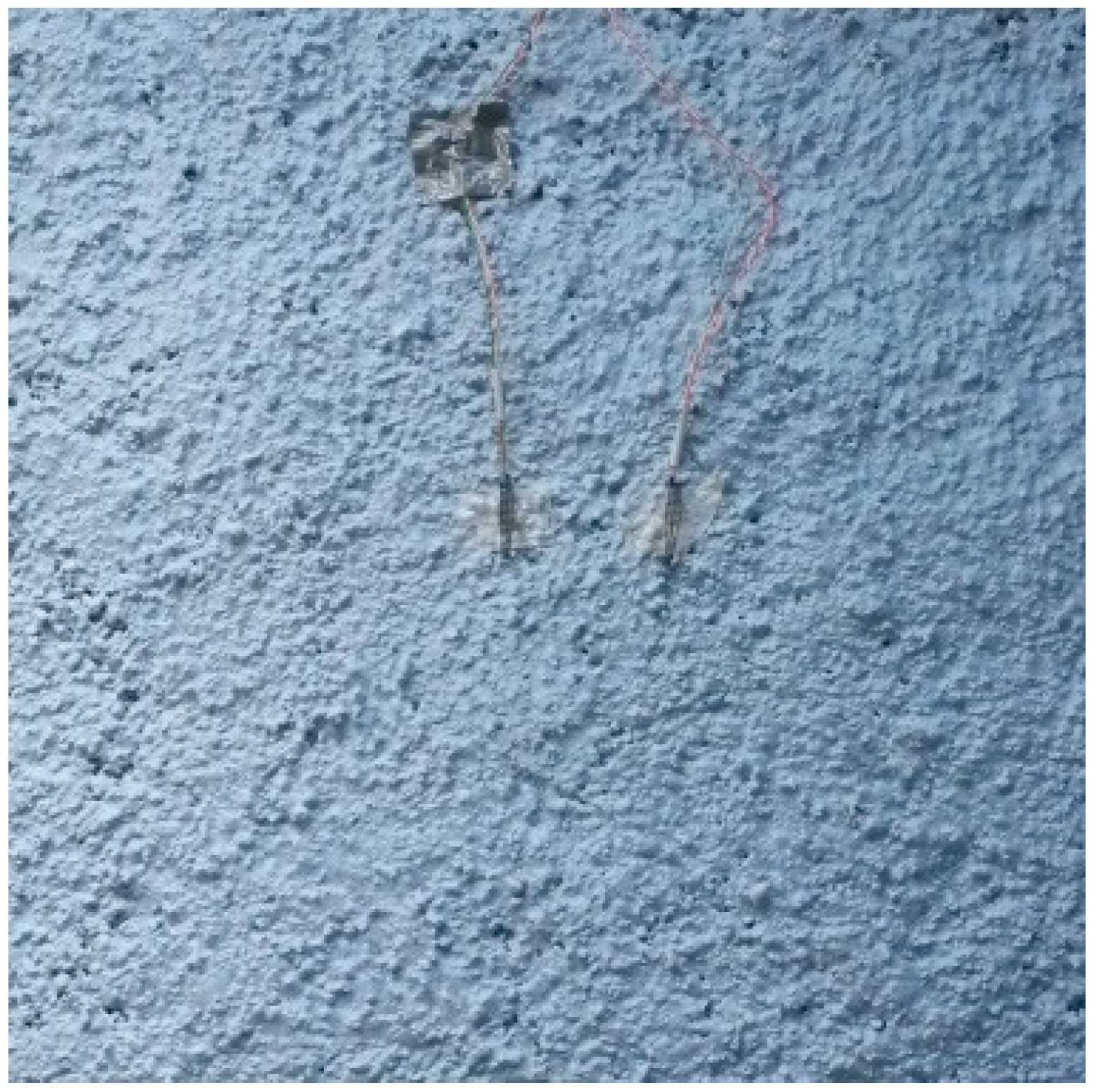
Figure 2.
Front view of the facade with internal division into 12 sections. REF: Reference.
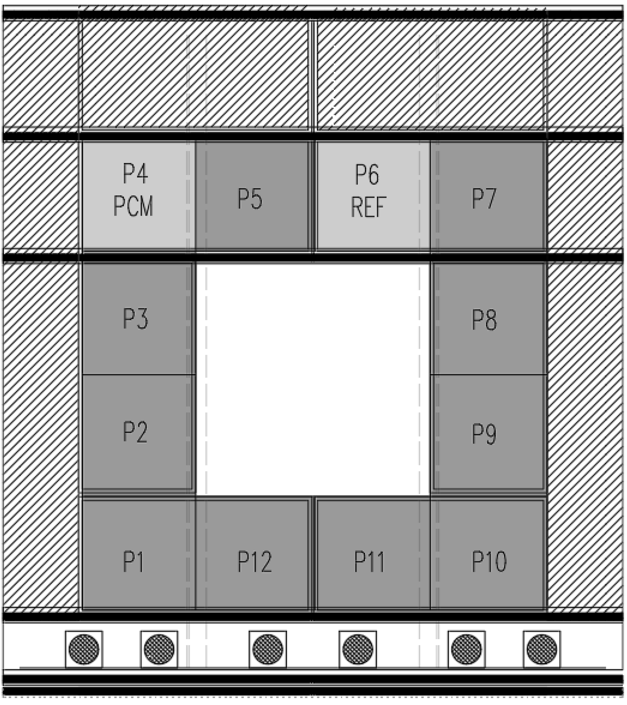
Figure 3.
Cross section through the facade equipped with a PCM composite layer, dimensions in millimeters. PV: photovoltaic.
Figure 3.
Cross section through the facade equipped with a PCM composite layer, dimensions in millimeters. PV: photovoltaic.

Figure 4.
Location of the temperature sensors.

Figure 5.
Verification of the external boundary condition.

Figure 6.
Temperature fluctuations during a selected period of time for proposed and reference cases (in—internal temperature T1, ext—external temperature T7). DH: degree hours.
Figure 6.
Temperature fluctuations during a selected period of time for proposed and reference cases (in—internal temperature T1, ext—external temperature T7). DH: degree hours.
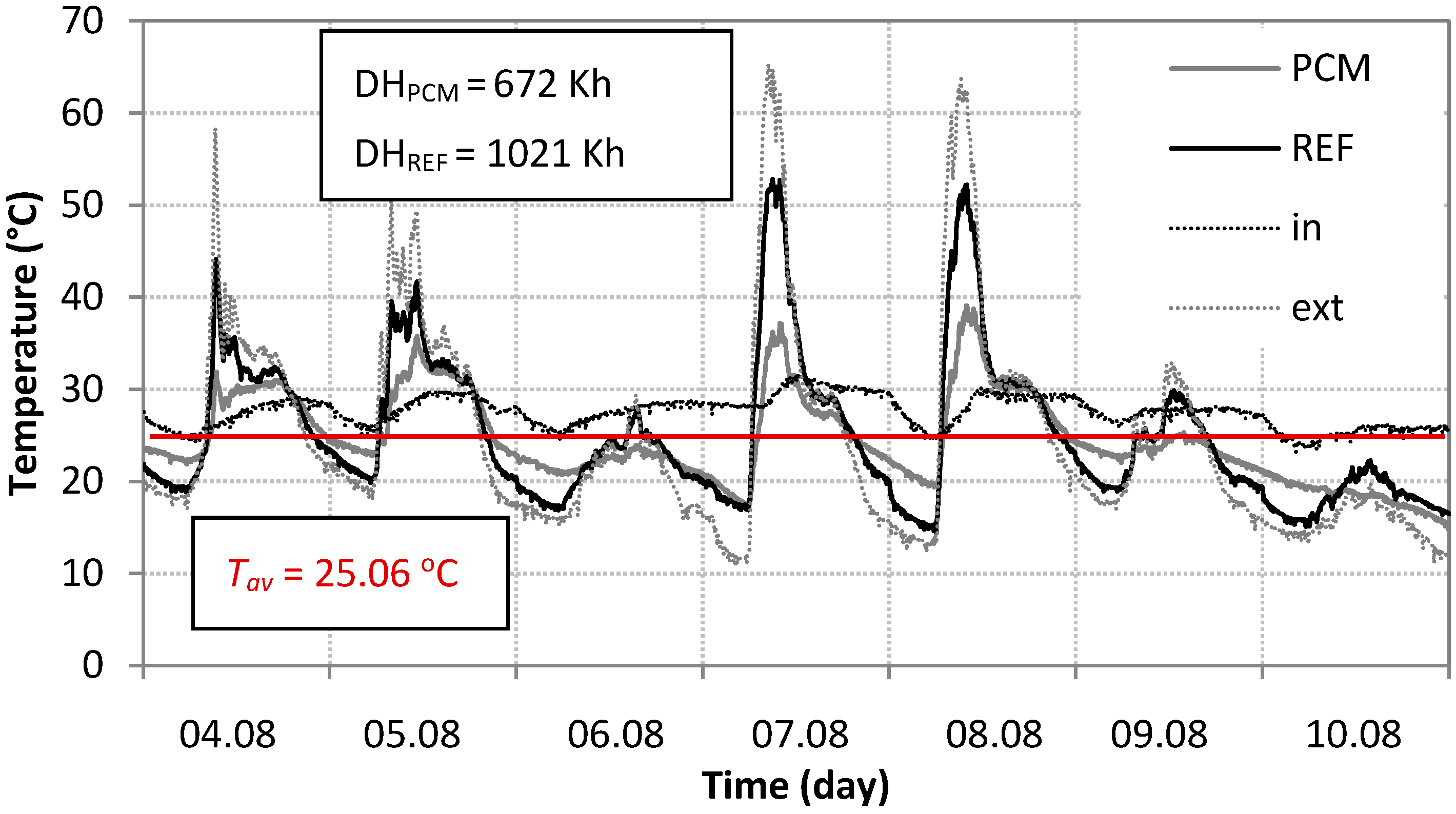
Figure 7.
Example values used for attenuation coefficient calculation.

Figure 8.
The attenuation coefficient (AC) values calculated for test section modified with PCM (PT—results for these days when phase transition occurs, noPT—results for the days without phase transitions).
Figure 8.
The attenuation coefficient (AC) values calculated for test section modified with PCM (PT—results for these days when phase transition occurs, noPT—results for the days without phase transitions).

Figure 9.
The AC values calculated for two test sections: PCM—modified with PCM (P4), REF—reference one (P6).
Figure 9.
The AC values calculated for two test sections: PCM—modified with PCM (P4), REF—reference one (P6).

Figure 10.
Dependence of AC on daily external temperature fluctuations.

Table 1.
Basic characteristics of temperature sensors.
| Type of the Sensor | No of the Sensor | Accuracy (K) | Measurement Range (°C) |
|---|---|---|---|
| TSic 506 | 1–6 | ±0.1 | −10–60 |
| TSic 306 | 7 & 8 | ±0.3 | −50–150 |
© 2017 by the authors. Licensee MDPI, Basel, Switzerland. This article is an open access article distributed under the terms and conditions of the Creative Commons Attribution (CC BY) license (http://creativecommons.org/licenses/by/4.0/).
Share and Cite
MDPI and ACS Style
Heim, D.; Wieprzkowicz, A. Attenuation of Temperature Fluctuations on an External Surface of the Wall by a Phase Change Material-Activated Layer. Appl. Sci. 2018, 8, 11. https://doi.org/10.3390/app8010011
AMA Style
Heim D, Wieprzkowicz A. Attenuation of Temperature Fluctuations on an External Surface of the Wall by a Phase Change Material-Activated Layer. Applied Sciences. 2018; 8(1):11. https://doi.org/10.3390/app8010011
Chicago/Turabian StyleHeim, Dariusz, and Anna Wieprzkowicz. 2018. "Attenuation of Temperature Fluctuations on an External Surface of the Wall by a Phase Change Material-Activated Layer" Applied Sciences 8, no. 1: 11. https://doi.org/10.3390/app8010011
Note that from the first issue of 2016, this journal uses article numbers instead of page numbers. See further details here.