Impact Fatigue of Viscoelastic Materials Subjected to Pounding


1
Institute of Road and Bridge Engineering, Dalian Maritime University, Dalian 116023, China
2
State Key Laboratory of Coastal and Offshore Engineering, Dalian University of Technology, Dalian 116023, China
3
Department of Mechanical Engineering, University of Houston, Houston, TX 77004, USA
*
Authors to whom correspondence should be addressed.
Appl. Sci. 2018, 8(1), 117; https://doi.org/10.3390/app8010117
Submission received: 6 December 2017
/
Revised: 1 January 2018
/
Accepted: 8 January 2018
/
Published: 15 January 2018
(This article belongs to the Special Issue Viscoelastic Solids: Mechanical Behaviour, Contact Mechanics, Fracture and Wear)
Abstract
:The pounding tuned mass damper (PTMD) is a novel vibration control device that can be used for many different structures. The PTMD utilizes a viscoelastic delimiter to enhance its vibration control effectiveness and robustness though pounding between the tuned mass and the viscoelastic material. However, the viscoelastic material is subjected to repeated poundings during its service life, which influences the property of the material and degrades its energy dissipation ability. Therefore, this study investigates the fatigue behavior of the viscoelastic material under impact loading. An experimental apparatus, which can generate and sense the lateral impacts, is designed and fabricated to facilitate the fatigue study of the viscoelastic material subject to impact loading. Based on experimental data, the pounding stiffness and the hysteresis loops are employed to characterize the behavior of the material. It is revealed that the impact fatigue process can be divided into two phases: the cyclic-hardening phases and the cyclic-softening phase. The energy dissipation is firstly reduced, and then increased, by the repeated impacts. In summary, with a total of 360,000 impacts, the viscous elastic material is still effective in dissipating impact energy.
1. Introduction
The tuned mass damper (TMD) is a classical vibration control technique. Its concept dates back to 1909, when Frahm proposed a vibration control device called a dynamic vibration absorber [1]. Due to its simplicity and effectiveness, the TMD technology has been widely used in vibration mitigation for many types of structures. However, the vibration reduction efficiency will deteriorate if its frequency shifts away from the target value. To compensate for this de-tuning effect, many active and semi-active solutions were proposed. Semi-active vibration absorbers, which enabled real-time tuning of the frequency and the damping, were proposed by Weber and his collaborators [2,3,4]. Mishra et al. [5] replaced the linear spring in a traditional TMD with a spring made of shape memory alloy (SMA). The simulation results demonstrated significant improvements of the SMA-TMD in the control efficiency at a much reduced mass ratio compared with a linear TMD.
Although TMDs incorporated with smart materials can achieve improved control effectiveness and robustness, this combined system requires reliable instant feedback, which will increase the cost of the vibration control system. The pounding tuned mass damper (PTMD) employs the energy dissipation scheme through impacts, which dramatically improves its vibration reduction capacity. The schematics of the TMD and the PTMD are compared in Figure 1. As shown in the figure, the essential difference between the PTMD and the regular TMD is a delimiter, which is covered by viscoelastic materials. When there is only a slight vibration of the primary structure, the tuned mass will vibrate freely between the two delimiters, and the PTMD will act as a traditional TMD. When the motion of the primary structure exceeds a certain level, the tuned mass will pound on the delimiter as an impact damper. Energy can be dissipated through the collision [6,7]. In other words, the viscoelastic delimiter introduced the energy dissipation mechanism for impacts to the PTMD. Therefore, the PTMD is more effective than the regular TMD in vibration reduction [8,9]. Another benefit of the viscoelastic delimiter is that it can enhance the robustness of the PTMD. According to the literature [9,10], in the off-tuned case, the relative motion between the tuned mass and the delimiter is larger than that of the optimal-tuned case. Therefore, in the off-tuned case, the added mass will impact the viscoelastic material more severely, generating a larger pounding force, resulting in larger momentum exchange and energy dissipation. This can compensate for the vibration effectiveness deteriorated by the detuning effect.
Even though the impacts of the viscoelastic material have improved the vibration effectiveness and robustness of the PTMD, the repeated impacts may damage the material and deteriorate its long term performance [11,12,13]. Moreover, the PTMD is often applied to structures located in extreme environments (e.g., subsea jumpers and offshore platforms). Therefore, it is expected to function well for two or more decades, since it is very difficult to repair or replace the PTMD. During long-term service, a PTMD may undergo many cycles of impacts. The repeated impacts may damage the viscoelastic material and degrade its vibration control effectiveness. Thus, it is necessary to conduct an impact-fatigue study of the viscoelastic material.
Over the past decades, the viscoelastic material has been intensively studied [14,15,16]. Carbone et al. proposed a new experimental device to investigate the crack propagation in viscoelastic materials [17]. Putignano et al. investigated the contact mechanics between rough surfaces of the viscoelastic materials [18]. Carbone and Putignano proposed a methodology to numerically investigate the steady-state sliding or rolling contact of viscoelastic materials [19]. Several studies have focused on the impact fatigue property of the viscoelastic material. In order to apply different types of impacts, researchers have proposed several testing machines, such as weight dropping machines [20,21,22], swinging pendulum machines [23], and rotary machines [24]. Influencing parameters, such as testing temperature [25], the number of impacts [23] and contact time [22], were studied. However, these studies focus mainly on the tensile fatigue of the viscoelastic material, while the viscoelastic material of the PTMD only undertakes the compressional impacts. Moreover, the samples investigated in the literature are manufactured as thin plates, and these studies mainly focus on the fracture process of the samples. These studies are all different from the dynamic loadings that a viscoelastic material will experience in the PTMD. Therefore, an impact-fatigue study on the viscoelastic material of the PTMD is still necessary.
This paper presents an experimental study of the impact fatigue process of the viscoelastic material of the PTMD. The experimental device is based on a prototype PTMD used for the vibration control of pipeline structures. It is specially designed to generate cyclic lateral impacts on the specimen. The pounding stiffness is employed to interpret the fatigue process of the viscoelastic material.
2. Impact-Fatigue Test
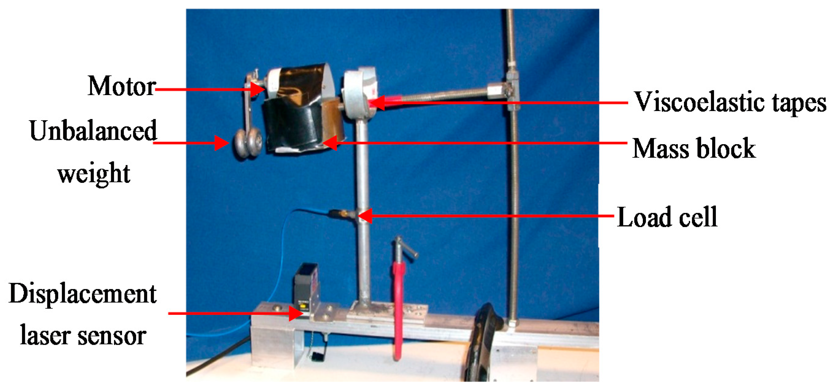
The impact-fatigue test is performed by using the experimental apparatus shown in Figure 2. The device consists of an L-shape structure, an exciter, an impact component, and sensors. The L-shape structure is made up of two steel rods and an added mass. The two steel rods are placed in the vertical and horizontal direction; their diameter is 12 mm. The added mass is fixed at the free end of the horizontal rod, and its mass is 1.5 kg. The exciter includes a motor (Pololu, Las Vegas, NV, USA) and an unbalanced mass. It can force the L-shape structure to oscillate in the vertical direction, and the horizontal rod will collide with the impact component under it. The specimen, which is adhered on the surface of the impact component, is a seven-layer 3 M VHB4936 dual adhesive viscoelastic material (Minnesota Mining and Manufacturing, St. Paul, MN, USA), which is also used in the actual PTMDs. Beneath the specimen, a load cell is installed to measure the pounding force. A laser sensor is placed 100 mm beneath the mass block to measure the displacement of the mass. The sampling frequency is 1 kHz. The testing temperature was kept around 20 °C.
3. Results and Discussion
3.1. Changes of Appearance
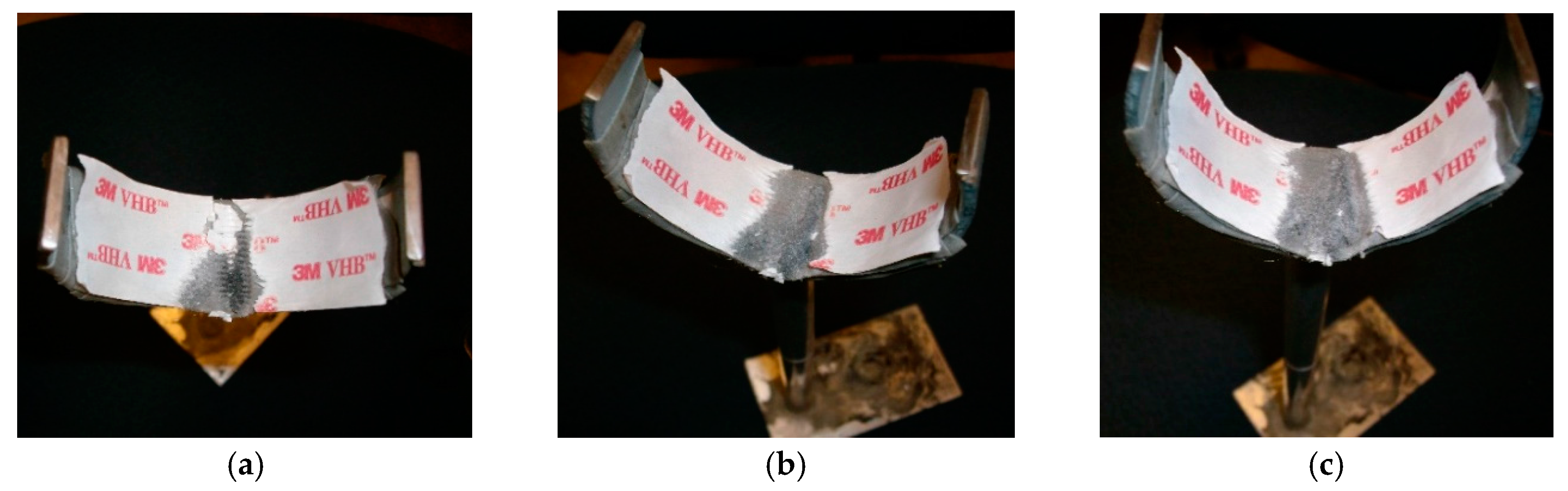
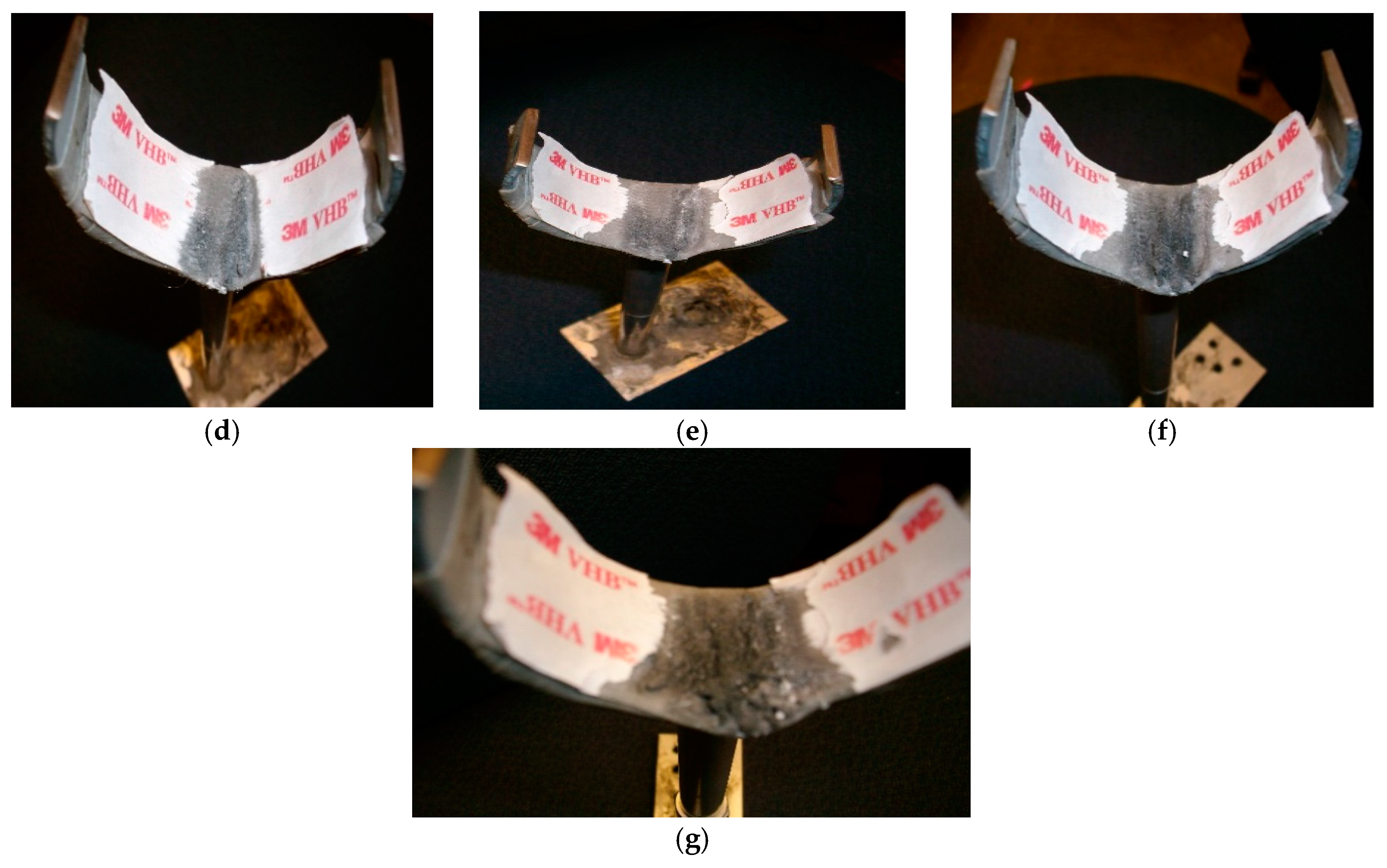
During the impact-fatigue test, the cyclic impact load was stopped every 10,000 times. A photo was taken at each interval. Figure 3 shows the appearances of the sample after these impacts. The tape in grey color is the viscoelastic material, and the tape in white color with red letters are the outer packing of the viscoelastic tape. As the cycles increase, the impact area increases, and the thickness of the sample decreases. After 360,000 cycles (Figure 3g), the viscoelastic material was severely damaged, and the metal was exposed in some areas.
3.2. Fatigue Effect on Pounding Stiffness
In previous studies [8], it was found that the most accurate pounding force model was based on a Hertz contact element, in conjunction with a damper that is active only during the approaching period of the impact. The mathematical expression is as follows:
where describes the deformation of the colliding bodies; denotes the relative velocity between them; is the pounding stiffness; and is the pounding damping which at any instant of time can be obtained by:
where and are the masses of the two colliding bodies, and is the impact damping ratio correlated with the coefficient of restitution , which is defined as the relation between the post-impact (final) relative velocity, and the prior-impact (initial) relative velocity, .
In this study, the pounding force and the displacement of the colliding bodies are recorded every 10,000 cycles. Based on this data, the pounding stiffness can be estimated by the Curve Fitting Toolbox in MATLAB/Simulink. Figure 4 shows the pounding force model established in MATLAB/Simulink. The estimation method is a nonlinear least-squares method.
Figure 5 shows the variation of the pounding stiffness versus the number of impacts. As shown in the figure, the impact fatigue process can be divided into two phases. The first phase is from the beginning to 180,000 cycles. In this phase, the viscoelastic material was compressed, and the thickness was reduced by the repeated impacts. The pounding stiffness was increased from 15,000 N/m1.5 to 35,000 N/m1.5. This phenomenon can be regarded as cyclic-hardening. After that, even though the cyclic impacts again compress the viscoelastic material and reduce its thickness, the pounding stiffness was decreased from 35,000 N/m1.5 to 9000 N/m1.5. This implied that the viscoelastic was softened by the continued impacts. This phenomenon was referred as cyclic-softening.
3.3. Changes of Hysteresis Loops
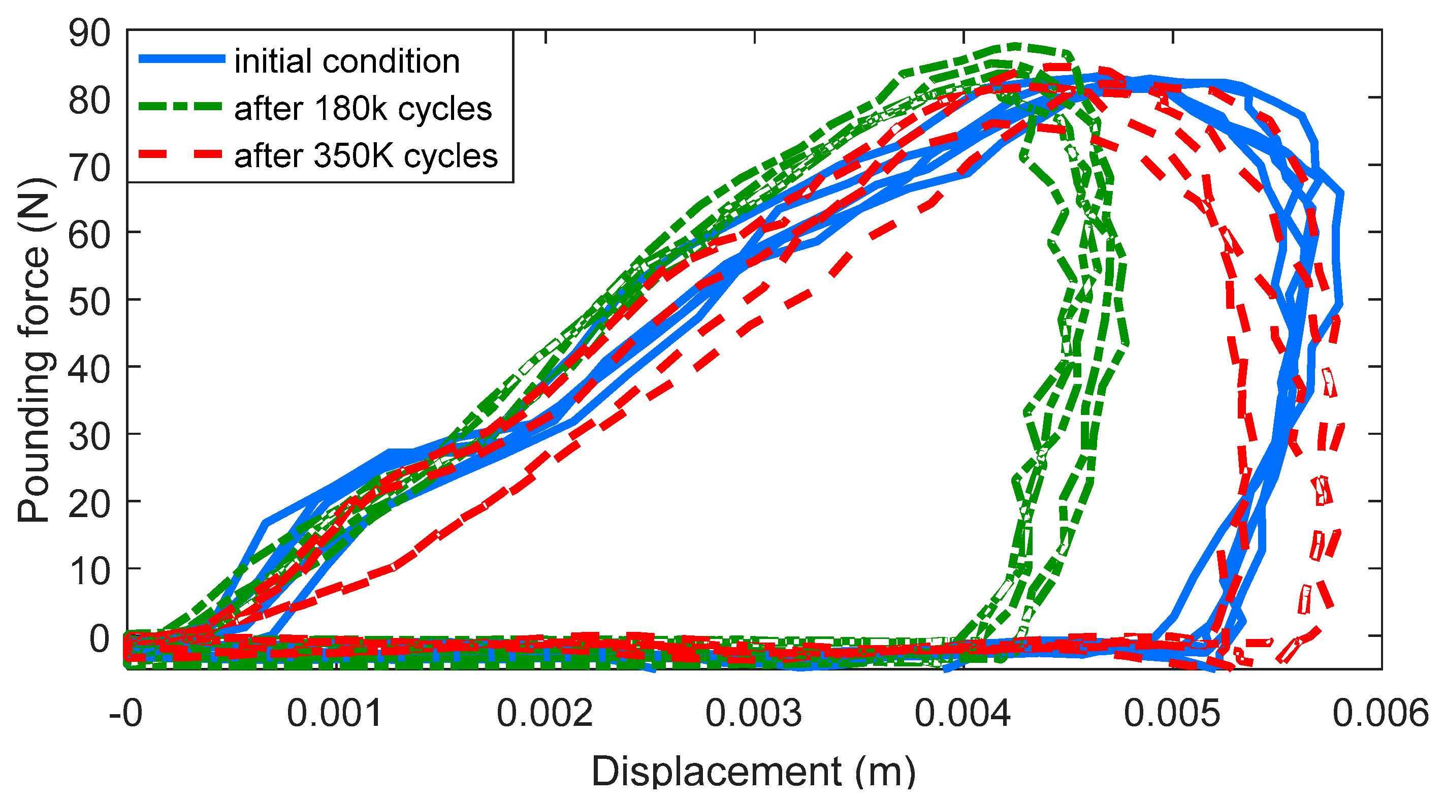
In order to further investigate the influence on the mechanical property of the viscoelastic material, the hysteresis loops of the material after repeated impacts are plotted in Figure 6. The solid lines show the hysteresis loops before the impact fatigue test, and the dash dot lines are the hysteresis loops after 180,000 cycles of impacts. The dashed lines are the hysteresis loops after 350,000 cycles of impacts. The curves also indicated a cyclic-hardening process and a cyclic-softening process. The slope of the hysteresis loops can indicate the stiffness of the viscoelastic material. The slope of the dash dot line is steeper than that of the solid line and the dashed line, which implies that the material after 180,000 impacts is stiffer than the initial condition and after 350,000 impacts.
The hysteresis loop can also reflect the energy dissipation ability. The area surrounded by the solid line is smaller than that of the dash dot line and the dashed line, which indicates that the viscoelastic material after 180,000 impacts can consume less energy than the initial condition and than after 350,000 impacts.
3.4. Changes of the Dissipated Energy per Cycle
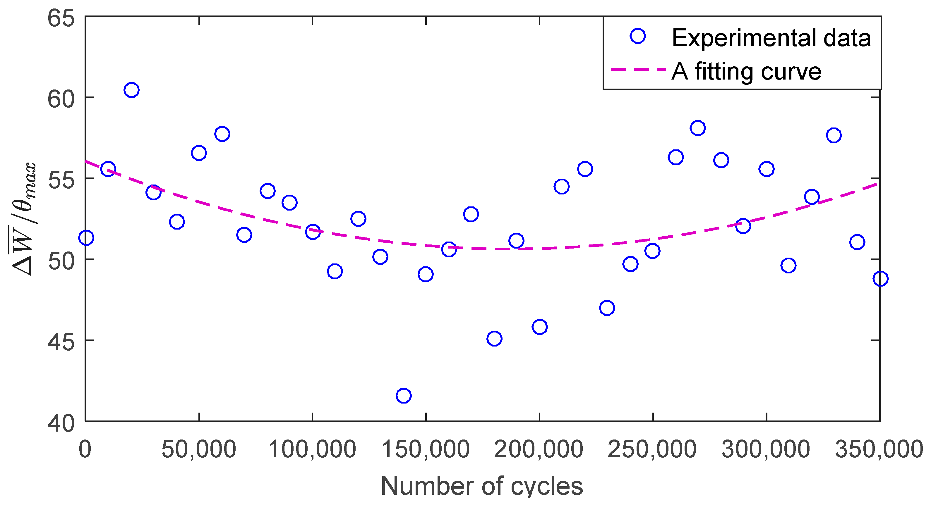
To further quantify the damping effect of the viscoelastic material, the energy dissipated per cycle is calculated as follows:
where denotes the dissipated energy; is the impact force, and denotes the deformation of the viscoelastic material. Due to the limitation of the experimental apparatus, the intensity of impact is not precisely controlled. Since can be influenced by the impact intensity, a normalized parameter is defined as
where δmax is the maximum impact depth.
Figure 7 shows the dissipated energy as a function of the number of impact cycles. In the initial condition, the viscoelastic material dissipated an average energy of 51.29 J/m per cycle. Then, was decreased by the repeated impacts. After 180,000 cycles, it was decreased to 45.14 J/m per cycle. After that, was increased with more impacts. When it was impacted the 350,000th time, it reached 48.83 J/m per cycle.
4. Conclusions
A specially designed impact-fatigue testing device was established to investigate the fatigue trend of the viscoelastic material used in the PTMD. The pounding stiffness was employed to interpret the property of the viscoelastic material. A cyclic-hardening process and a cyclic-softening process were recognized. During the first 180,000 cycles of impacts, the viscoelastic material tapes were compressed together, their thickness was reduced, and the pounding stiffness was increased from its initial value of 15,000 N/m1.5 to 35,000 N/m1.5. This is referred to as a cyclic-hardening process. Afterward, pounding stiffness of the viscoelastic material was decreased to 9000 N/m1.5 with more strikes. This is referred to as a cyclic-softening process. The hysteresis loops and dissipated energy per cycle also reveal the cyclic-hardening and cyclic-softening processes. In summary, with a total of 360,000 impacts, the viscous elastic material is still effective in dissipating impact energy.
Acknowledgments
This research was partially founded by the National Key Research and Development Plan of China (No. 2016YFC0701103), the Fundamental Research Funds for the Central Universities (Nos. 3132017023 and 3132014326) and the National Natural Science Foundation of China (No. 51578114).
Author Contributions
All authors discussed and agreed upon the idea, and made scientific contributions. Peng Zhang, and Gangbing Song designed the experiments and wrote the paper, Peng Zhang performed the experiments. Peng Zhang and Linsheng Huo analyzed the data. Linsheng Huo revised the paper.
Conflicts of Interest
The authors declare no conflict of interest.
References
- Frahm, H. Device for Damping Vibration of Bodies. U.S. Patent No. 989,958, 18 April 1911. [Google Scholar]
- Weber, F. Optimal semi-active vibration absorber for harmonic excitation based on controlled semi-active damper. Smart Mater. Struct. 2014, 23. [Google Scholar] [CrossRef]
- Weber, F.; Maślanka, M. Precise stiffness and damping emulation with MR dampers and its application to semi-active tuned mass dampers of wolgograd bridge. Smart Mater. Struct. 2014, 23. [Google Scholar] [CrossRef]
- Weber, F. Semi-active vibration absorber based on real-time controlled MR damper. Mech. Syst. Signal Process. 2014, 46, 272–288. [Google Scholar] [CrossRef]
- Mishra, S.K.; Gur, S.; Chakraborty, S. An improved tuned mass damper (SMA-TMD) assisted by a shape memory alloy spring. Smart Mater. Struct. 2013, 22. [Google Scholar] [CrossRef]
- Hatzigeorgiou, G.D.; Pnevmatikos, N.G. Maximum damping forces for structures with viscous dampers under near-source earthquakes. Eng. Struct. 2014, 68, 1–13. [Google Scholar] [CrossRef]
- Hatzigeorgiou, G.D.; Pnevmatikos, N.G. On the seismic response of collided structures. Int. J. Civ. Archit. Struct. Constr. Eng. 2014, 8, 750–755. [Google Scholar]
- Zhang, P.; Song, G.; Li, H.N.; Lin, Y.X. Seismic control of power transmission tower using pounding TMD. J. Eng. Mech. 2013, 139, 1395–1406. [Google Scholar] [CrossRef]
- Xue, Q.; Zhang, J.; He, J.; Zhang, C. Control performance and robustness of pounding tuned mass damper for vibration reduction in sdof structure. Shock Vib. 2016, 2016. [Google Scholar] [CrossRef]
- Li, H.; Zhang, P.; Song, G.; Patil, D.; Mo, Y. Robustness study of the pounding tuned mass damper for vibration control of subsea jumpers. Smart Mater. Struct. 2015, 24. [Google Scholar] [CrossRef]
- Li, Y.; Zhang, W.; Ming, A.B.; Yang, Z.W.; Tian, G. A new way for revealing the damage evolution of impacted cfrp laminate under compression-compression fatigue load based on thermographic images. Compos. Struct. 2017, 176, 1–8. [Google Scholar] [CrossRef]
- Wang, J.; Gutierrez, M.S. Molecular simulations of cyclic loading behavior of carbon nanotubes using the atomistic finite element method. J. Nanomater. 2009, 2009, 1–9. [Google Scholar] [CrossRef]
- Spinu, S.; Cerlinca, D. Modelling of rough contact between linear viscoelastic materials. Model. Simul. Eng. 2017, 2017. [Google Scholar] [CrossRef]
- Balemans, C.; Hulsen, M.A.; Anderson, P.D. Sintering of two viscoelastic particles: A computational approach. Appl. Sci. 2017, 7, 516. [Google Scholar] [CrossRef]
- Sun, W.; Wang, Z.; Liu, R.; Yan, X. Inverse identification of the frequency-dependent mechanical parameters of a viscoelastic core layer based on the vibration response. Appl. Sci. 2017, 7, 455. [Google Scholar] [CrossRef]
- Wu, Y.; Wang, H.; Li, A. Parameter identification methods for hyperelastic and hyper-viscoelastic models. Appl. Sci. 2016, 6, 386. [Google Scholar] [CrossRef]
- D’Amico, F.; Carbone, G.; Foglia, M.M.; Galietti, U. Moving cracks in viscoelastic materials: Temperature and energy-release-rate measurements. Eng. Fract. Mech. 2013, 98, 315–325. [Google Scholar] [CrossRef]
- Putignano, C.; Carbone, G.; Dini, D. Mechanics of rough contacts in elastic and viscoelastic thin layers. Int. J. Solids Struct. 2015, 69–70, 507–517. [Google Scholar] [CrossRef]
- Giuseppe, C.; Carmine, P. A novel methodology to predict sliding and rolling friction of viscoelastic materials: Theory and experiments. J. Mech. Phys. Solids 2013, 61, 1822–1834. [Google Scholar]
- Prayogo, G.; Homma, H.; Soemardi, T.P.; Danardono, A.S. Impact fatigue damage of gfrp materials due to repeated raindrop collisions. Trans. Indian Inst. Met. 2011, 64, 501–506. [Google Scholar] [CrossRef]
- Sevkat, E.; Liaw, B.; Delale, F.; Raju, B.B. Effect of repeated impacts on the response of plain-woven hybrid composites. Compos. Part B Eng. 2010, 41, 403–413. [Google Scholar] [CrossRef]
- Kawaguchi, T.; Nishimura, H.; Ito, K.; Sorimachi, H.; Kuriyama, T.; Narisawa, I. Impact fatigue properties of glass fiber-reinforced thermoplastics. Compos. Sci. Technol. 2004, 64, 1057–1067. [Google Scholar] [CrossRef]
- Bora, M.Ö.; Çoban, O.; Sinmazçelik, T.; Cürgül, İ.; Günay, V. On the life time prediction of repeatedly impacted thermoplastic matrix composites. Mater. Des. 2009, 30, 145–153. [Google Scholar] [CrossRef]
- Roy, R.; Sarkar, B.K.; Bose, N.R. Impact fatigue of glass fibre–vinylester resin composites. Compos. Part A Appl. Sci. Manuf. 2001, 32, 871–876. [Google Scholar] [CrossRef]
- Matthieu, P.; Emmanuel, M.; Pascal, R.; Godin, N.; R’Mili, M.; Fantozzi, G.; Lamon, J.L. Damage sensitivity and acoustic emission of sic/sic composite during tensile test and static fatigue at intermediate temperature after impact damage. In Mechanical Properties and Performance of Engineering Ceramics and Composites VII; John Wiley & Sons, Inc.: Hoboken, NJ, USA, 2012. [Google Scholar]
Figure 1.
Schematic of (a) tuned mass damper (TMD); (b) pounding tuned mass damper (PTMD).
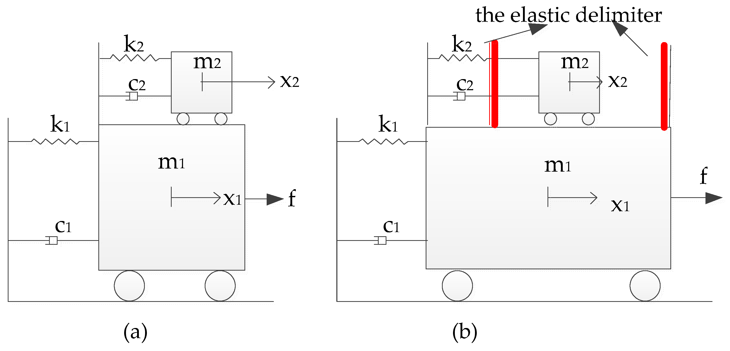
Figure 2.
Experimental setup.

Figure 3.
Surface of the sample after cyclic impacts: (a) after 10,000 cycles; (b) after 50,000 cycles; (c) after 100,000 cycles; (d) after 150,000 cycles; (e) after 200,000 cycles; (f) after 250,000 cycles; (g) after 360,000 cycles.
Figure 3.
Surface of the sample after cyclic impacts: (a) after 10,000 cycles; (b) after 50,000 cycles; (c) after 100,000 cycles; (d) after 150,000 cycles; (e) after 200,000 cycles; (f) after 250,000 cycles; (g) after 360,000 cycles.


Figure 4.
Pounding force model established in MATLAB/Simulink.
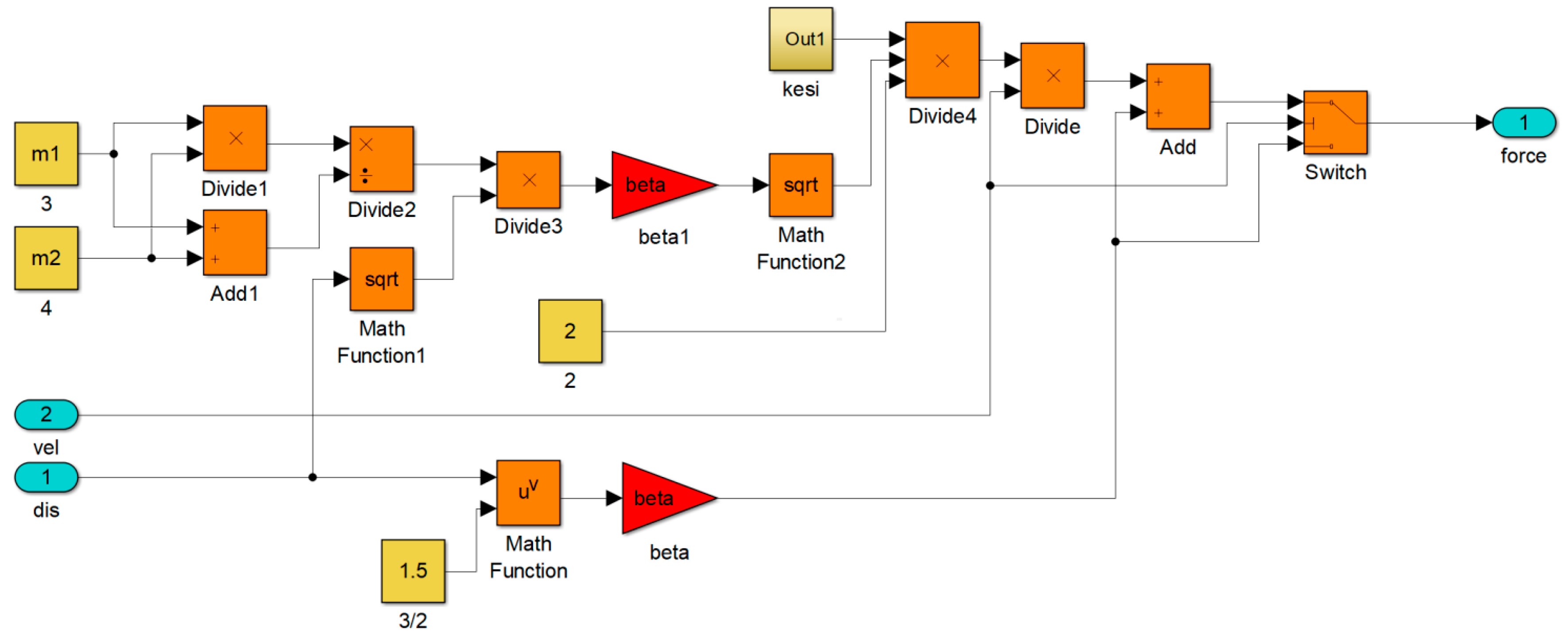
Figure 5.
Pounding stiffness after cyclic impacts.
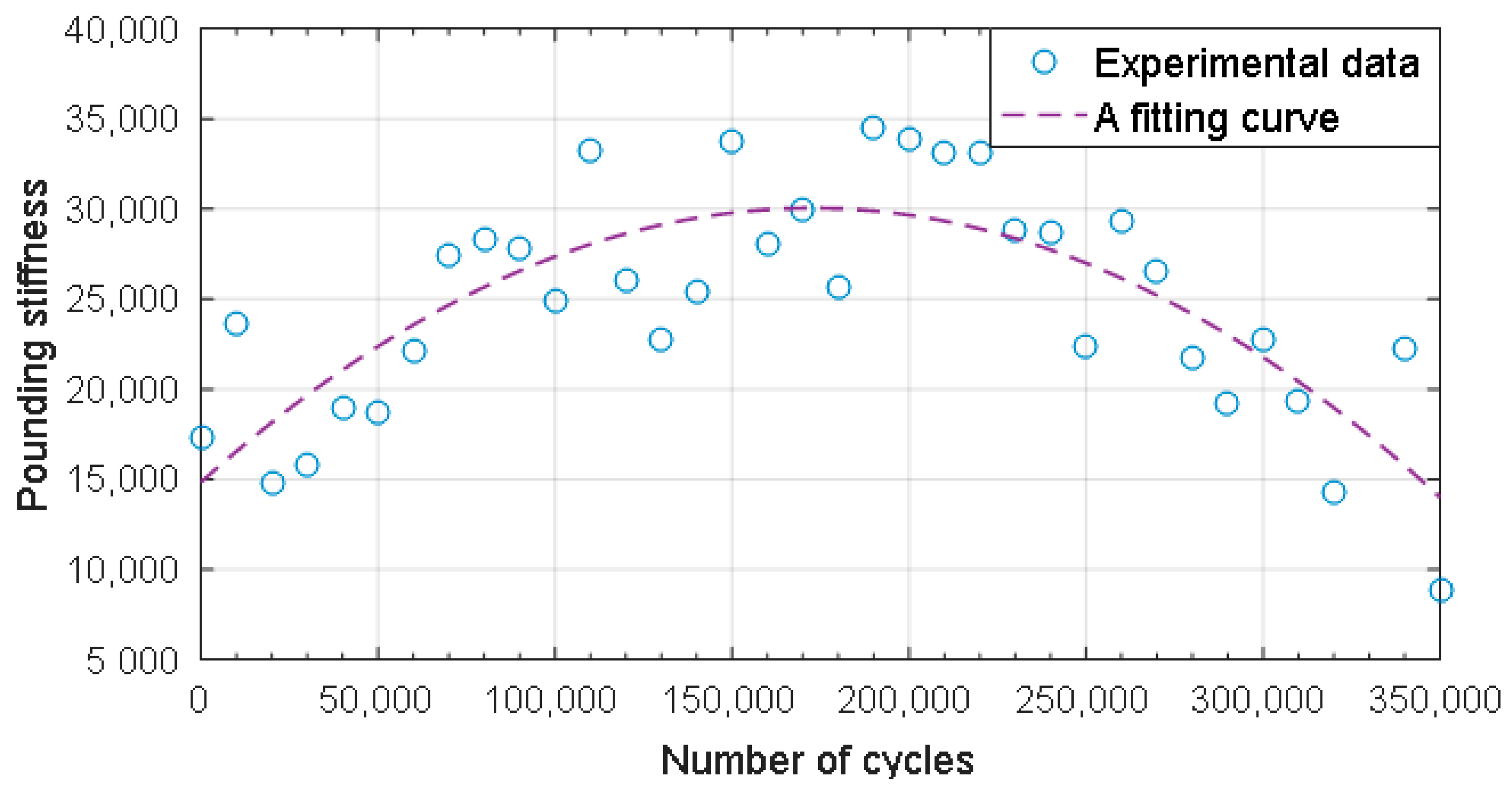
Figure 6.
Typical hysteresis loops of the viscoelastic material after cyclic impacts.

Figure 7.
Typical hysteresis loops of the viscoelastic material after cyclic impacts.
© 2018 by the authors. Licensee MDPI, Basel, Switzerland. This article is an open access article distributed under the terms and conditions of the Creative Commons Attribution (CC BY) license (http://creativecommons.org/licenses/by/4.0/).
Share and Cite
MDPI and ACS Style
Zhang, P.; Huo, L.; Song, G. Impact Fatigue of Viscoelastic Materials Subjected to Pounding. Appl. Sci. 2018, 8, 117. https://doi.org/10.3390/app8010117
AMA Style
Zhang P, Huo L, Song G. Impact Fatigue of Viscoelastic Materials Subjected to Pounding. Applied Sciences. 2018; 8(1):117. https://doi.org/10.3390/app8010117
Chicago/Turabian StyleZhang, Peng, Linsheng Huo, and Gangbing Song. 2018. "Impact Fatigue of Viscoelastic Materials Subjected to Pounding" Applied Sciences 8, no. 1: 117. https://doi.org/10.3390/app8010117
Note that from the first issue of 2016, this journal uses article numbers instead of page numbers. See further details here.