Incoherent Digital Holography: A Review

1
Department of Photonics, Feng Chia University, 100 Wenhwa Rd., Seatwen, Taichung 40725, Taiwan
2
Faculty of Engineering Science, Kansai University, 3-3-35 Yamate-cho, Suita, Osaka 564-8680, Japan
3
PRESTO, Japan Science and Technology Agency, 4-1-8 Honcho, Kawaguchi, Saitama 332-0012, Japan
4
Center for Optical Research & Education (CORE), Utsunomiya University, 7-1-2 Yoto, Utsunomiya 321-8585, Japan
5
Bradley Department of Electrical and Computer Engineering, Virginia Tech, Blacksburg, VA 24061, USA
*
Author to whom correspondence should be addressed.
Appl. Sci. 2018, 8(1), 143; https://doi.org/10.3390/app8010143
Submission received: 31 December 2017
/
Revised: 12 January 2018
/
Accepted: 16 January 2018
/
Published: 20 January 2018
(This article belongs to the Special Issue Holography and 3D Imaging: Tomorrows Ultimate Experience)
Abstract
:Digital holography (DH) is a promising technique for modern three-dimensional (3D) imaging. Coherent holography records the complex amplitude of a 3D object holographically, giving speckle noise upon reconstruction and presenting a serious drawback inherent in coherent optical systems. On the other hand, incoherent holography records the intensity distribution of the object, allowing a higher signal-to-noise ratio as compared to its coherent counterpart. Currently there are two incoherent digital holographic techniques: optical scanning holography (OSH) and Fresnel incoherent correlation holography (FINCH). In this review, we first explain the principles of OSH and FINCH. We then compare, to some extent, the differences between OSH and FINCH. Finally, some of the recent applications of the two incoherent holographic techniques are reviewed.
1. Introduction
The demand for three-dimensional (3D) imaging [1,2] has been increasing more and more in recent years. The acquisition of 3D information is important, particularly in the fields of life science [1] and information science [2]. To record the 3D position, shape, and image of an object, many types of methods, such as dual focus-plane imaging [1], integral imaging with a lens array [2], scanning and nonlinear optics [3], coherent diffraction imaging [4], and holography [5], have been actively researched. However, as a result of advanced computer and photonic devices, digital holography (DH) [6,7] can record a hologram of a real 3D object on a two-dimensional (2D) plane and reconstruct its image digitally, which has given a promising 3D technique in the last decade. DH is an interference technique, and the light source should be both spatially and temporally coherent to guarantee the success of the interference. In practice, there is no perfect coherent source, and thus holographic recording is always performed by a partially coherent source. For a source with a high spatial coherence but low temporal coherence, interference can be performed when the time delay between the object light and the reference light is smaller than the coherence time. This is also the fundamental concept of “low-coherence DH”, which has been applied to perform 3D imaging and sectional reconstruction [8,9,10,11,12]. On the other hand, holographic recording by using a source with a high temporal coherence but low spatial coherence is more difficult, because it is difficult to generate a mutually coherent reference light from such a light source. This is the case that we are interested in for this paper, and it is referred to as “incoherent DH” henceforth.
There are two different kinds of techniques to realize incoherent DH. The first technique is optical scanning holography (OSH) [13], which was first proposed in 1979 by Poon and Korpel and was pioneered by Poon [14,15,16]. OSH does not perform interference between the object light and the reference light. Instead, a heterodyne interference fringe pattern without the information of the object is first generated, and the object target is raster scanned by this interference pattern. The scattered light from the object is then detected and demodulated to obtain a resulting hologram. So far, OSH has been applied to remotesensing [17,18], cryptography [19,20,21], microscopy [22,23,24,25,26,27,28,29] and 3D display [30,31,32]. However, the most important feature of OSH is the ability to record incoherent holograms. In OSH, although the light source is always highly coherent spatially and temporally, the recorded hologram can be either spatially coherent or incoherent. The reason is that the spatial coherence of OSH depends on the recording geometry. If the active area of the detector is large enough, the hologram is formed by the superposition of the irradiance response of the object target, resulting in an incoherent hologram. Therefore, OSH can record incoherent holograms at the wavelength of the light source. Subsequently, OSH can also record fluorescence holograms [22,26], which is an incoherent holographic technique of single-wavelength excitation and continuous-spectrum emission and detection.
The second technique of incoherent DH is Fresnel incoherent correlation holography (FINCH) [33]. FINCH is based on a single-path and self-interference interferometer, which generates an incoherent hologram that is composed of the summation of Fresnel zone plate (FZP) patterns. Rosen and Brooker initially presented a single-path and self-interference holography setup adopting a spatial light modulator (SLM) [33,34]. In the optical path, an optical element converts an object wave into two wavefronts that have different curvature radii from each other. A birefringent crystal, SLM, or double-focus lens is typically selected as the optical element to generate the two waves. FINCH has been applied to color 3D imaging [34] and microscopy [35,36,37,38]. In FINCH, spatially and temporally incoherent light, such as light from a light emitting diode (LED) or sunlight, is available as a light source. The reason is that the optical path difference between the generated two waves is short enough to form an incoherent hologram. The center of a FZP pattern and the fineness of interference fringes are related to the 3D position of each object point, and the 3D image of an object is reconstructed subsequently from the recorded incoherent hologram. A self-referenced interferometer combined with a Michelson [39,40,41,42,43,44], Mach–Zehnder [45], or triangular [46] interferometer can record an incoherent hologram, and these have been applied to color 3D imaging of a scene [41] and the 3D position measurement of nanoparticles [42]. A single-path system can be constructed with a more compact configuration and higher light efficiency, owing to the adoption of a conoscopic setup [47,48]. Indeed, FINCH is a revival of common-path incoherent holography, and the difference between the various techniques is the use of a SLM and digital optics such as the numerical calculations of diffraction integrals and phase-shifting interferometry.
2. Principle of OSH
2.1. Setup of OSH
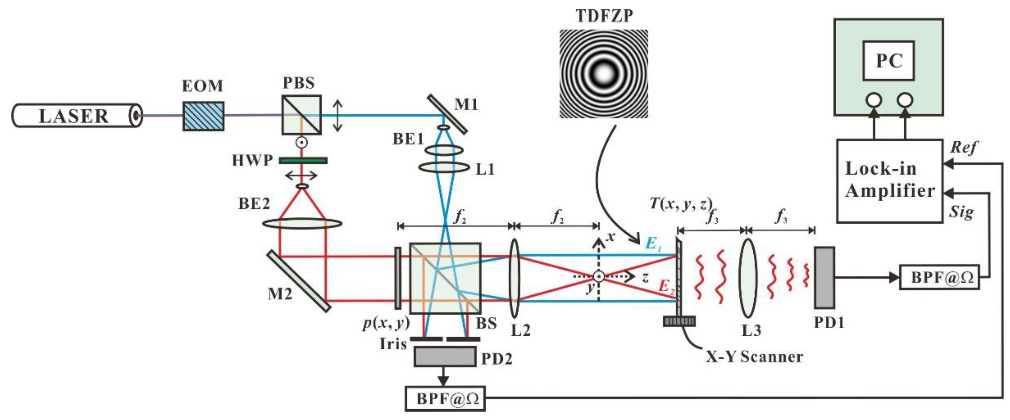
Figure 1 illustrates the schematic of a typical OSH system. A laser of wavelength and angular frequency is used as the source and the laser beam is separated by a polarizing beamsplitter (PBS). The transmitting beam is collimated by the beam expander BE1 and focused by the lens L1; the reflected beam from the PBS is collimated by the beam expander BE2. In the path of the reflected beam, a pupil, , located in the front focal plane of lens L2, is inserted to modify the properties of the recorded hologram. The two beams are recombined by the beamsplitter (BS) and projected toward the object through lens L2. The object is located at a distance away from the back focal plane of the lens. The interference pattern from the two beams is formed on the object. In the present case, we choose , and we have the interference of a spherical wave and a plane wave, which is a FZP on the object. A frequency shift between the two beams is introduced by a frequency shifter, such as an electro-optic modulator (EOM), as shown in Figure 1. Therefore, the interference fringe in the object space oscillates at the modulation angular frequency of the EOM and thus is called a time-dependent Fresnel zone plate (TDFZP). The object is mounted on an x-y translational stage and is raster scanned by the TDFZP; the light scattered from the object is detected by a single-pixel detector, that is, a photodetector, PD1, as shown in the figure, to give a signal (Sig) as an input of the lock-in amplifier. Meanwhile, a reference signal is detected by photodetector PD2 at the non-scanning channel of the interferometer to give a reference signal as another signal to the lock-in amplifier. Finally, the outputs of the lock-in amplifier, which contain the amplitude and phase information of the scanned object, are digitized and arranged as a complex hologram in a computer.
There are several various versions of OSH systems. By using three lasers with different wavelengths and three EOMs, a color-scanned hologram has been recorded in single scanning [49]. The EOM can be replaced by acousto-optic modulators (AOMs) to generate the frequency shift [50]. Homodyne scanning is also an alternative choice to record a scanned hologram without a frequency shifter [51]. However, in homodyne scanning holography, multiple scannings are required to remove the zeroth-order beam and twin image resulting from the hologram. The object-scanning scheme as illustrated in Figure 1 can be replaced by a beam-scanning scheme for high-speed applications [17]. In addition, the proposed dual-beam scanning, as shown in Figure 1, can be replaced by single-beam scanning, which is superior for the coherent mode of operation of OSH [52]. Finally, instead of using a lock-in amplifier for the amplitude and phase extraction of the signal, demodulation can be performed digitally by the spatial–temporal demodulation technique [29].
2.2. Mathematical Model of OSH
On the basis of the setup depicted in Figure 1, the signal detected by PD1 is proportional to the total power at the active area of PD1, and the general expression of the signal is written as follows [7,13]:
where are the spatial coordinates, and denotes the transverse shift of the object with respect to the complex amplitude of the scanning beam. This shift is introduced by the X-Y scanner in Figure 1. denotes the active area of the detector; is the 3D amplitude transmittance of the object, where we have assumed the 3D object is a collection of sectional images along . and are the optical fields that make up the scanning beams. The signal expressed in Equation (1) is first band-pass filtered (see the bandpass filters, BPF@Ω, in Figure 1) to reject the direct current (DC) term and demodulated by the lock-in amplifier to obtain both the amplitude and phase of the time oscillation term at the heterodyne frequency Ω. Finally, a complex hologram can be obtained. Depending on the recording geometry, there are two modes of OSH, the coherent mode and the incoherent mode [52,53,54,55].
For the coherent mode of OSH, the active area of PD1 must be infinitesimal, or . The resulting coherent complex hologram is expressed as
where denotes the correlation involving the and coordinates. In the case for which a spherical wave and a plane wave are involved (Figure 1), the correlation kernel under the paraxial approximation can be expressed as follows [56]:
where is the wave number of light, , and is the radius of the interference fringe pattern, with NA being the numerical aperture of the spherical wave. It should be noted that this kernel is identical to that in conventional DH. Therefore, the properties and the reconstruction method of coherent OSH are the same as those of conventional DH [7].
For the incoherent mode of OSH, the active area of PD1 must be infinite, or . The resulting incoherent complex hologram is expressed as
Now the correlation kernel is also the same as that of coherent OSH. However, the coded object function is the intensity transmittance, that is, . Therefore, the phase of the object cannot be reconstructed in this mode of OSH. This is also the reason that this mode is called the “incoherent” mode.
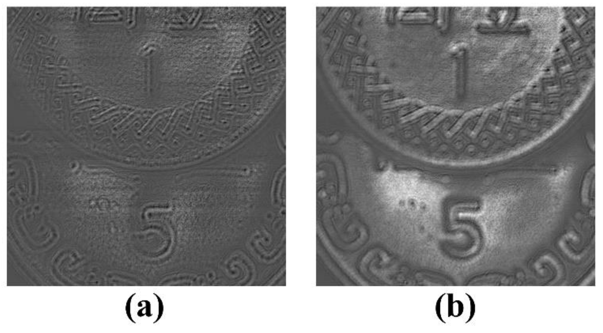
Figure 2 shows the real part and imaginary part of a complex hologram of two coins recorded under the incoherent mode of OSH [57]. The hologram size is pixels with a pixel pitch of . The object distances of the two coins are 90 and 115 mm. The scanned hologram can be digitally reconstructed to an arbitrary plane of distance by
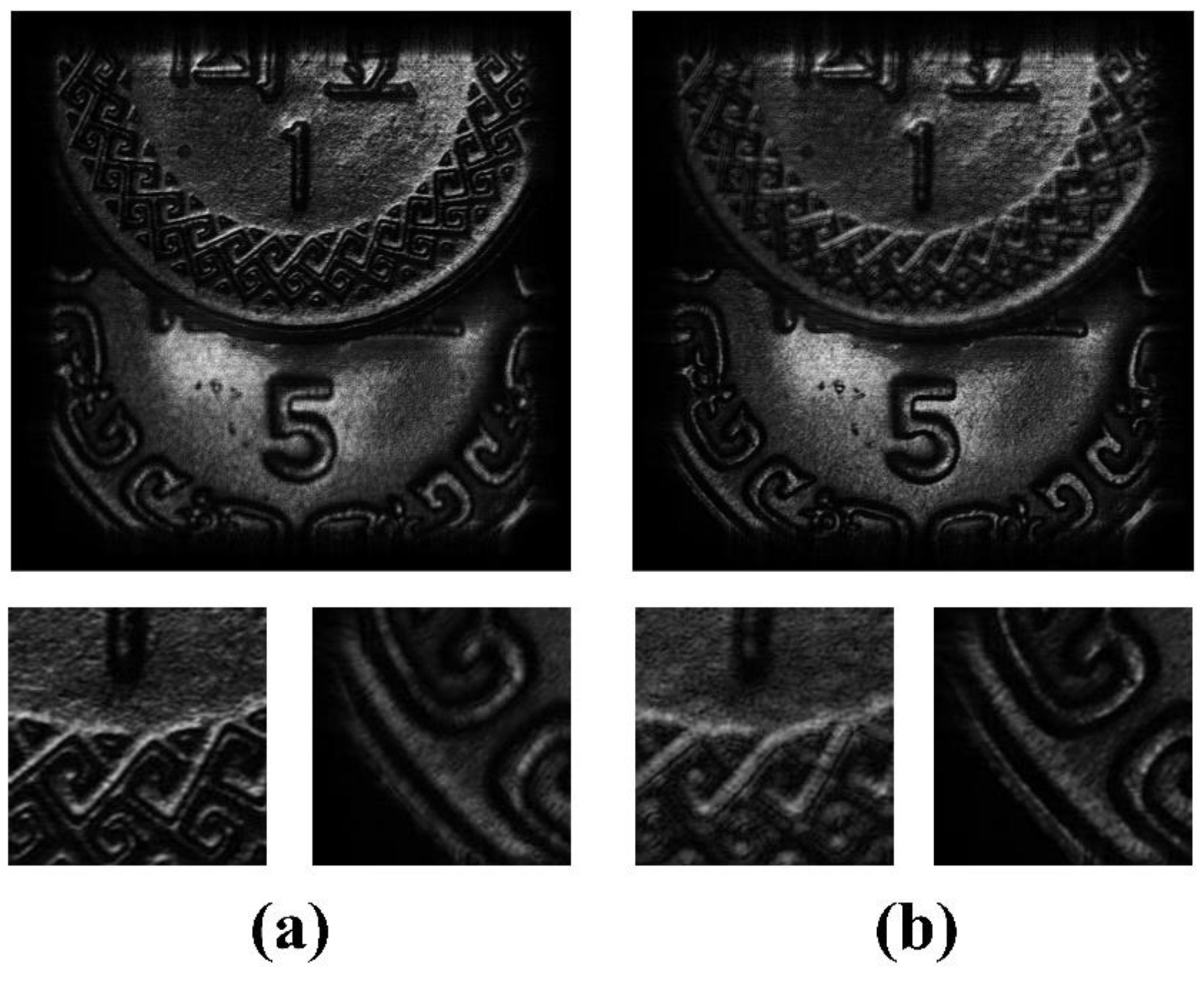
where denotes the convolution involving the and coordinates. Using Equation (5), the hologram shown in Figure 2 has been reconstructed at the planes of the two coins, that is, and . The reconstructed images (the modulus of ) are shown in Figure 3. In Figure 3a, the $1 coin is in focus, while in Figure 3b the $5 coin is in focus.
2.3. Point Spread Function and Pupil Engineering
In the last subsection, the general OSH, for which the interference fringe is formed by a spherical wave and a plane wave, is considered. The point spread function (PSF) of OSH, according to Equation (3), is thus
In reconstruction, the point image is calculated by Fresnel diffraction, that is,
where denotes a Bessel function of the first kind of order 1. Therefore, the Rayleigh resolution of the reconstructed image is , being the same as that in a conventional coherent imaging system. It should be noted that both the coherent mode of OSH and incoherent mode of OSH have the same PSF, regardless of the difference between spatial distributions of and . This is different from conventional imaging systems or conventional DH.
In OSH, the PSF as well as the resolution of the reconstructed image can be modified by using different types of the scanning beam. This can be easily realized by modifying the pupils of the system, such as shown in Figure 1. For example, Indebetouw et al. have proposed to use two spherical waves with opposite curvatures to generate the heterodyne scanning beam [23]. In this way, the fringe density of the scanning beam is double that of conventional OSH, and thus the resolution of the reconstructed image is only half that of conventional OSH. Similarly, resolution enhancement along or the preprocessing of holographic information can be realized by using a spiral phase plate as the pupil [58,59]. In another example, an asymmetry pupil can limit the vertical bandwidth of OSH but retain full horizontal bandwidth [60]. In this way, scanned holograms can be recorded using a fine horizontal sampling rate but a coarse vertical sampling rate without aliasing error. This kind of vertical-bandwidth-limited hologram preserves only the horizontal parallax, but requires a scanning time as well as a data size only about 1/10 those of the full-parallax scanned hologram. Finally, by using a random-phase pupil [19,61], an axicon pupil [62] or a configurable pupil [63], the axial resolution of the OSH is enhanced and thus makes sectional reconstruction possible. In another example, an optical Hilbert transform can be realized by using a quarter-plane pupil in OSH [64].
3. Principle of FINCH
3.1. Setup of FINCH
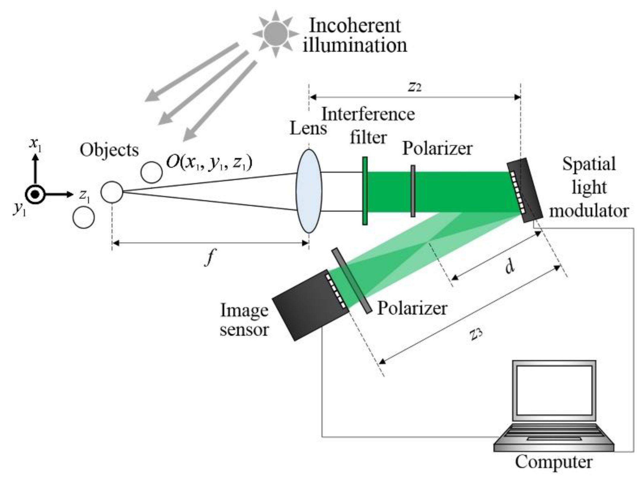
FINCH [33,34,35,36,37,38] is a technique to record holograms of spatially incoherent light with a single-path interferometer. Figure 4 illustrates an optical setup of FINCH. A FINCH system can obtain holograms of objects illuminated by incoherent light with a common-path optical setup without an imaging lens. Incoherent light illuminates objects, and a lens placed between objects and an interference filter collects light diffracted from objects. The interference filter limits the wavelength bandwidth of incoherent light, and then a polarizer generates linear polarized object light with the polarization direction of 45° from the liquid crystal (LC) direction of the SLM. On the SLM, only one of the s- and p-wave components of the incident light is phase-modulated, and the other is not. Therefore, the SLM with a quadratic phase distribution loaded introduces both a uniform phase modulation and quadratic phase shifts to either the s- or p-component of the polarized object light [36,37]. Alternatively, other polarization-sensitive retarders, such as a birefringent crystal or a wave plate, can also be applied to generate two waves that interfere with each other with a single-path optical setup. After the modulation with a SLM, two waves have different wavefronts with different curvature radii and orthogonal polarizations. These waves form an incoherent hologram on the image sensor to reconstruct a 3D object image after passing a linear polarizer with the polarization axis parallel to that used before the SLM. When an object point is set as an incoherent object, a pattern of the FZP is formed on the image sensor plane. The location of the center of a FZP pattern and its fineness depend on the 3D position of a point object, and therefore a hologram recorded by a self-referenced interferometer can reconstruct a 3D image of the incoherent object point. In the case that an arbitrary 3D object is set, the incoherent summation of FZP patterns that are generated from each point on an object is observed with an image sensor. Light diffracted from each object point does not interfere with light diffracted from other object points, and therefore a FINCH system records speckle-less holograms of incoherent 3D objects. In the image-reconstruction process, most of the FINCH systems require in-line configuration and must remove unwanted image components in a hologram, namely, the zeroth-order diffraction wave and conjugate image. FINCH adopts phase-shifting interferometry [65,66] frequently. When adopting temporal phase-shifting interferometry, phase shifts are introduced typically with a SLM [43,46], and phase-shifted incoherent holograms are sequentially recorded. An object wave is extracted from holograms by phase-shifting interferometry, and an incoherent 3D object image is reconstructed by calculating diffraction integrals. As a result, a FINCH system is able to record and reconstruct a speckle-less 3D image of an object illuminated by natural light.
3.2. Mathematical Model of FINCH
According to Figure 4, a wave from an object located at a position passes through a lens with focal length , an interference filter, and a polarizer in sequence. After the polarizer, the object light is modulated by a reflection-type SLM. The s-wave component of the object light is perpendicular to the LC direction and thus is not modulated by the SLM. The p-wave component is parallel to the LC direction and thus suffers a quadratic phase modulation given by
where is the central wavelength after passing through the interference filter, is the focal length of the quadratic phase distribution, and is the phase shift required for phase-shifting interferometry. If the object is a single point, a plane wave and a spherical wave with orthogonal polarization states to each other are generated on the image sensor plane. Therefore, an interference pattern, a FZP pattern, is formed on the image sensor plane by locating a 45° polarizer in front of the image sensor. Considering a 3D object , the image sensor records a pattern , which is expressed as follows [36]:
where is a constant, is the zeroth-order diffraction wave, is the complex conjugate of the integral, and is defined as follows [36]:
where is the distance between the SLM and the lens with the focal length , and is the distance from the SLM to the image sensor. The integral in Equation (9) is the cross-correlation between the object and quadratic phase distribution and is considered as incoherent summation of FZP patterns. The result indicates that the object light is recorded as a Fresnel hologram. After recording the incoherent hologram , the object wave is extracted by the technique of phase-shifting interferometry [67]:
Finally, a 3D image of the object is reconstructed by calculating the Fresnel diffraction integral.
3.3. Point Spread Function
In this subsection, the PSF of FINCH is analyzed. We assume that the object is a point source and is located on the front focal plane of the lens and that . After the calculation of the diffraction integral, the intensity distribution, which refers to the PSF, is reconstructed. According to the theory of Fourier optics, the 2D PSF in the configuration is calculated and is given by the following [37]:
where , is the radius of the recorded interference fringe pattern, and is the total in-plane magnification of the lens and the SLM. has been derived and is given by the following [36]:
The width of the PSF, , is defined as the width of the main lobe of and is
where is the radius of the smallest aperture in the system. In Figure 4, for example, if the radii of the SLM and image sensor are larger than that of the lens that the light is passing through, the smallest aperture is just the radius of the lens. Here, is the same as the PSF of a coherent imaging system, but gives a specific property to FINCH, and recording with the interference of incoherent object waves gives a specific effective PSF for FINCH. is not but when , while the PSF is the same as that of a conventional incoherent imaging system. This is called a violation of the Lagrange invariant, which is seen for a self-reference interferometer using two object waves to obtain an incoherent hologram [68]. Therefore, the magnification of FINCH is higher than that of a conventional imaging system, while it keeps the same functional form of the PSF. If there are two object points on the object plane at a distance of , the two points are apart at a distance of on the reconstructed image plane with the same PSF. By shrinking the distance of the two points , the magnification becomes the same as that in a conventional incoherent imaging system, and, therefore, the width of the PSF is half of that of a coherent system. As a result, the effective PSF becomes narrower by a factor of , which has been derived [37]:
and the effective width of the PSF is as follows:
Therefore, FINCH is regarded as a super-resolution 3D imaging technique.
4. Special Topics and Applications
4.1. Fluorescence Holography
Fluorescence imaging is an essential tool in biological inspection. Because fluorescence holography can provide the 3D distribution of a fluorescent object, it is one of the most important applications of incoherent DH. Fluorescence holography was first demonstrated using OSH by Schilling et al. in 1997 [22], and in 2006, Indebetouw and Zhong demonstrated an OSH-based fluorescence holographic system with transverse resolution of about 1 μm [26]. Furthermore, the use of OSH to 3D locate fluorescent inhomogeneities in turbid media has been demonstrated [69]. The first FINCH-based fluorescence holography was proposed by Rosen and Brooker in 2007 [34]. In 2008, Rosen and Brooker demonstrated a FINCH-based fluorescence holographic microscope for particles [35]. After that, Yanagawa, Abe, and Hayasaki performed 3D mapping of multiple objects with 500 nm diameters simultaneously by using fluorescence holography [42,70]. In recent years, multicolor fluorescence 3D imaging of a biological specimens with a 100 nm resolution has been reported using FINCH with birefringent lenses [38].
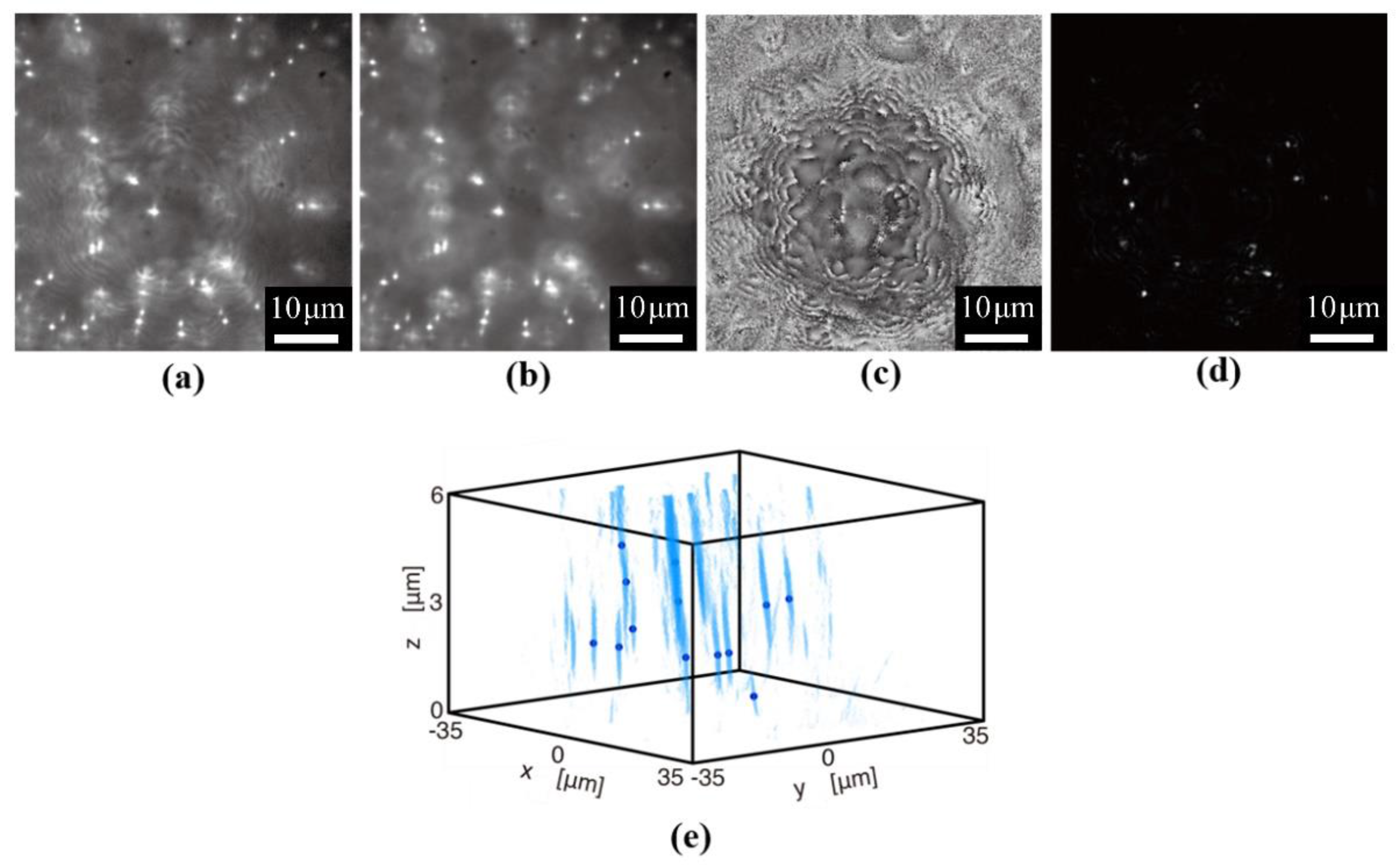
Essentially, the setups of FINCH and OSH can be easily modified to perform fluorescence holography by using an excitation light source and an emission filter, as shown in Figure 5. A self-interference fringe of fluorescence is recorded in FINCH, and thus all properties of FINCH-based fluorescence holography are the same as those in conventional FINCH. Figure 6 shows examples of experimental results with fluorescence digital holographic microscopy. Fluorescent nanoparticles with diameters have been randomly distributed and set as incoherent objects in 3D space. Phase-shifted holograms have been recorded, and the intensity and phase distributions on the image sensor plane have been obtained successfully. By calculating diffraction integrals, reconstructed images focused on arbitrary depths have been obtained. Figure 6d shows an image reconstructed at a specified depth as an example. After that, the 3D mapping of nanoparticles, as shown in Figure 6e, had been conducted with a sequence of the reconstructed images and digital signal processing, such as a space-division matching method [70].
In OSH, a TDFZP of excitation light is generated to scan the fluorescent object. The emittance of the fluorescence is proportional to the irradiance of the excitation scanning light. In addition, the response time of the fluorescence is typically in the order of nanoseconds. Hence the excited fluorescence also oscillates at the modulation frequency, that is, the heterodyne frequency Ω, which is typically between kilohertz and hundreds of megahertz. Finally, the modulated fluorescence is sensed by a detector and demodulated, as in regular OSH. Because fluorescence is very weak, a photomultiplier tube (PMT) or an avalanche photodiode (APD) is usually used as the detector.
4.2. Optical Display of Incoherent Hologram
Incoherent holograms are free of speckle noise upon image reconstruction. Thus, an incoherent hologram should be able to exhibit better reconstructed images than coherent holograms and will be a good candidate for optical display. Recorded incoherent holograms are complex holograms, while the SLMs for optical display are either phase modulation or amplitude modulation. Therefore, the complex incoherent hologram must be converted to a suitable format prior to display. In 2015, Leportier et al. converted a complex incoherent hologram to a binary hologram by an iterative direct binary search algorithm [71]. In 2016, Liu et al. applied a bidirectional error-diffusion method to convert a complex incoherent hologram to a phase-only hologram [31]. Despite the format conversion, there is another important issue in the display of incoherent holograms. As described in Equation (4), the irradiance response is recorded in the incoherent hologram. If the incoherent hologram is directly displayed, the reconstructed field at the object plane is
where is a proportionality constant. The irradiance of the reconstructed field, which is also the quantity the observer detects, will be
In other words, the irradiance of the reconstructed image is distorted, and thus the original contrast of the reconstructed image is incorrect. To solve this problem, the complex incoherent hologram is first digitally propagated to the virtual object plane. At this plane, the field is nearly the same as the irradiance response of the object, . A new field at this plane is generated by
By this way, the nonlinear error as shown in Equation (4) can be compensated for. Finally, the new field is propagated to the hologram plane again and converted to a suitable format, for example, a phase-only hologram.
4.3. Reduction of Scanning Speed and Recorded Data in OSH
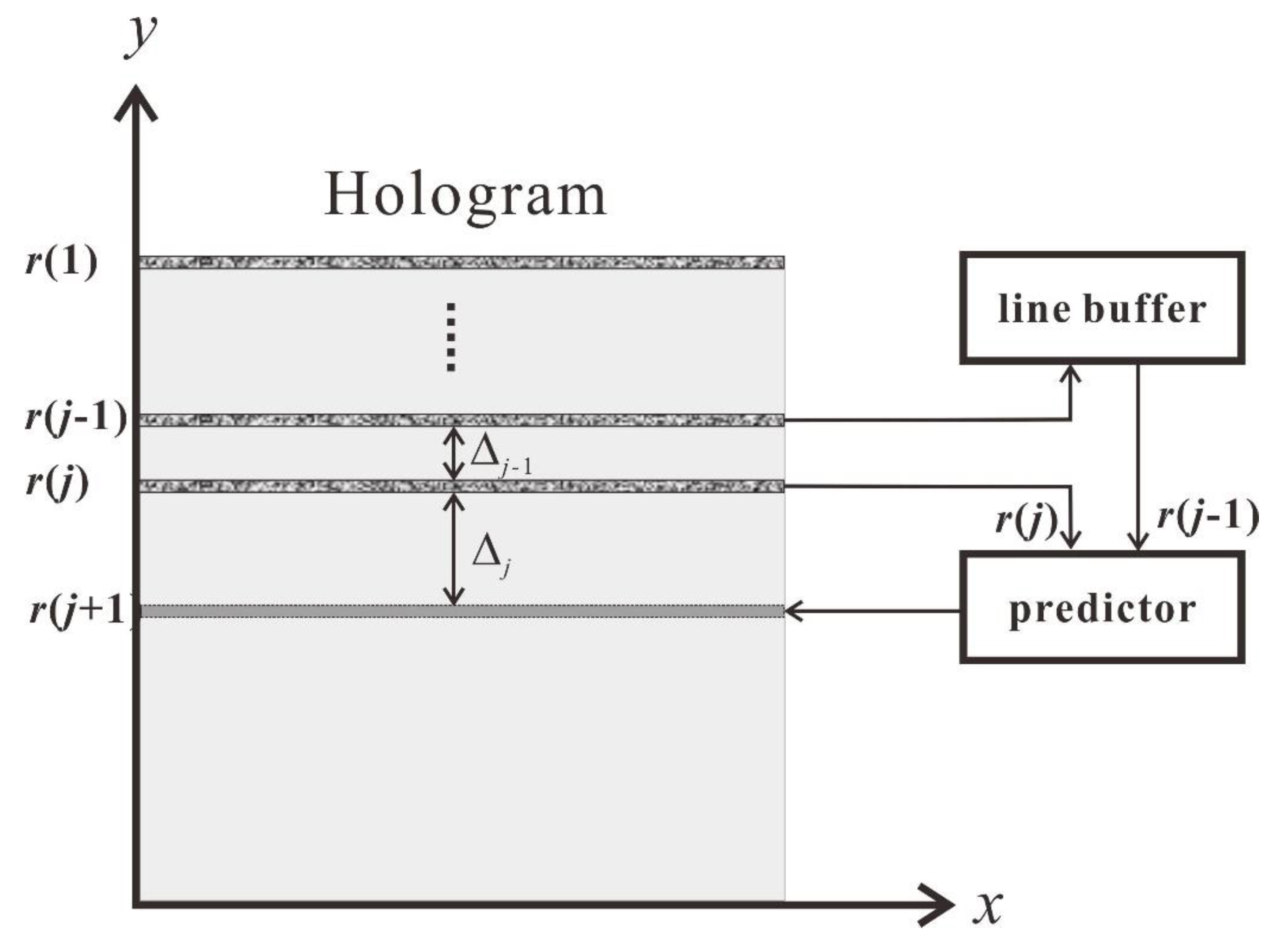
Although OSH has some unique merits, the shortcoming is clear: the demand of 2D raster scanning limits the recording speed of OSH, and thus dynamic optical scanning holography is still a challenge. So far, there have been some trials to shorten the recording time in OSH. The goal is usually to reduce the number of rows of scanning, because the scanning time is proportional to the number of rows, which is related to the vertical pixel pitch. The first trial was proposed by Liu et al., in which a vertical-bandwidth-limited scanned hologram was recorded using a coarse sampling pitch without aliasing [60]. The recording time was reduced to only about 1/10 that of conventional scanning. This method, however, sacrifices the vertical resolution of the whole hologram. For this reason, Tsang et al. proposed a novel technique called adaptive optical scanning holography (AOSH) [72]. As shown in Figure 7, in recording the jth row of the hologram, the row data together with the data from the previous row stored in a line buffer are sent to the predictor. If the variation between and is small, the separation of next scanning, , is increased. In this way, the recording time as well as the size of hologram data can be reduced by up to an order of magnitude. On the basis of a similar concept, not only the vertical pixel pitch but also the horizontal pixel pitch can be adjusted dynamically. In compressive optical scanning holography (COSH) [57,73], only a portion of the hologram pixels of a row are selected and converted into a 1-bit binary representation. Therefore, the resulting hologram data size can be about 1% of that of the original hologram. Recently, Chan et al. proposed subsampled scanning holographic imaging (SuSHI) to record a scanned hologram along a low-density spiral trajectory [74]. Subsequently, the hologram has been reconstructed by a compressed sensing (CS) approach. In this way, both the recording time and the data size can be reduced to up to 4% of that of raster-scanned OSH. The shortcoming of SuSHI, however, is that the CS reconstruction is time-consuming, and thus the scanned holograms cannot be reconstructed on the fly of holographic recording. The use of COSH- or SuSHI-based OSH would make dynamic holographic imaging possible.
4.4. Single-Shot Imager for the Aim of Capturing High-Speed Incoherent 3D Objects
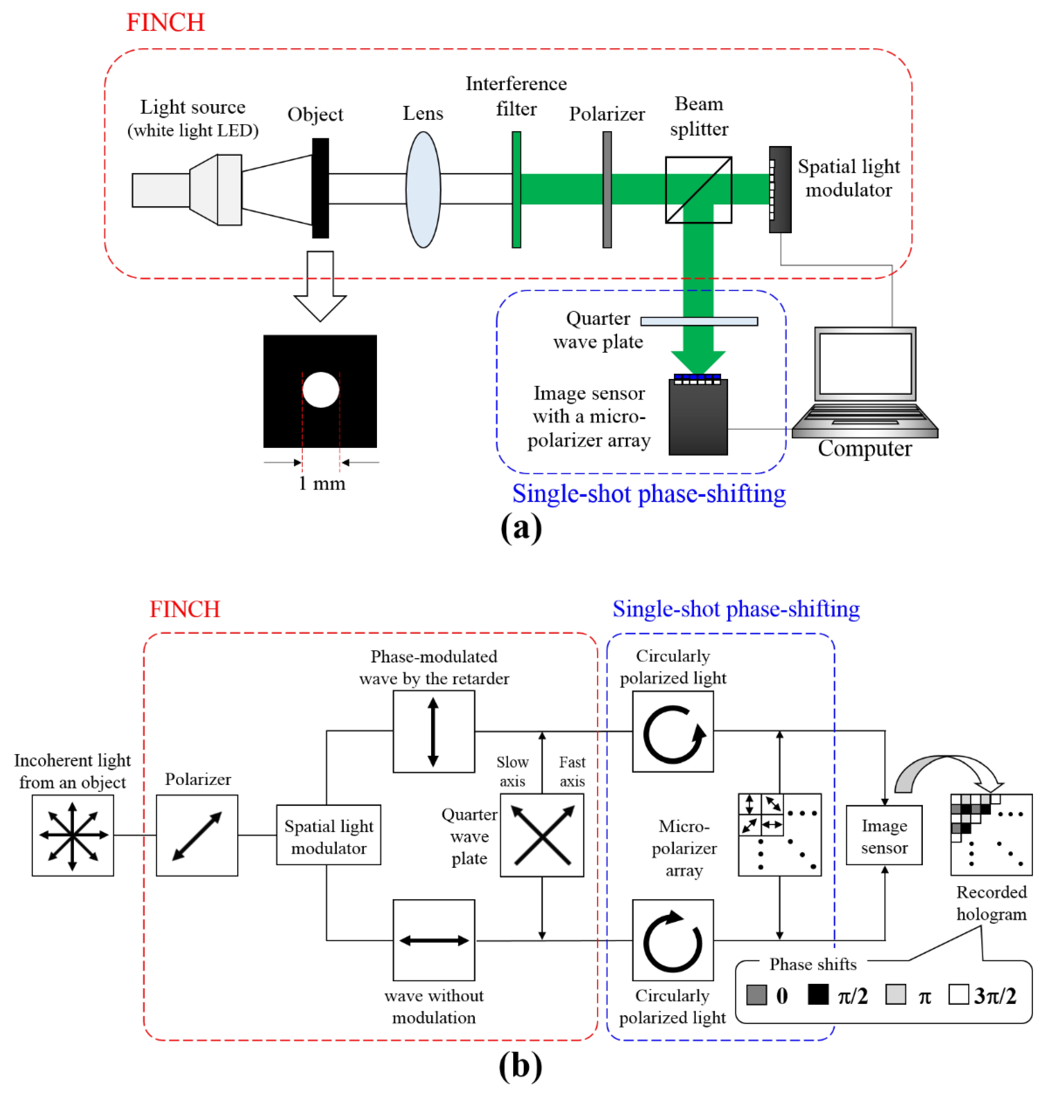
Although FINCH has the ability of spatially high-resolution incoherent 3D imaging, its temporal resolution is not particularly high because of the employment of temporal phase-shifting interferometry. On the other hand, there are intensive requirements for the imaging of dynamics in 3D space in fluorescence and Raman scattering microscopy, machine vision, and other applications. Therefore, single-shot incoherent digital holographic techniques can extend the applicability of incoherent holography. Five types of single-shot incoherent digital holographic techniques have been proposed: off-axis setups with FINCH [75], Michelson interferometry [76], double-focal lens and gratings [77], and an in-line optical system with single-shot phase shifting [78,79]. A Gabor-type configuration is the simplest setup for single-shot 3D imaging. Although zeroth-order diffraction and conjugate images superimpose on the object image, the technique is valid for the case in which objects measured are known or have a simple shape. When applied to arbitrary objects, a technique to separate unwanted images is needed. Kelner and Rosen have proposed a single-shot off-axis incoherent DH system based on FINCH [75]. A Fourier transform hologram has been obtained by passing a SLM twice, and an incoherent 3D image without unwanted images has been reconstructed from a single hologram. Hong and Kim have proposed another single-shot off-axis incoherent DH based on a Michelson interferometry and have demonstrated 3D imaging of multiple LEDs placed at different depths [76]. Quan and co-workers have used a double-focal lens and a grating to generate an off-axis hologram [77]. Their proposal can enable common-path setup and phase modulation without modulating polarization. Tahara et al. have presented single-shot in-line phase-shifting DH and demonstrated the technique for transparent and reflective objects [79]. The technique is composed of the combination of a FINCH system and a single-shot phase-shifting interferometer, as shown in Figure 8. A FINCH system makes use of polarization to shift the phase, and it is easy to combine FINCH and single-shot phase-shifting utilizing polarization. Figure 9 shows experimental results in the case for which the light source is a white light LED and the object measured is a 1 mm aperture. From a recorded single image, multiple-phase-shifted incoherent holograms are obtained with a de-mosaicking process. The complex amplitude distribution of an incoherent object on the image sensor plane is derived with phase-shifting interferometry. After the calculation of diffraction integrals, the focused image of the object is retrieved. It is noted that single-shot in-line phase-shifting DH has an advantage in the space-bandwidth product available for recording an object wave in comparison to off-axis DH.
4.5. Coded Aperture Correlation Holography (COACH)
As a method advancing from FINCH, a remarkable single-path incoherent DH has been recently proposed, called coded aperture correlation holography (COACH) [80]. An optical setup initially proposed for COACH is the same as that of FINCH, as illustrated in Figure 4. In COACH, instead of a quadratic phase distribution, a coded phase-modulation (CPM) distribution is displayed on SLM. Before recording a hologram of an object, multiple phase-shifted holograms of a point object such as a pinhole are recorded. CPM generates a random complex amplitude distribution, and an object wave on the image sensor plane is the PSF of a COACH system. The PSF does not change against the position in the in-plane direction but changes against that in the depth direction. The PSFs of a CPM in each depth are measured in advance to obtain the information of the PSFs in 3D space. After that, incoherent light of an object in 3D space is recorded as multiple phase-shifted holograms, and correlations between PSFs and recorded images are calculated. Cross-correlations are used to obtain a 3D image, because each point in an object cannot be refocused by diffraction integrals, as a result of the random phase distribution of CPM. As a result, a 3D image of incoherent light is reconstructed without calculating diffraction integrals. By the adequate design of CPM and calculations of the cross-correlations, the depth resolution is improved in comparison to FINCH. To improve the depth resolution, one should make the spatial frequency distribution of CPM uniform. With COACH, incoherent 3D imaging [80] and incoherent color 3D imaging with a diffractive lens [81] have been demonstrated. It is worth noting that a diffractive lens is not needed to separate wavelength information by using a holographic technique [67,82]. Moreover, a stack of the PSFs is obtained without interference of incoherent light, and interferenceless incoherent 3D imaging for a scattering object has been performed [83]. In a most recent development, single-shot COACH with space-division multiplexing [84] has been proposed and demonstrated.
5. Conclusions
In this review paper, two techniques of incoherent DH, OSH and FINCH are reviewed. Because OSH is a scanning-type, structured-illumination and single-pixel imaging technique and FINCH is a self-interference-based technique, they exhibit very different features. The features of the two techniques are listed in Table 1 for comparison. Essentially, FINCH is simple and thus can record dynamic holograms easily. However, because a self-interference holographic technique is employed, there is a large bias buildup for complicated objects, thus reducing the dynamic range of the recording device and giving rise to a low signal-to noise ratio in the system [85]. OSH is relatively complicated and slow but has no hard limitation on the recording size and pixel pitch. In addition, OSH can perform filtering on the fly of holographic recording, which is readily compatible to some of the most advanced serial processing systems, such as the fiber-optic-based communication system.
Acknowledgments
Jung-Ping Liu appreciates the financial support from Ministry of Science and Technology of Taiwan under contracts 103-2221-E-035-037-MY3 and 106-2628-E-035-002-MY3. Tatsuki Tahara would like to thank support from the Japan Science and Technology Agency (JST), PRESTO, Grant No. JPMJPR16P8, Japan, and MEXT-Supported Program for the Strategic Research Foundation at Private Universities.
Author Contributions
Conflicts of Interest
The authors declare no conflict of interest.
References
- Watanabe, T.M.; Sato, T.; Gonda, K.; Higuchi, H. Three-dimensional nanometry of vesicle transport in living cells using dual-focus imaging optics. Biochem. Biophys. Res. Commun. 2007, 359, 1–7. [Google Scholar] [CrossRef] [PubMed]
- Tanida, J.; Kumagai, T.; Yamda, K.; Miyatake, S.; Ishida, K.; Morimoto, T.; Kondou, N.; Miyazaki, D.; Ichioka, Y. Thin observation module by bound optics (TOMBO), concept and experimrntalverification. Appl. Opt. 2001, 40, 1806–1819. [Google Scholar] [CrossRef] [PubMed]
- Ozeki, Y.; Umemura, W.; Otsuka, Y.; Satoh, S.; Hashimoto, H.; Sumimura, K.; Nishizawa, N.; Fukui, K.; Itoh, K. High-speed molecular spectral imaging of tissue with stimulated raman scattering. Nat. Photonics 2012, 6, 845–851. [Google Scholar] [CrossRef]
- Horisaki, R.; Ogura, Y.; Aino, M.; Tanida, J. Single-shot phase imaging with a coded aperture. Opt. Lett. 2014, 39, 6466–6469. [Google Scholar] [CrossRef] [PubMed]
- Gabor, D. A new microscopic principle. Nature 1948, 161, 777–778. [Google Scholar] [CrossRef] [PubMed]
- Poon, T.-C. Digital Holography and Three-Dimensional Display; Springer: Berlin, Germany, 2006. [Google Scholar]
- Poon, T.-C.; Liu, J.-P. Introduction to Modern Digital Holography with MATLAB®; Cambridge University Press: Cambridge, UK, 2014. [Google Scholar]
- Indebetouw, G.; Klysubun, P. Imaging through scattering media with depth resolution by use of low-coherence gating in spatiotemporal digital holography. Opt. Lett. 2000, 25, 212–214. [Google Scholar] [CrossRef] [PubMed]
- Lin, Y.-C.; Cheng, C.-J.; Poon, T.-C. Optical sectioning with a low-coherence phase-shifting digital holographic microscope. Appl. Opt. 2011, 50, B25–B30. [Google Scholar] [CrossRef] [PubMed]
- Pham, Q.D.; Hasegawa, S.; Kiire, T.; Barada, D.; Yatagai, T.; Hayasaki, Y. Selectable-wavelength low-coherence digital holography with chromatic phase shifter. Opt. Express 2012, 20, 19744–19756. [Google Scholar] [CrossRef] [PubMed]
- Singh, A.S.G.; Schmoll, T.; Javidi, B.; Leitgeb, R.A. In-line reference-delayed digital holography using a low-coherence light source. Opt. Lett. 2012, 37, 2631–2633. [Google Scholar] [CrossRef] [PubMed]
- Monemhaghdoust, Z.; Montfort, F.; Cuche, E.; Emery, Y.; Depeursinge, C.; Moser, C. Full field vertical scanning in short coherence digital holographic microscope. Opt. Express 2013, 21, 12643–12650. [Google Scholar] [CrossRef] [PubMed]
- Poon, T.-C. Optical Scanning Holography with Matlab; Springer: NewYork, NY, USA, 2007. [Google Scholar]
- Poon, T.-C.; Korpel, A. Optical transfer function of an acousto-optic heterodyning image processor. Opt. Lett. 1979, 4, 317–319. [Google Scholar] [CrossRef] [PubMed]
- Poon, T.-C. Method of two-dimensional bipolar incoherent image processing by acousto-optic two-pupil synthesis. Opt. Lett. 1985, 10, 197–199. [Google Scholar] [CrossRef] [PubMed]
- Poon, T.-C. Scanning holography and two-dimensional image processing by acousto-optic two-pupil synthesis. J. Opt. Soc. Am. A 1985, 2, 521–527. [Google Scholar] [CrossRef]
- Klysubun, P.; Indebetouw, G.; Kim, T.; Poon, T.-C. Accuracy of three-dimensional remote target location using scanning holographic correlation. Opt. Commun. 2000, 184, 357–366. [Google Scholar] [CrossRef]
- Kim, T.; Poon, T.-C.; Indebetouw, G. Depth detection and image recovery in remote sensing by optical scanning holography. Opt. Eng. 2002, 41, 1331–1338. [Google Scholar]
- Poon, T.-C.; Kim, T.; Doh, K. Optical scanning cryptography for secure wireless transmission. Appl. Opt. 2003, 42, 6496–6503. [Google Scholar] [CrossRef] [PubMed]
- Yan, A.; Poon, T.-C.; Hu, Z.; Zhang, J. Optical image encryption using optical scanning and fingerprint keys. J. Mod. Opt. 2016, 63, S38–S43. [Google Scholar] [CrossRef]
- Yan, A.; Wei, Y.; Hu, Z.; Zhang, J.; Tsang, P.W.M.; Poon, T.-C. Optical cryptography with biometrics for multi-depth objects. Sci. Rep. 2017, 7, 12933. [Google Scholar] [CrossRef] [PubMed]
- Schilling, B.W.; Poon, T.-C.; Indebetouw, G.; Storrie, B.; Shinoda, K.; Suzuki, Y.; Wu, M.H. Three-dimensional holographic fluorescence microscopy. Opt. Lett. 1997, 22, 1506–1508. [Google Scholar] [CrossRef] [PubMed]
- Indebetouw, G.; El Maghnouji, A.; Foster, R. Scanning holographic microscopy with transverse resolution exceeding the Rayleigh limit and extended depth of focus. J. Opt. Soc. Am. A 2005, 22, 892–898. [Google Scholar] [CrossRef]
- Indebetouw, G. A posteriori quasi-sectioning of the three-dimensional reconstructions of scanning holographic microscopy. J. Opt. Soc. Am. A 2006, 23, 2657–2661. [Google Scholar] [CrossRef]
- Indebetouw, G.; Tada, Y.; Leacock, J. Quantitative phase imaging with scanning holographic microscopy: An experimental assesment. Biomed. Eng. Online 2006, 5, 63. [Google Scholar] [CrossRef] [PubMed]
- Indebetouw, G.; Zhong, W. Scanning holographic microscopy of three-dimensional fluorescent specimens. J. Opt. Soc. Am. A 2006, 23, 1699–1707. [Google Scholar] [CrossRef]
- Indebetouw, G.; Tada, Y.; Rosen, J.; Brooker, G. Scanning holographic microscopy with resolution exceeding the Rayleigh limit of the objective by superposition of off-axis holograms. Appl. Opt. 2007, 46, 993–1000. [Google Scholar] [CrossRef] [PubMed]
- Lam, E.Y.; Zhang, X.; Vo, H.; Poon, T.-C.; Indebetouw, G. Three-dimensional microscopy and sectional image reconstruction using optical scanning holography. Appl. Opt. 2009, 48, H113–H119. [Google Scholar] [CrossRef] [PubMed]
- Liu, J.-P.; Luo, D.-Z.; Lu, S.-H. Spatial–temporal demodulation technique for heterodyne optical scanning holography. Opt. Lasers Eng. 2015, 68, 42–49. [Google Scholar] [CrossRef]
- Liu, J.-P.; Wang, S.-Y. Stereo-lighting reconstruction of optical scanning holography. IEEE Trans. Ind. Inform. 2016, 12, 1664–1669. [Google Scholar] [CrossRef]
- Liu, J.-P.; Wang, S.-Y.; Tsang, P.W.M.; Poon, T.-C. Nonlinearity compensation and complex-to-phase conversion of complex incoherent digital holograms for optical reconstruction. Opt. Express 2016, 24, 14582–14588. [Google Scholar] [CrossRef] [PubMed]
- Kim, Y.S.; Kim, T.; Woo, S.S.; Kang, H.; Poon, T.-C.; Zhou, C. Speckle-free digital holographic recording of a diffusely reflecting object. Opt. Express 2013, 21, 8183–8189. [Google Scholar] [CrossRef] [PubMed]
- Rosen, J.; Brooker, G. Digital spatially incoherent fresnel holography. Opt. Lett. 2007, 32, 912–914. [Google Scholar] [CrossRef] [PubMed]
- Rosen, J.; Brooker, G. Fluorescence incoherent color holography. Opt. Express 2007, 15, 2244–2250. [Google Scholar] [CrossRef] [PubMed]
- Rosen, J.; Brooker, G. Non-scanning motionless fluorescence three-dimensional holographic microscopy. Nat. Photonics 2008, 2, 190–195. [Google Scholar] [CrossRef]
- Brooker, G.; Siegel, N.; Wang, V.; Rosen, J. Optimal resolution in fresnel incoherent correlation holographic fluorescence microscopy. Opt. Express 2011, 19, 5047–5062. [Google Scholar] [CrossRef] [PubMed]
- Rosen, J.; Siegel, N.; Brooker, G. Theoretical and experimental demonstration of resolution beyond the Rayleigh limit by finch fluorescence microscopic imaging. Opt. Express 2011, 19, 26249–26268. [Google Scholar] [CrossRef] [PubMed]
- Siegel, N.; Lupashin, V.; Storrie, B.; Brooker, G. High-magnification super-resolution finch microscopy using birefringent crystal lens interferometers. Nat. Photonics 2016, 10, 802–808. [Google Scholar] [CrossRef] [PubMed]
- Bryngdahl, O.; Lohmann, A. One-dimensional holography with spatially incoherent light. J. Opt. Soc. Am. 1968, 58, 625–628. [Google Scholar] [CrossRef]
- Itoh, K.; Inoue, T.; Yoshida, T.; Ichioka, Y. Interferometric supermultispectral imaging. Appl. Opt. 1990, 29, 1625–1630. [Google Scholar] [CrossRef] [PubMed]
- Kim, M.K. Full color natural light holographic camera. Opt. Express 2013, 21, 9636–9642. [Google Scholar] [CrossRef] [PubMed]
- Yanagawa, T.; Abe, R.; Hayasaki, Y. Three-dimensional mapping of fluorescent nanoparticles using incoherent digital holography. Opt. Lett. 2015, 40, 3312–3315. [Google Scholar] [CrossRef] [PubMed]
- Watanabe, K.; Nomura, T. Recording spatially incoherent fourier hologram using dual channel rotational shearing interferometer. Appl. Opt. 2015, 54, A18–A22. [Google Scholar] [CrossRef] [PubMed]
- Obara, M.; Yoshimori, K. 3D spatial resolution and spectral resolution of interferometric 3D imaging spectrometry. Appl. Opt. 2016, 55, 2489–2497. [Google Scholar] [CrossRef] [PubMed]
- Naik, D.N.; Pedrini, G.; Takeda, M.; Osten, W. Spectrally resolved incoherent holography: 3D spatial and spectral imaging using a mach-zehnder radial-shearing interferometer. Opt. Lett. 2014, 39, 1857–1860. [Google Scholar] [CrossRef] [PubMed]
- Wan, Y.; Man, T.; Wang, D. Incoherent off-axis Fourier triangular color holography. Opt. Express 2014, 22, 8565–8573. [Google Scholar] [CrossRef] [PubMed]
- Lohmann, A.W. Wavefront reconstruction for incoherent objects. J. Opt. Soc. Am. 1965, 55, 1555_1-1556. [Google Scholar] [CrossRef]
- Sirat, G.; Psaltis, D. Conoscopic holography. Opt. Lett. 1985, 10, 4–6. [Google Scholar] [CrossRef] [PubMed]
- Kim, H.; Kim, Y.S.; Kim, T. Full-color optical scanning holography with common red, green, and blue channels [invited]. Appl. Opt. 2016, 55, A17–A21. [Google Scholar] [CrossRef] [PubMed]
- Poon, T.-C.; Kim, T.; Indebetouw, G.; Schilling, B.W.; Wu, M.H.; Shinoda, K.; Suzuki, Y. Twin-image elimination experiments for three-dimensional images in optical scanning holography. Opt. Lett. 2000, 25, 215–217. [Google Scholar] [CrossRef] [PubMed]
- Rosen, J.; Indebetouw, G.; Brooker, G. Homodyne scanning holography. Opt. Express 2006, 14, 4280–4285. [Google Scholar] [CrossRef] [PubMed]
- Swoger, J.; Martinez-Corral, M.; Huisken, J.; Stelzer, E.H.K. Optical scanning holography as a technique for high-resolution three-dimensional biological microscopy. J. Opt. Soc. Am. A 2002, 19, 1910–1918. [Google Scholar] [CrossRef]
- Poon, T.-C.; Indebetouw, G. Three-dimensional point spread functions of an optical heterodyne scanning image processor. Appl. Opt. 2003, 42, 1485–1492. [Google Scholar] [CrossRef] [PubMed]
- Liu, J.-P. Spatial coherence analysis for optical scanning holography. Appl. Opt. 2015, 54, A59–A66. [Google Scholar] [CrossRef] [PubMed]
- Liu, J.-P.; Guo, C.-H.; Hsiao, W.-J.; Poon, T.-C.; Tsang, P.W.M. Coherence experiments in single-pixel digital holography. Opt. Lett. 2015, 40, 2366–2369. [Google Scholar] [CrossRef] [PubMed]
- Indebetouw, G.; Klysubun, P.; Kim, T.; Poon, T.-C. Imaging properties of scanning holographic microscopy. J. Opt. Soc. Am. A 2000, 17, 380–390. [Google Scholar] [CrossRef]
- Tsang, P.W.M.; Liu, J.-P.; Poon, T.-C. Compressive optical scanning holography. Optica 2015, 2, 476–483. [Google Scholar] [CrossRef]
- Chen, N.; Ren, Z.; Ou, H.; Lam, E.Y. Resolution enhancement of optical scanning holography with a spiral modulated point spread function. Photonics Res. 2016, 4, 1–6. [Google Scholar] [CrossRef]
- Pan, Y.; Jia, W.; Yu, J.; Dobson, K.; Zhou, C.; Wang, Y.; Poon, T.-C. Edge extraction using a time-varying vortex beam in incoherent digital holography. Opt. Lett. 2014, 39, 4176–4179. [Google Scholar] [CrossRef] [PubMed]
- Liu, J.-P.; Lee, C.-C.; Lo, Y.-H.; Luo, D.-Z. Vertical-bandwidth-limited digital holography. Opt. Lett. 2012, 37, 2574–2576. [Google Scholar] [CrossRef] [PubMed]
- Xin, Z.; Dobson, K.; Shinoda, Y.; Poon, T.-C. Sectional image reconstruction in optical scanning holography using a random-phase pupil. Opt. Lett. 2010, 35, 2934–2936. [Google Scholar] [CrossRef] [PubMed]
- Indebetouw, G.; Zhong, W.; Chamberlin-Long, D. Point-spread function synthesis in scanning holographic microscopy. J. Opt. Soc. Am. A 2006, 23, 1708–1717. [Google Scholar] [CrossRef]
- Ou, H.; Poon, T.-C.; Wong, K.K.Y.; Lam, E.Y. Enhanced depth resolution in optical scanning holography using a configurable pupil. Photonics Res. 2014, 2, 64–70. [Google Scholar] [CrossRef]
- Poon, T.-C.; Doh, K.B. On the theory of optical Hilbert transform for incoherent object. Opt. Express 2007, 15, 3006–3011. [Google Scholar] [CrossRef] [PubMed]
- Bruning, J.H.; Herriott, D.R.; Gallagher, J.; Rosenfeld, D.; White, A.; Brangaccio, D. Digital wavefront measuring interferometer for testing optical surfaces and lenses. Appl. Opt. 1974, 13, 2693–2703. [Google Scholar] [CrossRef] [PubMed]
- Yamaguchi, I.; Zhang, T. Phase-shifting digital holography. Opt. Lett. 1997, 22, 1268–1270. [Google Scholar] [CrossRef] [PubMed]
- Tahara, T.; Mori, R.; Arai, Y.; Takaki, Y. Four-step phase-shifting digital holography simultaneously sensing dual-wavelength information using a monochromatic image sensor. J. Opt. 2015, 17, 125707. [Google Scholar] [CrossRef]
- Rosen, J.; Kelner, R. Modified lagrange invariants and their role in determining transverse and axial imaging resolutions of self-interference incoherent holographic systems. Opt. Express 2014, 22, 29048–29066. [Google Scholar] [CrossRef] [PubMed]
- Indebetouw, G.; Kim, T.; Poon, T.-C.; Schilling, B.W. Three-dimensional location of fluorescent inhomogeneities in turbid media by scanning heterodyne holography. Opt. Lett. 1998, 23, 135–137. [Google Scholar] [CrossRef] [PubMed]
- Abe, R.; Hayasaki, Y. Holographic fluorescence mapping using space-division matching method. Opt. Commun. 2017, 401, 35–39. [Google Scholar] [CrossRef]
- Leportier, T.; Park, M.C.; Kim, Y.S.; Kim, T. Converting optical scanning holograms of real objects to binary fourier holograms using an iterative direct binary search algorithm. Opt. Express 2015, 23, 3403–3411. [Google Scholar] [CrossRef] [PubMed]
- Tsang, P.W.M.; Poon, T.-C.; Liu, J.-P. Adaptive optical scanning holography. Sci. Rep. 2016, 6, 21636. [Google Scholar] [CrossRef] [PubMed]
- Tsang, P.W.M.; Poon, T.-C.; Liu, J.-P.; Kim, T.; Kim, Y.S. Low complexity compression and speed enhancement for optical scanning holography. Sci. Rep. 2016, 6, 34724. [Google Scholar] [CrossRef] [PubMed]
- Chan, A.C.S.; Tsia, K.K.; Lam, E.Y. Subsampled scanning holographic imaging (SuSHI) for fast, non-adaptive recording of three-dimensional objects. Optica 2016, 3, 911–917. [Google Scholar] [CrossRef]
- Kelner, R.; Rosen, J. Spatially incoherent single channel digital fourier holography. Opt. Lett. 2012, 37, 3723–3725. [Google Scholar] [CrossRef] [PubMed]
- Hong, J.; Kim, M.K. Single-shot self-interference incoherent digital holography using off-axis configuration. Opt. Lett. 2013, 38, 5196–5199. [Google Scholar] [CrossRef] [PubMed]
- Quan, X.; Matoba, O.; Awatsuji, Y. Single-shot incoherent digital holography using a dual-focusing lens with diffraction gratings. Opt. Lett. 2017, 42, 383–386. [Google Scholar] [CrossRef] [PubMed]
- Tahara, T.; Arai, Y. Hologram Recording Apparatus and Hologram Recording Method. Japanese Patent Application P2013-127829, 18 June 2013. [Google Scholar]
- Tahara, T.; Kanno, T.; Arai, Y.; Ozawa, T. Single-shot phase-shifting incoherent digital holography. J. Opt. 2017, 19, 065705. [Google Scholar] [CrossRef]
- Vijayakumar, A.; Kashter, Y.; Kelner, R.; Rosen, J. Coded aperture correlation holography—A new type of incoherent digital holograms. Opt. Express 2016, 24, 12430–12441. [Google Scholar] [CrossRef] [PubMed]
- Vijayakumar, A.; Rosen, J. Spectrum and space resolved 4D imaging by coded aperture correlation holography (COACH) with diffractive objective lens. Opt. Lett. 2017, 42, 947–950. [Google Scholar] [CrossRef] [PubMed]
- Tahara, T.; Otani, R.; Omae, K.; Gotohda, T.; Arai, Y.; Takaki, Y. Multiwavelength digital holography with wavelength-multiplexed holograms and arbitrary symmetric phase shifts. Opt. Express 2017, 25, 11157–11172. [Google Scholar] [CrossRef] [PubMed]
- Vijayakumar, A.; Rosen, J. Interferenceless coded aperture correlation holography—A new technique for recording incoherent digital holograms without two-wave interference. Opt. Express 2017, 25, 13883–13896. [Google Scholar] [CrossRef] [PubMed]
- Ratnam Rai, M.; Vijayakumar, A.; Rosen, J. Single camera shot interferenceless coded aperture correlation holography. Opt. Lett. 2017, 42, 3992–3995. [Google Scholar] [CrossRef] [PubMed]
- Poon, T.-C. Scan-free three-dimensional imaging. Nat. Photonics 2008, 2, 131–132. [Google Scholar] [CrossRef]
Figure 1.
Schematic setup of optical scanning holography (OSH). EOM: electro-magnetic modulator; PBS: polarizing beamsplitter; M’s: mirrors; BEs: beam expanders; HWP: half-wave plate; L’s: lenses; and are the focal lengths of lenses L2 and L3, respectively; PDs: photodetectors; BPF@Ω: band-pass filter tuned at frequency Ω.

Figure 2.
Hologram of two coins recorded by optical scanning holography (OSH): (a) real part, and (b) imaginary part. (Reproduced with permission from [57], OSA publishing, 2015).
Figure 2.
Hologram of two coins recorded by optical scanning holography (OSH): (a) real part, and (b) imaginary part. (Reproduced with permission from [57], OSA publishing, 2015).

Figure 3.
Reconstructed image at (a) , and (b) . The larger figures show the whole field of view, while the small figures are the zoom-in of selected regions (Reproduced with permission from [57], OSA publishing, 2015).
Figure 3.
Reconstructed image at (a) , and (b) . The larger figures show the whole field of view, while the small figures are the zoom-in of selected regions (Reproduced with permission from [57], OSA publishing, 2015).

Figure 4.
An optical setup of Fresnel incoherent correlation holography (FINCH).

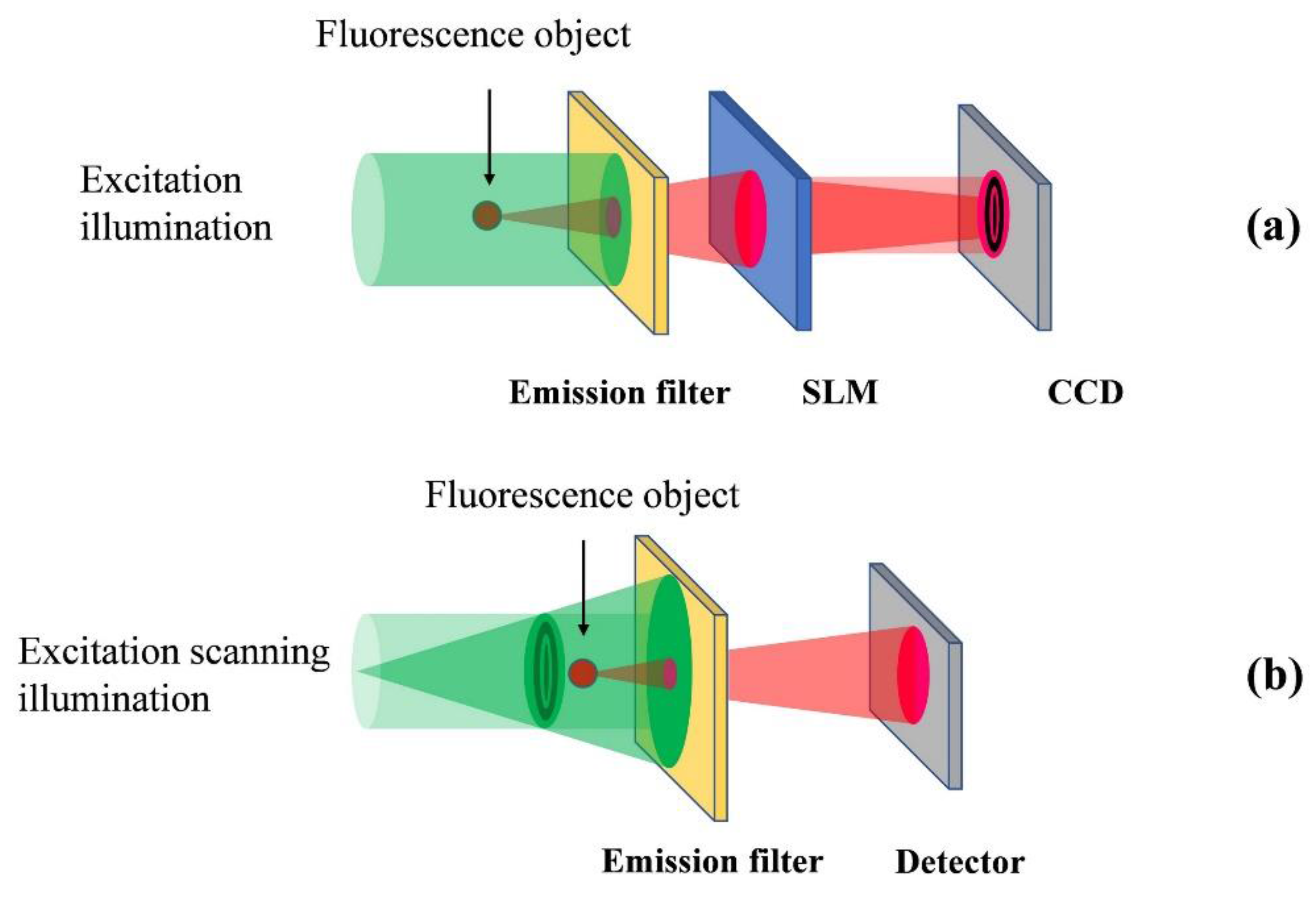
Figure 5.
Setups of fluorescence holography: (a) Fresnel incoherent correlation holography (FINCH), and (b) optical scanning holography (OSH).
Figure 5.
Setups of fluorescence holography: (a) Fresnel incoherent correlation holography (FINCH), and (b) optical scanning holography (OSH).

Figure 6.
Experimental results of fluorescence holography. (a) One of the phase-shifted holograms, (b) intensity, and (c) phase distributions on the image sensor plane. (d) Reconstructed image on a specified depth, and (e) three-dimensional (3D) mapping of fluorescent nanoparticles with incoherent digital holographic microscopy.

Figure 7.
Schematic of the concept of adaptive optical scanning holography (AOSH).

Figure 8.
Single-shot in-line phase-shifting digital holography (DH) with Fresnel incoherent correlation holography (FINCH). (a) Schematic of a constructed optical setup. (b) Transitions of the states of polarizations.
Figure 8.
Single-shot in-line phase-shifting digital holography (DH) with Fresnel incoherent correlation holography (FINCH). (a) Schematic of a constructed optical setup. (b) Transitions of the states of polarizations.

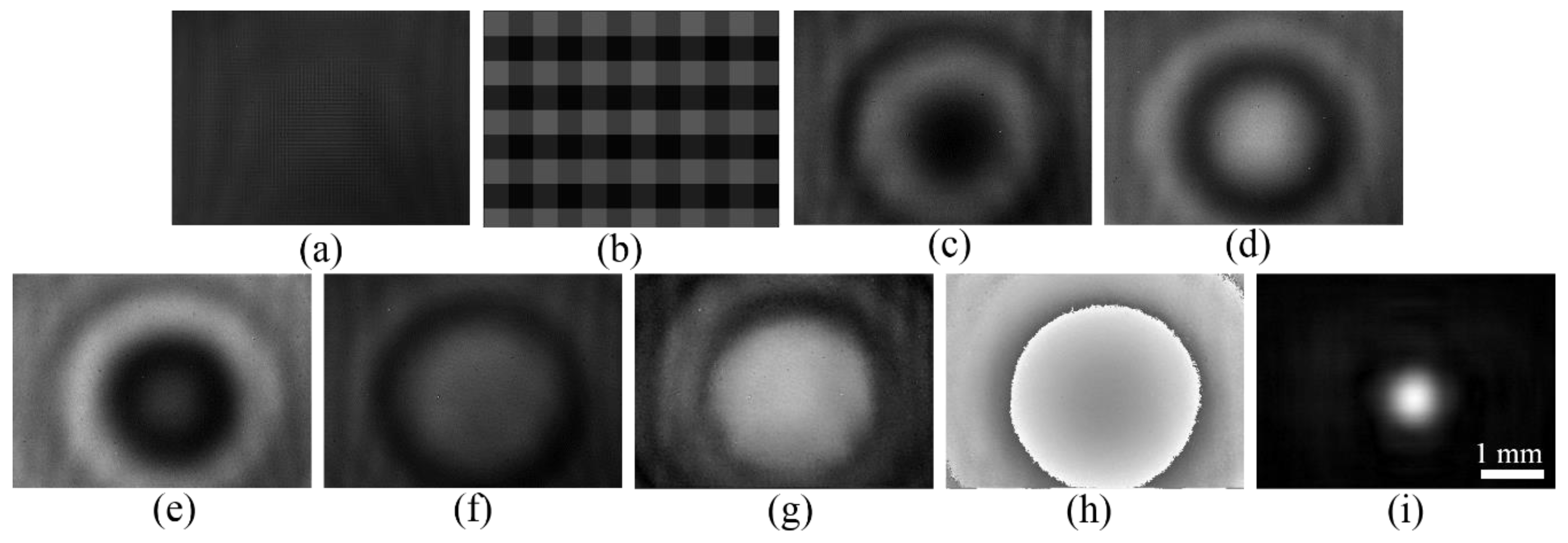
Figure 9.
Experimental results. (a) Recorded hologram; (b) magnified image of a part of (a) four phase-shifted holograms, which are generated from (a), with (c) 0, (d) , (e) , and (f) phase shifts; (g) amplitude, and (h) phase images on the image sensor plane, which are extracted by phase-shifting interferometry; (i) reconstructed image of a 1 mm aperture object illuminated by incoherent light.


Table 1.
Comparison of optical scanning holography (OSH) and Fresnel incoherent correlation holography (FINCH).
Table 1.
Comparison of optical scanning holography (OSH) and Fresnel incoherent correlation holography (FINCH).
| OSH | FINCH | |
|---|---|---|
| 1. Field of view | Large 1 | Small |
| 2. Pixel pitch | Very small 1 | Small |
| 3. System variety 2 | High | Low |
| 4. Recording time | Slow | Fast |
| 5. Imaging by natural light | No 3 | Yes 4 |
| 6. System complexity | High | Low |
1 The field of view and pixel pitch in OSH depends on the scanning setup. 2 This means that the system can be adapted to realize different applications of imaging. 3 Active scanning imaging. 4 Passive imaging.
© 2018 by the authors. Licensee MDPI, Basel, Switzerland. This article is an open access article distributed under the terms and conditions of the Creative Commons Attribution (CC BY) license (http://creativecommons.org/licenses/by/4.0/).
Share and Cite
MDPI and ACS Style
Liu, J.-P.; Tahara, T.; Hayasaki, Y.; Poon, T.-C. Incoherent Digital Holography: A Review. Appl. Sci. 2018, 8, 143. https://doi.org/10.3390/app8010143
AMA Style
Liu J-P, Tahara T, Hayasaki Y, Poon T-C. Incoherent Digital Holography: A Review. Applied Sciences. 2018; 8(1):143. https://doi.org/10.3390/app8010143
Chicago/Turabian StyleLiu, Jung-Ping, Tatsuki Tahara, Yoshio Hayasaki, and Ting-Chung Poon. 2018. "Incoherent Digital Holography: A Review" Applied Sciences 8, no. 1: 143. https://doi.org/10.3390/app8010143
Note that from the first issue of 2016, this journal uses article numbers instead of page numbers. See further details here.