Message Collision Avoidance Protocols for Detecting Stray Nodes in a Scuba Diving Group Using Ultrasonic Multi-Hop Message Communication

Information Systems Science Major, Graduate School of Engineering, Soka University, 1-236 Tangi-cho, Hachioji 192-8577, Japan
*
Author to whom correspondence should be addressed.
Appl. Sci. 2018, 8(1), 24; https://doi.org/10.3390/app8010024
Submission received: 30 October 2017
/
Revised: 21 December 2017
/
Accepted: 22 December 2017
/
Published: 25 December 2017
(This article belongs to the Special Issue Underwater Acoustics, Communications and Information Processing)
Abstract
:Recent years have seen a growing interest in underwater communication and some progress has been made in this area. However, underwater communication is still immature compared with terrestrial communication. A prime reason for this is that the underwater environment is intrinsically not suitable for propagation of electric waves. Instead, ultrasonic waves are mainly used for underwater communication. Since ultrasonic waves cannot provide sufficient communication speed or capacity, they cannot use existing network technologies, which assume use of radio waves. In particular, communication in shallow water is still an uncharted territory. Few communication technologies are employed in environments where people enjoy scuba diving. This paper addresses problems faced by recreational scuba divers. It proposes constructing an ad hoc mesh-shaped network between divers within a group and use ultrasonic waves as transmission media in order to enable the detection of a stray diver. It also proposes a communication protocol in which messages are relayed in multiple hops, and a message collision avoidance method, which is intended to reduce the rate of packet loss caused by message propagation delay. We have implemented the proposed methods in a network simulator, and compared them with an existing communication method that has no message collision avoidance function, in terms of the packet loss rate, the stray driver detection rate, and the rate of the ability to communicate in multiple hops.
1. Introduction
Underwater communication is required in a wide range of fields, such as marine environment survey, seabed resource survey, and fishery. However, there are few services that are intended for short-range communication. This paper focuses on an underwater short-range communication service for scuba divers. Underwater communication technology is expected to make recreational diving more enjoyable and safer. Currently, it is considered difficult for scuba divers to make verbal communication, and thus they usually use hand signals to transmit a variety of information. However, unless there is good visibility, hand signals cannot work and scuba divers often find it hard to notice a group member going astray or suffering a change in his/her physical condition. A feature of scuba diving is that even a small problem can lead to a graver accident than in other types of sport or entertainment. It is reported that divers feel a great danger when a member of the group he or she is leading goes astray [1]. Safer scuba diving would be possible if there was an electronic terminal for underwater use that enables divers to communicate with each other and that alerts other group members when a member strays far away from the group.
Underwater communication poses more demanding technical challenges than terrestrial communication. A number of studies and surveys have been undertaken to build an environment for smooth communication [2,3,4,5,6,7]. Since high-frequency radio waves are heavily absorbed in water, ultrasonic waves are normally used for underwater communication. However, the bandwidth of ultrasonic waves is so narrow that channel contention can occur frequently, resulting in high packet loss.
The present paper proposes a multi-hop message communication protocol that allows scuba divers to communicate with other divers in a group using ultrasonic waves so that they can check whether any member has gone astray. It also discusses the characteristics of underwater propagation attenuation and proposes a method of avoiding channel contention in underwater communication. This method is compared with a method that has no function to avoid message collisions. This paper is organized as follows. Section 2 presents underwater communication technology and technology for avoiding contention in communication involving multi-access to the transmission medium. This section also identifies the position of the present research. Section 3 gives some examples of group management used in scuba diving. Section 4 proposes message communication protocols designed for underwater communication. Section 5 describes the experimental system we have developed to implement and evaluate the proposed protocols. Section 6 discusses evaluation results. Finally, Section 7 gives the conclusions and future issues.
2. Existing Technologies and the Position of the Present Research
This section presents currently used underwater communication technologies, and describes advantages and drawbacks of technologies used to avoid contention in communication involving multi-access to the transmission medium. It also identifies the position of the present research.
2.1. Inter-Diver Communication Technology
Yamagata Casio Co., Ltd. (Higashine, Yamagata, Japan) sells a compact inter-diver communication tool—an underwater transceiver called “Logosease” [8]. It uses ultrasonic waves and bone-conduction speakers and microphones to allow verbal communication in water.
While this terminal allows verbal conversation, it cannot recognize how far apart the nodes involved are. Therefore, even if a user goes astray, other users cannot recognize it. There are other methods for underwater verbal communication but none of them can recognize the distances between nodes, and thus cannot detect stray nodes.
2.2. Technologies for Avoiding Contention in Multi-Access to the Transmission Medium
2.2.1. CSMA/CA (Carrier Sense Multiple Access with Collision Avoidance)
CSMA/CA is a collision avoidance protocol adopted in a wireless communication specification, IEEE 802.11 [9]. When a terminal senses that other terminals are not communicating, it begins to communicate after a waiting time consisting of the IFS (interframe space) and a random back off time. The IFS can be adjusted based on the processing performance of the devices involved and the priority of the particular message. There are different types of IFS: SIFS (short interframe space), which is applied to high-priority messages, and DIFS (DFC interframe space), which is used to send ordinary data. The value of SIFS is smaller than that of DIFS. CSMA/CA avoids a collision by allowing a terminal to initiate communication after an elapse of the back off time. This can be used in both access point mode and ad hoc mode communication. However, the propagation delay is so long in ultrasonic communication that carrier sensing often fails to detect the starts of communication by other terminals. This means that many terminals (known as hidden terminals) go unnoticed, resulting in channel contention and packet loss.
2.2.2. CSMA/CA with Ack and CSMA/CA with RTS/CTS
CSMA/CA with Ack is a protocol in which the access point (AP) that has received a data transmission frame always acknowledges the receipt of the frame by sending an Ack to the sending terminal. Sending of this Ack message lets other terminals know that the channel has been cleared and is now available. However, in an ad-hoc mode broadcast communication, no Ack message is returned. Therefore, no retransmission can be made.
CSMA/CA with RTS/CTS has been devised to solve the problem of hidden terminals in a LAN using CSMA/CA. The AP uses a data transmission request message, called RTS (request to send), and a transmission permission message, called CTS (clear to send), to give or not to give each terminal permission to send packets. However, in an environment in which messages are transmitted in multiple hops, nodes that cannot directly communicate with the AP cannot receive RTS/CTS messages from the AP.
DACAP [10] is a version of CSMA/CA with RTS/CTS designed for underwater communication. This protocol was proposed by Borja Peleato. It utilizes a timer whose value is adapted to underwater propagation delay and low transmission speed to avoid a collision. However, being a version of RTS/CTS, it is not usable in a multi-hop environment. There are other studies on RTS/CTS-based technologies designed for underwater use, but none of them assume use in a multi-hop environment [11]. These protocols are adopted in access point mode communication. They cannot be used in ad-hoc mode communication because there is no terminal that controls message transmission.
2.3. Position of the Present Research
This paper presents a message communication protocol for detecting stray nodes in an ad-hoc network for scuba divers. Protocols that rely on CSMA/CA only cannot avoid contention sufficiently with carrier sensing because the propagation delay of ultrasonic communication is extremely long. A feature of the proposed protocol is that it avoids message collisions arising from this contention by using the application layer to stagger message occurrence time.
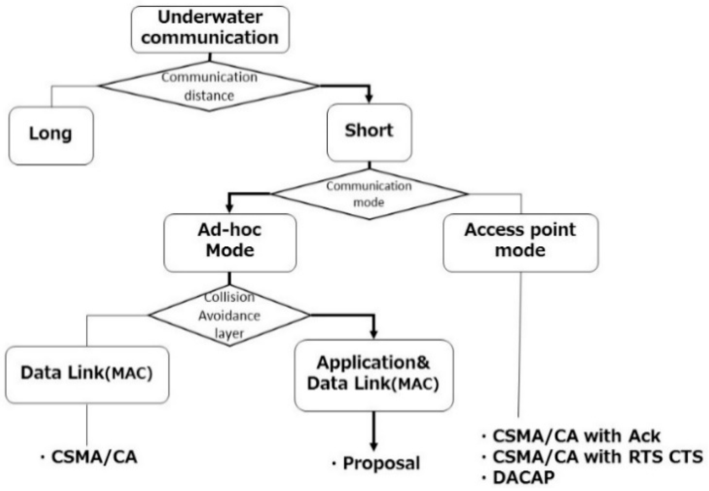
Communication via a single channel is assumed. A feature of underwater communication is that the higher the signal frequency, the greater the signal is attenuated, rendering the usable bandwidth extremely narrow. If multiple channels are used for data transmission, the bandwidth of each channel becomes so narrow that the amount of data that can be sent becomes small, which in turn reduces transmission speed. Protocols relying on the media access control (MAC) layer described in Section 2.2 cause such a long transmission delay that it is difficult to avoid contention. Therefore, they cannot achieve efficient underwater communication in an ad-hoc network. This paper proposes a contention avoidance method that relies on the application layer. This method decreases channel contention by varying message transmission timing according to the message type. An ideal protocol for use in scuba diving is one that permits communication with stray nodes so that these nodes will be able to rejoin the diver group they belong to. Therefore, multi-hop message transmission is used. Figure 1 shows the position of the proposed transmission medium multi-access contention avoidance technology.
3. Group Management in Scuba Diving
Scuba diving is generally conducted in a group. Therefore, safer diving can be ensured by managing information about group members.
Each diver has a terminal that can operate underwater. Each terminal has a node ID and a group ID for identification. In an ordinary recreational diving, divers make up a group and move together. The instructor is provided with a group management capability and is alerted when any group member goes out of the permitted area. This situation is illustrated in Figure 2. In Figure 2, Diver C is astray. The leader communicates with other divers at certain intervals.
When a member goes astray, underwater communication enables the leader node to detect the incident immediately, thereby preventing a serious accident from happening. Detailed operations of this protocol are presented in Section 4.
4. Stray Node Detection Protocol and Method of Avoiding Message Collision
We propose a detection method. The area covered by each transmitter is limited by its transmission power. Any node that goes out of that area is regarded as a stray node. As shown in Figure 3, the transmission power of each node is adjusted so that the radius of the area covered by its transmitter is r. Nodes are classified into one leader node and normal nodes. Let r′ be the distance between a normal node and the leader node. If r ˂ r′, that normal node is regarded as a stray node.
Normal nodes located within a spherical area of radius r with the leader node at the center can communicate by one hop. Normal nodes that are outside the spherical area need at least two hops to communicate with the leader node, or cannot communicate with the leader node (timeout). If this situation is detected, it is determined that it is likely there is a stray member somewhere.
The round trip time (RTT) can be used to estimate the distance. However, calculation of RTT requires a node that has received a message to send back a reply immediately. This can cause collisions, which make it difficult to communicate. Therefore, the distance is estimated from the number of hops in this paper.
Two different communication protocols are considered for stray node detection. The first is an autonomous response-type protocol, in which each normal node sends a message to the leader node at a certain interval. Communication takes place automatically without requiring any user operation. A drawback of this protocol is that message transmission attempts occur frequently.
The second is a request-response-type protocol, in which the leader node requests communication any time it wants to check whether there is a stray node. While it requires users to initiate communication, message transmission attempts take place less frequently. In this research, messages are broadcast communication using CSMA/CA. This means that no attempt is made to confirm the arrival of a message by receiving an Ack message. The characteristics of the two protocols are summarized in Table 1.
The assumed protocol stack is shown in Figure 4. The Underwater SND (Stray Node Detection) at the application layer implements the proposed protocol. CSMA/CA that works in ad-hoc communication mode is adopted in the data link layer. These have been implemented based on the OSI reference model so that they can support a variety of applications, such as verbal communication and image transfer.
Information elements (IEs) that are set in messages used in the stray node detection protocol are defined as follows.
- IE1
- group ID.
- IE2
- source node ID.
- IE3
- message type (REQUEST message or REPLY message).
- IE4
- sequence number.
- IE5
- number of hops.
4.1. Autonomous Response-Type Stray Node Detection Protocol
4.1.1. Processing Logic
Each transmission node performs the following and a flowchart for this logic is shown in Figure 5.
- Step 1
- The area within which a message from the leader node can reach a node is adjusted by varying the transmission power of each node.
- Step 2
- The normal node sends a message at intervals of T.
- 2–1
- A node that has received the message examines the group ID in IE1 in the message to see if the message was sent by a node belonging to the same group. If so, go to Step 3.
- 2–1
- If the node finds that the group ID in the message is different from its own group ID, it discards the message, go to Step 2–1
- Step 3
- The receiving node checks IE2 and IE4 to see if it has received the same message before.
- 3–1
- If it has, it discards the message, go to Step 2–1.
- 3–2
- If it has not, go to Step 4.
- Step 4
- Branch depending on the node type.
- 4–1
- If it is the leader node, go to Step 5.
- 4–2
- If it is a normal node, it checks IE5.
- CASE 1
- Number of hops < hop limit, the node adds one to IE5 and forwards the message.
- CASE 2
- Number of hops = hop limit, it discards the message, go to Step 2–1.
- Step 5
- The leader node examines IE5 in the message returned by each node.
- 5–1
- If the number of hops is 1, it determines that the sending node is not a stray node, go to Step 2–1.
- 5–2
- If the number of hops is 2 or greater, it determines that the sending node is a stray node, and alerts the instructor, go to Step 2–1.
4.1.2. Collision Avoidance Method
It is difficult to achieve efficient communication with low-bandwidth ultrasonic communication because the communication speed is extremely low and because the scarcity of channels causes collisions to occur frequently. In the autonomous response-type protocol, the application layer controls the message transmission timing of each normal node so that multiple normal nodes will not send packets simultaneously. This prevents bursty traffic from arising. Figure 6 shows the sequence diagram for this collision avoidance. The leader node staggers the time when each normal node i sends a message. Timer T1(i), whose value is varied in advance from one normal node to another, is used for this purpose. Since messages are sent in multiple hops, a node that has received a message from another node forwards the REPLY message after an elapse of T2(i). T1(i) and T2(i) values are set as follows. Self Time in the equation is an arbitrary time set by the user. Random Time takes a random number between two arbitrary numbers.
T1(i) = ID × Self Time of node i
T2(i) = Random Time
4.2. Request-Response-Type Stray Node Detection Protocol
4.2.1. Processing Logic
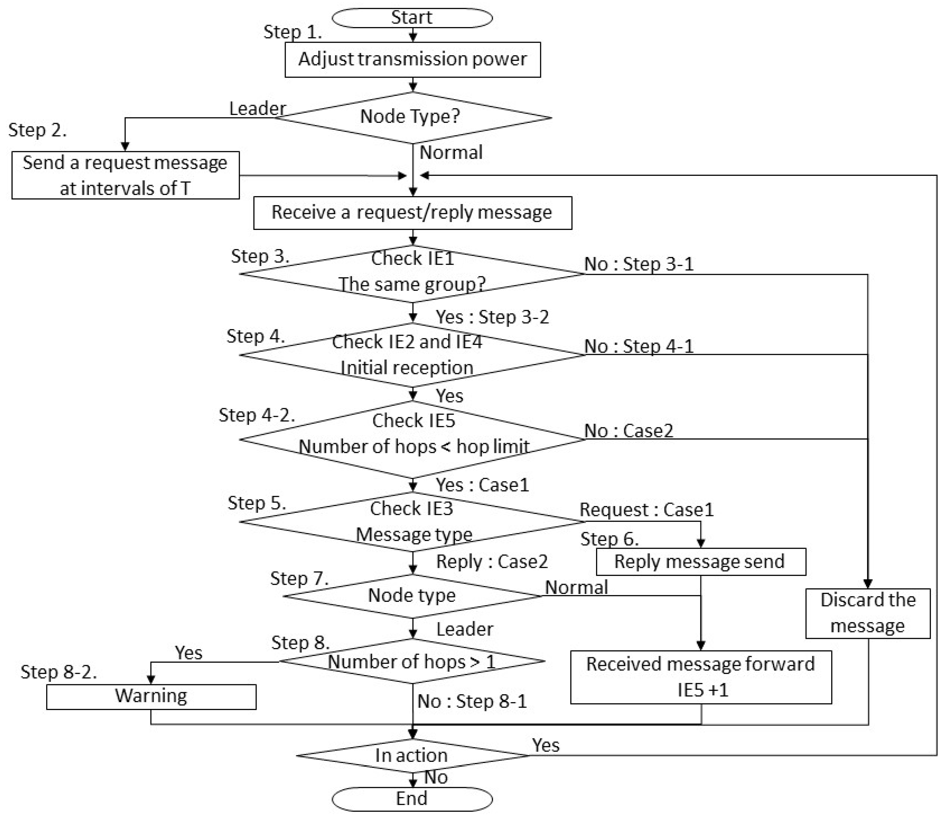
Each transmission node performs the following and a flowchart for this logic is shown in Figure 7.
- Step 1
- The area within which a message from the leader node can reach a node is adjusted by varying the transmission power of each node. Any node that is outside this area is regarded as a stray node.
- Step 2
- The leader node sends a request message at intervals of T.
- Step 3
- The receiving node checks IE1.
- 3–1
- If the node finds that the group ID in the message is different from its own group ID, it discards the message, go to Step 3.
- 3–2
- If the message was sent by a node belonging to the same group. Go to Step 4.
- Step 4
- The receiving node checks IE2 and IE4 to see if it has received the same message before.
- 4–1
- If it has, it discards the message, go to Step 3.
- 4–2
- If it has not it checks IE5.
- CASE 1
- Number of hops < hop limit, go to Step 5.
- CASE 2
- Number of hops = hop limit, it discards the message, go to Step 3.
- Step 5
- The receiving node checks IE3.list
- CASE 1
- If the message is a request message, go to Step 6.
- CASE 2
- If the message is a reply message, go to Step 7.
- Step 6
- The receiving node sends a reply message and forwards the request message with the number of hops in IE5 increased by one, go to Step 3.
- Step 7
- If the receiving node is the leader node, go to Step 8. If it is a normal node, forwards the received message with the number of hops in IE5 increased by one, go to Step 3.
- Step 8
- The leader node examines IE5 in the message returned by each node.
- 8–1
- If the number of hops is 1, it determines that the sending node is not a stray node, go to Step 3.
- 8–2
- If the number of hops is 2 or greater, it determines that the sending node is a stray node, and alerts the instructor, go to Step 3.
4.2.2. Collision Avoidance Method
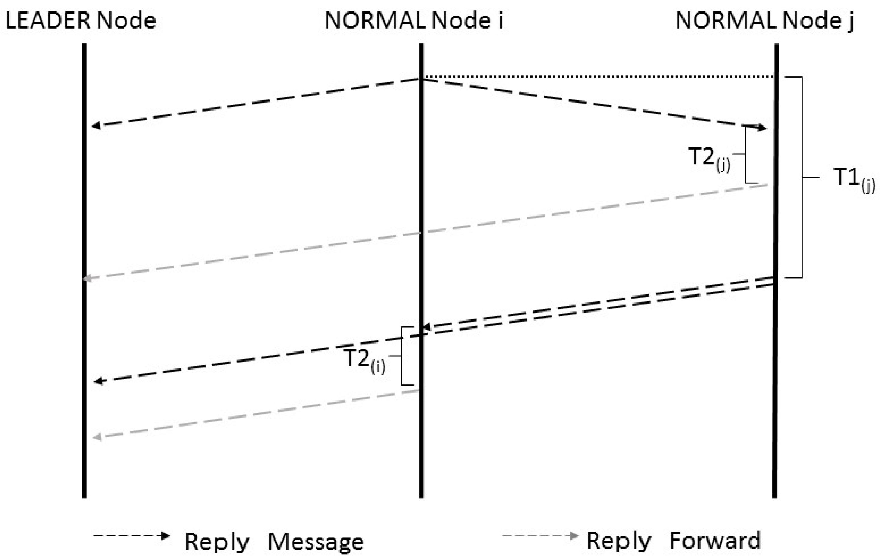
In this protocol, a normal node that has received a REQUEST message from the leader node sends a REPLY message and forwards the REQUEST message. If all normal nodes do this simultaneously, bursty traffic arises. To prevent this, the message transmission timing is varied according to the message type. Figure 8 shows a sequence diagram for this collision avoidance method. To avoid a collision, a node that has received a request message begins to count delay time T3(i). When T3(i) has elapsed, the node returns a reply message and forwards the request message after T2(i). A node that has received a reply message begins to count delay time T2(i). When T2(i) has elapsed, it forwards the message.
T3(i) = ID × δd × hop limit
5. Development of an Evaluation System
The group mobility model and the underwater environment model used for evaluation of the proposed protocols are described below. A method of controlling the transmission power to restrict communication and the packet format used in the proposed protocols are also presented.
5.1. Group Mobility Model
An evaluation system has been developed by custom-coding Scenargie Simulator [12]. In order to implement a mobility model that represents group members moving together, RandomWaypoint of the default mobility model in Scenargie Simulator has been extended into GroupBasedRandomWayPoint. Figure 9 shows its transition model. GroupBasedRandomWayPoint is a mobility model in which nodes move together within a certain area. It can be set in such a way that some nodes in the group move away from the group and go astray at a certain probability. In water, nodes can move in three dimensions. Figure 9a shows the state at the beginning of the simulation. In this mobility model, nodes can move to only a limited area, which is called a normal node moving area. Figure 9b shows how the next moving area is determined. The next moving area is set at random. Each node determines its next point inside the next moving area at random. However, some nodes may move to a point located in a wider area around the normal moving area. This area is called a stray node attention area. The normal moving area and the stray node attention area constitute the node movable area. Any node other than the leader node may become a departing node at a certain probability called a departure rate, RD. A departing node moves ignoring the node movable area. Figure 9c shows a state after nodes have moved to their respective next points. The departing node stays at this next point thereafter. In contrast, a node that has moved to a stray node attention area goes on moving.
5.2. Implementation of the Underwater Propagation Attenuation Model in the Low-Frequency Band
5.2.1. Propagation Attenuation Equation
An attenuation equation that can model underwater communication has been developed. It can be expressed as a sum of diffusion loss and absorption loss [13,14]. As a sound wave propagates through seawater, its acoustic energy is converted into other types of energy, resulting in the sound wave being absorbed in water. This is called absorption loss. It is necessary to define an absorption coefficient to calculate absorption loss. As an empirical equation for absorption coefficient, Ainslie and McColm equation created based on Francois and Garrison’s equation has been used. This equation is simpler than that of Francois and Garrison and yet is said to give values closer to empirical values. Absorption loss (AL) is expressed by:
where d is an inter-node distance, and a(f) is an absorption coefficient. Since absorption loss is expressed in dB, the relation between absorption loss and an absorption coefficient is expressed by:
where α is an absorption coefficient. Using Ainslie and McColm equation [15], it is expressed by:
where T is water temperature (°C), D is water depth (m), S is salt concentration (‰), and f is frequency (Hz). Further details of the equation are given in reference [15].
Next, diffusion loss is the surface pressure of a spherical space. Therefore, it can be calculated in the same way as the spatial loss of a terrestrial free space is calculated. Diffusion loss is expressed by:
where k is a diffusion factor (1 ≤ k ≤ 2), and a(f) is an absorption coefficient. In shallow water, a sound wave does not spread in a spherical shape but in a cylindrical shape. Therefore, k = 1. In deep water where there is no obstacle, a sound wave spreads in a spherical shape. In that case, k = 2. In Equation (4), l is an inter-node distance (km). As mentioned earlier, underwater propagation attenuation is a sum of diffusion loss and absorption loss. Thus, it is expressed by:
Underwater propagation attenuation varies depending on the frequency and inter-node distance.
5.2.2. Underwater Noises
For underwater communication, it is necessary to consider not only the attenuation equation but also noises. In this paper, the following three equations are considered. They respectively relate to thermal noise (Nth), ship noise (Ns) and wave noise (Nw) [16]
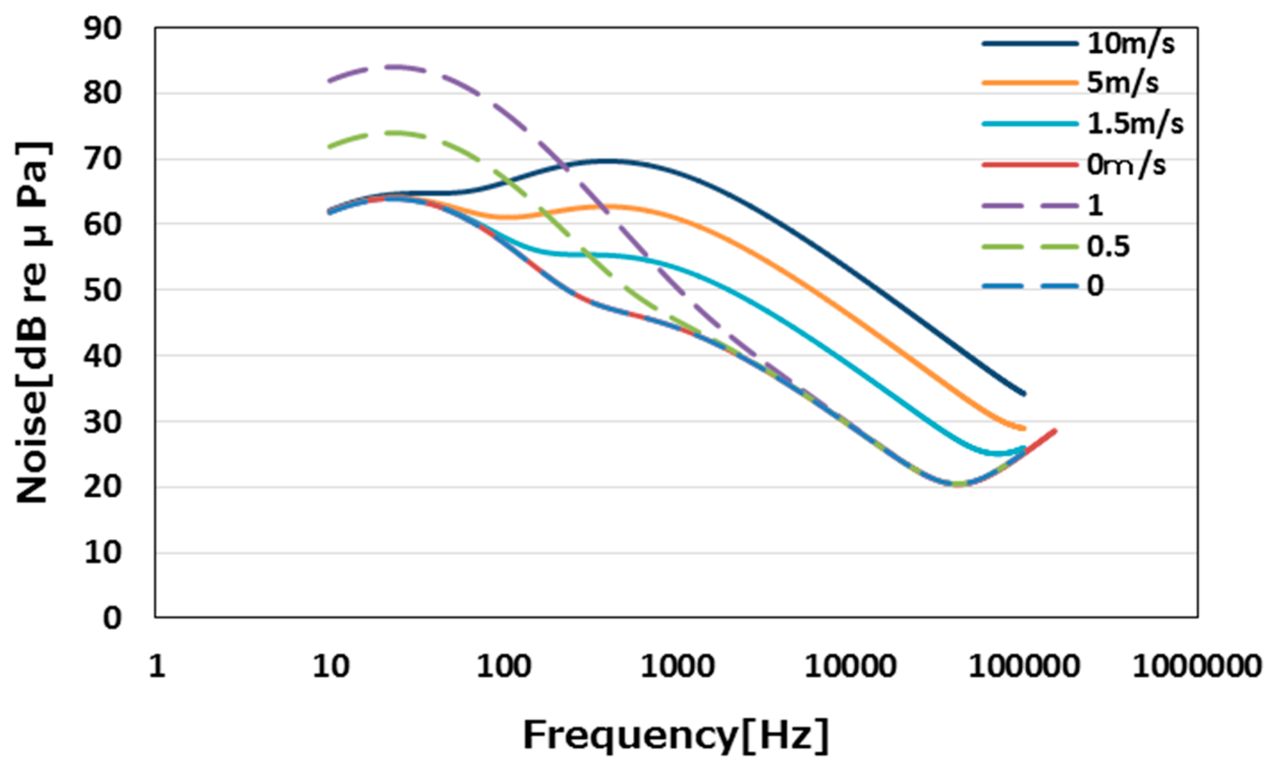
where s represents the influence of ship, and w is wind speed (m/s). The value of s ranges between 0 (no influence) and 1 (heavy influence). The influences of these noises at different frequencies are shown in Figure 10.
In Figure 10 the solid lines show wave noises while the dotted lines show ship noises. The ship noise is significant at frequencies between about 10 Hz and 2000 Hz. The influence of wave noise is prominent at frequencies between about 100 Hz and 100 kHz. Since the present research focuses on data transmission, it uses a frequency band of 150 kHz in order to ensure a transmission speed above a certain level. At this frequency band, the influences of the wave noise and ship noise are not significant.
5.2.3. Underwater Propagation Delay
Since ultrasonic waves are used, propagation delay in water is much longer than that of terrestrial radio wave communication. This long delay is not negligible. Ultrasonic waves propagate much more slowly in water. Its speed is expressed by Equation (9) [16].
where T is water temperature (°C), D is water depth (m), S is salt concentration (‰). This speed is about 1500 m/s, which is approximately one-200,000th of that of radio waves. In other words, the propagation delay of ultrasonic waves in water is 200,000 times longer than that of radio waves. It takes about 13.3 ms for ultrasonic waves to travel 20 m. We implemented an underwater propagation model based on the summertime values in the Pacific Ocean near Japan. The assumed underwater environment is shown in Table 2.
c = 1412 + 3.21T + 1.19S + 0.0167D
5.3. Determining Transmission Power
In water, the packet arrival rate is affected by the frequency used and noises present. A preliminary experiment using simulation has been conducted to determine the necessary transmission power. In this simulation, which modeled an underwater environment, a source node sent a packet to a node at a certain distance.
The transmission power is adjusted in such a way that no packets travel beyond 20 m, the communication radius, r, assumed in the present research. Figure 11 shows how the packet arrival rate decreases with an increase in the inter-node distance. The figure shows that a small portion of packets arrives at the 21-m point in the case where the transmission power is 0.72 mW but no packets travel beyond 20 m in the case where the transmission power is 0.7 mW. Thus, we have decided to use transmission power of 0.7 mW.
5.4. Packet Format
Information elements used in the proposed protocol are laid out as shown in Figure 12.
The data link and lower layers are omitted in the figure. The IP header contains the multicast address (IE1) and the IP address (IE2). The data part is 24 Bytes long. It consists of the message type (IE3), the sequence number (IE4), which is used to determine whether the message concerned has already been received, and the multi-hop number (IE5), which is used to count the number of hops. The protocol header information at the application layer is normally written in text. In a similar manner, the message type, sequence number, and the multi-hop number fields are declared as a character type. Data content can be changed as necessary. However, in the present research, the “other data” part in the format is not used.
6. Evaluation
The proposed protocols have been evaluated using the model described in Section 5. The evaluation conditions used and evaluation results are discussed below. The proposed protocols have been compared with the ones that rely on CSMA/CA only for collision avoidance. The latter is referred to as a “compared protocol” in this paper. While the proposed protocols stagger message transmission timing at the application layer, the compared protocols make no attempt to avoid a collision. With a compared protocol based on autonomous response-type stray node detection, all nodes send a REPLY message simultaneously at T-second intervals. With a compared protocol based on request-response-type stray node detection, all nodes simultaneously send a REPLY message and forward a REQUEST message for detection of stray nodes. Table 3 lists the proposed and compared stray node detection protocols evaluated and their respective abbreviations. These abbreviations are used hereafter.
6.1. Evaluation Conditions
Different collision avoidance methods have been evaluated using the conditions summarized in Table 4. The transmission speed and the frequency band were selected on the assumption that S2CM-HS [17] from EvoLogics is used as data transmission devices. The wind speed is set to 5 m/s. This is a generally tolerated wind speed for scuba diving. The number of nodes and the node moving speed selected are also those common in scuba diving. The departure rate in the mobility model was set such that a node goes astray at a probability of about 5% throughout the simulation. The slot time and the SIFS (short interframe space) of CSMA/CA are changed to those appropriate for underwater communication. The slot time calculated is 512 bit/62.5 kbps. The value of SIFS is the same as that of the slot time. The value of DIFS is double the value of SIFS. Divers move more slowly than pedestrians. Since they move only 5 to 10 m per second, the transmission interval, T, is set to 10 s. Increasing T extends the interval at which packets arise, thereby reducing the chances of collision. However, it increases the risk of stray nodes moving far away. If, on the other hand, T is shortened, the interval at which packets arise is also reduced, increasing the likelihood of message collisions.
6.2. Evaluation Results
6.2.1. Number of Packet Occurrences
We compared the proposed collision avoidance methods (AR-Proposal, RR-Proposal) of both the autonomous response-type and the request-response-type stray node detection protocols for a case where collision avoidance relies on CSMA/CA only. In order to examine how much packet transmission attempts are distributed during the stray node detection processing in each collision avoidance method, we measured the number of packets that arose at each 10-ms interval in the case where the number of nodes was 15. The result is shown in Figure 13. Figure 13a,b show the number of packets that arose in the autonomous response-type stray node detection. Figure 13a shows that packet transmission attempts concentrated within the first three seconds from the start of the stray node detection processing. In contrast, Figure 13b shows that a small number of packets arose over a period of 7 s. Figure 13c,d show the number of packets that arose in the request-response-type stray node detection. Figure 13 c indicates that more than 24 packets arose simultaneously immediately after the start of the stray node detection processing. This bursty packet traffic occurred because each node that had received a REQUEST message returned a REPLY message and forwarded the REQUEST message almost simultaneously. In Figure 13d, there were no concentrations of packet transmission attempts. In any of these cases, packet transmission attempts were more distributed when the proposed protocols were used. The bursty traffic that occurred when the compared protocols were used resulted in packet loss.
6.2.2. Packet Loss Rate
The packet loss rate (PLR) of each protocol is shown in Figure 14. PLR is expressed by:
where N is the number of nodes, iReceived packets is the number of packets received by node i, and iDetected packets is the number packets detected by node i.
Figure 14a shows the packet loss rates of AR-Proposal and AR-Basic. They are both about 0.05 when the number of nodes is as small as 5. However, when the number of nodes increased to 10 or 15, the PLR of AR-Basic increased more than that of AR-Proposal. The former was greater than the latter by more than 0.1 when the number of nodes was 15. Figure 14b compares the packet loss rates of RR-Proposal with that of RR-Basic. The difference between the PLR of the former and that of the latter was about 0.05 irrespective of the number of nodes. Both AR-Proposal and RR-Proposal provide better collision avoidance because they stagger message transmission timing. When AR-Basic or RR-Basic was used, i.e., when collision avoidance relied on CSMA/CA only, an increase in the number of nodes resulted in a dramatic increase in the number of messages. This made it difficult for the collision avoidance processing to catch up, resulting in a dramatic increase in the packet loss rate. Figure 14c compares the packet loss rates of AR-Proposal with that of RR-Proposal. As the number of nodes increased, the PLR of AR-Proposal increased less than that of RR-Proposal. This is because AR-Proposal does not use REQUEST messages. This means that fewer packets are transmitted, resulting in a higher communication efficiency.
6.2.3. Stray Node Detection Rate
The stray node detection rate (SNDR) is calculated as follows.
where NDetection is the sum of the number of REPLY messages that have experienced timeout and the number of REPLY messages that returned after 2 or more hops, NStray is the number of nodes that are outside the detection area at the time of communication, and NTotal Detection is the number of nodes (N) × the number of detections.
SNDR = (1 − MDR) × 100
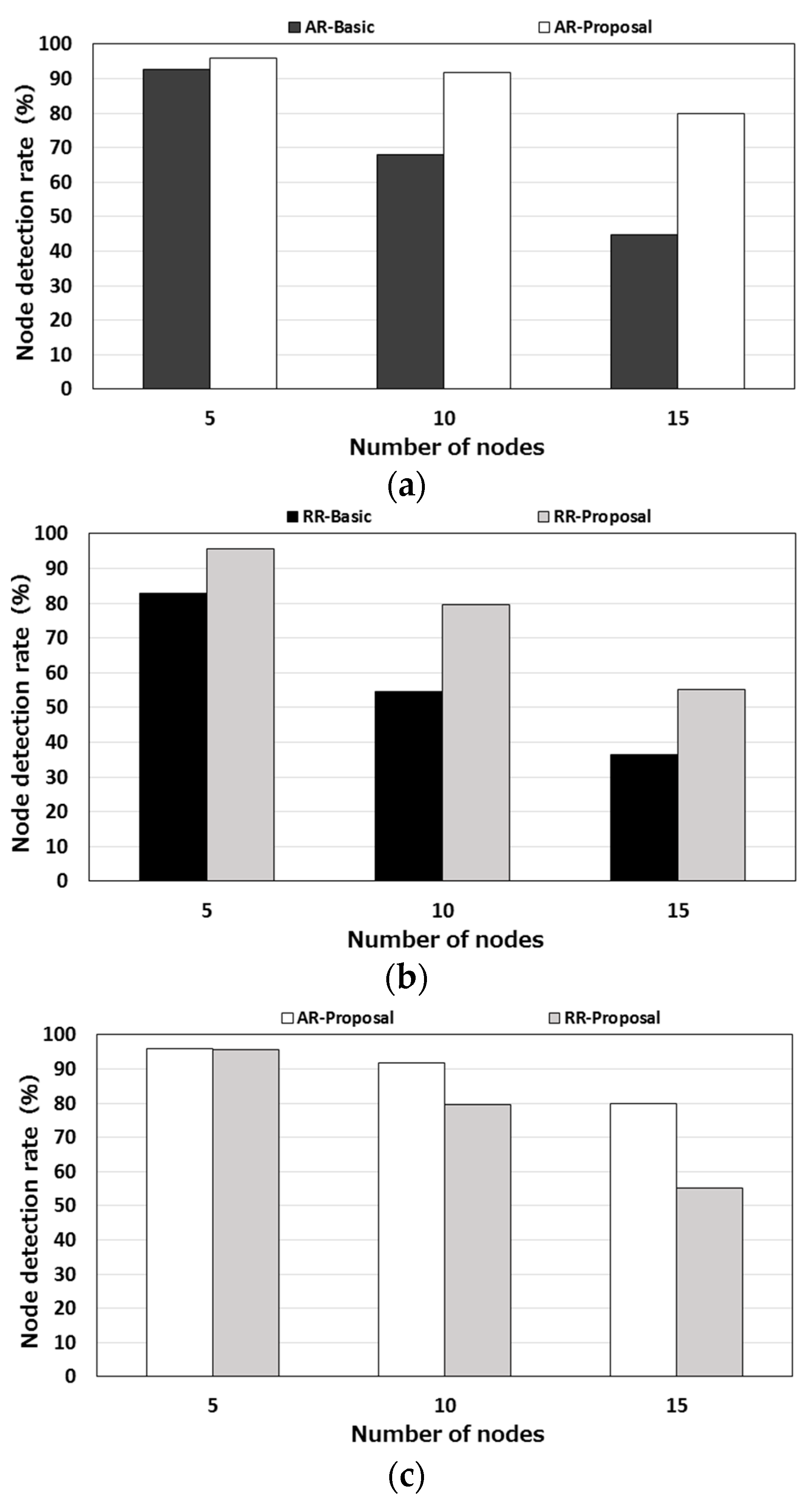
The node detection rate of each protocol is shown in Figure 15. Figure 15a shows the node detection rates of AR-Basic and AR-Proposal. As in the case of the packet loss rate, the detection rates of the two protocols did not differ much when the number of nodes was small. However, as the number of nodes increased, the node detection rate of AR-Basic dropped sharply. When the number of nodes was 15, the node detection rate of AR-Basic was 40% lower than that of AR-Proposal. Figure 15b shows the node detection rates of RR-Basic and RR-Proposal. Here again, the proposed protocol exhibited a higher node detection rate. The difference in the node detection rate between the two protocols was 10 to 20% irrespective of the number of nodes. Figure 15c compares the two proposed protocols. As in the case of the packet loss rate, the node detection rate of AR-Proposal was higher than that of RR-Proposal.
These results indicate that the proposed protocols provide more efficient communication than the compared protocols do and that the autonomous response-type stray node detection is better than the request-response-type stray node detection.
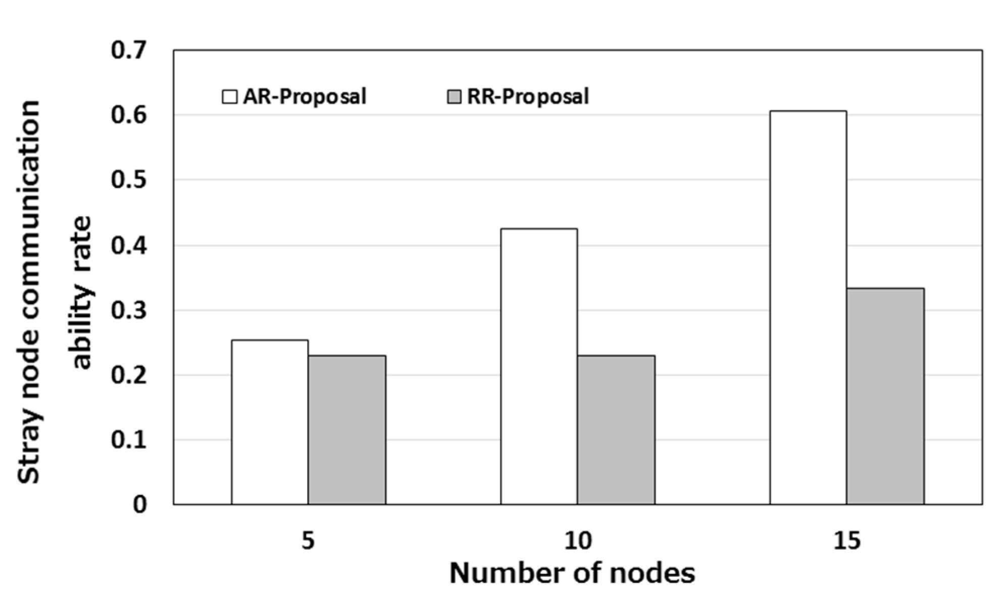
6.2.4. Rate of Ability for Stray Nodes to Communicate in Multiple Hops
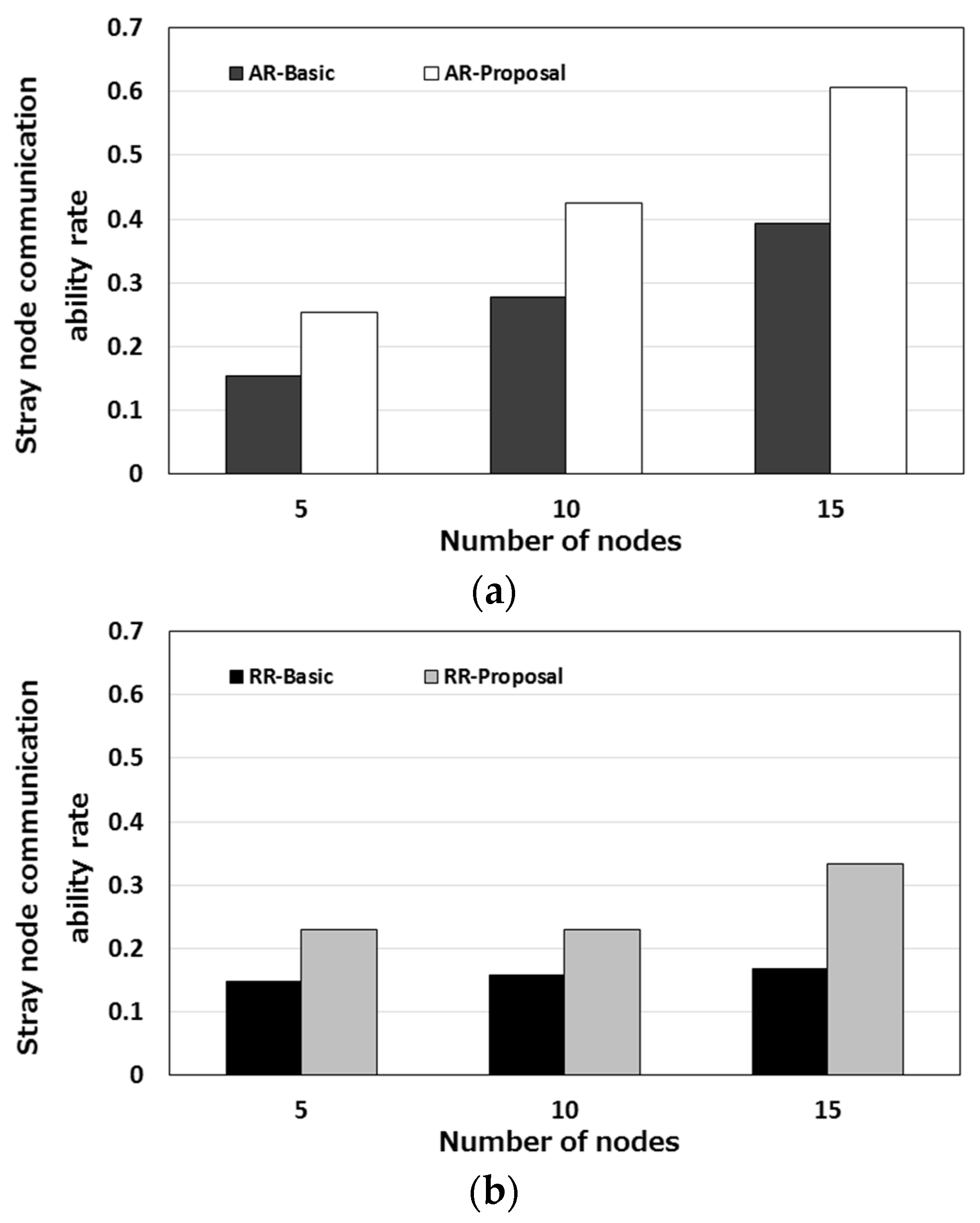
If a stray node can communicate with the leader node, it can return to the group. Therefore, it is desirable that communication with a stray node can be established in multiple hops. Figure 16 shows the rate of the ability for stray nodes to communicate in multiple hops. This rate is hereafter referred to as a “stray node communication ability rate.” This rate is calculated as follows.
where iNCAO is the number of communication attempts that node i has made outside the area, and iNTWO is the number of moments when node i went outside the area. Figure 16 indicates that stray nodes can communicate in multiple hops at a certain probability. It also shows that, as the number of nodes increased, the stray node communication ability also increased. An increase in the number of nodes results in an increase in the node density, which means that there are more relay nodes available. Figure 16a shows that, in the case of AR-Proposal, 60% of stray nodes were able to communicate. In Figure 16b, RR-Proposal took a higher communication ability rate than RR-Basic but the rate was less than half of the rate provided by AR-Proposal. Even when multiple hops are involved, the autonomous response-type stray node detection protocol provides a higher rate than other protocols.
These results indicate that using CSMA/CA only cannot avoid contention sufficiently and thus cannot detect stray nodes efficiently. The best protocol for detecting stray nodes is the autonomous response-type stray node detection protocol. However, as mentioned in Section 4, the request-response-type stray node detection protocol can reduce the number of communication attempts. In an environment in which terminals have limited power supply, it is important to reduce the number of communication attempts. In such an environment, the request-response-type stray node detection protocol can be a preferred protocol.
7. Conclusions and Future Issues
This paper has presented methods of detecting stray nodes in scuba diving by adjusting transmission power and using multiple hops. Specifically, two methods have been proposed: The autonomous response-type protocol and the request-response-type protocol. Since multiple terminals communicate via a single channel, the paper has also proposed a method of reducing channel contention by using the application layer to stagger transmission timing. To evaluate the proposed methods, an undersea environment has been modeled in a simulator, and propagation attenuation, noise and propagation delay have been implemented in the simulator. The relationship between the transmission output and the packet arrival rate has been investigated. Using the findings from this investigation as evaluation conditions, the proposed collision avoidance methods have been compared with CSMA/CA in terms of the packet loss rate and the stray node detection rate. It has been shown that the proposed collision avoidance using the application layer is more effective than using CSMA/CA only. It has also been shown that transmission of messages in multiple hops is effective.
Looking forward, we will try to prove that the proposed stray node detection protocols are useful in a more realistic environment that takes the battery levels of terminals into consideration and will evaluate the protocols using more varied parameter values to represent a wide variety of undersea environment. In the present research, the application layer is used to stagger message transmission attempts in order to avoid contention. We will investigate causes for packet loss and relations between them in detail to achieve efficient communication. For the same purpose, we will devise a network routing protocol that reduces message flooding. We will build a mobile ad-hoc network and study the effectiveness of routing-based contention avoidance.
Author Contributions
Shinya Kaido designed the proposed method, developed the software prototype of the evaluation system, collected the evaluation data and wrote the initial draft of the paper. Kazumasa Takami provided the direction for his research activities and refined the proposed method, the analysis of the evaluation results and the writing of the paper.
Conflicts of Interest
The authors declare no conflict of interest.
References
- Okinawa Prefecture. Churaumi Construction Promotion Project in 2009. Diving Industry Survey on Actual Condition in Okinawa; Okinawa Tourism Commerce & Industry, Tourism Promotion Department: Okinawa, Japan, 2010; pp. 2–37. [Google Scholar]
- Stefanov, A. Distortion Analysis of Underwater Acoustic Sensor Networks. In Proceedings of the New Technologies, Mobility and Security, Paris, France, 27–29 July 2015. [Google Scholar]
- Entezami, F.; Politis, C. 3DPBARP: A Three Dimensions Position Based Adaptive Real-Time Routing Protocol for Wireless Sensor Networks. In Proceedings of the New Technologies, Mobility and Security, Paris, France, 27–29 July 2015. [Google Scholar]
- Kong, J.; Cui, J.; Wu, D.; Gerla, M. Building Underwater Ad-hoc Networks for Large Scale Real-Time Aquatic Applications. In Proceedings of the IEEE Military Communications Conference 2005, Atlantic City, NJ, USA, 17–20 October 2005. [Google Scholar]
- Coutinho, R.W.L.; Boukerche, A.; Vieira, L.F.V.; Loureiro, A.F.L. Design Guidelines for Opportunistic Routing in Underwater Networks. IEEE Commun. Mag. 2016, 54, 40–48. [Google Scholar] [CrossRef]
- Heidemann, J.; Stojanovic, M.; Zorzi, M. Underwater sensor networks: applications, advances and challenges. Philos. Trans. R. Soc. Math. Phys. Eng. Sci. 2012, 370, 158–175. [Google Scholar] [CrossRef] [PubMed]
- Cui, J.; Kong, J.; Gerla, M.; Zhou, S. Challenges: Building Scalable and Distributed Underwater Wireless Sensor Networks for Aquatic Applications. IEEE Netw. 2006, 20, 12–18. [Google Scholar] [CrossRef]
- Logosease, Yamagata Casio Co., Ltd. Available online: http://logosease.yamagata-casio.co.jp/ (accessed on 17 October 2017).
- IEEE 802.11 Wireless Local Area Networks, The Working Group for WLAN Standards. Available online: http://www.ieee802.org/11/ (accessed on 24 December 2017).
- Peleato, B.; Stojanovic, M. Distance Aware Collision Avoidance Protocol for Ad-Hoc Underwater Acoustic Sensor Networks. IEEE Commun. Lett. 2007, 11. [Google Scholar] [CrossRef]
- Karn, P. MACA—A New Channel Access Method for Packet Radio. In Proceedings of the 9th Computer Networking Conference, London, ON, Canada, 22 September 1990. [Google Scholar]
- Space-Time Engineering, Scenargie. Available online: https://www.spacetime-eng.com/en/products (accessed on 27 September 2017).
- Japan Machinery Industry Association Corporation and Institute of Marine Industry Corporation. Research Report about Evolution of Marine Industry and Creation of New Business Due to Sophistication of Underwater Acoustic Communication in 2004. Available online: http://www.jmf.or.jp/japanese/houkokusho/kensaku/pdf/2005/16kodoka_15.pdf (accessed on 10 October 2017).
- Jesus Llor, J.; Malumbres, M.P. Underwater Wireless Sensor Networks: How Do Acoustic Propagation Models Impact the Performance of Higher-Level Protocols? Sensors 2012, 12, 1312–1335. [Google Scholar] [CrossRef] [PubMed]
- García, M.; Sendra, S.; Atenas, M.; Lloret, J. Underwater Wireless Ad-hoc Networks: A Survey. In Mobile Ad-Hoc Networks: Current Status and Future Trends; Jonathan, L., Jaime, M., Jesus, H., Eds.; CRC Press Taylor and Francis: New York, NY, USA, 2011; pp. 350–409. [Google Scholar]
- Tan, D.D.; Kim, D. Cooperative transmission scheme for multi-hop underwater acoustic sensor networks. Int. J. Commun. Netw. Distrib. Syst. 2015, 14, 1–18. [Google Scholar] [CrossRef]
- EvoLogics, S2CM HS. Available online: https://www.evologics.de/en/products/acoustics/s2cm_hs.html (accessed on 10 October 2017).
Figure 1.
Position of the proposed transmission medium multi-access contention avoidance technology.
Figure 1.
Position of the proposed transmission medium multi-access contention avoidance technology.

Figure 2.
Assumed usage.
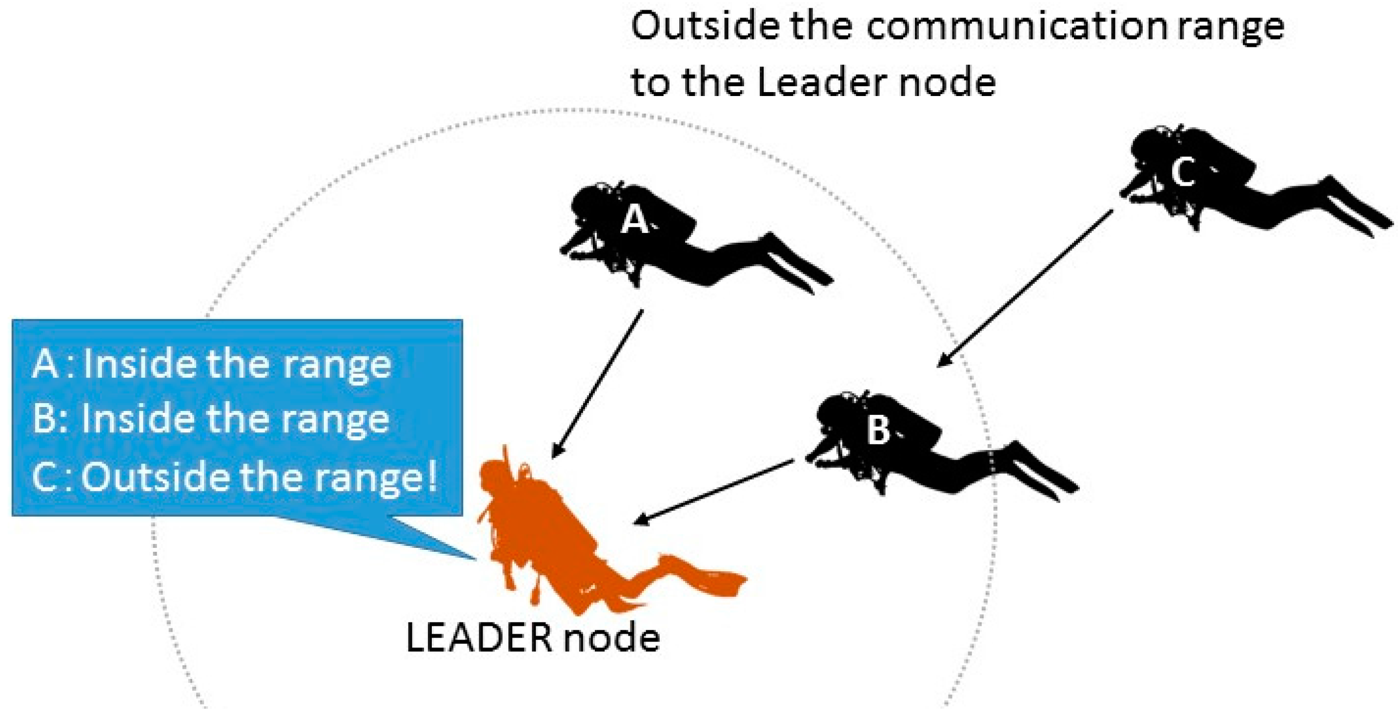
Figure 3.
Overview of the stray node detection protocol.
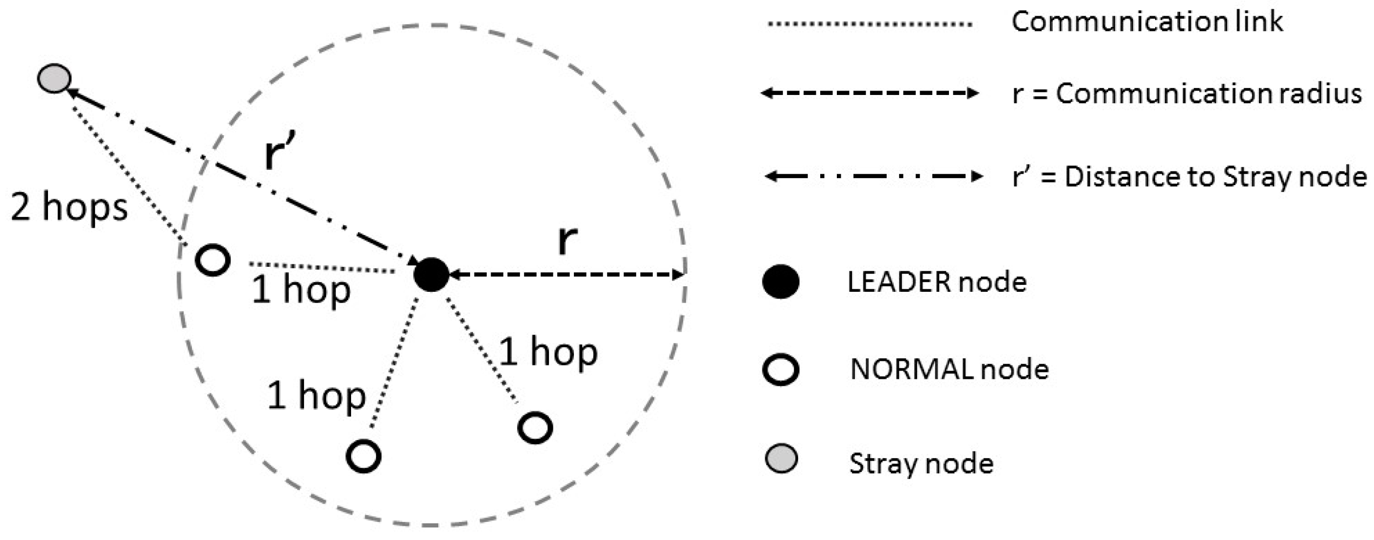
Figure 4.
Assumed protocol stack.
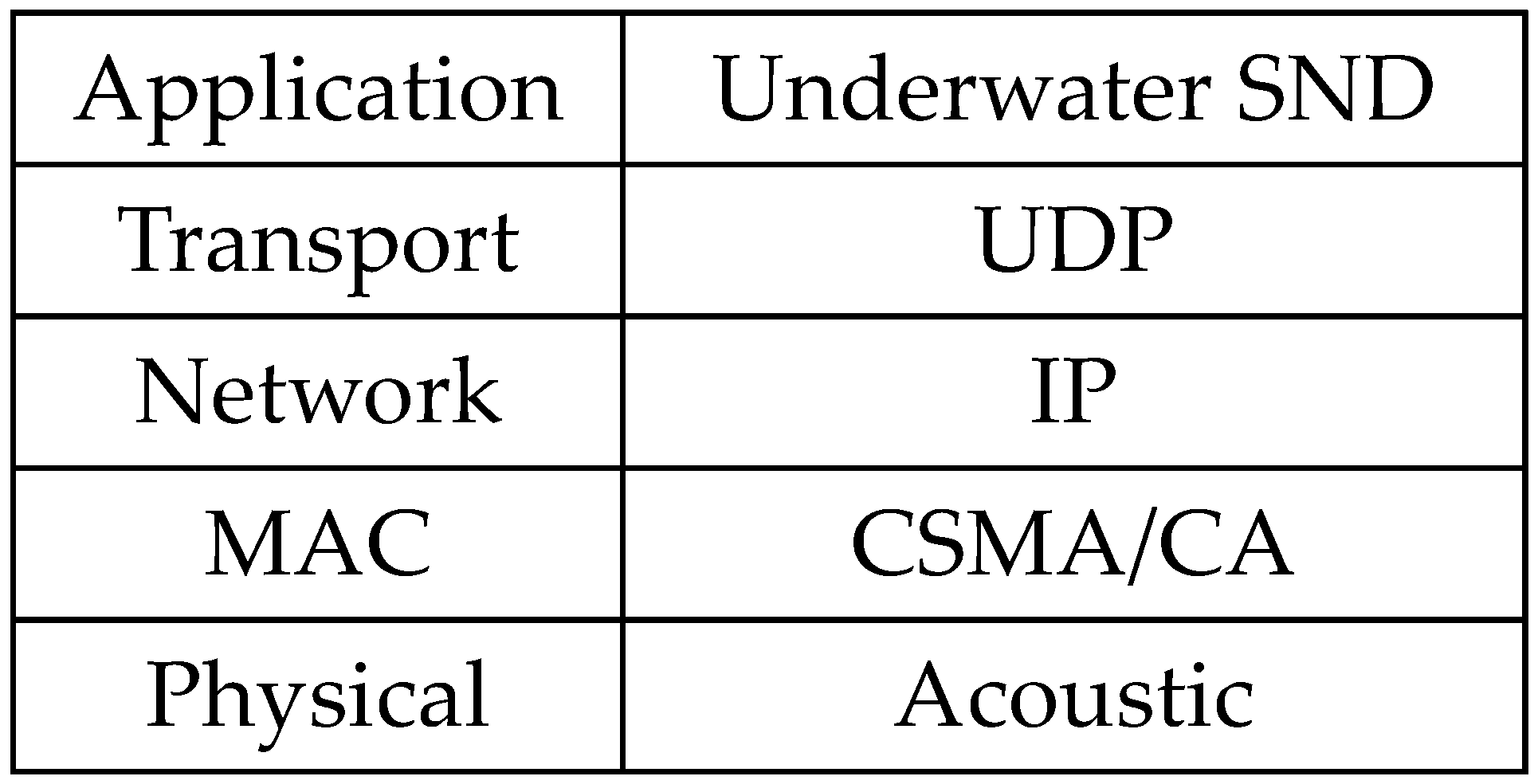
Figure 5.
Flowchart for the autonomous response-type stray node detection protocol.
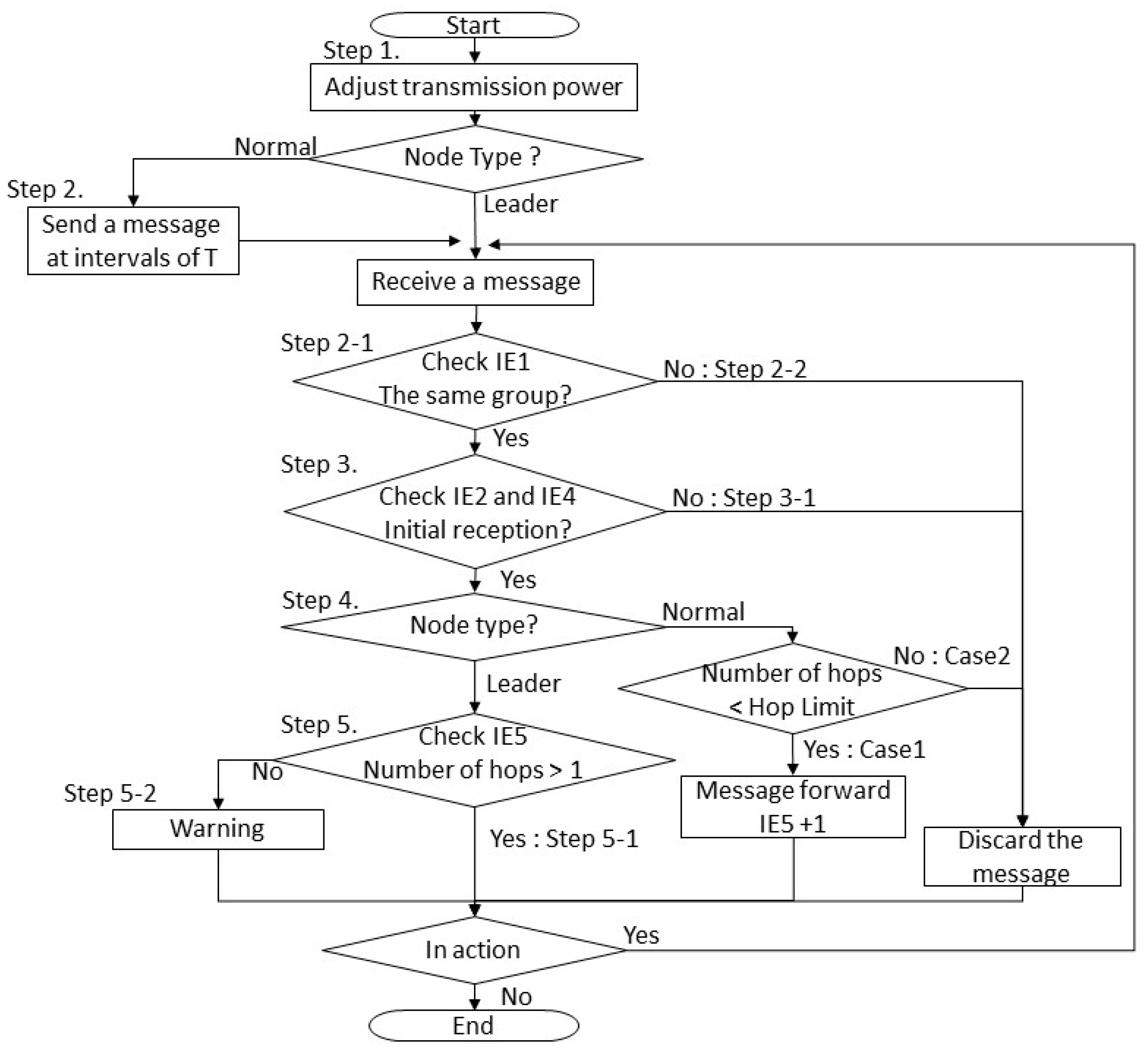
Figure 6.
Message transmission sequence of the collision avoidance method using the autonomous response-type protocol.
Figure 6.
Message transmission sequence of the collision avoidance method using the autonomous response-type protocol.

Figure 7.
Flowchart for the request response-type stray node detection protocol.

Figure 8.
Message transmission sequence of the collision avoidance method using the request-response-type stray node detection protocol.
Figure 8.
Message transmission sequence of the collision avoidance method using the request-response-type stray node detection protocol.
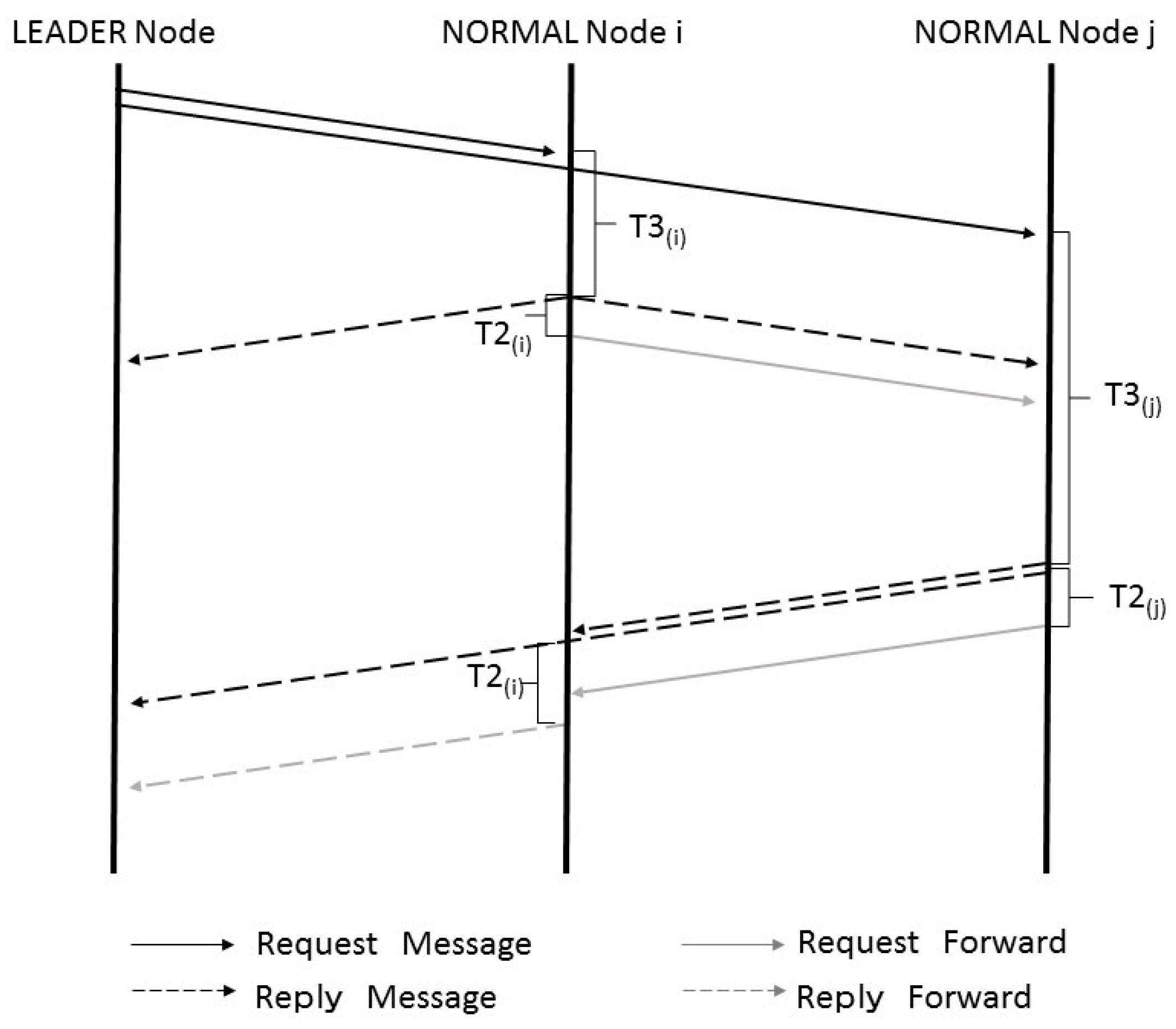
Figure 9.
Example transition model of Group Based Random Way Point: (a) At the beginning of the simulation; (b) determination of the next points; (c) movement after the previous movement.
Figure 9.
Example transition model of Group Based Random Way Point: (a) At the beginning of the simulation; (b) determination of the next points; (c) movement after the previous movement.
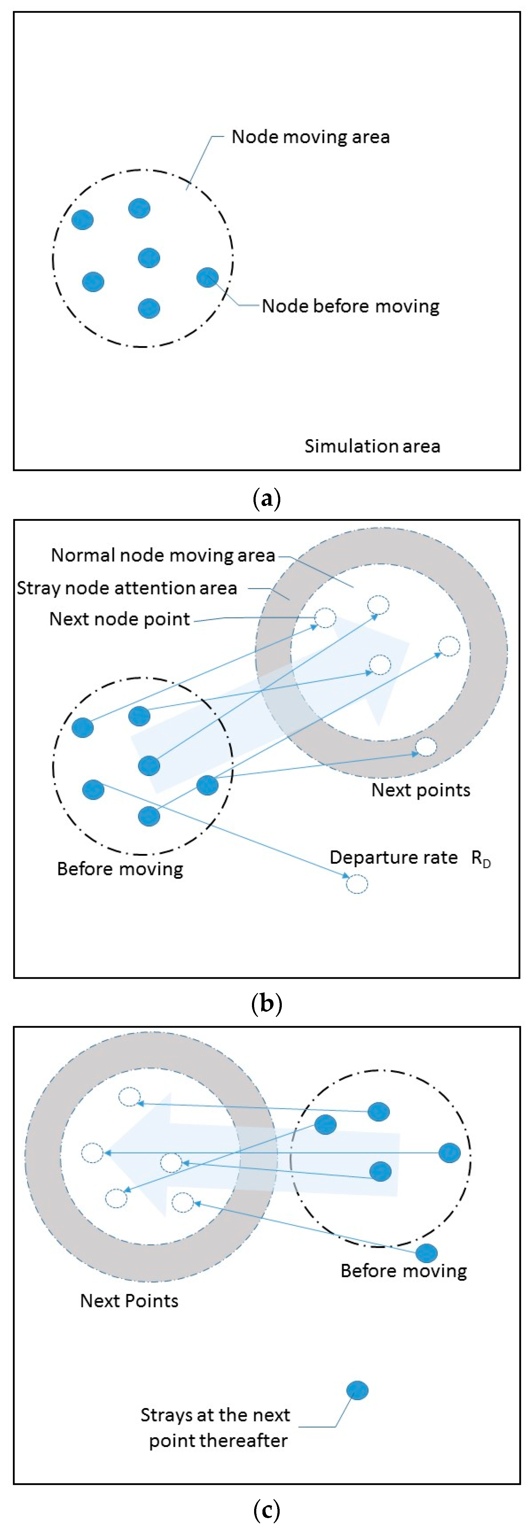
Figure 10.
Influences of various noises at different frequencies.

Figure 11.
How the packet arrival rate varies with transmission power.

Figure 12.
Packet format used by the stray node detection application.
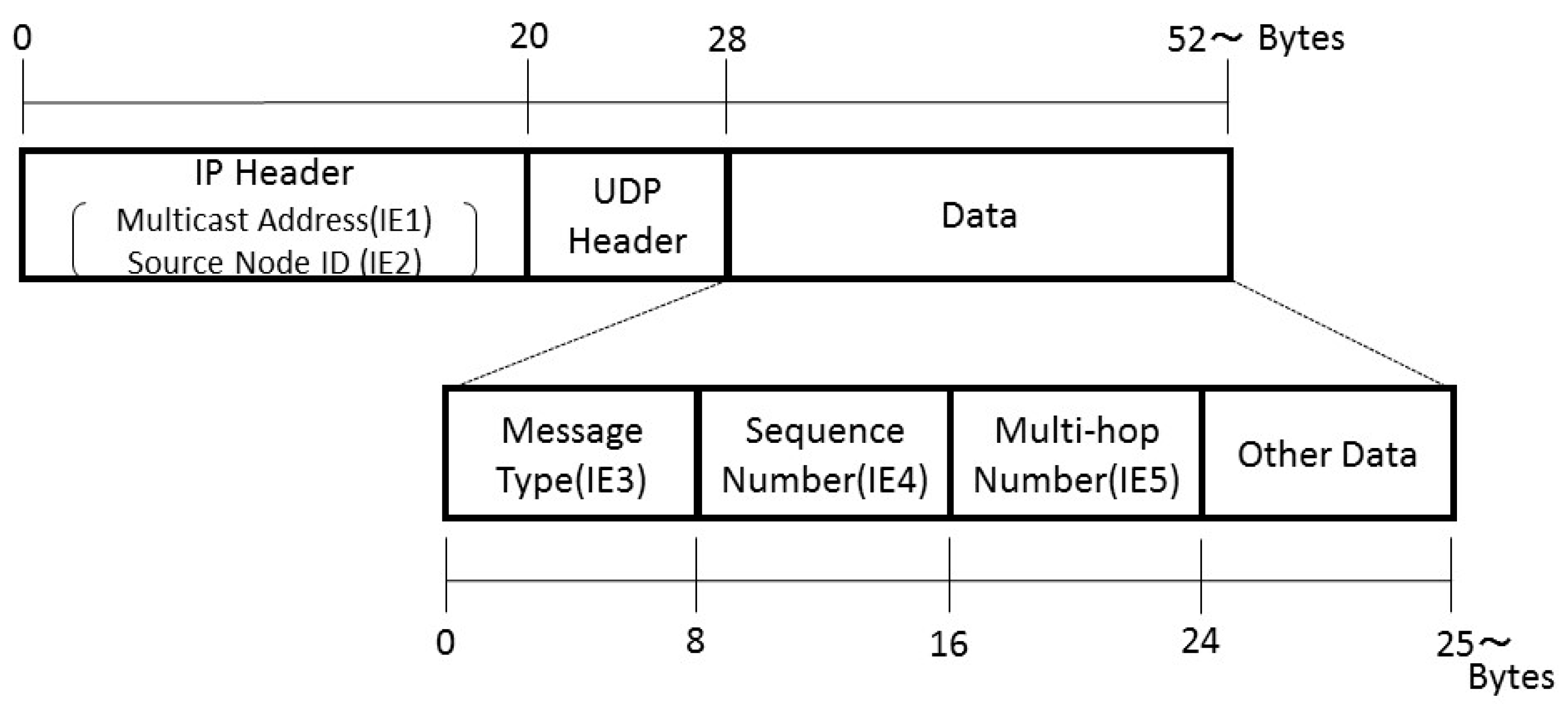
Figure 13.
Number of packets that arose in each 10-ms interval during stray node detection processing in the case where the number of nodes was 15. (a) AR-Basic; (b) AR-Proposal; (c) RR-Basic; and (d) RR-Proposal.
Figure 13.
Number of packets that arose in each 10-ms interval during stray node detection processing in the case where the number of nodes was 15. (a) AR-Basic; (b) AR-Proposal; (c) RR-Basic; and (d) RR-Proposal.
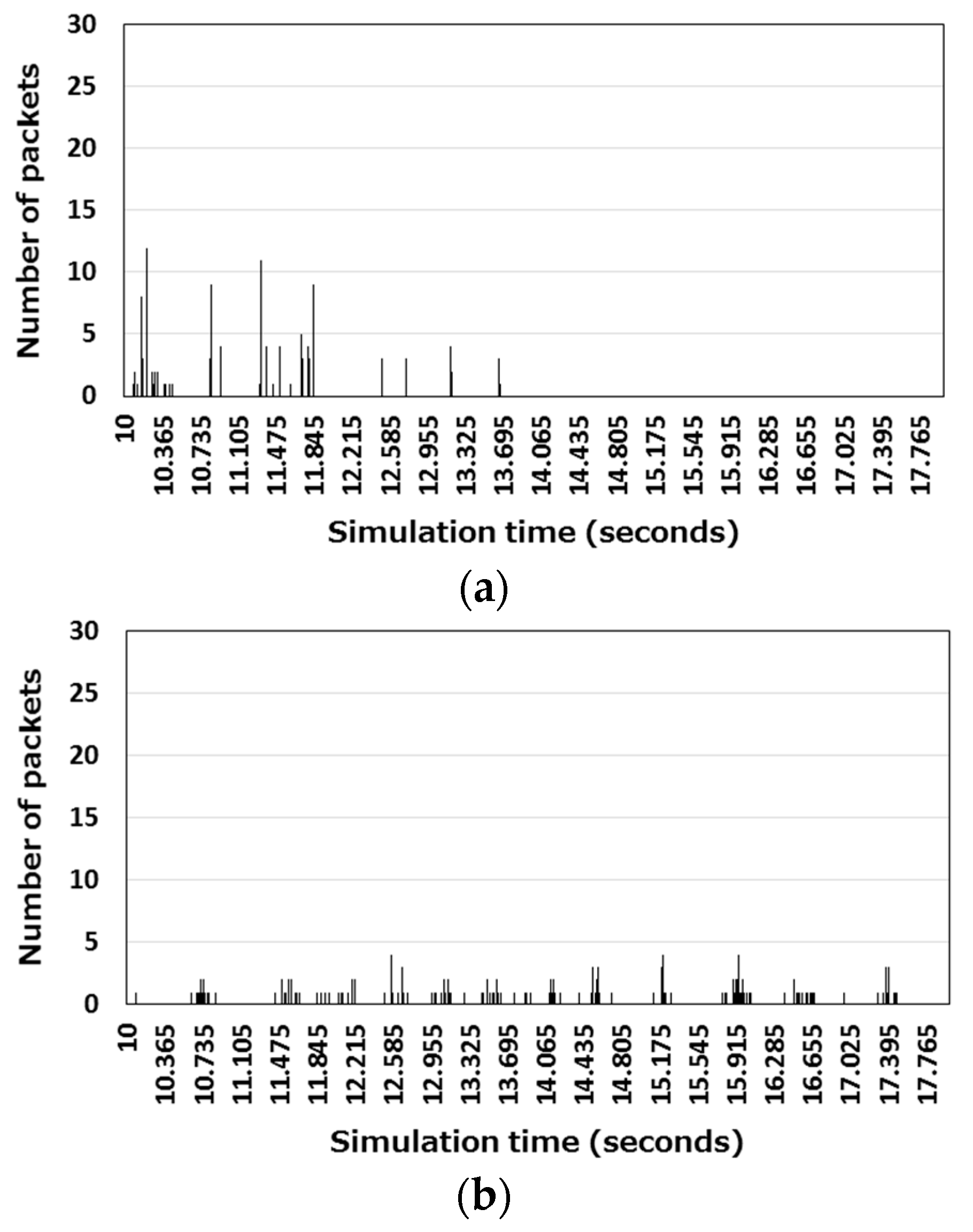
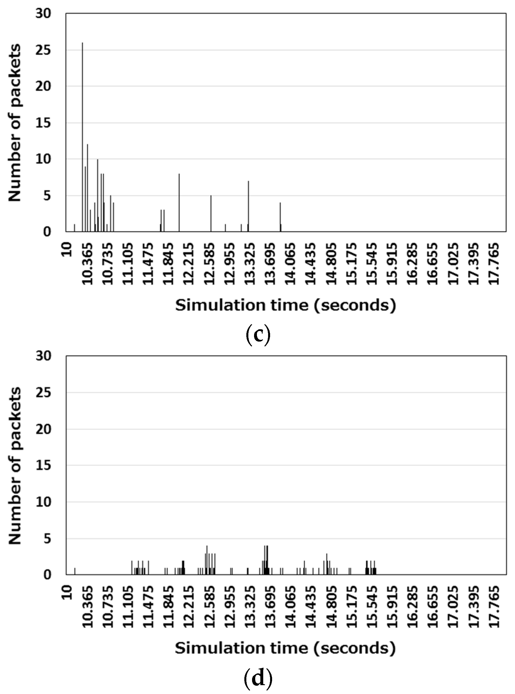
Figure 14.
Packet loss rate: (a) Packet loss rates of the autonomous response-type stray node detection protocol; (b) packet loss rates of the request-response-type stray node detection protocol; (c) Packet loss rates of the two proposed protocols.
Figure 14.
Packet loss rate: (a) Packet loss rates of the autonomous response-type stray node detection protocol; (b) packet loss rates of the request-response-type stray node detection protocol; (c) Packet loss rates of the two proposed protocols.
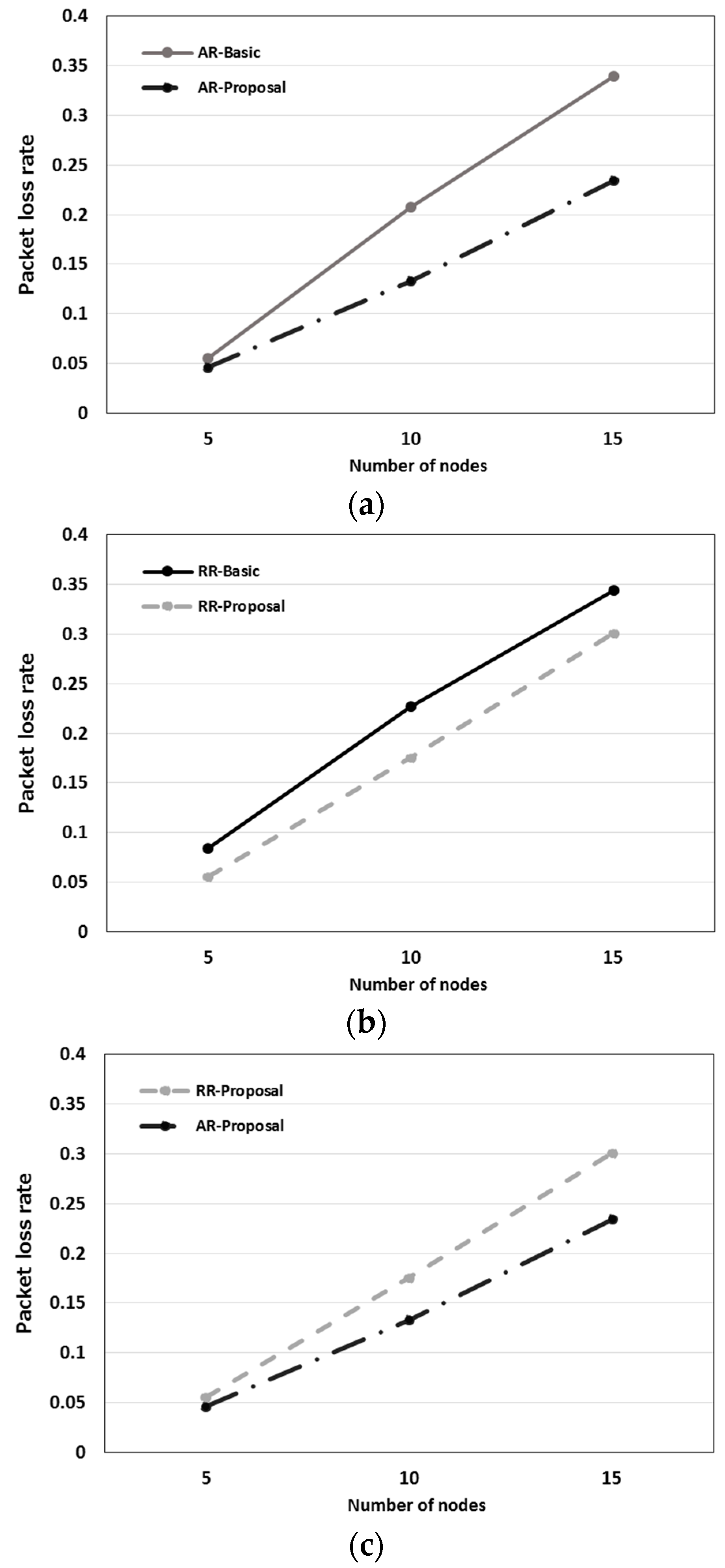
Figure 15.
Stray node detection rate. (a) Node detection rates of the autonomous response-type stray node detection protocol; (b) node detection rates of the request-response-type stray node detection protocol; (c) node detection rates of the proposed protocols.
Figure 15.
Stray node detection rate. (a) Node detection rates of the autonomous response-type stray node detection protocol; (b) node detection rates of the request-response-type stray node detection protocol; (c) node detection rates of the proposed protocols.

Figure 16.
Stray node communication ability rate. (a) Stray node communication ability rates of the autonomous response-type stray node detection protocols; (b) stray node communication ability rates of the request-response-type stray node detection protocol; (c) stray node communication ability rates of the proposed protocols.


Table 1.
Characteristics of the autonomous response-type and the request-response-type protocols.
| Item | Autonomous Response-Type Stray Node Detection | Request-Response-Type Stray Node Detection |
|---|---|---|
| User operation | Not required | Required |
| Frequency of communication attempts | High | Low |
| Communication initiating node | normal node | leader node |
Table 2.
Undersea conditions.
| Item | Set Value |
|---|---|
| Underwater depth (D) | 10 m |
| Temperature (T) | 25 °C |
| Salt concentration (S) | 34.17 ‰ |
| pH | 8.1 |
| Underwear sound velocity | 1532.912 m/s |
| Field size | 200 × 200 × 10 m3 |
| Diffusion factor | 1 |
| Sipping activity | 0 |
| Wind speed | 5 m/s |
Table 3.
Stray node detection protocols evaluated and their abbreviations.
| Stray Node Detection Type | Evaluated Protocol | Processing Logic | Collision Avoidance Method | Medium Access Control | Abbreviation |
|---|---|---|---|---|---|
| Autonomous response type | Proposed protocol | Refer to Section 4.1.1 | Used (refer to Section 4.1.2) | CSMA/CA | AR-Proposal |
| Compared protocol | Not used | AR-Basic | |||
| Request response type | Proposed protocol | Refer to Section 4.2.1 | Used (refer to Section 4.2.2) | RR-Proposal | |
| Compared protocol | Not used | RR-Basic |
Table 4.
Simulation conditions.
| Item | Value |
|---|---|
| Simulation time | 2000 s |
| Number of nodes | 5, 10, 15 |
| Node velocity | 1~5 km/h |
| Stray node detection distance (r) | 20 m |
| Transmission power | 0.7 mW |
| Mobility model | Group Based Random Waypoint |
| Leave probability (RD) | 0.001 |
| Frequency | 150 kHz |
| Propagation delay time (δd) | 100 ms |
| Random time | 0~100 ms |
| Self Time | 500 ms |
| Transmission rate | 62.5 kbps |
| Payload length | 24 Bytes |
| Transmission interval (T) | 10 s |
| Timeout | 9 s |
| Hop limit | 3 |
| Slot time | 8.19 ms |
| SIFS | 9.1 ms |
© 2017 by the authors. Licensee MDPI, Basel, Switzerland. This article is an open access article distributed under the terms and conditions of the Creative Commons Attribution (CC BY) license (http://creativecommons.org/licenses/by/4.0/).
Share and Cite
MDPI and ACS Style
Kaido, S.; Takami, K. Message Collision Avoidance Protocols for Detecting Stray Nodes in a Scuba Diving Group Using Ultrasonic Multi-Hop Message Communication. Appl. Sci. 2018, 8, 24. https://doi.org/10.3390/app8010024
AMA Style
Kaido S, Takami K. Message Collision Avoidance Protocols for Detecting Stray Nodes in a Scuba Diving Group Using Ultrasonic Multi-Hop Message Communication. Applied Sciences. 2018; 8(1):24. https://doi.org/10.3390/app8010024
Chicago/Turabian StyleKaido, Shinya, and Kazumasa Takami. 2018. "Message Collision Avoidance Protocols for Detecting Stray Nodes in a Scuba Diving Group Using Ultrasonic Multi-Hop Message Communication" Applied Sciences 8, no. 1: 24. https://doi.org/10.3390/app8010024
Note that from the first issue of 2016, this journal uses article numbers instead of page numbers. See further details here.