A Low-Power WLAN Communication Scheme for IoT WLAN Devices Using Wake-Up Receivers


1
School of Electrical & Electronic Engineering, Yonsei University, 50 Yonsei-ro, Seodaemun-gu, Seoul 03722, Korea
2
Department of Railroad Electrical & Electronic Engineering, Korea National University of Transportation, 157 Cheoldobangmulgwan-ro, Uiwang-si, Gyeonggi-do 16106, Korea
*
Author to whom correspondence should be addressed.
Appl. Sci. 2018, 8(1), 72; https://doi.org/10.3390/app8010072
Submission received: 15 November 2017
/
Revised: 21 December 2017
/
Accepted: 5 January 2018
/
Published: 7 January 2018
Abstract
:Featured Application
IoT devices with wireless LAN (WLAN) communication.
Abstract
In this paper, we propose a delay- and power-efficient, multi-user, low-power wireless local area network (WLAN) communication scheme for Internet of Things (IoT) WLAN devices. Extremely low-power operation is one of the key requirements of emerging IoT devices. However, the current duty-cycle-based power saving approach may incur large access delay times owing to the trade-offs between the power consumption and the access delay. In order to reduce this delay and enhance the power-saving performance, wake-up receiver-based schemes have been proposed. However, because wake-up receiver-based schemes do not consider multiuser operation in dense communication environments, large delays are inevitable in the case of multiuser operation. In order to provide extremely low-power operation and under 1-mW standby power with reduced delay, we employed the optimized multiuser transmission scheduling of IEEE 802.11ax in the proposed scheme and proper enhanced distributed channel access (EDCA) parameter settings. This is with the aim to reduce the delay caused by long wake-up times, and to avoid collisions caused by simultaneous transmission in uplink multiuser scenario. By using the proposed scheme, simultaneous IoT communication with multiple mobile IoT devices is possible while providing low-power operation. Simulation results verified the outstanding delay performance of the proposed scheme.
1. Introduction
The Internet of Things (IoT) has become more widely used in various applications, such as home networks, wearable devices, cattle farms, and warehouses. In most IoT applications, IoT devices are battery powered, and low-power operation is therefore one of the key requirements of IoT devices. Moreover, there are various applications for IoT devices, and there exist a variety of communication scenarios as well as power and delay requirements.
The research on low-power communication has focused on sensor networks. Most of the previous works have focused on distributed sensor networks, which include tree construction, duty-cycled operation, and wireless energy harvesting operations [1,2]. In duty-cycled operation, sensors turn on and off their transceivers at predetermined times in order to reduce unnecessary power consumption when not transmitting or receiving data. Duty-cycled operation includes a synchronized approach [3] and an asynchronous duty-cycled operation [4,5]. In [3], a sending node scheduled transmission to a receiving node during a Data period, and performed a transmission procedure during a Sleep period. In [4], a receiving node first transmitted a Beacon frame after it woke up, and a sending node transmitted data as a response to the Beacon frame. The power saving protocol in [5] is an improvement on [4] which considers multiple traffic flows. In [5], each sensor woke up at randomized times using a pseudo-random number generator to avoid collision. In this method, if a sensor node wants to know the wake-up interval of the receiving node, it requests and receives the parameters of the pseudo-random number generator, and uses them to predict the awake time of the receiving node. Duty-cycled power saving protocols handle various systems and traffic models in sensor networks with a small overhead. However, since the previous duty-cycled power saving protocols were based on relay operation from a source node to a destination node, tree construction should be part of the framework. Therefore, the previous duty-cycled power saving methods in wireless sensor networks were not efficient for IoT devices with mobility. Moreover, the duty-cycled operation requiring wireless devices to turn on and off at scheduled times causes trade-offs between latency and power consumption.
The IoT scenarios are different from sensor network scenarios in several aspects, although they may appear similar. First, in sensor networks, once the devices are implemented, the sensors are static and rarely move, while IoT devices may move around. Second, while low traffic arrival is assumed in sensor networks, in IoT applications, there are various traffic patterns with different delay requirements. In order to deal with such dynamic IoT communication environments and various IoT traffic types, centralized network structures, such as in wireless local area networks (WLANs), are more efficient than distributed sensor network structures.
Several power saving methods and control systems for IoT operation have been proposed based on WLAN. In [6], an AP power saving method based on the distance value of a station (STA) has been proposed. Whereas the idea of managing AP operation by average distance calculated by received signal strength indicator (RSSI) is simple and effective in the dense AP scenario, such an AP power saving method cannot reduce the power consumption of STAs. In [7], a management system to control home appliances was proposed which takes into account the coexistence of heterogeneous networks. However, client nodes (home appliances) were only turned off and on based on their utilization. The proposed system in [7] does not provide a power efficient communication method. In [8], the authors have proposed an effective handoff procedure and AP selection mechanisms based on a certain medium access control (MAC) protocol called distributed queueing with collision avoidance (DQCA). By using the proposed effective AP selection mechanisms, STAs with mobility are able to reduce the number of handoffs, leading to reduced power consumption.
In the IEEE 802.11 group, the IEEE 802.11ah standard has been developed recently for low-power and long-range operation [9,10]. The main features of IEEE 802.11ah is narrow band transmission and scheduled wake-up operation called target wake time (TWT). IEEE 802.11ah effectively manages power consumption and a large number of STAs, but there is a trade-off between latency and power consumption. Since power management operation is based on a scheduled wake-up procedure, trade-off occurs because the latency for STAs to receive data depends on the length of the wake-up cycle.
In order to achieve the low-power operation and short communication delay required for battery powered WLAN devices, wake-up receivers were proposed in [11,12,13,14]. The wake-up receiver is a simple structured receiver which detects on-off keying (OOK) signals, enabling low-power operation and short transmission delay, simultaneously.
The previous power-saving operations using wake-up receivers are primarily for conventional sensor networks. The main scenario involves a large number of devices with a low traffic ratio and a simple structure. In [15], the authors proposed the two-channel-based wake-up protocol. In the two-channel wake-up protocol, one channel is used to transmit data, and the other channel is used only to wake up neighboring STAs. In this protocol, the sender node may wake up all neighboring nodes through a wake-up channel when the sender has more data to transmit than the threshold. However, by using two channels without any indication, power may be wasted because all nodes which sense a signal in the wake-up channel should wake up and sleep including the nodes without data to receive, and other devices that operate at similar frequencies with the wake-up channel may wake up the sensor nodes. In [16], the wake-up receiver protocol was proposed using a low-power operating wake-up receiver, based on the duty-cycled operation of the wake-up receiver. In the proposed operation, the duty-cycle wake-up receiver operation is proposed in order to achieve further power saving. The scenario in [16] is also a distributed sensor network, and the operation includes the acknowledgment of a wake-up frame in order to ensure that the wake-up receiver in the receiving node awakes and successfully receives the wake-up frame. However, since those works assumed a low traffic arrival rate, in the dense communication scenario where a large number of communication devices are involved in communication with high traffic ratio or in the scenario where the collection of information from multiple nodes is required, these approaches may result in large delays.
In the IEEE 802.11 group, as the demand for IoT communication has evolved, the IEEE 802.11 amendment standard, IEEE 802.11ba has initiated standardization. IEEE 802.11ba defines WLAN wake-up radio operation for low-power WLAN devices like IoT devices. Because the wake-up radio using a wake-up receiver resolved the trade-off problem of duty-cycled operations in previous works, various applications with different traffic patterns, as well as delay and power-consumption requirements, are considered as the scenarios for IEEE 802.11ba. The wake-up radio operation developed in IEEE 802.11ba may be paired with any other IEEE 802.11 standards, including IEEE 802.11a/b/g/n/ac/ax.
However, although the IEEE 802.11ba standard includes various scenarios for IoT applications, it does not consider a traffic scenario where a mobile device requests sensed data from a large number of users. Moreover, the long wake-up delay of a STA causes large transmission delays in the case of the multi-user transmission scenario. In this paper, transmission methods for massive transmission scenarios are proposed. The proposed schemes are based on the joint design of uplink multiuser (MU) operation in IEEE 802.11ax and the wake-up radio operation of IEEE 802.11ba. Because the wake-up radio defined in IEEE 802.11ba can be added to any IEEE 802.11 standard, the MU operation in IEEE 802.11ax is adopted in order to significantly reduce the transmission delay. In addition, the scheduling method may utilize the wake-up delay to transmit to the other group of STAs, which reduces the entire transmission delay in the massive uplink MU scenario. In this case, MU transmission in wake-up radio may cause collisions, additional delay and power consumption because of simultaneous wake up and transmission. To resolve this inefficiency, a simple and efficient method to avoid collisions is added to the proposed method. The proposed scheme in this paper is able to ameliorate the inefficiencies of the previous works. The proposed scheme provides an efficient communication scheme to control trade-offs between latency and power consumption for multiple IoT devices with mobility without requiring proceeding transmission tree construction. The proposed scheme is based on realistic standards, IEEE 802.11ba and IEEE 802.11ax. The proposed scheme can be implemented without any standard change because IEEE 802.11ba can be used with any IEEE 802.11 standard, and in the proposed scheme, existing parameters are reused and make use of certain proposed values.
This paper is an extension of our previous work [17], which was a preliminary study on the wake-up receiver-based WLAN MU communication scheme. Because the main focus of [17] was waking up multiple STAs for MU communication, only power and delay comparisons between the conventional scheme and the proposed basic multiuser scheme are provided. In this paper, we propose a full extension of the MU transmission scheme along with a detailed description of the wake-up packet structure as well as the scheduling scheme and performance analysis. To do this, we performed extensive simulations and we present here our analysis. In the proposed scheme, we exploit salient features of IEEE 802.11ax to provide a low-delay communication scheme, while maintaining low transmission power.
The rest of this paper is organized as follows: In Section 2, background on power saving algorithms and low-power wake-up receivers in accordance with IEEE 802.11ba are presented. In Section 3, the target scenario and the conventional transmission scheme are explained. In Section 4, the proposed structure and transmission schemes are presented. In Section 5, the analysis of each method is given. In Section 6, the simulation results are shown. Finally, Section 7 concludes the paper.
2. Background
In previous works that aim at realizing power savings, the main target scenario was the distributed sensor network, with low traffic arrival rates in each STA. In distributed sensor network, since the sensors are static after they have been implemented, the tree construction mechanism as proposed in [18] is one of the main systems of these networks. In order to reduce power consumption in transmission procedure, previously proposed transmission schemes are based on the duty-cycled power saving operation to reduce the idle listening, which refers to the consumption of power while in the idle state without actually transmitting or receiving data. However, in the duty-cycled operation, which involves periodically turning on and off the transceiver, there are tradeoffs between the consumed power and the average data transmission delay. To resolve the tradeoff problem and meet the various requirements in different kinds of sensor traffic, wake-up receivers and related data transmission schemes for sensors and IoT devices have been developed.
2.1. Low-Power Wake-Up Receivers Based on On-Off Keying
Low-power, low-rate transceivers have been proposed primarily for wake-up receivers in sensor networks. Low-power operating wake-up receivers generally employ On-Off Keying (OOK) modulation for simplicity and low-power operation. Thanks to an interferer filter design with simple OOK modulation, the wake-up receiver only consumes several microwatts, which is negligible compared to the power consumption during data transmission and idle listening. The main properties of previously developed wake-up receivers are shown in Table 1.
2.2. IEEE 802.11ba Standard
To achieve low data transmission delay and power consumption, the communication method using wake-up operation is considered by the IEEE 802.11 group. The IEEE 802.11ba, which targets low-power IoT devices, is under standardization using wake-up radio with a simple OOK signal [19].
In this standard, each STA consists of a conventional IEEE 802.11 transceiver and a low-power operating wake-up radio, as shown in Figure 1. The wake-up radio includes the wake-up receiver and only decodes the wake-up frame and wakes up the IEEE 802.11 transceiver. The wake-up frame only includes the essential information to wake up the STA. The wake-up radio is added to the conventional IEEE 802.11 transceiver. IEEE 802.11 transceivers can be any kind of conventional IEEE 802.11 standard device.
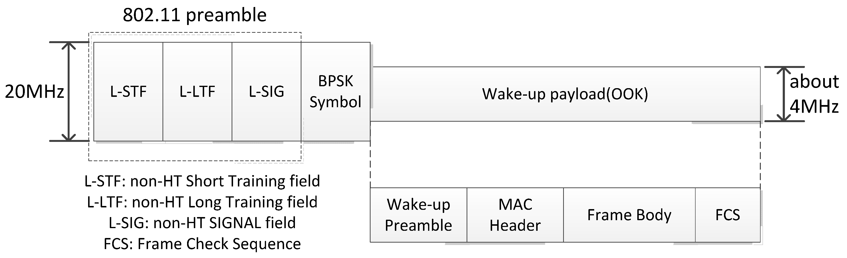
The wake-up frame consists of the legacy IEEE 802.11 preamble, one symbol of binary phase-shift keying (BPSK) signal, and the wake-up payload, as depicted in Figure 2. The legacy IEEE 802.11 preamble and the one symbol of BPSK signal serves to prevent other IEEE 802.11 devices from transmitting packets and causing collisions for the duration of the wake-up frame. The wake-up payload is modulated by OOK, and includes synchronization information, the receiver’s address, and other information. In the standard, it is proposed that the wake-up payload uses the narrower bandwidth channel (about 4 MHz) and has the same transmission range as other IEEE 802.11 devices.
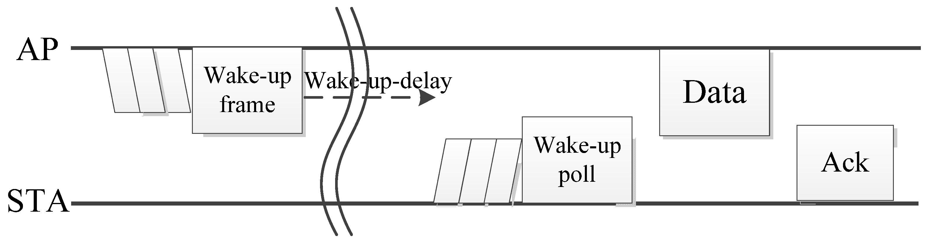
Using the structure of the receiver STA, the transmission procedure in wake-up radio starts with the wake-up frame transmitted by the AP, as in Figure 3. When the AP transmits frames to the STA in the wake-up radio state, the AP sends the wake-up frame before the data packets are transmitted. After the indicated wake-up delay, the STA that receives the wake-up frame may transmit the acknowledgment of the wake-up frame, which is the poll frame, unscheduled automatic power save delivery (U-APSD) trigger frame, etc. After receiving the poll frame from the STA, the AP may start the data transmission. In the case where the response frame of the wake-up frame is not needed, the AP may start transmission of the data frame after the wake-up delay.
In the case of transmission failure, because the AP cannot detect whether the wake-up frame is transmitted successfully, it should send the wake-up frame and again wait for the wake-up delay. However, the long retransmission delay because of the wake-up delay results in poor delay performance of the data transmission, especially in the dense communication environment. In this case, the wake-up delay may be long, as in [20], compared with other transmission procedures.
2.3. IEEE 802.11ax Standard
To achieve high channel efficiency and throughput in dense communication scenarios, the IEEE 802.11ax standard was developed [21]. The main feature of IEEE 802.11ax is MU orthogonal frequency division multiple access (OFDMA) in the uplink and downlink. Using the MU OFDMA procedure, the AP may transmit or receive frames with up to nine STAs for the 20 MHz frequency band.
The uplink MU OFDMA transmission procedure is shown in Figure 4. In the uplink MU OFDMA adopted in IEEE 802.11ax, the AP transmits a trigger frame (TF) to solicit the STA’s MU OFDMA transmission, and indicates a resource unit to be used and the length of the uplink frame. The STAs indicated by the TF use the resource unit to transmit uplink data by uplink multi-user physical layer protocol data unit (UL MU PPDU). The acknowledgment of the uplink data is also done simultaneously with the multi-STA blockack (BA) frame.
2.4. Multiuser Transmission Procedures Using Wake-Up Radio
In the MU case, the conventional transmission procedure causes a large delay and the delay increases as the number of users increases. To reduce the delay in this scenario, optional schemes that meet the different delay and power requirements for multiple wake-up STAs were proposed in [17].
Because the average transmission delay is caused by the repetition of the entire transmission procedure, the options to reduce the average delay are focused on waking up multiple STAs in order to apply MU transmission, as defined in IEEE 802.11ax.
The transmission procedure for the MU scenario consists of sending multiple unicast wake-up frames and waking up all STAs first by broadcast wake-up frame, and then returning them to the sleep state if no frame intended for the STA is received after a predefined time.
3. Target Scenarios for IoT Device in IEEE 802.11ba
The use cases of IEEE 802.11ba include various proposed scenarios of IEEE 802.11ba, including various IoT applications. In [22], scenarios including warehouses, cattle farms, and wearable devices were proposed. In those scenarios, there are a number of sensors that are controlled by a mobile device, which may request the sensed data from all of the sensors, as in Figure 5. For example, in smart-home applications in Figure 6, light sensors, temperature sensors, and door sensors transmit sensed data to a mobile device when the user wants it, and after the user is notified about the information, they may transmit control information to the smart home device to turn off the light, alarm, etc. In those IoT applications, the mobile device needs to acquire data from many sensors.
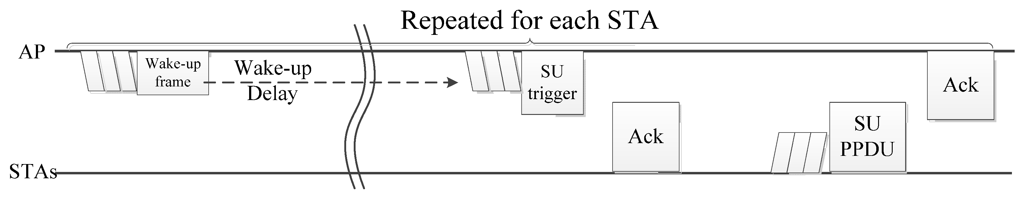
The conventional transmission method for this scenario in IEEE 802.11ba is based on unicast transmission, as shown in Figure 7. With this method, the triggering frame that requests the sensed data from the STA may be implemented in the application layer. When the mobile data needs to collect the sensors’ data, the AP transmits the wake-up frame to the STA, and it then waits for the predefined wake-up delay in the association procedure. After the wake-up delay, the AP starts to transmit the triggering frame of the sensed data, which is denoted as a single-user (SU) trigger, to request the sensed data. The STA that wakes up from the wake-up frame and receives the single-user trigger sends the acknowledgment frame for the single-user trigger and transmits the data in the SU physical layer protocol data unit (PPDU) after a subsequent contention. For the successful transmission of data frames, the AP transmits the acknowledgment of the data frame, and starts the transmission procedure for the next STA.
However, in the conventional transmission procedure in this massive uplink scenario, the transmission delay is increased as the number of STAs increases because of the repetition of the entire procedure for each STA. Therefore, the conventional method based on unicast transmission may not be sufficient to meet the required delay.
4. Proposed System for Massive Uplink Scenario
To reduce the entire transmission delay in a massive uplink scenario, a simple approach in unicast transmission can be to aggregate the acknowledgment frame and data. However, since the transmission procedure is still repeated for each STA, the performance improvement is limited. To reduce the entire delay significantly, the IEEE 802.11ax transmission system can be applied with the wake-up receiver system, as in IEEE 802.11ba, because the wake-up radio in IEEE 802.11ba is supplementary to other IEEE 802.11 radios. In the proposed system, in addition to the conventional IEEE 802.11ax system of the wake-up device, the scheduling scheme for MU operation with wake-up radio and the enhanced distributed channel access (EDCA) parameter set operations are jointly designed. In the joint design of MU scheduling and EDCA parameter setting, the goal of the scheduling operation is to further decrease the data transmission delay in the MU transmission procedure, and the goal of the EDCA parameter operation is to prevent collisions caused by woken-up STAs’ transmissions. The proposed system includes the transmission procedure, as well as a collision-avoidance method which can be used in IEEE 802.11ba.
4.1. Wake-Up Frame and Data Transmission for Triggering Uplink Transmission from Multiple Users
The wake-up and data transmission procedure can be operated in unicast transmission (single-user operation) or multicast transmission (MU operation). In unicast transmission systems, the transmission procedure is repeated for each STA. On the other hand, in the multicast transmission procedure, the transmission procedure is based on a group of STAs, and STAs in the same group may communicate with the AP simultaneously.
4.1.1. Aggregation of Uplink Data with the Acknowledgment of Trigger Frame (Unicast-MAC)
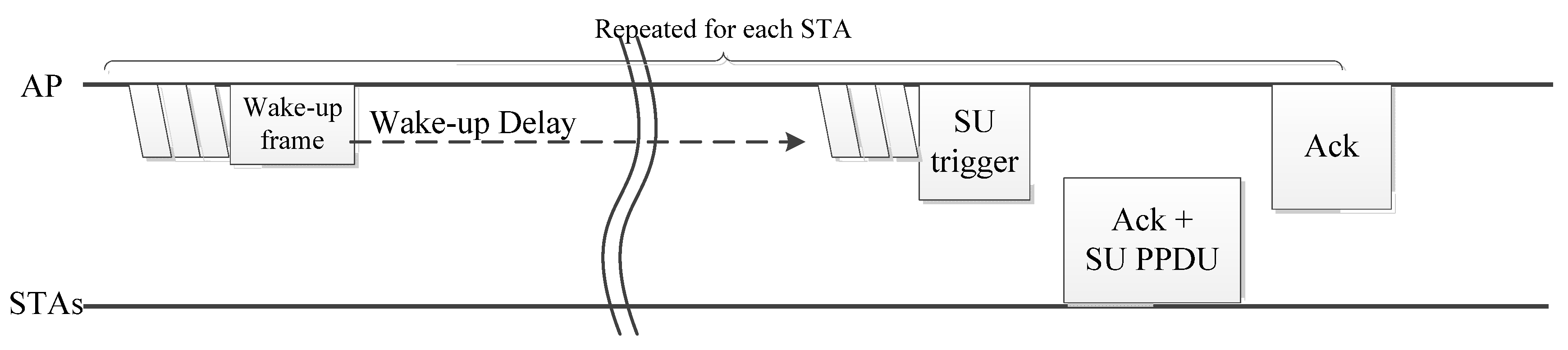
In single-user transmission, the data transmission procedure causes the two-channel access process after the wake-up frame transmission. To reduce the additional contention delay in data transmission, the STA that receives the single-user trigger may respond with an acknowledgment frame aggregated with the data frame, as shown in Figure 8. In this procedure, the single-user trigger includes vendor-specific information to aggregate the acknowledgment frame with the requested data frame. The STA that receives the single-user trigger with the information sends an acknowledgment frame aggregated with the data frame. After the reception of the aggregated frame, the AP sends the acknowledgment frame to indicate reception, and it repeats this procedure for all of the STAs. In this scheme, there is contention for the transmission only when transmitting the single-user trigger, and no additional contention is required to transmit the data frame.
4.1.2. Multi-User Transmission Procedure as in IEEE 802.11ax (Multicast-MAC)
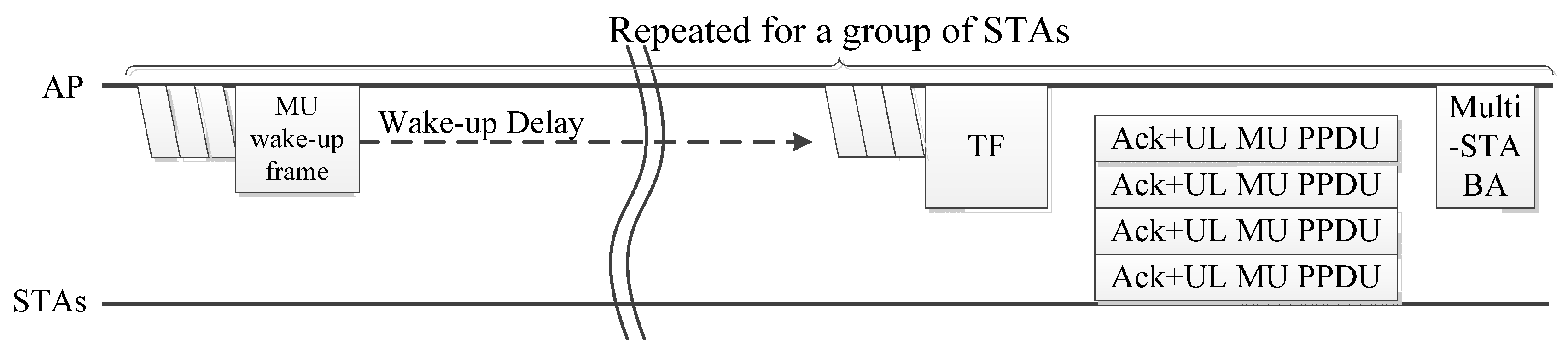
The repetition of the entire transmission procedure causes a large delay as the number of STAs increases, as the long wake-up delay and contention procedures are repeated. In order to reduce the repetition, we can apply the MU transmission procedure adopted in IEEE 802.11ax. As depicted in Figure 9, in the MU transmission with wake-up radio, after the wake-up packet for multiple users is transmitted, the data transmission procedure starts with the TF, as in the uplink MU OFMDA procedure of IEEE 802.11ax. The response of the TF can be a data frame aggregated with the acknowledgment of the TF, as in the unicast-MAC procedure. After the successful reception of the uplink MU OFDMA frame, the AP transmits a multi-STA blockack frame to respond to multiple STAs simultaneously.
This procedure reduces the delay in the entire transmission procedure simultaneously, but the AP continuously waits for the wake-up delay for each transmission procedure. Because the wake-up delay is longer than other transmission delays, the repetition involved in waiting for a wake-up delay is inefficient.
4.1.3. Scheduled Operation for IoT Devices (Multicast-Scheduled)
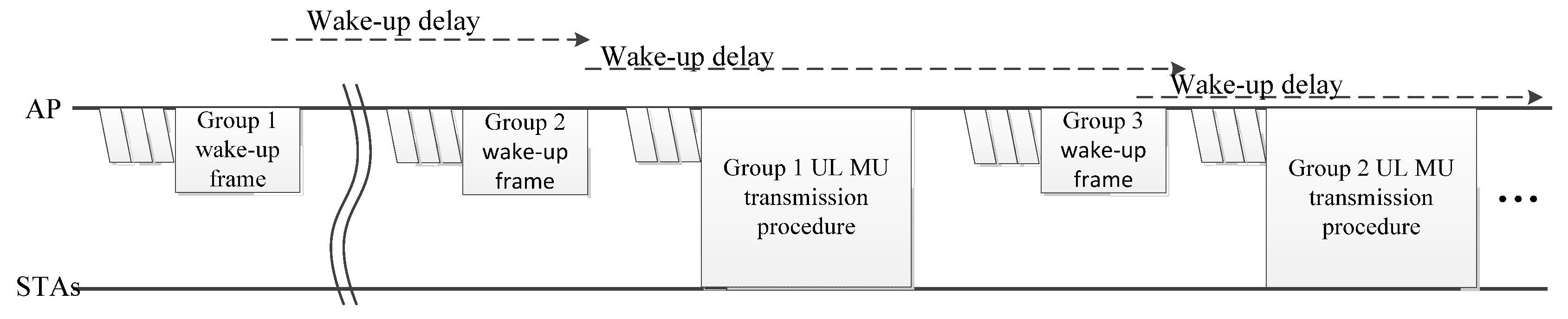
Although MU transmission reduces the transmission delay significantly, the repetition of the entire transmission procedure results in a large end-to-end delay because the AP waits for a long wake-up time in each group. To reduce the inefficiency due to the wake-up delay, the AP may transmit a wake-up packet to another group during the wake-up delay. In this scheme, as in Figure 10, the AP schedules the MU data transmission procedure of the previous group and the wake-up packet of the next group in the wake-up delay. For example, in Group 2’s wake-up delay, the data transmission procedure of Group 1 and wake-up frame to Group 3 are scheduled. Using the scheduling procedure, the wake-up delay of each group is cascaded and the entire data transmission delay can be reduced.
4.2. Discussion on the Wake-Up Frame Format for Multi-User Operation
To apply the MU transmission procedure as described in previous section, there is a need to wake up multiple STAs. In addition to the proposed methods in [17], there are some recent proposals for the MU wake-up frame format in IEEE 802.11ba, although it is still under standardization. In [23], the MU format of the wake-up frame is proposed. Because the wake-up frame consists of a 20-MHz IEEE 802.11 preamble and a narrow-band wake-up payload, the wake-up payload may be transmitted in a frequency-division multiple access (FDMA) OOK signal, as depicted in Figure 11. To apply this wake-up frame structure in the association procedure, STAs should negotiate the frequency band on which to receive the wake-up packet with the AP. After the negotiation, wake-up receivers in STAs only need to scan the predetermined band in order to receive the wake-up packet. Another proposal for the MU wake-up frame [24] is to use a group identifier (ID) in the receiver address field. The group ID should be negotiated with the AP when the STA is associated or when it switches to the wake-up mode. To use the group ID, the grouping method is important, because there may be unnecessary wake-up procedures, which causes power wastage.
4.3. EDCA Parameters for Multiple STA Operation
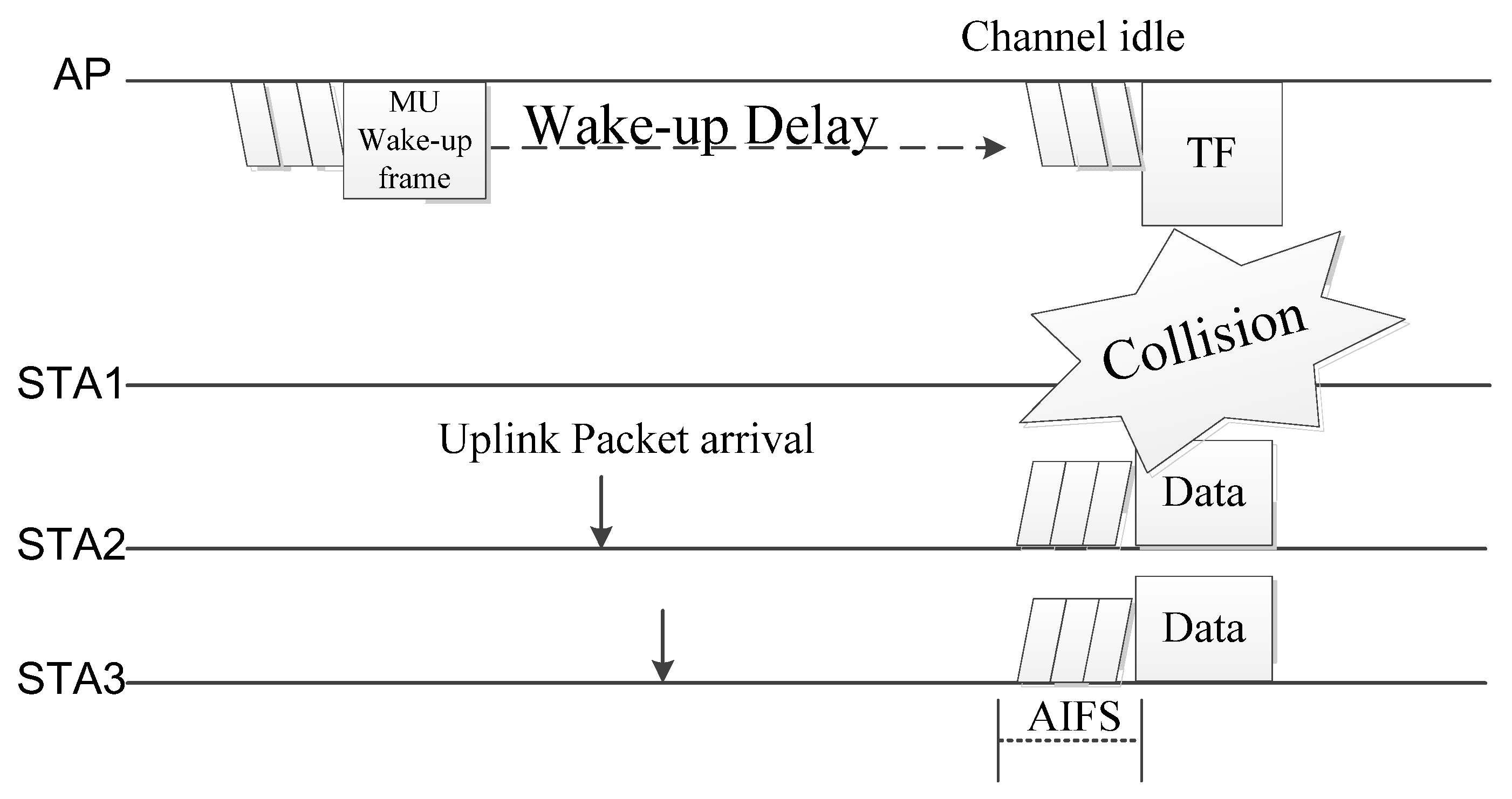
The MU transmission procedure reduces the end-to-end delay of the entire transmission, but it also increases the collision probability as the number of STAs in the MU OFDMA procedure increases. As depicted in Figure 12, each STA may have an uplink packet arrival, and the contention procedure is operated when there is an uplink packet in the STA during the wake-up delay. Because in WLAN transmissions procedure with EDCA, the STA may start to transmit the data when the channel is idle for the arbitration inter-frame spacing (AIFS) period, there is a high probability that there will be collisions.
Collisions in the wake-up receiver procedure cause severe degradation in terms of power efficiency because the AP should then restart the wake-up frame transmission. In particular, if the TF encounters a collision, STAs in the MU transmission procedure remain in an idle state and wait for the wake-up frame and subsequent TF for the long wake-up delay.
To prevent collisions, a shorter AIFS can be applied to the TF, which gives high priority to the transmission of TF. By implementing the short AIFS for the TF, STAs that have uplink data defer their transmissions, which reduces the probability of collisions. The implementation of a short AIFS parameter in the MU TF is possible using the EDCA parameters determined by the AP because the IEEE 802.11ax standard enables the AP to decide the EDCA parameter of each access category (AC), and the trigger frame can use any access category to access the channel.
5. Delay and Power Analysis
5.1. Delay Analysis
In the delay analysis, there are N nodes that request and receive the sensed data. We analyzed the average delay of the entire transmission: from when the AP requests to gather the sensed data from each sensor to when the AP collects the data from all of sensors. When the average delay is calculated, the average contention delay E[Tcontention] depends on the background traffic of other IEEE 802.11 devices’ transmissions. In this paper, the contention delay is assumed to be calculated as in [25], when the number of STA in the background traffic and inter-arrival time are applied. When the average contention delay of wake-up packet transmission E[Tcontention-wupkt] is derived, the wake-up delay Twudelay and the subsequent triggering frame transmission delay are included in the collision delay, because AP detects the collision after it receives no response for the triggering frame, which is a single-user trigger or TF. Similarly, in the case of deriving the contention delay of single-user trigger E[Tcontention-SUtrig] or multi-user trigger E[Tcontention-MUtrig] frames, the transmission delay of the wake-up packet and Twudelay are included in the collision delay, because the retransmission of the wake-up packet is needed. On the other hand, Twudelay is not included in the collision delay of the data frame E[Tcontention-Data] in the conventional transmission method, because AP knows that STA is in the awake state by receiving the acknowledgement frame of the single-user trigger.
In the conventional method, the average transmission delay is N times the transmission delay for each STA. In the average contention delay, the collision delay includes the wake-up delay caused by the retransmission of the wake-up frame in the contention for the wake-up packet and single user frame when it is excluded in the contention for data transmission. This is because no wake-up frame retransmission is required for the data frame transmission failure. The collision probability of the wake-up packet transmission and triggering frame transmission is also different, because if the packet arrives at the STA during the wake-up delay, the STA may transmit the packet at the same time as the AP’s transmission for idle channels. Therefore, the average transmission delay in conventional method is:
where TSUWUpkt, TSUtrigger, and TSUData denote the transmission delay of the single-user wake-up packet, the single-user trigger, and the data frame respectively.
E[Tconventional] = N(E[Tcontention-wupkt] + E[Tcontention-SUtrig] + E[Tcontention-Data] + Twudelay + TSUWUpkt + TSUtrigger + TSUData + 2Tack + 2SIFS)
In the unicast-MAC method, the acknowledgment frame for the triggering frame and the data frame are aggregated, and the contention for the data frame is not processed.
Therefore, the average transmission delay is:
where TAck+SUData denotes the transmission delay of the acknowledgement of single user trigger aggregated with the data frame.
E[TSU_MAC] = N(E[Tcontention-wupkt] + E[Tcontention-SUtrig] + Twudelay + TSUWUpkt + TSUtrigger + TAck+SUData + 2Tack + 2SIFS)
In the multicast-MAC procedure, we assume nine user transmissions in a group because the uplink MU OFDMA procedures in IEEE 802.11ax enables up to nine user transmissions in the 20-MHz band. In MU transmissions, the contention delay is also different from that of single-user transmissions because of the larger collision probability of the TF, which increases as the number of STAs in the MU transmission procedure increases. If the extended inter-frame space (EIFS) parameter operation is applied, the contention collision probability of the MU TF is significantly reduced, which affects the contention delay of the MU trigger delay.
Therefore, the average delay for the multicast-MAC transmission procedure is:
where TMUWUpkt, TMUtrigger, TMU_Data+ack, and TMU-ack denote the transmission delay of the multicast wake-up frame, the TF, the data frame aggregated with the acknowledgement frame in uplink multi-user transmission, and the multi-STA blockack frame respectively.
In the multicast-scheduled procedure, because data frame transmissions and the wake-up packet transmission are operated, the delay for gathering the data from all STAs is further reduced. Therefore, the average delay is a modified form of the multicast-MAC procedure, which is:
with the following condition:
where E[Tint_transmission] is the average interval of the transmission procedure. E[Tint_transmission] depends on the scheduling procedure in AP, where each transmission interval Tint_transmission is smaller than Twudelay.
E[Tcontention-wupkt] + E[Tcontention-MUtrig] + TMUWUpkt + TMUtrigger + TMU_Data+ack + TMU-ack < Twudelay
5.2. Power Analysis
We calculated the power consumption for each STA only for triggering the uplink data and transmission procedure. In the analysis, E[Cpkt-type] indicates the average number of collisions for each packet type, which is the reciprocal number of the collision probability. The analysis ignores the power consumption during the wake-up receiver operation because it is negligible compared to the power consumption in the main transceiver.
The average power consumption in the STA for the conventional method is based on:
where
where denotes the setup power, denotes the transition power of transmission state and receiving state, is the transmission power, and is the receiving power.
In the unicast-MAC method, there is no contention procedure for the data frame transmission, and the power consumed for this contention is reduced. Therefore, the power consumption of STA for the uplink transmission procedure in the unicast-MAC method is:
where
In the multicast-MAC and multicast-scheduled procedure, the frame length of the MU transmission is longer than that for single-user frames. In addition, the contention delay and average number of contentions for MU TF are different from those of single-user transmissions, as described in the delay analysis. The transmission power of the STA in MU transmission is different because it uses a smaller bandwidth than single user transmission. Therefore, the average power consumption in each STA is:
where
6. Simulation Results and Discussion
6.1. Simulation Environment
In the simulation, we assumed that there were 100 STAs associated with the AP. Each STA produced a data packet for single-user uplink transmission, with the inter-arrival time following an exponential distribution mean value TD. When the AP needed to collect the data from N users, the transmission procedure to request and receive the sensor data began. The transmission procedure was performed until the data from all N users were received successfully.
The power consumption in each STA was measured only when the wake-up and transmission procedure for that STA was processed. For the MU transmission case, the transmission power was assumed to be similar to that of the single-user case. Other parameters are described in Table 2.
6.2. Simulation Results
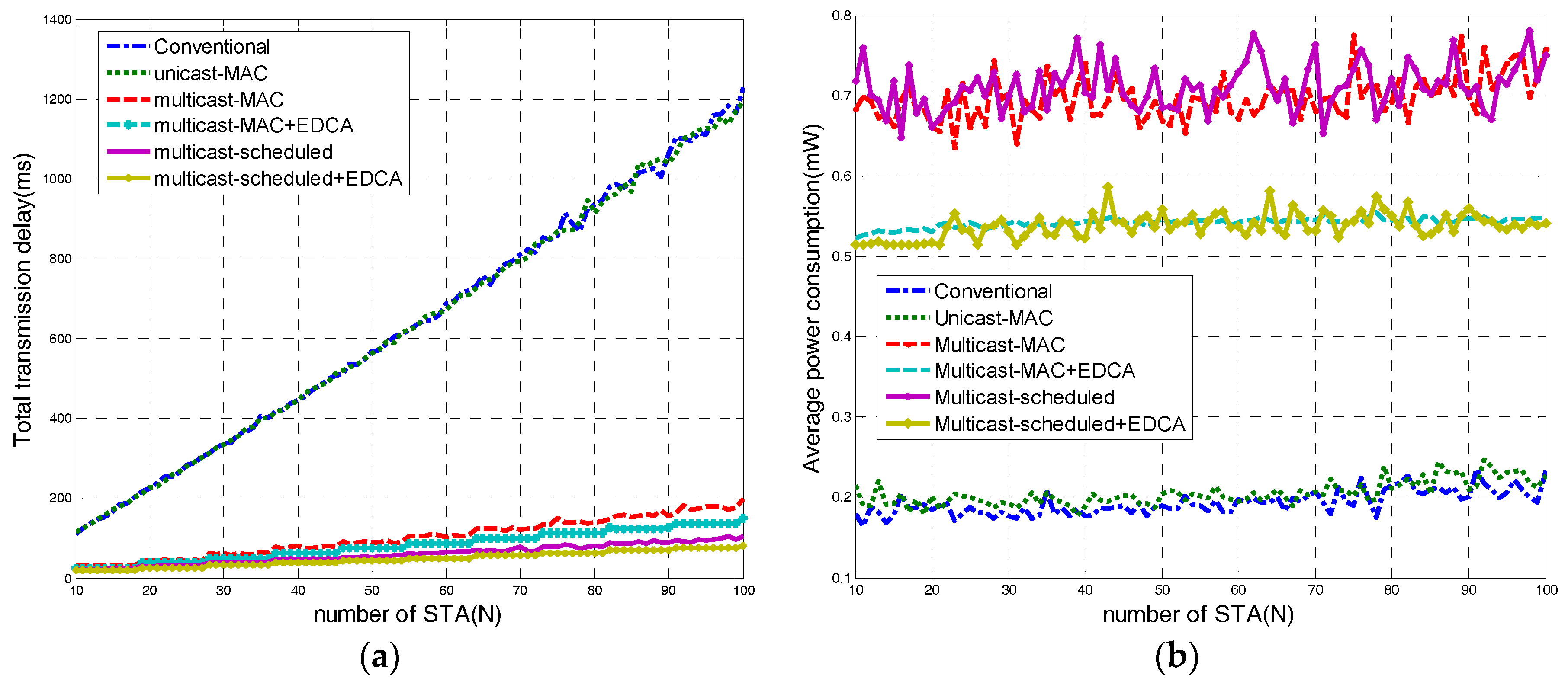
The measured delay of the transmission is depicted in Figure 13a. In the single-user transmission, the total delay to obtain the data from all STAs increased linearly as the number of STA increased. The rapid increase in the delay as the number of STAs increased is because of the repetition of the wake-up delay which the AP waited for the STA to wake up without processing other transmissions with regards to the procedure for obtaining the sensed data. There was little difference in the total transmission delays for the conventional method and unicast-MAC method. This is because the delay was mainly caused by the wake-up delay and the triggering frame transmission failure where the AP needed to retransmit the wake-up packet. Therefore, the effect of the contention delay for data packets appears to be limited.
The MU transmission significantly reduced the transmission delay because the wake-up delay was reduced as the transmission procedure was done with multiple STA simultaneously. In addition to the MU operation as in IEEE 802.11ax, the implementation of the scheduling scheme further reduced the transmission delay as it utilized the wake-up delay in the transmission procedure of the data packet and the wake-up packet addressed to other STAs. The difference between the multicast-MAC scheme and the multicast-scheduled scheme increased as the number of STA increased. In the case of 100 STAs, the delay of the multicast-scheduled scheme was more than 40% smaller than the delay of the multicast-MAC scheme. The modification of the EDCA parameter in the TF also reduced the delay. This is because collisions of TFs resulted in a long wake-up delay because of the need to retransmit the wake-up frame to the corresponding STAs.
From the perspective of the power consumption in each STA, the measured power was independent of the number of STAs, as shown in Figure 13b. The average power consumption in the MU transmission was higher because the length of the uplink data frame was increased significantly, as multiple STAs transmitted the frame simultaneously in the same bandwidth. In addition, the collision probability of the TF increased for MU transmission, which degraded the power efficiency. By adopting the modification of the EDCA parameter, the consumed power can be reduced in the MU transmission procedure.
6.3. Discussion on the Strengths and Weaknesses of the Proposed Scheme
The main strength of the proposed scheme is that it efficiently reduces the overall delay for the massive uplink transmissions of IoT devices with a wake-up receiver in IEEE 802.11ba. The overall delay reduction of massive uplink transmission can be achieved with the joint design of the UL MU OFDMA and wake-up receiver of the proposed scheme. The proposed group transmission scheduling scheme and modified EDCA parameters also provide more delay reduction and power reduction when they are working together with UL MU OFDMA.
The main weakness of the proposed scheme is that it increases power consumption. In the case of UL MU OFDMA, power consumption increased due to increased packet transmission time by using the narrow band uplink channels. Moreover, if STAs have additional uplink data after performing UL MU OFDMA transmission in massive uplink transmission, they need to perform contention procedures for channel access, which results in increased collision probability leading to more power consumption for the additional transmission.
7. Conclusions
In this paper, the joint design of wake-up radio in IEEE 802.11ba and the uplink MU OFDMA procedure in IEEE 802.11ax has been proposed. The wake-up radio operation with a low-power operating wake-up receiver resolves the trade-off problem between power consumption and latency in duty-cycle operation of low-power communication method. In the case of a dense communication environment in massive uplink scenario, unicast transmission may not be able to meet the Quality of Service (QoS) requirements of the data, because transmission delay increases linearly as the number of STAs increases. The proposed approach of MU transmission in wake-up radio significantly reduces total transmission delay for large number of users. In addition, the scheduling method and modifying EDCA parameter for the TF reduces the total transmission delay further. However, because of the longer frame duration, the power consumption increases, as we assumed the same power consumption for different bandwidths. Moreover, waking up multiple STAs for uplink MU transmission results in increased collision probability, because the STAs may attempt to access the channel simultaneously. Although the consumed power is increased, the effect of power wastage owing to collisions is limited because of the modified EDCA operation. The simulation results verify these points.
The proposed scheme provides delay-efficient communications in IoT applications that are based on the dense communication scenario, with low-power performance degradation. In particular, when the mobile device needs to acquire the sensed data from the massive number of sensors, the delay performance of the proposed scheme outperforms that of the conventional transmission procedure. With the proposed transmission scheme using wake-up radio operation in IEEE 802.11ba, the AP may select the proper transmission procedure depending on the traffic and density of associated STAs, which enables the dynamic management of delay and power consumption of STAs. In the next generation IoT networks, where various types of IoT devices with various applications concurrently operate and massive uplink transmission is norm, it is anticipated that the proposed scheme will play an important role in power saving in battery powered IoT devices with reduced delay.
Acknowledgments
This research was supported by Basic Science Research Program through the National Research Foundation of Korea (NRF), and funded by the Ministry of Science, ICT & Future Planning (NRF-2017R1A2B4003987).
Author Contributions
Hanseul Hong, Young Yong Kim, and Ronny Yongho Kim conceived the study. Hanseul Hong and Ronny Yongho Kim did the literature review. Hanseul Hong designed the model, collected the simulation results, and analyzed the performance. Hanseul Hong, Young Yong Kim, and Ronny Yongho Kim wrote the paper. Ronny Yongho Kim supervised the whole study. All authors reviewed and approved the manuscript.
Conflicts of Interest
The authors declare no conflict of interest.
References
- Varshney, L.R. Transporting information and energy simultaneously. In Proceedings of the 2008 IEEE International Symposium on Information Theory, Toronto, ON, Canada, 6–11 July 2008; pp. 1612–1616. [Google Scholar] [CrossRef]
- Mekikis, P.-V.; Antonopoulos, A.; Kartsakli, E.; Lalos, A.S.; Alonso, L.; Verikoukis, C. Information exchange in randomly deployed dense WSNs with wireless energy harvesting capabilities. IEEE Trans. Wirel. Commun. 2016, 15, 3008–3018. [Google Scholar] [CrossRef]
- Sun, Y.; Du, S.; Gurewitz, O.; Johnson, D.B. DW-MAC: A low latency, energy efficient demand-wakeup MAC protocol for wireless sensor networks. In Proceedings of the MobiHoc’08 9th ACM International Symposium on Mobile Ad Hoc Networking and Computing, Hong Kong, China, 26–30 May 2008; pp. 53–62. [Google Scholar] [CrossRef]
- Sun, Y.; Gurewitz, O.; Johnson, D.B. RI-MAC: A receiver-initiated asynchronous duty cycle MAC protocol for dynamic traffic loads in wireless sensor networks. In Proceedings of the SenSys’08 6th ACM Conference on Embedded Network Sensor Systems, Raleigh, NC, USA, 4–7 November 2008; pp. 1–14. [Google Scholar] [CrossRef]
- Tang, L.; Sun, Y.; Gurewitz, O.; Johnson, D.B. PW-MAC: An energy-efficient predictive-wakeup MAC protocol for wireless sensor networks. In Proceedings of the 2011 IEEE INFOCOM, Shanghai, China, 10–15 April 2011; pp. 1305–1313. [Google Scholar] [CrossRef]
- Collotta, M.; Pau, G. A novel approach to improve power management in wireless local area networks. Int. J. Ad Hoc Ubiquitous Comput. 2016. [Google Scholar] [CrossRef]
- Khan, M.; Silva, B.N.; Han, K. Internet of Things based energy aware smart home control system. IEEE Access 2016, 4, 7556–7566. [Google Scholar] [CrossRef]
- Antonopoulos, A.; Alonso-Zárate, J.; Kartsakli, E.; Alonso, L.; Verikoukis, C. Cross layer access point selection mechanisms for a distributed queuing MAC protocol. Telecommun. Syst. 2013, 53, 329–342. [Google Scholar] [CrossRef]
- Jones, V.; Sampath, H. Emerging technologies for WLAN. IEEE Commun. Mag. 2015, 53, 141–149. [Google Scholar] [CrossRef]
- Institute of Electrical and Electronics Engineering (IEEE). Wireless LAN Medium Access Control (MAC) and Physical Layer (PHY) Specifications Amendment 2: Sub 1 GHz License Exempt Operation; IEEE: Piscataway, NJ, USA, 2017. [Google Scholar] [CrossRef]
- Pletcher, N.M.; Gambini, S.; Rabaey, J. A 2 GHz 52 μW wake-up receiver with −72 dBm sensitivity using an uncertain-IF architecture. IEEE J. Solid-State Circuits 2009, 44, 269–280. [Google Scholar] [CrossRef]
- Hambeck, C.; Mahlknecht, S.; Herndl, T. A 2.4 µW wake-up receiver for wireless sensor nodes with −71 dBm sensitivity. In Proceedings of the 2011 IEEE International Symposium of Circuits and Systems (ISCAS), Rio de Janeiro, Brazil, 15–18 May 2011; pp. 534–537. [Google Scholar] [CrossRef]
- Salazar, C.; Kaiser, A.; Catherlin, A.; Rabaey, J. 13.5 A −97 dBm-sensitivity interferer-resilient 2.4 GHz wake-up receiver using dual-IF multi-N-Path architecture in 65 nm CMOS. In Proceedings of the 2015 IEEE International Solid-State Circuits Conference (ISSCC) Digest of Technical Papers, San Francisco, CA, USA, 22–26 February 2015; pp. 1–3. [Google Scholar] [CrossRef]
- Le-Huy, P.; Roy, S. Low-Power 2.4 GHz wake-up radio for wireless sensor networks. In Proceedings of the 2008 IEEE International Conference on Wireless and Mobile Computing, Networking and Communications, Avignon, France, 12–14 October 2008; pp. 13–18. [Google Scholar] [CrossRef]
- Miller, M.J.; Vaidya, N.H. A MAC protocol to reduce sensor network energy consumption using a wakeup radio. IEEE Trans. Mobile Comput. 2005, 4, 228–242. [Google Scholar] [CrossRef]
- Mazloum, N.S.; Edfors, O. DCW-MAC: An energy efficient medium access scheme using duty-cycled low-power wake-up receivers. In Proceedings of the 2011 IEEE Vehicular Technology Conference (VTC Fall), San Francisco, CA, USA, 5–8 September 2011; pp. 1–5. [Google Scholar]
- Hong, H.; Kim, Y.Y.; Kim, R.Y.; Hwang, S.; Park, S. A novel low power WLAN operation scheme for multiple wake-up receivers. In Proceedings of the 2017 IEEE International Conference on Consumer Electronics (ICCE), Las Vegas, NV, USA, 8–10 January 2017; pp. 333–334. [Google Scholar] [CrossRef]
- Xie, S.; Wang, Y. Construction of tree network with limited delivery latency in homogeneous wireless sensor networks. Wirel. Pers. Commun. 2014, 78, 231–246. [Google Scholar] [CrossRef]
- Azizi, S.; Park, M.; Aboul-Magd, O.; Shellhammer, S.; Wilhelmsson, L.; Carney, W.; Rison, M.; Son, J.; Mori, K.; Cheong, M.; et al. A PAR Proposal for Wake-up Radio. IEEE 802.11-16/1045r7. Available online: https://mentor.ieee.org/802.11/dcn/16/11-16-1045-07-0wur-a-par-proposal-wur-sg.docx (accessed on 23 October 2017).
- Marlin, S.; Barriac, G.; Sampath, H.; Cariou, L.; Derham, T.; Le Rouzic, J.-P.; Stacey, R.; Park, M.; Ghosh, C.; Porat, R.; et al. TGax Simulation Scenarios. IEEE 802.11-14/0980r16. Available online: https://mentor.ieee.org/802.11/dcn/14/11-14-0980-16-00ax-simulation-scenarios.docx (accessed on 23 October 2017).
- Institute of Electrical and Electronics Engineering (IEEE). P802.11ax/D1.0—Wireless LAN Medium Access Control (MAC) and Physical Layer (PHY) Specifications—Amendment 6: Enhancements for High Efficiency WLAN; IEEE: Piscataway, NJ, USA, 2016. [Google Scholar]
- Yu, R.; Yang, D.; Han, Y.; Cheng, Y.; Fang, P.; Ding, Z.; Shilo, S.; Weitzman, A.; Tsodik, G.; Yang, Y.; et al. WUR Use Cases and Requirements. IEEE 802.11-17/0029r10. Available online: https://mentor.ieee.org/802.11/dcn/17/11-17-0029-10-00ba-wur-usage-model-document.pptx (accessed on 23 October 2017).
- Liu, J.; Wu, T.; Huang, R.; Pare, T.; Wang, J. On Waking-Up Multiple WUR Stations. IEEE 802.11-17/0028r0. Available online: https://mentor.ieee.org/802.11/dcn/17/11-17-0028-00-00ba-on-waking-up-of-multiple-wur-stations.pptx (accessed on 23 October 2017).
- Kim, J.; Ryu, K.; Park, J.; Kim, S.; Choi, J. WUR MAC Issues. IEEE 802.11-17/0054r3. Available online: https://mentor.ieee.org/802.11/dcn/17/11-17-0054-03-00ba-wur-mac-issus.pptx (accessed on 23 October 2017).
- Zhao, Q.; Tsang, D.H.K.; Sakurai, T. A simple approximate model for nonsaturated IEEE 802.11 DCF. IEEE Trans. Mobile Comput. 2009, 8, 1539–1553. [Google Scholar] [CrossRef]
Figure 1.
Structure of the Wake-up radio device. Ack = acknowledgment.
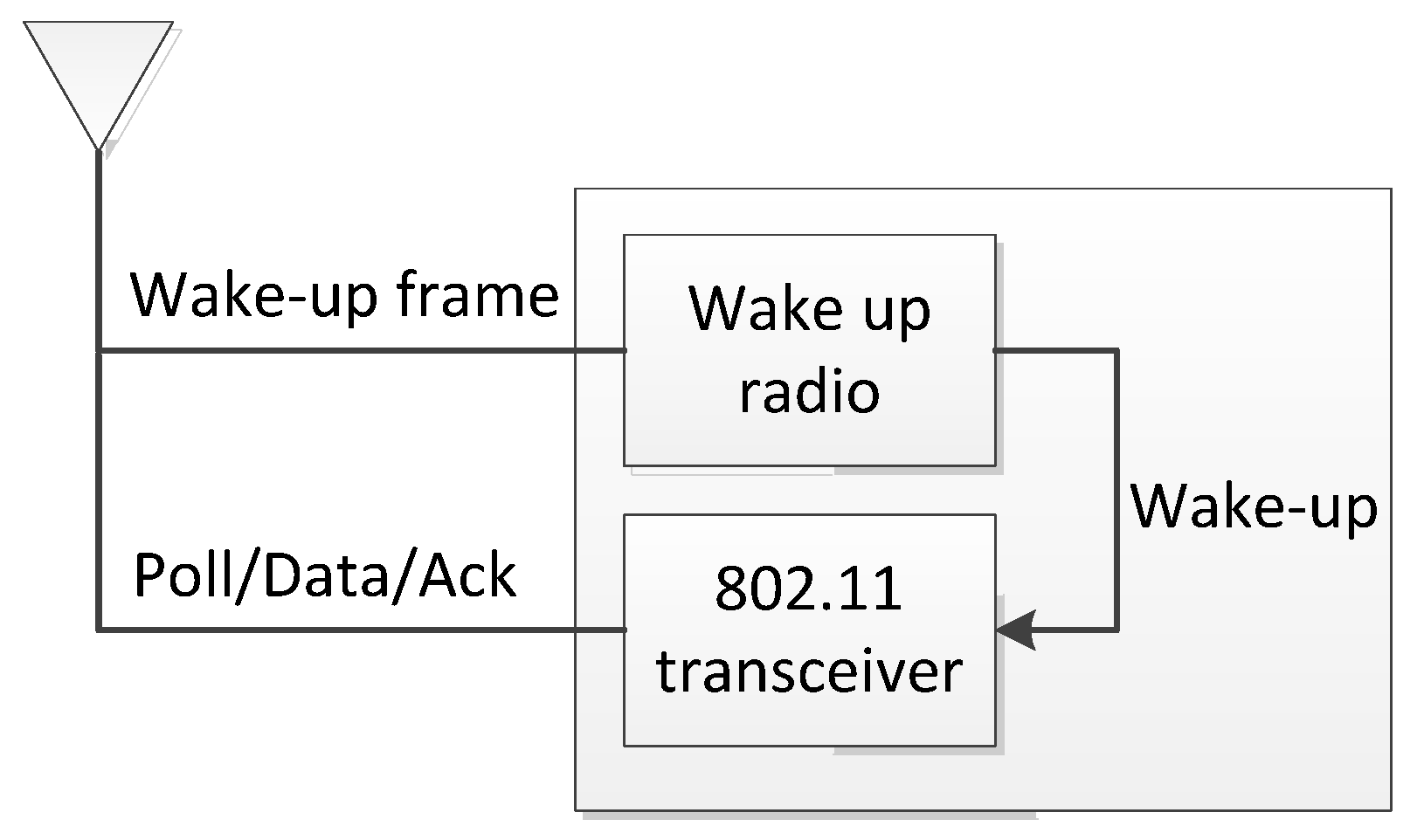
Figure 2.
Structure of Wake-up symbol. BPSK = Binary Phase-shift Keying; MAC = Medium Access Control; HT = High Throughput.
Figure 2.
Structure of Wake-up symbol. BPSK = Binary Phase-shift Keying; MAC = Medium Access Control; HT = High Throughput.

Figure 3.
Wake-up radio transmission procedure in IEEE 802.11ba. STA = station; AP = Access Point.

Figure 4.
Uplink multiuser OFDMA procedure in accordance with IEEE 802.11ax. TF = trigger frame; Multi-STA BA = multi-station blockack; UL MU PPDU = uplink multi-user physical layer protocol data unit.
Figure 4.
Uplink multiuser OFDMA procedure in accordance with IEEE 802.11ax. TF = trigger frame; Multi-STA BA = multi-station blockack; UL MU PPDU = uplink multi-user physical layer protocol data unit.
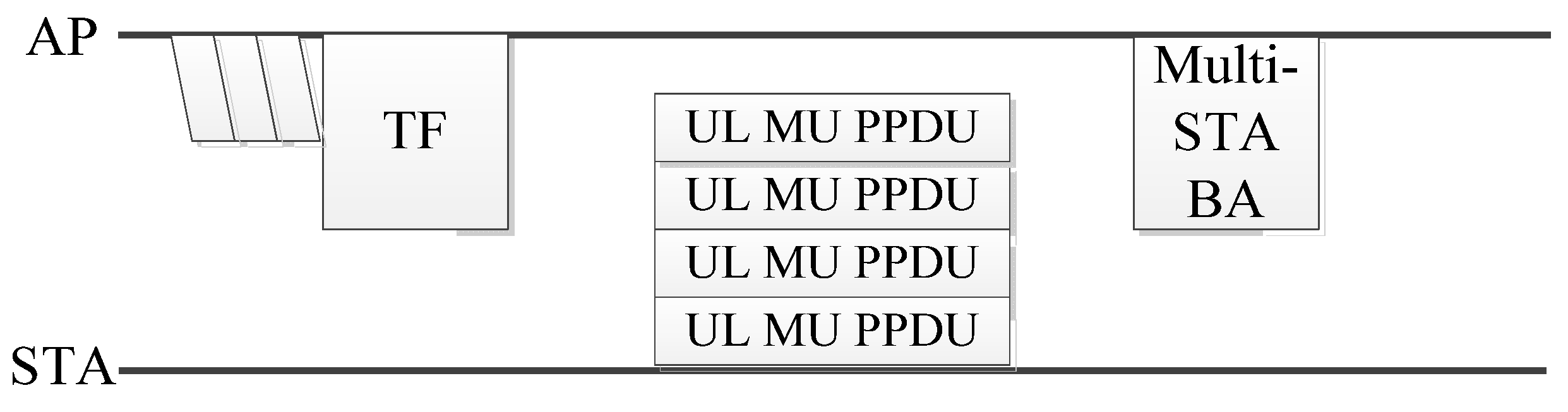
Figure 5.
Massive uplink scenario for an Internet of Things (IoT) device.
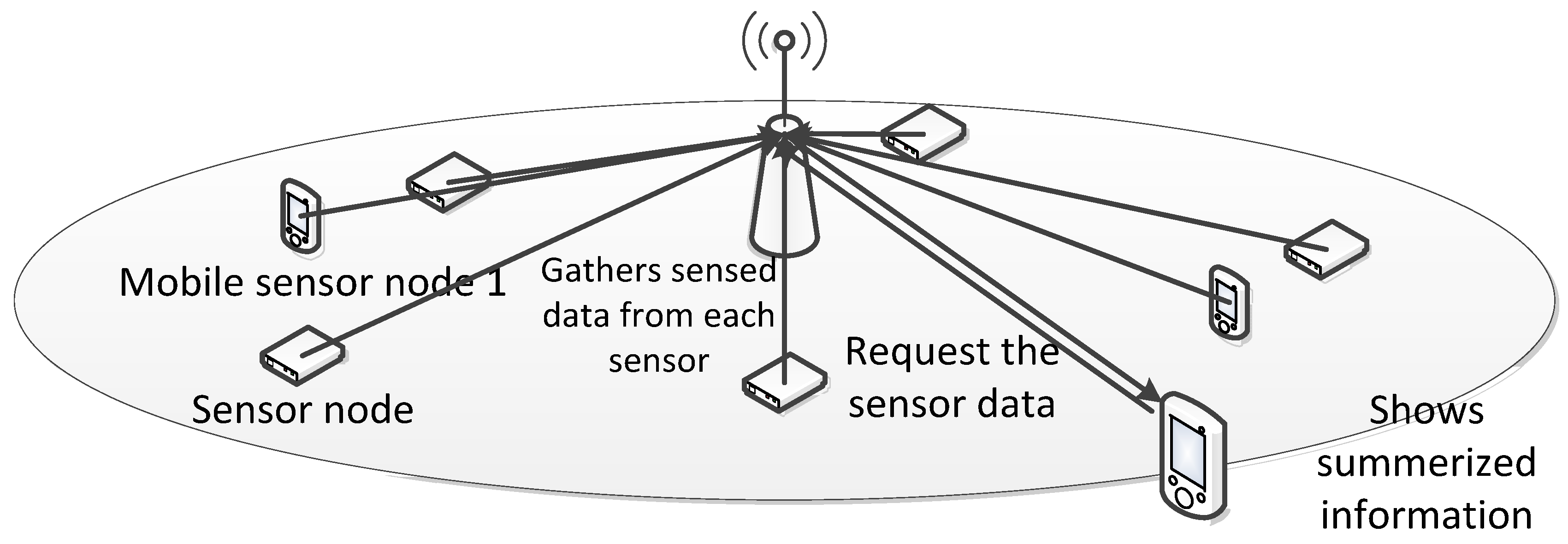
Figure 6.
One of IEEE 802.11ba scenarios: the smart home.
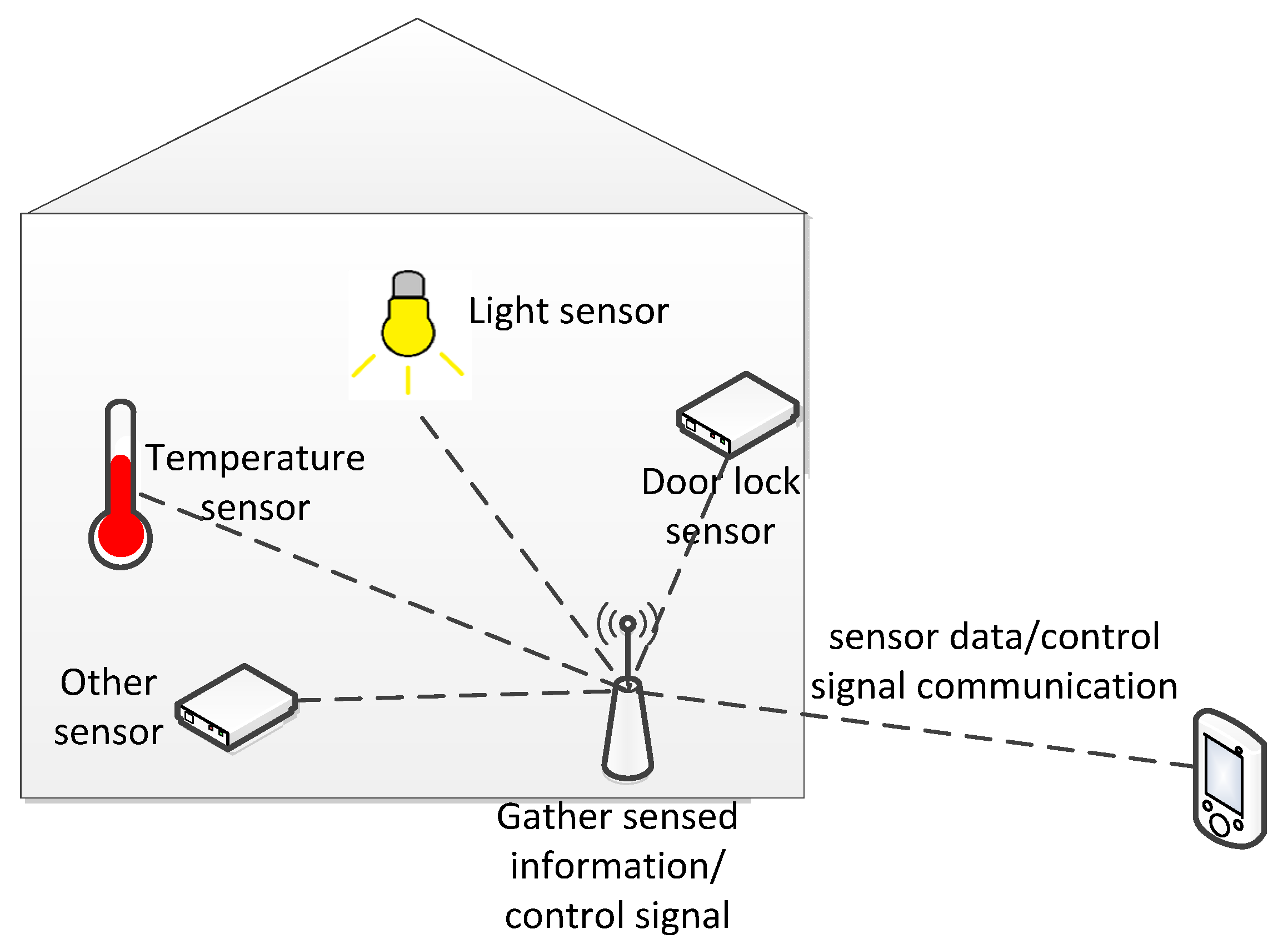
Figure 7.
Data transmission procedure to gather the sensed data from sensors operated in application layer based on unicast transmission. SU = single user; SU PPDU = single user physical layer protocol data unit.
Figure 7.
Data transmission procedure to gather the sensed data from sensors operated in application layer based on unicast transmission. SU = single user; SU PPDU = single user physical layer protocol data unit.

Figure 8.
Data transmission procedure to gather the sensed data from sensors operated in MAC layer based on unicast transmission.
Figure 8.
Data transmission procedure to gather the sensed data from sensors operated in MAC layer based on unicast transmission.

Figure 9.
Normal uplink multiuser transmission using wake-up packet for multiple user.

Figure 10.
Scheduled uplink multiuser transmission using wake-up packet for multiple user. UL MU = uplink multi-user.
Figure 10.
Scheduled uplink multiuser transmission using wake-up packet for multiple user. UL MU = uplink multi-user.

Figure 11.
Multiuser format of wake-up frame.
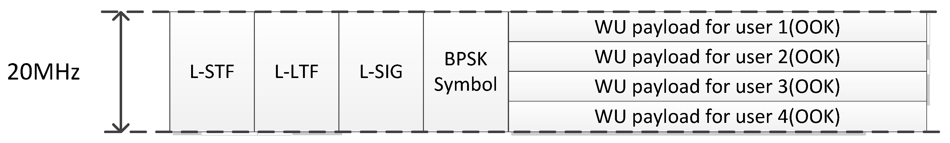
Figure 12.
Collision case in multiuser wake-up procedure. MU = multi-user; AIFS = arbitration inter-frame spacing.
Figure 12.
Collision case in multiuser wake-up procedure. MU = multi-user; AIFS = arbitration inter-frame spacing.

Figure 13.
The total transmission delay and average power consumption as the number of STA increased. (a) Total transmission delay; (b) average power consumption. EDCA = enhanced distributed channel access.
Figure 13.
The total transmission delay and average power consumption as the number of STA increased. (a) Total transmission delay; (b) average power consumption. EDCA = enhanced distributed channel access.

Table 1.
Properties of developed wake-up receivers. OOK = On-Off Keying. PWM = Pulse Width Modulation.
Table 1.
Properties of developed wake-up receivers. OOK = On-Off Keying. PWM = Pulse Width Modulation.
| Reference | Frequency (GHz) | Modulation | Sensitivity (dBm) | Data Rate (Kbps) | Power Consumption (μW) |
|---|---|---|---|---|---|
| [11] | 2 | OOK | −72 | 100 | 52 |
| [12] | 868 | OOK | −71 | 20–200 | 2.4 |
| [13] | 2.4 | OOK | −97/−92 | 10/50 | 99 |
| [14] | 2.4 | PWM | −50 | 50 | 19 |
Table 2.
Simulation Parameters. Tx = Transmit.
| Symbol | Name of Parameter | Value |
|---|---|---|
| TWUdelay | wake-up delay | 10 ms |
| B | number of data bits | 1000 bit |
| PTX_single | Tx power for single user transmission | 280 mW |
| PTX_mu | Tx power for multiuser transmission | 280 mW |
| PRX | receive power | 100 mW |
| Plisten | power for idle listening | 50 mW |
| PST | setup power | 5 mW |
| TD | mean inter-arrival time of packet | 100 ms |
© 2018 by the authors. Licensee MDPI, Basel, Switzerland. This article is an open access article distributed under the terms and conditions of the Creative Commons Attribution (CC BY) license (http://creativecommons.org/licenses/by/4.0/).
Share and Cite
MDPI and ACS Style
Hong, H.; Kim, Y.Y.; Kim, R.Y. A Low-Power WLAN Communication Scheme for IoT WLAN Devices Using Wake-Up Receivers. Appl. Sci. 2018, 8, 72. https://doi.org/10.3390/app8010072
AMA Style
Hong H, Kim YY, Kim RY. A Low-Power WLAN Communication Scheme for IoT WLAN Devices Using Wake-Up Receivers. Applied Sciences. 2018; 8(1):72. https://doi.org/10.3390/app8010072
Chicago/Turabian StyleHong, Hanseul, Young Yong Kim, and Ronny Yongho Kim. 2018. "A Low-Power WLAN Communication Scheme for IoT WLAN Devices Using Wake-Up Receivers" Applied Sciences 8, no. 1: 72. https://doi.org/10.3390/app8010072
Note that from the first issue of 2016, this journal uses article numbers instead of page numbers. See further details here.