Article

New Insights in the Ion Beam Sputtering Deposition of ZnO-Fluoropolymer Nanocomposites

1
Dipartimento di Chimica, Università degli Studi di Bari “Aldo Moro”, via E. Orabona 4, Bari 70126, Italy
2
Dipartimento Interateneo di Fisica, Università degli Studi di Bari “Aldo Moro”, via Amendola 173, Bari 70126, Italy
3
INFN-Sezione di Bari, via E. Orabona 4, Bari 70126, Italy
*
Author to whom correspondence should be addressed.
Appl. Sci. 2018, 8(1), 77; https://doi.org/10.3390/app8010077
Submission received: 4 December 2017 / Revised: 21 December 2017 / Accepted: 31 December 2017 / Published: 9 January 2018
(This article belongs to the Section Nanotechnology and Applied Nanosciences)

Abstract

:
Surface modification treatments able to confer antistain/antibacterial properties to natural or synthetic materials are receiving increasing attention among scientists. Ion beam co-sputtering (IBS) of zinc oxide (ZnO) and poly-tetrafluoroethylene (PTFE) targets allows for the preparation of novel multifunctional coatings composed of antimicrobial ZnO nanoparticles (NPs) finely dispersed in an antistain PTFE polymeric matrix. Remarkably, IBS has been proved to be successful in the controlled deposition of thin nanocoatings as an alternative to wet methods. Moreover, tuning IBS deposition parameters allows for the control of ZnONP loadings, thus modulating the antibacterial/antistain coating’s final properties. All the deposited coatings were fully characterized by X-ray photoelectron spectroscopy (XPS), atomic force microscopy (AFM), and transmission electron microscopy (TEM) in order to obtain information on the materials’ surface composition, with deep insight into the nanocoatings’ morphology as a function of the ZnONP loadings. An analysis of high-resolution XP spectra evidenced a high degree of polymer defluorination along with the formation of inorganic fluorides at increasing ZnO volume ratios. Hence, post-deposition treatments for fluorides removal, performed directly in the deposition chamber, were successfully developed and optimized. In this way, a complete stoichiometry for inorganic nanophases was obtained, allowing for the conversion of fluorides into ZnO.

Graphical Abstract

1. Introduction

Organic-inorganic composite materials are of primary interest for basic and technological applications, as inorganic nanophases’ inclusion in polymeric matrices is an efficient method to produce materials with unique chemical and physical properties, gathering together the characteristics of polymers and nanostructures [1]. Poly-tetrafluoroethylene (PTFE) represents a common polymer choice in a variety of technological applications because of its advanced physicochemical properties, such as a low chemical reactivity, a high melting point (327 °C), a low friction coefficient, high hydrophobicity, and high surface resistivity [2,3]. PTFE-based composite materials, containing inorganic nanophases, are well-known tools for the development of protective coatings [4], flexible electronic devices [5], super-hydrophobic self-cleaning surfaces [6,7,8,9,10], high thermal and electric conductive devices [11,12], sensors [13], and antimicrobials [14,15,16,17,18]. Many such composites are nowadays prepared using deposition techniques, such as r.f. magnetron sputtering [19], ion beam sputtering [20], and plasma and vapor-phase deposition techniques [21,22]. Few reports are available on solution-processed composite thin films [6,23,24]. One of the first examples of a co-deposited PTFE-inorganic composite was reported in 1983 by Roy et al. [25], who described the preparation of metal-PTFE films (containing Au, Pt, or Cu) by the r.f. sputtering of a single, composite target; however, fluoride cross-contamination occurred during the process. See et al. [26] prepared Ag-containing fluoropolymer nanocomposites by means of the so-called infusion-process technique, which consists in diffusing an organometallic precursor gas into the free volume of a fluoropolymer matrix, and decomposing it by thermal treatments that allow the nanoparticles’ nucleation and growth. A similar composite was also prepared by Wei et al. [27], with good nanoparticle size control, using Chemical Vapor Deposition (CVD) in a synthesis chamber holding an electron beam equipped with individually controlled pockets, which allowed for the contemporaneous deposition of different materials. Ag-, Cu-, or Mo-containing PTFE coatings were prepared by Rahachou et al. by means of the same technique [28]. The co-deposition of titanium-PTFE films by unbalanced magnetron sputtering was also reported in 2002 [29] using a rotating substrate holder and two distinct targets. A similar approach was used later on to produce SiOx-fluoropolymer protective coatings [30]. Zinc oxide (ZnO) is widely used as inorganic filler in polymeric composites, and it is technologically important because of its wide range of electrical, optical, nontoxic, and antimicrobial properties [31]. Most of the publications about ZnO and fluoropolymer deal with the deposition of nanostructured ZnO onto PTFE surfaces, using many different techniques. Starting from a seeded PTFE sheet obtained by the thermal oxidation of a Zn thin film on the polymeric substrate, Tan et al. prepared nanorod arrays onto PTFE, by a low-temperature hydrothermal reaction, for application in advanced electronics. This material possessed high flexibility and chemical stability combined with the outstanding electrical properties of nanostructured ZnO [32]. Srivastava et al. [33] prepared the same composite material by the in-situ reduction of a zinc precursor, in PTFE solution, in order to improve the hydrophobicity of ZnO layers. Li et al. found that ZnO nanoparticles (NPs) were able to improve the friction and wear characteristics of PTFE; the material was prepared by the sintering of a mixed ZnONPs–PTFE nanometric powder [34]. Many articles report on the physical deposition of a ZnO thin layer on PTFE substrates for the development of flexible electronics [35], antistain, superhydrophobic, and omniphobic surfaces [36,37,38], low-friction surfaces [39], and components for photovoltaic cells [40]. The subsequent r.f. magnetron sputtering of two distinct layers was also reported by Zhang et al. [41,42,43]. The composite films were composed of nanometer particles with an “island structure” [44]. The inorganic layer was deposited in all cases from a metallic Zn target using O2 as reactive gas. Therefore, to the best of our knowledge, no other research groups except ours have reported on the ion beam sputtering (IBS) simultaneous deposition of ZnO-Teflon®-like (ZnO-CFx) nanocomposites. In the present work, we report on new insights into the IBS co-sputtering of a Teflon-like thin film containing well-dispersed inorganic nanophases, starting from ZnO and PTFE ultrapure bulk targets, as we have already described before [45]. The aforementioned materials have been characterized by transmission electron microscopy (TEM), atomic force microscopy (AFM), and X-ray photoelectron spectroscopy (XPS). Hydrophobic properties were evaluated, as a function of ZnO loading, with dynamic water contact angle measurements. In particular, in this study, we focused on the in-depth characterization of ZnO-CFx composites along with post-deposition treatments able of improving the composites’ final physicochemical properties and stability, which will pave the way for their real-life application in the textile industry.

2. Materials and Methods

2.1. Materials

A pure ZnO sputtering circular target (diameter 10 cm, thickness 6 mm, purity 99.999%) was purchased from GoodFellow Ltd. (Thetford, UK). Poly-(tetrafluoroethylene) (PTFE) cylindrical bars (diameter 10 cm) were purchased from Sigma-Aldrich (Milan, Italy) and cut into slices of suitable dimensions (2 cm thick) to obtain a sputtering target. Target materials were used as received, without further cleaning procedures. They were both stuck onto two circular stainless-steel holders using a silver-based epoxy glue from Gambetti Kenologia srl (Milan, Italy). Composite films were deposited onto Si/SiO2 slides unless otherwise stated. The Si/SiO2 slides underwent chemical cleaning before the deposition via sequential treatment at 80 °C in trichlorethylene (Fluka, 97%), acetone (Sigma-Aldrich, Italy, 99%), and isopropanol (Sigma-Aldrich, Italy, 99%).

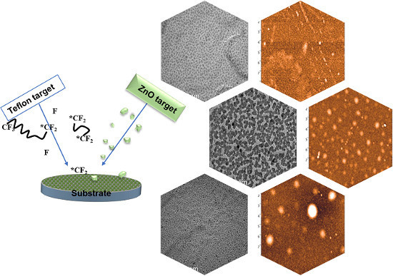
2.2. IBS Deposition of ZnO-CFx Nanocomposites

A “customized” dual-ion-beam system with ion-beam-assisted growth, already described elsewhere [3,45], was used to deposit the zinc oxide-fluoropolymer (ZnO-CFx) nanocomposites. In order to improve the ZnO’s stoichiometry, the deposition of all of the nanocomposites was assisted with a low energy ion beam fluxing O2 at 3 sccm (standard cubic centimeters per minute) in the assistance gun. Growth rates ( r ) of each component of the nanocomposite material were separately evaluated by means of a quartz microbalance sensor placed close to the substrate. The film’s thickness was 150 nm unless otherwise stated. Nanocomposites were prepared at three different ZnO volume fractions (φ = 0.05, 0.10, 0.15) [45]. Details about φ calculations are reported in Equation (S1).

2.3. Morphological Characterization of ZnO-CFx Nanocomposites

TEM microscopy was performed with an FEI (Eindhoven, The Netherlands) Tecnai T12 instrument (high tension: 120 kV; filament: LaB6) on 30-nm-thick samples deposited onto a carbon-coated Cu grid (300 mesh, Agar Scientific, Essex, UK). The microscope was calibrated by using the S106 Cross Grating (2160 lines/mm, 3.05 mm) supplied by Agar Scientific. Alignments and astigmatism correction were carried out following the factory settings and fast Fourier transform processing, respectively.
AFM micrographs were acquired on 150-nm-thick films with a Keysight AFM system Model 5500 (Keysight, Santa Rosa, CA, USA), in dynamic (“tapping”) mode, in air, using polygonal Si probes with a typical tip radius of 8 nm (Nanoworld, Neuchâtel, Switzerland) NCL-W Pointprobe®. The nominal spring constant and resonance frequency were within the range of 31–71 N/m and 160–210 kHz, respectively. To evaluate surface roughness, the root-mean-squared roughness (RMS) on a sample’s surface was determined within 10 × 10 μm2 areas for each sample, as (1):
R M S = 1 N j = 1 N r j 2
where r j is the single collected roughness data, and N is the number of experimental points. All AFM topographies were analyzed using the freely available software Gwyddion 2.41 (http://gwyddion.net/).

2.4. Surface Analytical Characterization by XPS

XPS measurements were performed using a Theta Probe Thermo (Hillsboro, OR, USA) VG Scientific spectrometer. All spectra were recorded in constant analyzer energy (CAE) mode using a pass energy of 150 eV for survey and 100 eV for high resolution regions (F1s, C1s, O1s, Zn2p and ZnL3M45M45). The calibration of the binding energy (BE) scale was performed by taking a suitable signal as internal reference. In particular, for φ = 0 and φ = 0.05, the reference peak was the -CF2 component of the C1s signal (BE = 291.8 eV) related to the polymer backbone. For φ = 0.10 and φ = 0.15, the C–C component of the C1s signal (BE = 284.8 eV) was chosen as reference because of the high extent of defluorination in the polymer matrix. Data analysis and curve-fit procedures were performed by the commercial software Thermo Avantage© (v. 5.937, 2014) from Thermo Scientific. The absence of sample degradation upon exposure to X-rays (e.g., defluorination of the organic matrix and polymer matrix crosslinking) was evaluated by cyclic acquisition of the F1s and C1s high resolution regions, and was negligible within the acquisition time of a whole spectral set. The atomic percentage surface composition was determined by considering integrated peak areas (after Shirley background removal) and Scofield sensitivity factors.

2.5. Water Contact Angle (WCA) Measurements

Dynamic WCA measurements were carried out using a Ramé-Hart (Succasunna, NY, USA) manual goniometer (model A-100). Contact angles were measured on five double-distilled water drops for each sample, and the average value was calculated. Advancing and receding contact angles were measured according to the sessile drop method. A 1-μL droplet was firstly deposited on a sample’s surface by a micrometer syringe and its volume was increased, forcing the droplet to advance onto the sample until a constant contact angle was observed. This constant contact angle represented the advancing contact angle. Then, the droplet was then progressively shrunk until a radius decrease occurred. The last contact angle value read before radius change was the receding WCA. For all contact angle data, a minimum uncertainty of ±1° was assumed.

3. Results and Discussion

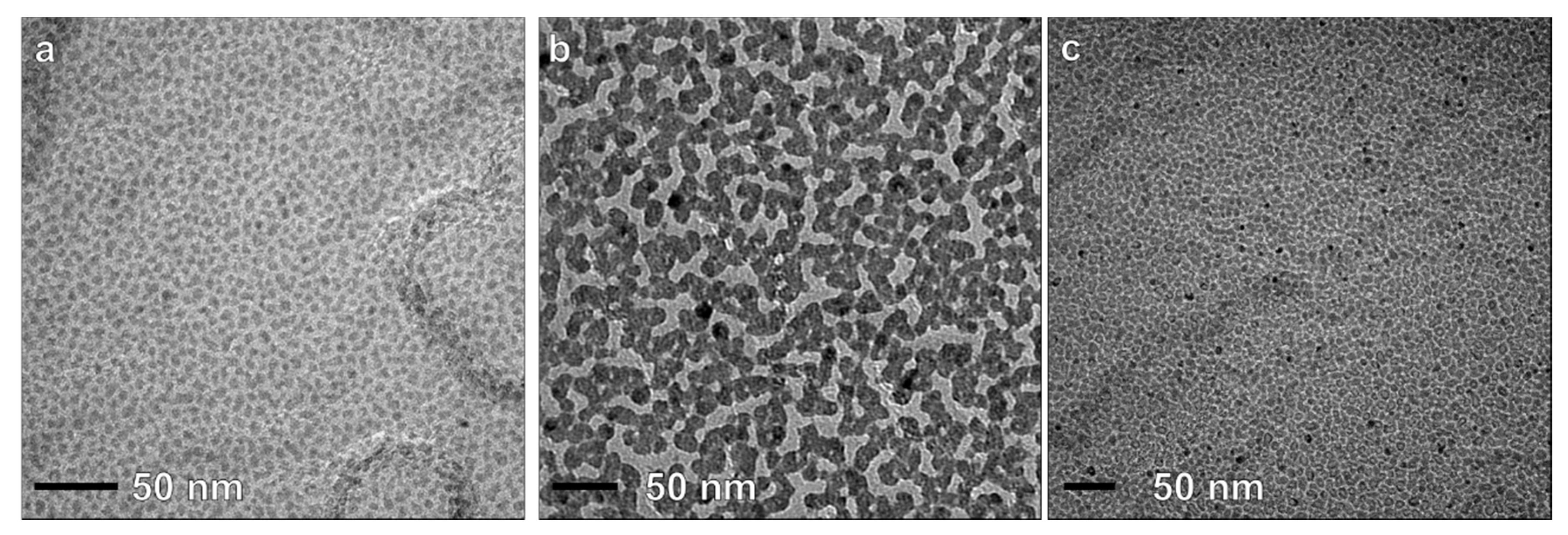
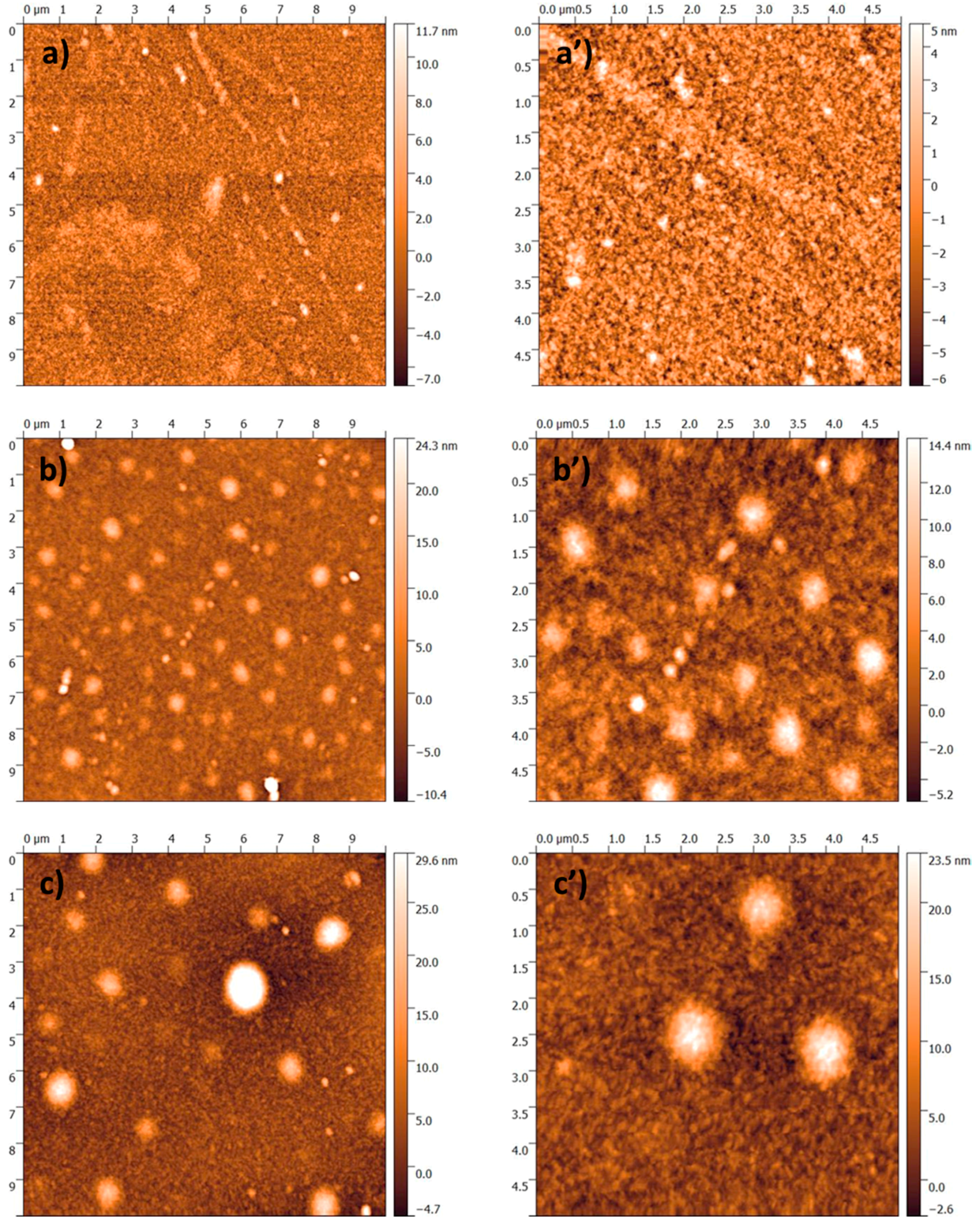
3.1. Thin Film Deposition and Morphological Characterization

Optimized IBS deposition parameters for composite ZnO-CFx thin films, at different inorganic volume fractions, have already been reported elsewhere [45]. We previously demonstrated that, with this technique, an organic-inorganic thin film with an easily tunable thickness and φ could be prepared. In this study, ZnO-CFx composites were characterized by a good morphological in-plane homogeneity, as shown in the TEM micrographs reported in Figure 1.
For the lowest inorganic volume fraction, i.e., φ = 0.05, ZnO clusters with an average cluster size of 5–8 nm were appreciable (Figure 1a). Anyhow, the ZnONP morphology showed dependence upon φ. In fact, both the cluster size and its surface density increased with the ZnO loading. In particular, for φ = 0.10 (Figure 1b) and φ = 0.15 (Figure 1c), cluster coalescence occurred with evident percolation pathways. The TEM pictures of the ZnO-CFx ultrathin films should be only considered as elucidative images, being most of the study focused on much thicker coatings, which are more representative of the material when it is used in real-life applications.
When depositing thicker films (150 nm), the ZnO-CFx composites showed the presence of large spheroidal islands/clusters (with diameters higher than 100 nm and height of tens of nm) laying down on a low-roughness background. The surface roughness (RMS) ranged from 1.31 ± 0.05 nm (for φ = 0.05) to 2.03 ± 0.09 nm (for φ = 0.15) as outlined in Figure 2.
Cluster abundance was a function of φ, while their average in-plane size appeared to be not affected by the ZnO loading. These large spheroidal features were not visible in thinner films subjected to TEM characterization. Hence, their presence could be attributed to the deposition of a thicker layer. In order to understand their physicochemical nature, the same samples underwent scanning electron microscopy (SEM) and energy dispersive X-ray (EDX) spectroscopy (for experimental details please refer to the electronic Supplementary Material). The surface morphology observed by SEM was analogous to the one revealed by AFM. For explicative purposes, SEM micrographs of ZnO-CFx thin films are reported in Figure S1. An elemental analysis was performed both on clusters and substrate, and the results obtained are reported in Table 1 as a function of φ.
The F/Zn ratio diminishes with φ, as expected. Anyhow, it is worth noting that this ratio is lower in the case of clusters with respect to the amorphous polymeric background on which the sub-micron structures lay. This was considered indicative of the chemical nature of the spheroidal features, which were mostly composed by inorganic material and covered by a polymer layer.

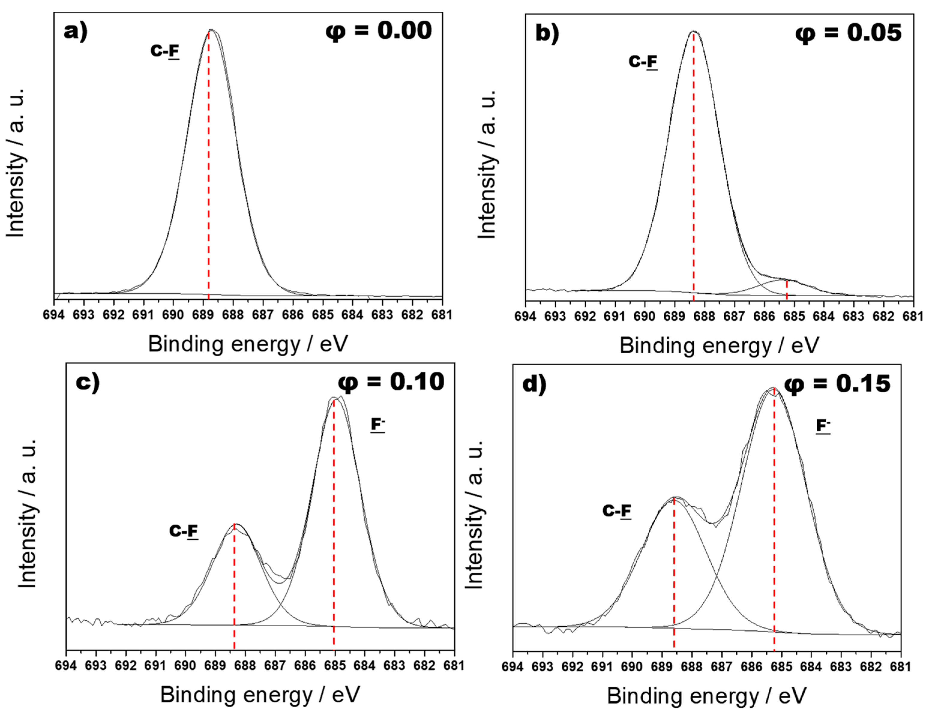
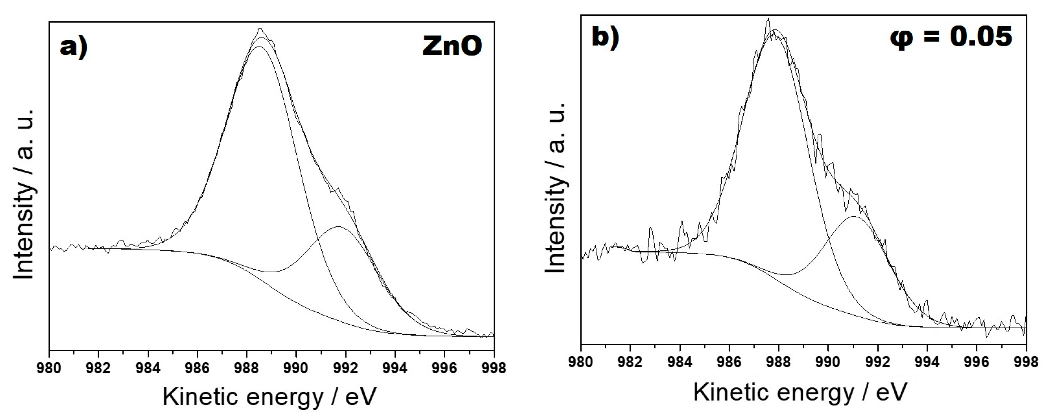
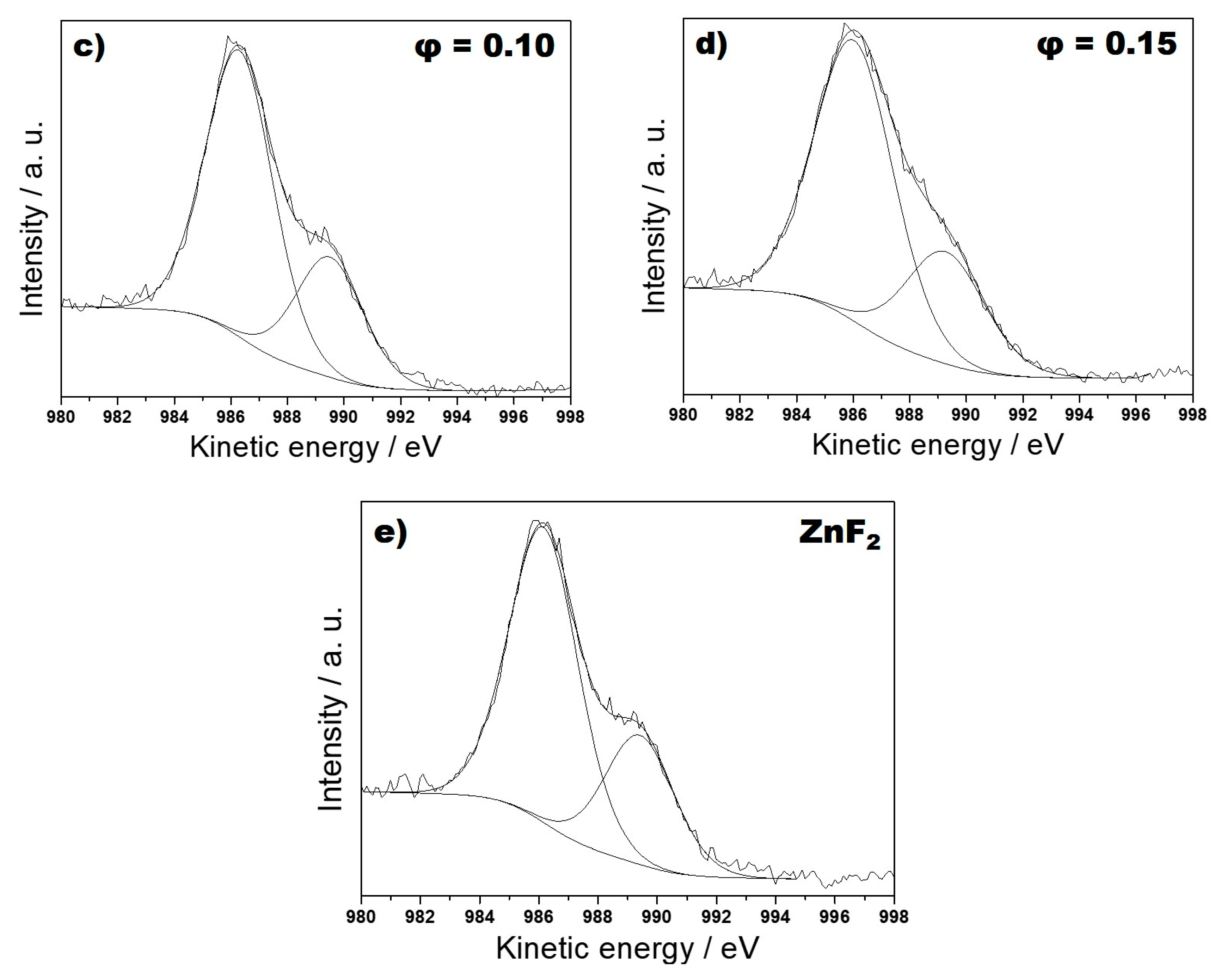
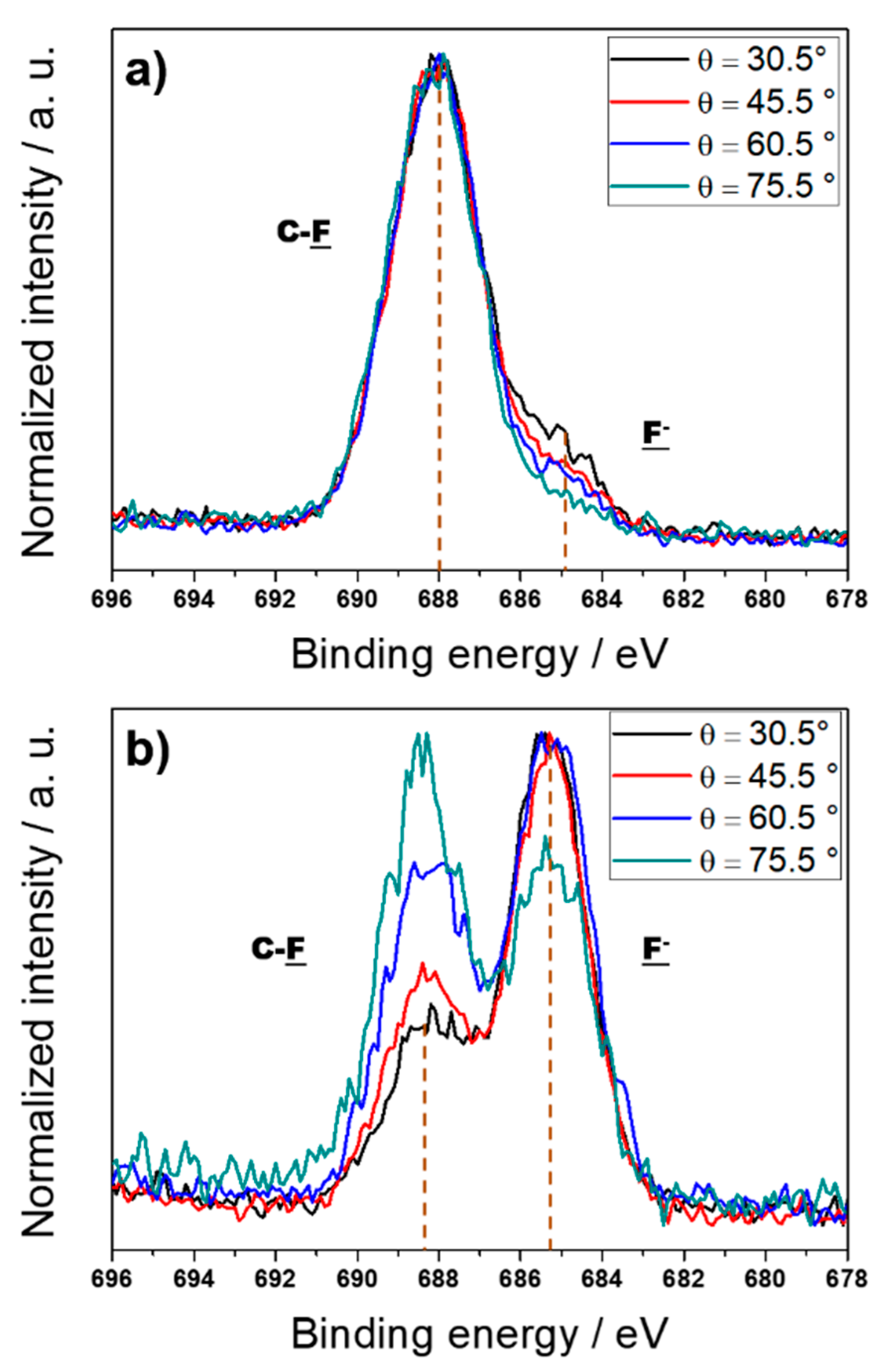
3.2. Surface Analytical Characterization

X-Ray Photoelectron Spectroscopy (XPS) was systematically employed to characterize the surface chemical composition of the nanomaterials. Elemental quantification is summarized in Table 2 as a function of φ.
On the one hand, the zinc and oxygen percentages increased with φ and remained almost constant for φ ≥ 0.10. A certain divergence with the results obtained for analogous Pd-CFx and Cu-CFx materials was noticed; in these previous studies, the surface atomic percentages of inorganic components increased systematically as a function of the metal loading [14,46]. On the other hand, the fluorine percentage followed an opposite trend, decreasing noticeably at higher inorganic loadings [13,14,45,46]. Polymer reticulation and defluorination were considered responsible for this experimental evidence. A detailed curve-fit procedure was applied to all high resolution regions for each value of φ. In the C1s region (Figure S2), six or seven photoelectron components were used to process the signal, whose position and relative abundances are listed in Table S1 and described in the corresponding text.
A general inspection of the C1s spectra (Figure S2) indicated that the fluoropolymer matrix structure changed profoundly with φ. At φ = 0.10 (Figure S2b) and φ = 0.15 (Figure S2c), a shift towards lower BE values was found in the C1s spectra, probably due to a massive polymer defluorination and reticulation. Otherwise, ZnO-CFx materials with a low zinc oxide content (i.e., φ = 0.05, Figure S2a) gave the typical C1s spectrum of a fluoropolymer [14] with a low branching degree. The F1s high resolution region (Figure 3) was curve-fitted, in all cases, with two components. The one on the right, centered at 684.8 ± 0.2 eV, was attributed to inorganic fluoride (F); this signal component grew with φ.
The other one, at 688.8 ± 0.2 eV, was attributed to organic fluorine (C-F), and its relative abundance decreased with increasing inorganic loading. Therefore, it could be inferred that the formation of inorganic fluoride was somehow related to the amount of inorganic phase in the composite thin film. Important information about zinc chemical speciation was obtained by the analysis of the Auger ZnL3M45M45 region (Figure 4). The region was curve-fitted using two signal components, with a large FWHM (full width at half maximum) of 3.5 ± 0.2 eV, and a Gaussian–Lorentzian ratio of 30.0 ± 0.5. The presence of such broad signals could be explained based on the coalescence of the fine transition structure that could be observed in the Auger spectrum of metallic zinc into two large, merged signal components [47].
Separation between the two peaks was quite constant, and approximately equal to 3.3 ± 0.1 eV. The position of the major component was used to calculate modified auger parameters (α’) in order to assess zinc chemical speciation [48]. At increasing φ values, the formation of zinc fluoride (ZnF2) could be observed. Such a phenomenon has already been proved in other composite fluoropolymeric films containing transition metal clusters [13,14,46]. This was confirmed by a shift in the modified Auger parameter from values typical for ZnO, of about 2010.6 ± 0.2 eV, to values attributable to the formation of the inorganic halide: 2008.4 ± 0.3 eV [49]. To facilitate the comparison of all spectra, the Auger signals for a pure, IBS-deposited, ZnO thin film and for a standard ZnF2 powder are reported in Figure 4. On the one hand, the presence of the halide appeared to be predominant in the samples with φ ≥0.10, so that the position of the analyzed signals did not significantly differ from that of ZnF2. On the other hand, the Auger region of the composite with φ = 0.05 was comparable to that of pure ZnO. The corresponding Zn2p regions did not show significant differences, as expected, despite the significant variation in the chemical speciation of the aforementioned element, and therefore they are not shown here.

3.3. Water Contact Angle (WCA) Measurements

Water contact angle values, acquired in dynamic mode, are reported in Table 3 as a function of φ. The advancing water contact angle is similar for all surfaces, and it is sensitive to the presence of the hydrophobic fluorinated moieties. Major differences can be observed in the receding water contact angle values, which decrease from 73 to 28 degrees. This trend can be explained considering the hydrophilicity of ZnO [50,51]. It is well-known, in fact, that a receding contact angle probes the density of high-surface energy moieties [52]. Therefore, samples with higher ZnO content show lower receding contact angles. Correspondingly, a very high hysteresis (i.e., difference between advancing and receding angles) was found for samples with a ZnO loading equal to 0.10 and 0.15. Based on the AFM results, since surface roughness is of a few nm maximum, its contribution to contact angle hysteresis can be neglected and chemical heterogeneity can be regarded as the main factor affecting dynamic sample wettability.

3.4. Treatments in Deposition Chamber to Reduce Fluorides Content

The first part of this work, which deals with the spectroscopic and morphological characterization of composite materials without post-deposition treatments, must be considered as the main focus of this paper. Despite the presence of inorganic fluorides, these materials are very useful in many other applications, ranging from catalytic de-polymerization processes [51] to the modification of paddings and mattresses not in direct contact with human skin. The aim of this paragraph is just to add a useful piece of information for those readers interested in the textile manufacturing application of composite materials, thus providing complimentary information to what we reported in [45]. As shown, samples with higher loadings had a significant atomic percentage of inorganic fluoride that was about 26% of the total fluorine. This evidence posed a significant drawback to the possibility of using these nanomaterials as antimicrobial coatings of industrial products (textiles, leather, etc.), since ZnF2 is an irritant for human skin [52]. Therefore, in order to remove inorganic fluoride from the composite films, sample treatments were here developed and optimized, either in the deposition step, or at the end of it. The presence of a metal oxide as the sputtering target leads to the preferential deposition of the metal, which has a higher vapor pressure compared to oxygen and is not lost in the gaseous form during the deposition. The presence of non-coordinated metal in the fluoropolymer matrix was held to be responsible for the extraction of fluorine from it (refer to previous paragraphs) with consequent high CFx cross-linking. Hence, the deposition of a nanocomposite film at φ = 0.15 was carried out at room temperature using a combined flow of Ar and O2 (2 sccm Ar + 0.5 sccm O2), instead of pure Ar for ZnO sputtering, during the entire IBS process. A post-deposition thermal treatment was implemented, as an alternative method, on samples at φ = 0.15. At the end of a standard deposition, we proceeded to flush 5 sccm of O2 in the IBS chamber for 10 m. After that, in the presence of the same gas, the temperature of the substrate holder was raised prior to 50 °C and then, with a step of 10 °C up to 100 °C, for 1 h. We choose not to exceed 100 °C because Teflon®’s glass-transition temperature is 120 °C [53]. To test the efficacy of these two new protocols, samples were immediately subjected to a surface chemical composition analysis by parallel angle-resolved XPS (PAR-XPS). For the experiments here discussed, spectra were collected at four detection angles, ranging between 30.5° (most bulk-sensitive angle) and 75.5° (most surface-sensitive angle), through constant steps of 15°. Surface chemical composition was determined for each value of θ, with particular attention to the F component (684.8 ± 0.2 eV) in the F1s spectra’s high resolution regions. In Figure 5, we report the trend of the signal as a function of θ for each treatment.
In the sample that underwent thermal treatments (Figure 5a), the abundance of inorganic fluoride (684.8 ± 0.2 eV) decreased with the sampling depth, and the second component (688.8 ± 0.2 eV), related to organic fluoride, grew with φ. These data were consistent with the well-known assumption that zinc-containing nanophases tend to penetrate into the “soft” Teflon®-like matrix, causing the abstraction of fluorine with the consequent formation of ZnF2 and polymer crosslinking. On the other hand, from the analysis of the sample prepared with an auxiliary O2 flow (Figure 5b), it was clear that inorganic fluorine become the minority moiety for the most superficial acquisition angles. Hence, this treatment caused an increase in the relative abundance of ZnO, and this phenomenon was more significant for the outer portions of the sample surface.

4. Conclusions

ZnO-CFx nanocomposites with different inorganic fractions were deposited by IBS by properly tuning the deposition parameters. Material characterization by TEM, AFM, and XPS showed differences to previously reported metal-CFx nanocomposites. The ZnO cluster size increased with φ, and nanoparticle aggregation was observed at high φ values. Surface XPS characterization exhibited how an extremely branched polymer dispersing matrix was produced in comparison to the homologous metal-CFx (Au-CFx, Ag-CFx, Cu-CFx) materials that were developed and characterized in the past by the same authors. The presence of significant quantities of ZnF2 on the surface of these nanocomposites was observed. Hence, sample treatments were developed in order to obtain a complete stoichiometry for the inorganic nanophases and allow for the conversion of fluorides into ZnO. This was done in order to prevent any possible harmful action of ZnF2 in all of those cases in which the coatings could be used for applications involving skin contact (such as the development of an antimicrobial textile or leather). The experimental approach based on post-deposition thermal treatments herein presented shows an interesting way to solve an important problem related to surface properties. From a diagnostic point of view, the understanding of ZnL3M45M45 Auger transitions, because of the lack of an adequate level of information present in the literature, suggested to us the need to develop curve-fit models of this region that can provide important information about chemical speciation of composites where zinc is simultaneously present in multiple chemical states. These composite materials showed great application potentiality, which could be explored in the controlled modification of industrial products, as outlined in the Supplementary Information (Figures S3 and S4). Moreover, they could be proficiently applied as depolymerization catalysts in ionic liquid media, as we have recently demonstrated for other ZnO nanoparticle-containing materials [51].

Supplementary Materials

The following are available online at https://www.mdpi.com/2076-3417/8/1/77/s1, Figure S1: 150-nm-tick ZnO-CFx composite films were morphologically characterized by SEM analysis, at 30 kV with a Hitachi SEM-FEG 5000 microscope on gold-coated sample. Figure S2: C1s XP-high resolution regions of ZnO-CFx nanocomposites having an inorganic phase volume fraction φ = 0 (a), φ = 0.05 (b), φ = 0.10 (c), and φ = 0.15 (d). Figure S3: Real textile materials modified with ZnO-fluoropolymer nanocomposites at different inorganic loading. Figure S4: Water contact angle measurement on unfinished real leather modified with ZnO-fluoropolymer nanocomposites at different inorganic loading. Measured values are: 69.5 ± 0.5° at φ = 0, 114.1 ± 0.5° at φ = 0.05, and 103.5 ± 0.5° at φ = 0.15.Table S1: Relative abundances (%) of different carbon moieties, derived from the C1s curve-fitting, as a function of φ.

Acknowledgments

Part of this work was financially supported by Italian MIUR Project No. PONa3 00369. Financial support from Regione Puglia, in the scientific Research Project “Laboratorio di tecnologie di modificazione superficiale di fibre naturali per il rilancio del settore tessile in Puglia”—Avviso pubblico n. 16/2009 POR PUGLIA 2007–2013 “Reti di Laboratori Pubblici di Ricerca,” is acknowledged for TEM facility. The Institute of Analytical and Bioanalytical Chemistry, Ulm University, is acknowledged for AFM facility.

Author Contributions

M.C.S. performed most of the characterization experiments and wrote the first draft of the paper. M.V. optimized and performed the IBS deposition experiments. R.A.P. contributed to the XPS analyses. A.M. performed the SEM-EDX and WCA measurements. A.N., A.V. and N.C. coordinated and supervised the activities. Authorship is limited to those who have contributed substantially to the work reported.

Conflicts of Interest

The authors declare no conflict of interest. The founding sponsors had no role in the design of the study; in the collection, analyses, or interpretation of data; in the writing of the manuscript, and in the decision to publish the results.

References

  1. Loh, K.J.; Chang, D. Zinc oxide nanoparticle-polymeric thin films for dynamic strain sensing. J. Mater. Sci. 2010, 46, 228–237. [Google Scholar] [CrossRef]
  2. D’Agostino, R. Plasma Deposition, Treatment, and Etching of Polymers: The Treatment and Etching of Polymers; Elsevier: Amsterdam, The Netherlands, 2012; ISBN 978-0-323-13908-3. [Google Scholar]
  3. Quaranta, F.; Valentini, A.; Favia, P.; Lamendola, R.; d’Agostino, R. Ion-beam sputtering deposition of fluoropolymer thin films. Appl. Phys. Lett. 1993, 63, 10–11. [Google Scholar] [CrossRef]
  4. Sanchez, C.; Julián, B.; Belleville, P.; Popall, M. Applications of hybrid organic–inorganic nanocomposites. J. Mater. Chem. 2005, 15, 3559–3592. [Google Scholar] [CrossRef]
  5. Uno, M.; Tominari, Y.; Takeya, J. Fabrication of high-mobility organic single-crystal field-effect transistors with amorphous fluoropolymer gate insulators. Org. Electron. 2008, 9, 753–756. [Google Scholar] [CrossRef]
  6. Wu, J.; Xia, J.; Zhang, Y.; Lei, W.; Wang, B. A simple method to fabricate the different extents of superhydrophobic surfaces. Phys. E Low-Dimens. Syst. Nanostruct. 2010, 42, 1325–1328. [Google Scholar] [CrossRef]
  7. Bayat, A.; Ebrahimi, M.; Nourmohammadi, A.; Moshfegh, A.Z. Wettability properties of PTFE/ZnO nanorods thin film exhibiting UV-resilient superhydrophobicity. Appl. Surf. Sci. 2015, 341, 92–99. [Google Scholar] [CrossRef]
  8. Mohamed, A.M.A.; Jafari, R.; Farzaneh, M. An optimization of superhydrophobic polyvinylidene fluoride/zinc oxide materials using Taguchi method. Appl. Surf. Sci. 2014, 288, 229–237. [Google Scholar] [CrossRef]
  9. Liu, Z.; Wang, H.; Wang, E.; Zhang, X.; Yuan, R.; Zhu, Y. Superhydrophobic poly(vinylidene fluoride) membranes with controllable structure and tunable wettability prepared by one-step electrospinning. Polymer 2016, 82, 105–113. [Google Scholar] [CrossRef]
  10. Bahgat, A.; Mohamed, A.M.A.; Abdullah, A.M.; Almaadeed, M. Superhydrophobic and Corrosion Behavior of Electrospun PVDF-ZnO Coating. ECS Trans. 2015, 64, 57–67. [Google Scholar] [CrossRef]
  11. Luan, B.C.D.; Huang, J.; Zhang, J. Enhanced thermal conductivity and wear resistance of polytetrafluoroethylene composites through boron nitride and zinc oxide hybrid fillers. J. Appl. Polym. Sci. 2015, 132. [Google Scholar] [CrossRef]
  12. Zha, J.W.; Dang, Z.M.; Zhao, K.; Zheng, X.Q.; Li, S.T. Prominent nonlinear electrical conduction characteristic in T-ZnOw/PTFE composites with low threshold field. IEEE Trans. Dielectr. Electr. Insul. 2012, 19, 567–573. [Google Scholar] [CrossRef]
  13. Cioffi, N.; Losito, I.; Torsi, L.; Farella, I.; Valentini, A.; Sabbatini, L.; Zambonin, P.G.; Bleve-Zacheo, T. Analysis of the Surface Chemical Composition and Morphological Structure of Vapor-Sensing Gold—Fluoropolymer Nanocomposites. Chem. Mater. 2002, 14, 804–811. [Google Scholar] [CrossRef]
  14. Cioffi, N.; Ditaranto, N.; Torsi, L.; Picca, R.A.; Sabbatini, L.; Valentini, A.; Novello, L.; Tantillo, G.; Bleve-Zacheo, T.; Zambonin, P.G. Analytical characterization of bioactive fluoropolymer ultra-thin coatings modified by copper nanoparticles. Anal. Bioanal. Chem. 2005, 381, 607–616. [Google Scholar] [CrossRef] [PubMed]
  15. Nikiforov, A.Y.; Deng, X.; Onyshchenko, I.; Vujosevic, D.; Vuksanovic, V.; Cvelbar, U.; De Geyter, N.; Morent, R.; Leys, C. Atmospheric pressure plasma deposition of antimicrobial coatings on non-woven textiles. Eur. Phys. J. Appl. Phys. 2016, 75, 24710. [Google Scholar] [CrossRef]
  16. Sportelli, M.C.; Picca, R.A.; Cioffi, N. Nano-Antimicrobials Based on Metals. In Novel Antimicrobial Agents and Strategies; Phoenix, D.A., Harris, F., Dennison, S.R., Eds.; Wiley-VCH Verlag GmbH & Co. KGaA: Weinheim, Germany, 2014; pp. 181–218. ISBN 978-3-527-67613-2. [Google Scholar]
  17. Pollini, M.; Paladini, F.; Sannino, A.; Picca, R.A.; Sportelli, M.C.; Cioffi, N.; Nitti, M.A.; Valentini, M.; Valentini, A. Nonconventional routes to silver nanoantimicrobials: Technological issues, bioactivity, and applications. In Nanotechnology in Diagnosis, Treatment and Prophylaxis of Infectious Diseases; Kon, M.R., Ed.; Academic Press: Boston, MA, USA, 2015; Chapter 6; pp. 87–105. ISBN 978-0-12-801317-5. [Google Scholar]
  18. Sportelli, M.C.; Picca, R.A.; Cioffi, N. Recent advances in the synthesis and characterization of nano-antimicrobials. TrAC Trends Anal. Chem. 2016, 84 Pt A, 131–138. [Google Scholar] [CrossRef]
  19. Zaporojtchenko, V.; Chakravadhanula, V.S.K.; Faupel, F.; Tamulevičius, S.; Andrulevičius, M.; Tamulevičienė, A.; Augulis, L. Residual stress in polytetrafluoroethylene-metal nanocomposite films prepared by magnetron sputtering. Thin Solid Films 2010, 518, 5944–5949. [Google Scholar] [CrossRef]
  20. Farella, I.; Valentini, A.; Cioffi, N.; Torsi, L. Dual ion-beam sputtering deposition of palladium-fluoropolymer nano-composites. Appl. Phys. A 2005, 80, 791–795. [Google Scholar] [CrossRef]
  21. Faupel, F.; Zaporojtchenko, V.; Greve, H.; Schürmann, U.; Chakravadhanula, V.S.K.; Hanisch, C.; Kulkarni, A.; Gerber, A.; Quandt, E.; Podschun, R. Deposition of Nanocomposites by Plasmas. Contrib. Plasma Phys. 2007, 47, 537–544. [Google Scholar] [CrossRef]
  22. Faupel, F.; Zaporojtchenko, V.; Strunskus, T.; Elbahri, M. Metal-Polymer Nanocomposites for Functional Applications. Adv. Eng. Mater. 2010, 12, 1177–1190. [Google Scholar] [CrossRef]
  23. Wang, X.; Hall, J.E.; Böhm, G.G.A.; Lin, C.J. Nano-Sized Polymer-Metal Composites. U.S. Patent 7,112,369, 26 September 2006. [Google Scholar]
  24. Michalczyk, M.J.; Sharp, K.G.; Stewart, C.W. Fluoropolymer Nanocomposites. U.S. Patent 5,726,247, 10 March 1998. [Google Scholar]
  25. Roy, R.A.; Messier, R.; Krishnaswamy, S.V. Preparation and properties of r.f.-sputtered polymer-metal thin films. Thin Solid Films 1983, 109, 27–35. [Google Scholar] [CrossRef]
  26. See, K.C.; Spicer, J.B.; Brupbacher, J.; Zhang, D.; Vargo, T.G. Modeling Interband Transitions in Silver Nanoparticle—Fluoropolymer Composites. J. Phys. Chem. B 2005, 109, 2693–2698. [Google Scholar] [CrossRef] [PubMed]
  27. Wei, H.; Eilers, H. Electrical conductivity of thin-film composites containing silver nanoparticles embedded in a dielectric fluoropolymer matrix. Thin Solid Films 2008, 517, 575–581. [Google Scholar] [CrossRef]
  28. Rahachou, A.V.; Rogachev, A.A.; Yarmolenko, M.A.; Jiang, X.-H.; Liu, Z.B. Molecular structure and optical properties of PTFE-based nanocomposite polymer–metal coatings. Appl. Surf. Sci. 2012, 258, 1976–1980. [Google Scholar] [CrossRef]
  29. Liu, C.; Fairhurst, R.; Ren, L.; Green, S.; Tong, J.; Arnell, R. Co-deposition of titanium/polytetrafluoroethylene films by unbalanced magnetron sputtering. Surf. Coat. Technol. 2002, 149, 143–150. [Google Scholar] [CrossRef]
  30. Pihosh, Y.; Biederman, H.; Slavinska, D.; Kousal, J.; Choukourov, A.; Trchova, M.; Mackova, A.; Boldyryeva, A. Composite SiOx/fluorocarbon plasma polymer films prepared by r.f. magnetron sputtering of SiO2 and PTFE. Vacuum 2006, 81, 38–44. [Google Scholar] [CrossRef]
  31. Özgür, Ü.; Alivov, Y.I.; Liu, C.; Teke, A.; Reshchikov, M.A.; Doğan, S.; Avrutin, V.; Cho, S.-J.; Morkoç, H. A comprehensive review of ZnO materials and devices. J. Appl. Phys. 2005, 98. [Google Scholar] [CrossRef]
  32. Tan, W.K.; Razak, K.A.; Ibrahim, K.; Lockman, Z. Formation of ZnO nanorod arrays on polytetraflouroethylene (PTFE) via a seeded growth low temperature hydrothermal reaction. J. Alloys Compd. 2011, 509, 820–826. [Google Scholar] [CrossRef]
  33. Srivastava, M.; Basu, B.B.J.; Rajam, K.S. Improving the Hydrophobicity of ZnO by PTFE Incorporation. J. Nanotechnol. 2011, 2011, 392754. [Google Scholar] [CrossRef]
  34. Li, F.; Hu, K.; Li, J.; Zhao, B. The friction and wear characteristics of nanometer ZnO filled polytetrafluoroethylene. Wear 2001, 249, 877–882. [Google Scholar] [CrossRef]
  35. Liu, Y.; Yuan, Y.; Li, C.; Gao, X.; Cao, X.; Li, J. The structure and photoluminescence properties of RF-sputtered films of ZnO on Teflon substrate. Mater. Lett. 2008, 62, 2907–2909. [Google Scholar] [CrossRef]
  36. Wei, Q.; Yu, L.; Hou, D.; Huang, F. Surface characterization and properties of functionalized nonwoven. J. Appl. Polym. Sci. 2008, 107, 132–137. [Google Scholar] [CrossRef]
  37. Fahlteich, J.; Steiner, C.; Schiller, N.; Miesbauer, O.; Noller, K.; Deichmann, K.-J.; Mirza, M.; Amberg-Schwab, S. Roll-to-roll thin film coating on fluoropolymer webs—Status, challenges and applications. Surf. Coat. Technol. 2017, 314, 160–168. [Google Scholar] [CrossRef]
  38. Neelakantan, N.K.; Weisensee, P.B.; Overcash, J.W.; Torrealba, E.J.; King, W.P.; Suslick, K.S. Spray-on omniphobic ZnO coatings. RSC Adv. 2015, 5, 69243–69250. [Google Scholar] [CrossRef]
  39. Liu, Y.; Zang, Y.; Wei, G.; Li, J.; Fan, X.-L.; Cheng, C. Stress and structural studies of ZnO thin films on polymer substrate under different RF powered conditions. Mater. Lett. 2009, 63, 2597–2599. [Google Scholar] [CrossRef]
  40. Guo, Q.X.; Mitsuishi, Y.; Tanaka, T.; Nishio, M.; Ogawa, H.; Huang, Y.Z. Microfabrication of ZnO on a PTFE Template Patterned by Using Synchrotron Radiation. J. Korean Phys. Soc. 2008, 53, 2796. [Google Scholar] [CrossRef]
  41. Zhang, Y.H.; Ji, Q.; Wang, X. RF Sputtering of Composite Fluorocarbon/ZnO Films and their Basic Properties. Key Eng. Mater. 2008, 373–374, 159–162. [Google Scholar] [CrossRef]
  42. Zhang, Y.H.; Ji, Q.; Liu, R.; Liu, Z.; Qi, H. Structure and washing fastness of composite fluorocarbon/ZnO films prepared by RF sputtering. Surf. Coat. Technol. 2009, 203, 3405–3409. [Google Scholar] [CrossRef]
  43. Zhang, Y.H. Composite fluorocarbon/ZnO films prepared by RF magnetron sputtering of Zn and PTFE. Surf. Coat. Technol. 2008, 202, 2612–2615. [Google Scholar] [CrossRef]
  44. Zhang, Y.H.; Ji, Q.; Liu, Z.J. Preparation and UV Absorption Property of Hybrid Fluorocarbon/ZnO Thin Films Deposited by RF Magnetron Sputtering. Adv. Mater. Res. 2010, 143, 792–796. [Google Scholar] [CrossRef]
  45. Sportelli, M.C.; Nitti, M.A.; Valentini, M.; Picca, R.A.; Bonerba, E.; Sabbatini, L.; Tantillo, G.; Cioffi, N.; Valentini, A. Ion Beam Sputtering Deposition and Characterization of ZnO-Fluoropolymer Nano-Antimicrobials. Sci. Adv. Mater. 2014, 6, 1019–1025. [Google Scholar] [CrossRef]
  46. Cioffi, N.; Farella, I.; Torsi, L.; Valentini, A.; Sabbatini, L.; Zambonin, P.G. Ion-beam sputtered palladium-fluoropolymer nano-composites as active layers for organic vapours sensors. Sens. Actuators B 2003, 93, 181–186. [Google Scholar] [CrossRef]
  47. Schön, G. Auger and direct electron spectra in X-ray photoelectron studies of zinc, zinc oxide, gallium and gallium oxide. J. Electron Spectrosc. Relat. Phenom. 1973, 2, 75–86. [Google Scholar] [CrossRef]
  48. Wagner, C.D.; Joshi, A. The auger parameter, its utility and advantages: A review. J. Electron. Spectrosc. Relat. Phenom. 1988, 47, 283–313. [Google Scholar] [CrossRef]
  49. NIST XPS Database. Available online: http://srdata.nist.gov/xps (accessed on 3 December 2017).
  50. Luckenbach, R. Beilstein Handbook of Organic Chemistry: Covering the Literature from 1960 through 1979; 5th Supplementary Series; Springer: New York, NY, USA, 1982; ISBN 978-3-540-11341-6. [Google Scholar]
  51. Palumbo, F.; Mundo, R.D. Wettability: Significance and measurement. In Polymer Surface Characterization; De Gruyter: Berlin, Germany; Boston, MA, USA, 2014; Chapter 7; ISBN 978-3-11-028811-7. [Google Scholar]
  52. Zinc Fluoride. Available online: https://toxnet.nlm.nih.gov/ (accessed on 3 December 2017).
  53. Iannone, F.; Casiello, M.; Monopoli, A.; Cotugno, P.; Sportelli, M.C.; Picca, R.A.; Cioffi, N.; Dell’Anna, M.M.; Nacci, A. Ionic liquids/ZnO nanoparticles as recyclable catalyst for polycarbonate depolymerization. J. Mol. Catal. A Chem. 2017, 426, 107–116. [Google Scholar] [CrossRef]
Figure 1. Transmission electron microscopy (TEM) micrographs of ZnO-CFx nanocomposites having an inorganic phase volume fraction of φ = 0.05 (a); φ = 0.10 (b); and φ = 0.15 (c).
Applsci 08 00077 g001
Figure 2. Atomic force microscopy (AFM) micrographs of ZnO-CFx nanocomposites having an inorganic phase volume fraction of φ = 0.05 (aa’), φ = 0.10 (bb’), and φ = 0.15 (cc’).
Applsci 08 00077 g002
Figure 3. F1s XP-high resolution regions of ZnO-CFx nanocomposites having an inorganic phase volume fraction φ = 0 (a), φ = 0.05 (b), φ = 0.10 (c), and φ = 0.15 (d).
Applsci 08 00077 g003
Figure 4. ZnL3M45M45 XP-high resolution regions of ZnO-CFx nanocomposites having an inorganic phase volume fraction of φ = 0.05 (b); φ = 0.10 (c); and φ = 0.15 (d). The same region for a pure ZnO film (a) and a ZnF2 standard (e) is also reported, for comparison.
Applsci 08 00077 g004aApplsci 08 00077 g004b
Figure 5. F1s XP-high resolution regions of ZnO-CFx nanocomposites having an inorganic phase volume fraction of φ = 0.15 as a function of θ and subject to thermal treatment in an oxygenated atmosphere (a) or deposited with an auxiliary O2 flow (b).
Applsci 08 00077 g005
Table 1. energy dispersive X-ray (EDX) elemental analysis, as a function of the metal oxide volume fraction φ. Error is 0.4% in all cases. n.d. = not detectable.
φSample Region% F% ZnF/Zn
0.05Clustern.d.n.d.-
Backgroundn.d.n.d.-
Total7.20.236.0
0.10Cluster2.00.63.3
Background3.30.84.1
Total3.40.84.2
0.15Cluster2.41.71.4
Background5.61.53.7
Total5.31.53.5
Table 2. ZnO-CFx surface elemental composition as a function of the metal oxide volume fraction φ. Errors are calculated as standard deviation on three replicates.
φ% C% F% O% Zn
0.0546.3 ± 0.33.4 ± 0.251.6 ± 0.41.4 ± 0.2
0.1033.5 ± 1.48.8 ±0.243.6 ± 0.814.2 ± 0.4
0.1535.6 ± 0.48.9 ±0.240.9 ± 0.214.1 ± 0.5
Table 3. Dynamic water contact angles as a function of φ.
φθ Advancing/Degreeθ Receding/Degree
0.05112 ± 173 ± 1
0.10108 ± 128 ± 2
0.15111 ± 128 ± 1

