Article

Femtosecond Laser Direct Write Integration of Multi-Protein Patterns and 3D Microstructures into 3D Glass Microfluidic Devices

1
RIKEN Center for Advanced Photonics, 2-1 Hirosawa, Wako, Saitama 351-0198, Japan
2
Brain Science Institute, RIKEN, 2-1 Hirosawa, Wako, Saitama 351-0198, Japan
*
Author to whom correspondence should be addressed.
Appl. Sci. 2018, 8(2), 147; https://doi.org/10.3390/app8020147
Submission received: 17 December 2017 / Revised: 18 January 2018 / Accepted: 20 January 2018 / Published: 24 January 2018

Abstract

:

Featured Application

Index matching for ship-in-a-bottle integration by glycerol-water solvents. 3D biomimetic features and binding assays in biochips.

Abstract

Microfluidic devices and biochips offer miniaturized laboratories for the separation, reaction, and analysis of biochemical materials with high sensitivity and low reagent consumption. The integration of functional or biomimetic elements further functionalizes microfluidic devices for more complex biological studies. The recently proposed ship-in-a-bottle integration based on laser direct writing allows the construction of microcomponents made of photosensitive polymer inside closed microfluidic structures. Here, we expand this technology to integrate proteinaceous two-dimensional (2D) and three-dimensional (3D) microstructures with the aid of photo-induced cross-linking into glass microchannels. The concept is demonstrated with bovine serum albumin and enhanced green fluorescent protein, each mixed with photoinitiator (Sodium 4-[2-(4-Morpholino) benzoyl-2-dimethylamino] butylbenzenesulfonate). Unlike the polymer integration, fabrication over the entire channel cross-section is challenging. Two proteins are integrated into the same channel to demonstrate multi-protein patterning. Using 50% w/w glycerol solvent instead of 100% water achieves almost the same fabrication resolution for in-channel fabrication as on-surface fabrication due to the improved refractive index matching, enabling the fabrication of 3D microstructures. A glycerol-water solvent also reduces the risk of drying samples. We believe this technology can integrate diverse proteins to contribute to the versatility of microfluidics.

Graphical Abstract

1. Introduction

Microfluidics is increasingly influential to not only academia but also industry in diverse fields including biology, chemistry, medicine, foods, energy, environment, etc. because of the advantageously small footprint sizes, high sensitivity, feature diversity, and compartmentalization [1]. In particular, the medical applications of microfluidics are rapidly growing because of two aspects. Feature diversity and compartmentalization allow the fabrication of so-called organ- or body-on-a-chip devices, which recreate organ or bodily functions mimicking appropriate bodily responses on microchips for drug screening [2]. Small footprint sizes allow efficient and complex detection in diagnostics by so-called micro total analysis systems (μ-TAS) [3]. For all of these purposes, microfluidic devices commonly created in glass or polymer are building blocks, and desired functions are integrated to further functionalize them.
Recently, our group developed the ship-in-a-bottle integration technique to integrate functional microcomponents or create biomimetic structures by constructing three-dimensional (3D) polymer micro- and nanocomponents inside closed glass microchannels [4]. In this technique, femtosecond laser direct writing is employed to polymerize microcomponents from polymer solution inside transparent microchannels, based on multi-photon absorption processes, allowing the fabrication of nearly arbitrary and well-resolved 3D structures, as explained later. For the efficient multi-photon absorption processes, ultrashort pulses shorter than several tens of a picosecond is necessary. However, picosecond laser polymerization requires more light exposure to encounter the loss of diffusing radicals between pulses [5]. Thus, femtosecond laser polymerization combines an attractive trade-off between pulse delivery and radical generation. Using this advantage of femtosecond laser polymerization, 3D micro- and nanochannel array scaffolds were recently integrated to study cancer cell migration in biomimetic structures [6]. However, glass microfluidics and the integrated polymers are inherently inert for biological cells. We envision that the 3D integration of biomaterials such as proteins will increase biochip versatility as well as biomimetic environment due to the diversity of native and synthetic proteins available in terms of function and biocompatibility.
Protein molecules in aqueous solution can be cross-linked to construct 3D proteinaceous microstructures by the exposure of a focused femtosecond laser along its trajectory in well-resolved and controlled manners [7,8,9]. Such microstructures made of protein have been applied for cell culture scaffolds [10,11], pH-actuators [9,12,13] and optical elements [13,14]. 3D microstructures made of collagen have been shown to promote cell adhesion [10,11]. pH-change has been shown to cause the expansion or shrinking of microstructures made of bovine serum albumin (BSA) and other proteins [9,12]. This pH-actuation of BSA was applied to create pH-tunable lenses [13]. Optical waveguides made of BSA are considered environmentally friendly for device disposal [14]. These recent advances hint at enhancing the versatility of microfluidics due to specific protein functions such as cell adhesion, molecule detection, and microstructures designed for pH-actuation.
Proteinaceous pad structures integrated into microfluidics were recently reported for the detection and capture of living cells [15]. Because pads were fabricated from a protein solution on a glass surface prior to aligning and bonding a polydimethylsiloxane (PDMS) channel to the glass, this fabrication method is restricted by the PDMS bonding process. The bonding process requires dry conditions and the proteinaceous components only attached to the glass substrate, so it appears to be difficult to fill an entire cross-section of a PDMS channel with them. The required accuracy of alignment and bonding strength also would restrict design choices. The ship-in-a-bottle integration technique based on laser direct writing in a solution filled in a microchannel, even with complex shapes, can alleviate these restrictions.
Here, we report multi-pattern and 3D integration of protein microstructures into Foturan
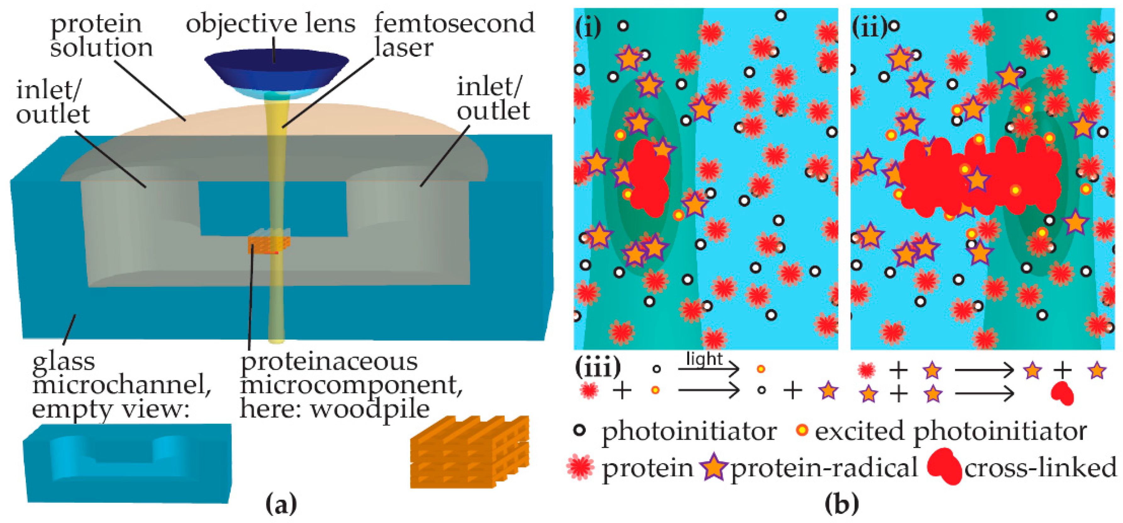
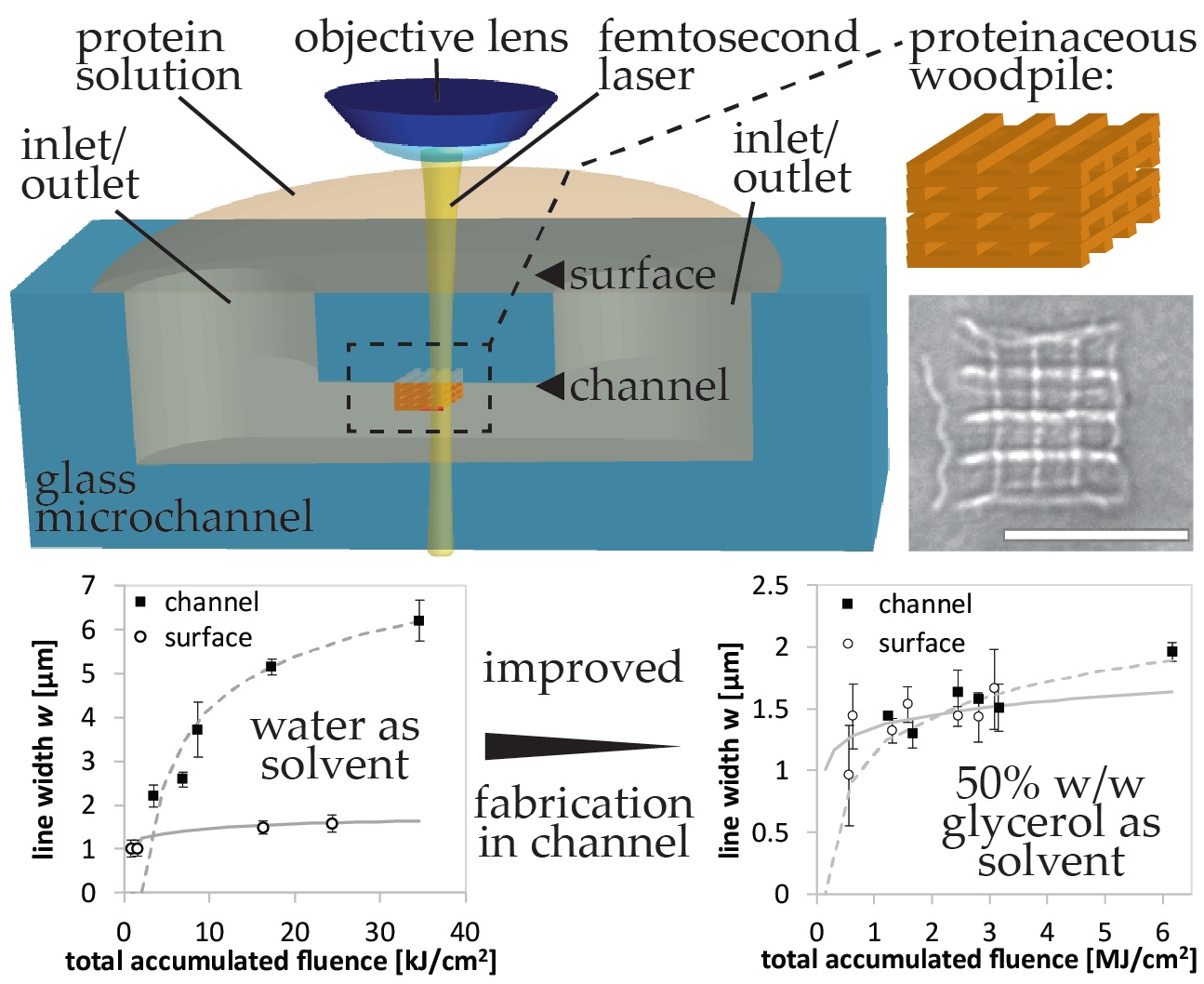
® (Schott AG, Mainz, Germany) glass microchannels by femtosecond laser direct writing-induced cross-linking. An aqueous solution of protein mixed with photoinitiator is pipetted into a glass microchannel and a femtosecond laser is focused in the sample on a personal computer (PC)-controlled stage with in situ observation using a charge-coupled device (CCD) camera (Figure 1a). The cross-linking mechanism is schematically shown in Figure 1b. When the laser irradiates the solution containing protein and photoinitiator, photoinitiator molecules are excited at the laser focus by multi-photon absorption, initiating protein molecules to become radicals. For the 3D fabrication, the multi-photon absorption processes are essential [16]. The probability of multi-photon absorption processes is strongly dependent on the laser intensity. For instance, the absorption cross-section for n-photon absorption is proportional to the n-th power of the laser intensity. Therefore, the multi-photon absorption can be efficiently induced only at a laser intensity above a specific critical value, which is dependent on both the material and the pulse width. When a femtosecond laser beam is focused inside a transparent material with an adequate pulse energy, the multi-photon absorption can be confined to a region near the focal point inside the material where the laser intensity exceeds the critical value. In this way, the internal modification of transparent materials and the fabrication of structures inside them can be performed, which enables us to create 3D structures by scanning the focused femtosecond laser beam inside the transparent materials. We generate green laser light as a second harmonic from near infrared lasers, which is transparent the glass used as microfluidic device platforms, the protein, and the photoinitiator. Subsequently, a radical chain reaction creates more radicals amongst protein molecules. While most radicals are probably relaxed due to interaction with solvent molecules, some protein radicals cross-link intermolecularly to form the proteinaceous element along the PC-controlled path of light exposure. Radicalization and subsequent cross-linking are considered to be random within a protein [11]. While femtosecond laser polymerization has a reduced risk of protein denaturation due to little heat generation, the random cross-linking might disrupt functional domains or protein tertiary structure for a subset of the protein inside the fabricated microstructure. The impact of such a disruption might depend on the structural robustness of the respective protein. Cell adhesion [10,11] and selective binding [11,12,15] have been reported to indicate that protein function was retained.
In this study, we demonstrate the integration of BSA in the glass microfluidic channels. BSA is an abundant, stable, and soluble protein from blood plasma [17], which is routinely used in 3D microfabrication [8,9,10,11,12,13,14,15]. As a photoinitiator, we utilize (Sodium 4-[2-(4-Morpholino) benzoyl-2-dimethylamino] butylbenzenesulfonate) (MBS) because it is a water-soluble variant of the widely used Irgacure 369 with a broad UV absorption peak [18,19]. MBS is free of toxic heavy metals and requires no organic solvents [20]. We further demonstrate the micropatterning of multi-proteins by a two-step integration of enhanced green fluorescent protein (EGFP) and BSA. EGFP, which is an engineered variant of GFP, is widely used for bioimaging [
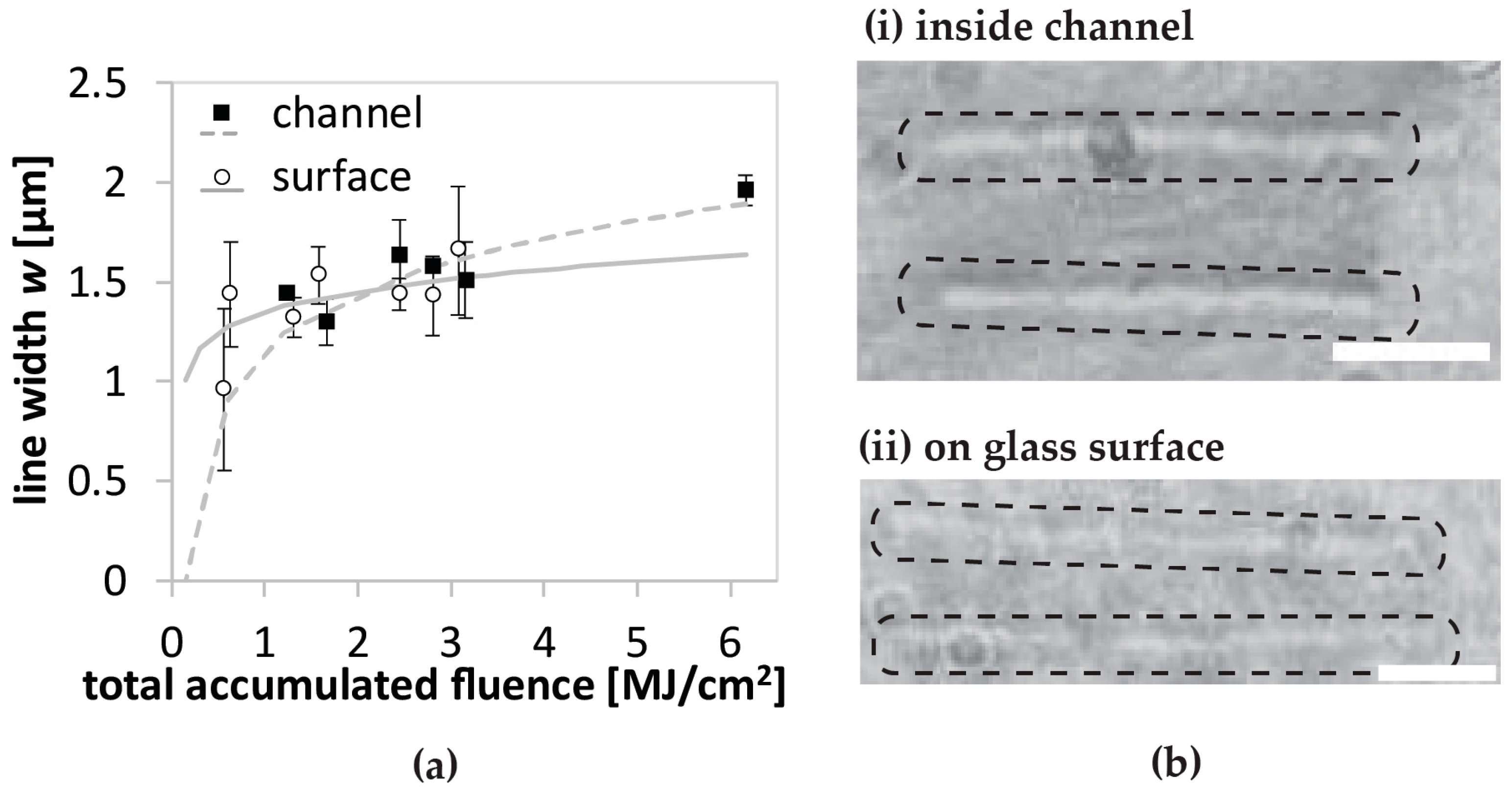
21]. However, the fabrication resolution for the in-channel integration becomes worse than that on the glass surface. By adjusting index matching between the glass and the solvent using 50% w/w glycerol solvent, we improve the fabrication resolution for the in-channel integration. Due to the improved refractive index matching, we succeed in fabricating 3D microcomponents inside a microchannel. Such integration of 3D proteinaceous microcomponents in the 3D glass microfluidic is expected to contribute to μ-TAS for detection and filtration as well as biomimetics for biochips.

2. Materials and Methods

After glycerol (G9012 Sigma-Aldrich, Tokyo, Japan) was weighed to 500 mg and deionized, purified water (Purelab, ELGA, High Wycombe, United Kingdom) was added to a total weight of 1 g to achieve a 50% w/w glycerol-water mixture. BSA powder (A7906, Sigma-Aldrich, Tokyo, Japan) was weighed and appropriately diluted with water or glycerol-water to 200 mg/mL, which equates ~3 mM. Photoinitiator MBS [18], provided by the University of Maryland, was dissolved in water at 200 mM and then mixed with BSA solution to a concentration of 100 mM MBS and 1.5 mM BSA. In order to achieve a 50% w/w glycerol-water 67 mM MBS, 1.5 mM BSA mixture, several steps were performed. First, 50 mg/mL BSA was dissolved in 75% w/w glycerol-water, then by mixing it with 200 mM MBS dissolved in water with a ratio of 2:1 we reached a 67 mM MBS 50% glycerol-water mixture of BSA. In order to accurately meet the 100 mg/mL BSA value, i.e., 1.5 mM BSA, for this mixture, a small amount of BSA was weighed and the 67 mM MBS-containing 50% glycerol-water mixture was pipetted and properly mixed. Although it might be possible to first mix MBS with glycerol-water and then add it to BSA powder of appropriate amounts, we performed several steps because pipetting glycerol at small volumes or weighing small MBS amounts were both inferior in accuracy to working with existing stock solutions prepared between 0.5 and 2 mL.
By recombinant expression, EGFP was expressed with polyhistidine tag at N terminus from E. coli JM109 (DE3) [22]. The protein was diluted with buffer solution containing 150 mM KCl and 50 mM HEPES-KOH with pH = 7.4. Concentration of EGFP was measured to be 4.7 mg/mL by a microvolume spectrophotometer BioPhotometer (Eppendorf AG, Hamburg, Germany). This solution was mixed with 20 mM MBS to obtain a final solution of 2.35 mg/mL EGFP and 10 mM MBS. In order to contrast BSA against EGFP, 20 mM of red fluorescent molecule rhodamine 6G (R6G, Junsei Chemical Co., Ltd., 87185-1610, Tokyo, Japan) was used as a photosensitizer to achieve 1 mM R6G, 200 mg/mL BSA, 50% w/w glycerol-water solution.
Glass microchannels were fabricated as described elsewhere [4,5]. In brief, focused μJ-femtosecond laser light of either fundamental wavelength at 1045 nm or second generated harmonic wavelength at 522 nm was scanned in photo-sensitive Foturan® glass to 3D space-selectively modify the glass where the cavity of the microchannel should be formed. Thereafter, glass was annealed thermally in a tubular furnace (TP20-K, Thermo RIKO Co., Ltd., Tokyo, Japan) up to 605 °C and subsequently treated with about 8% hydrofluoric acid (HF, 082-03525, Wako Pure Chemical Industries, Ltd., Osaka, Japan) for the selective wet etching of the modified regions. Lastly, surfaces of fabricated microchannels were smoothened with a second thermal annealing in the furnace up to 620 °C.
After positioning the fabricated glass microfluidics underneath the 20× objective lens (CF Plan, Nikon Corporation, Tokyo, Japan) with numerical aperture N.A. = 0.46 and a working distance of 3.1 mm, a 5–10 μL droplet of working solution was cast on the inlets. After confirming the intrusion of solution, fabrication was performed within 30 min to avoid drying and clogging of the water-dissolved samples in the microchannel. Glycerol-water-dissolved samples could be utilized within a day. We employed two femtosecond lasers in series, FCPA μJewel D-400 (IMRA America Inc., Ann Arbor, MI, USA) with 200-kHz frequency and Mikan (Amplitude Systemes, Pessac, France) with 54-MHz frequency (see Supplementary Materials for further details, Table S1) for fabrication. From the fundamental laser light, we generated a second harmonic wavelength of either 522 nm for the FCPA μJewel D-400 or about 525 nm for Mikan using a beta barium borate crystal. We observed line fabrication for n = 3–4 individual samples per fabrication scenario and measured line width for the laser powers of 0.0935–6.4 mW with scanning velocities of 0.2–10 μm/s in the case of the 200-kHz, 522-nm laser and laser powers of 3.385–6.093 mW with scanning velocities of 0.05–0.5 μm/s in the case of the 54-MHz, 525-nm laser (see Supplementary Materials for further details, Table S2). Depending on the precision of the alignment of the incidental angle to the crystal for second harmonic generation, the exact maximum laser power available could vary day by day. When fabricating with high values of fluence, the minimum velocity was limited to 0.05 μm/s of the mechanical stage. Exploring fabrication with lower values of fluence, scanning velocities outside the abovementioned ranges did not yield line fabrication.
After fabrication, samples were submerged in water to properly rinse the microchannels. For subsequent second protein fabrication, the microchannels were gently dried in air and refilled with another working solution. For the conservation of 3D microcomponents, the glass microfluidics integrated with proteins were transferred to ethanol (special grade, 057-00456, Wako Pure Chemical Industries, Ltd., Osaka, Japan) and isopropanol (166-04836, Wako Pure Chemical Industries, Ltd., Osaka, Japan) baths, respectively, and then dried in a freeze dryer (FDS-1000, Eyela, TOKYO RIKAKIKAI CO., LTD., Tokyo, Japan). Fabricated structures were observed by optical microscope Olympus BX51 (Olympus, Tokyo, Japan) and 3D optical profiler Zeta-20 (Zeta Instruments, San Jose, CA, USA). For scanning electron microscope (SEM) observation by Jeol6330 (Jeol Ltd., Tokyo, Japan), samples were metal-coated with a palladium-platinum target (MSP-20-UM, Vacuum Device, Mito, Japan). The 1-mm-thick samples were mechanically cut at the position of the inlets perpendicularly to the microchannel direction so as not to induce damage to the protein structures formed on the about 100-μm-thin microchannel glass ceiling, which allows cuts to reveal the cross-sectional view. Thereafter, samples were metal-coated again normal to the cutting cross-section to be able to image the cross-sectional view of the microchannel from the cut section.
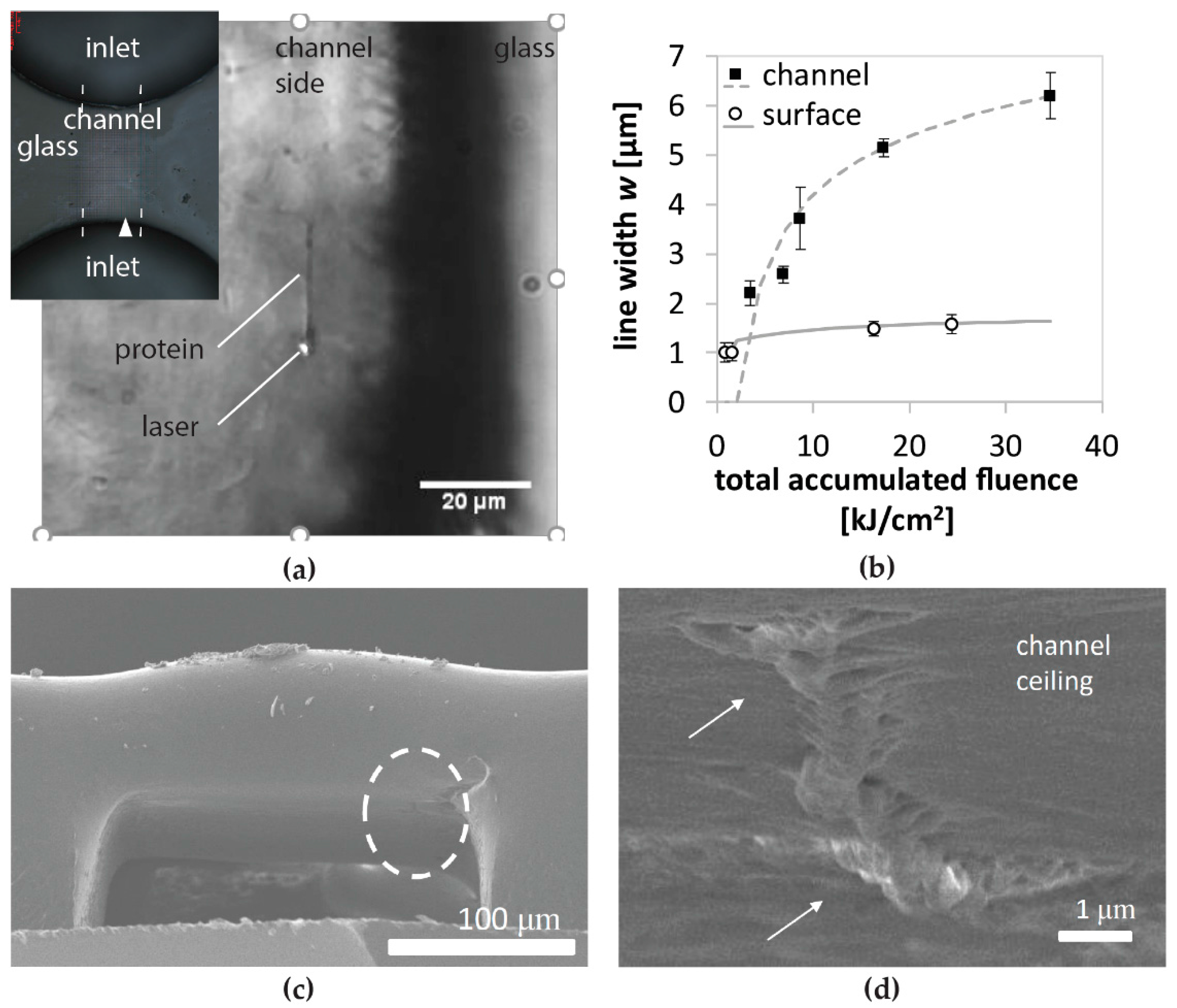
We evaluated structures and line patterns made on top of the channel surface as well as inside the channel at the ceiling. As a feature size, line width is measured from in situ images and fit against the product of the total accumulated fluence (TAF) and fluence, calculated from laser power, scanning velocity, and laser parameters. The function for fitting reflects a two-photon absorption that induces the radical generation. The dependency of the product of TAF and fluence is determined in the supplementary information using Equations (1)–(14), where the effective number of pulses [23] and line width dependence of laser power and processing time [24] are considered. The fitting results are shown in Figure S1. Since a product of TAF and fluence is not intuitive and only utilized to satisfy the equation, the fitting parameters are applied together with fluence to depict the dependency of TAF in the results.

3. Results

At first, we studied feature sizes of line patterns of BSA, and then demonstrate multi-protein integration in glass microfluidic channels. There are mainly two reasons why we started from this study. Firstly, since 3D fabrication in a channel is challenging, the fabrication conditions should be optimized using a simple scheme. Secondly, the fabrication resolution in the channel should be determined, since it could be worse than that on the surface due to spherical aberration related to laser propagation in the three different refractive index media (air, glass, and protein solution) as well as the roughness introduced by channel fabrication and local irregularities caused by heat treatment. Then, we showed our results of glycerol-water solvent improving the fabrication resolution inside microchannels, followed by the integration of true 3D microcomponents.

3.1. BSA Patterning and Feature Size Characterization

As mentioned in the introduction, BSA is widely used because of its abundance and stability [17], and it has already been reported for applications such as pH-actuation [9,12,13] and waveguides [13,14]. Studying the integration of BSA is therefore an appropriate step for utilizing it for such applications within microfluidics.
First, we examined the width of line pattern, denoted w, as a feature size in microchannels and on glass surfaces fabricated with 100 mg/mL BSA and 100 mM MBS in water. Figure 2a shows a BSA line fabricated with a 200-kHz laser of 522-nm wavelength at a laser power of 0.79 mW and scanning speed of 5 μm/s in the microchannel. The line width of pattern formed along the path of the focused laser beam was in situ observed using a CCD camera (see Supplementary Material for Video S1). The fabrication at the ceiling of the microchannel was successfully demonstrated, while fabrication at the bottom was not achieved with a water-dissolved protein solution. Furthermore, the location of successful fabrication at the ceiling also could be limited by a curved surface, as shown in Figure 2, where the central area of the channel ceiling is heavily curved. The dependence of feature sizes on total accumulated fluence is shown with fitting based on a two-photon polymerization scheme (Figure 2b), (see Supplementary Material for Equations (1)–(14) and Figure S1). Total accumulated fluence is calculated as the product of the fluence per pulse and the effective number of laser pulses. We observed an approximately 3-fold increase of line width for in-channel fabrication as compared with on-surface fabrication. By cutting the microchannel, we confirmed that the BSA line pattern was indeed located at the ceiling of the microchannel (Figure 2c,d).

3.2. Multi-Protein Integration of GFP with BSA

Integration of different kinds of proteins in a single chip in close proximity can further enhance the functionality and ability of μ-TAS or biomimetic biochips. To demonstrate the feasibility, we first filled a microchannel with 2.35 mg/mL EGFP solution with 10 mM MBS to pattern a line (Figure 3a,b). We chose EGFP because it can be easily identified by its fluorescence emission (inset in Figure 3b). After rinsing with water until the background fluorescence became stable, excess liquid was removed gently without drying the sample and then 200 mg/mL BSA with 1 mM R6G solution was added from one inlet. R6G is also a reliable photoinitiator which enabled us to demonstrate the work-flow for protein integration without drying between each step. Consequently, a BSA line pattern was successfully fabricated in proximity to the EGFP line (Figure 3c). One issue of this system is that background fluorescence, resulting from EGFP and R6G molecules non-specifically adhered to surfaces, was so strong even after washing the created structures that the BSA line could not be identified by a fluorescence measurement.

3.3. Glycerol Solvent for Improved Index Matching

Next, we studied protein polymerization using glycerol-water solvent motivated by three aspects. (i) Since a pure water solution often showed the formation of cavitation bubbles [25] when using our 200-kHz fiber laser, we intended to reduce the water fraction. (ii) In previous works, the best resolution with a submicron feature size was achieved when combining 40–50% dimethylsulfoxide (DMSO) solvents with fabrication using a high numerical aperture objective lens [8,26]. However, a high concentration of DMSO can denature the protein native structure, while glycerol is utilized for protein stabilization [27]. (iii) Increasing the refractive index from pure water n = 1.333 to over n = 1.398 [28] and even considerably higher due to the mixture of protein which possesses a high refractive index, e.g., serum albumin n = 1.590 to 1.571 [29], would enable us to match n = 1.51 of glass quite closely. An improved index matching would reduce both the spherical aberration and the light scattering at the glass channel surface due to surface roughness and local irregularities, resulting in decreased feature sizes.
Figure 4 compares the feature sizes for fabrication on the surface and inside microchannels for 50% w/w glycerol-water BSA MBS solutions. For the investigated fabrication range in the total accumulated fluence, widths of line patterns evaluated by in situ observation look comparable. Additionally, glycerol-water solutions enable the fabrication of BSA patterns on the bottom of the microchannel, probably due to the suppression of cavitation bubbles during the fabrication.

3.4. Integration of 3D BSA Microcomponent

Taking advantage of 50% w/w glycerol-water solutions containing BSA and MBS, the fabrication ability at the bottom of the microchannel is feasible to create a microstructure spanning the microchannel and thereby to integrate 3D microcomponents into the glass microfluidic device. In preliminary trials, we succeeded in spanning a 3D network over a 20-μm-high microchannel as well as integrating a four-layered 3D structure on the ceiling of a channel by using the 200-kHz, 522-nm fiber-laser. Switching lasers to the 54-MHz oscillator laser, we were able to fabricate a four-layer woodpile structure at the ceiling of a deep microchannel (Figure 5).
Figure 5a illustrates a 6-μm-high, four-layer woodpile design that has been employed for fabrication inside a microchannel as shown by the in situ time-lapse snapshots in Figure 5b. SEM observation after freeze-drying, metal coating, and glass cutting verified the formation of the structure at the channel ceiling (Figure 5c,d). The line pattern of one layer can be identified at all sides of the structure. Lines in the center are difficult to identify individually because the created structure collapsed and stacked together during the drying process. Figure 5e–g illustrates how a more compact woodpile design allowed for less collapse after drying. During cutting, the channel ceiling with the structure attached broke apart. The conservation step of drying proteinaceous microstructures is already challenging for fabrication on top of the cover glass due to the attachment and low mechanical strength; moreover, drying inside the microchannel requires refined handling. Opening the microchannel for SEM observation is also difficult, because the structures need to be close to the cross-sectional cut without breaking apart.

4. Discussion

For water solutions containing protein and photoinitiator, we attributed the cross-linking to two-photon polymerization when using femtosecond lasers with wavelengths of 522 nm and 525 nm due to the very small absorption (see 
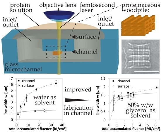
Supplementary Materials, Figure S2 and Table S3). Curve fitting using a simple logarithmic equation based on two-photon polymerization sufficiently fitted the experimental data for both in-channel and on-surface fabrication. It is noteworthy that this curve fitting equation was sufficient for both polymerization processes despite the differences in surface properties and light propagation. We showed that the total accumulated fluence was the physically relevant parameter to determine the feature size.
Feature sizes become broader for in-channel fabrication. The broader feature sizes are most likely caused by a combination of the following three aspects. The first one is spherical aberration related to laser propagation in the three different refractive index media. Specifically, the laser beam must traverse through air, glass, and protein solution for in-channel fabrication, which significantly decreases the fabrication resolution. The second is scattering due to the roughness of glass surfaces induced by microchannel fabrication. The last is the refraction of the laser beam by the curved surface, probably produced by the second heat treatment for surface smoothing, as seen in Figure 2c. Another issue of employing a pure water solution was the formation of cavitation bubbles, which inhibited us from fabricating the protein structure at the bottom of a microchannel. These facts motivated us to change the solvent to glycerol-water solvents, as further discussed later.
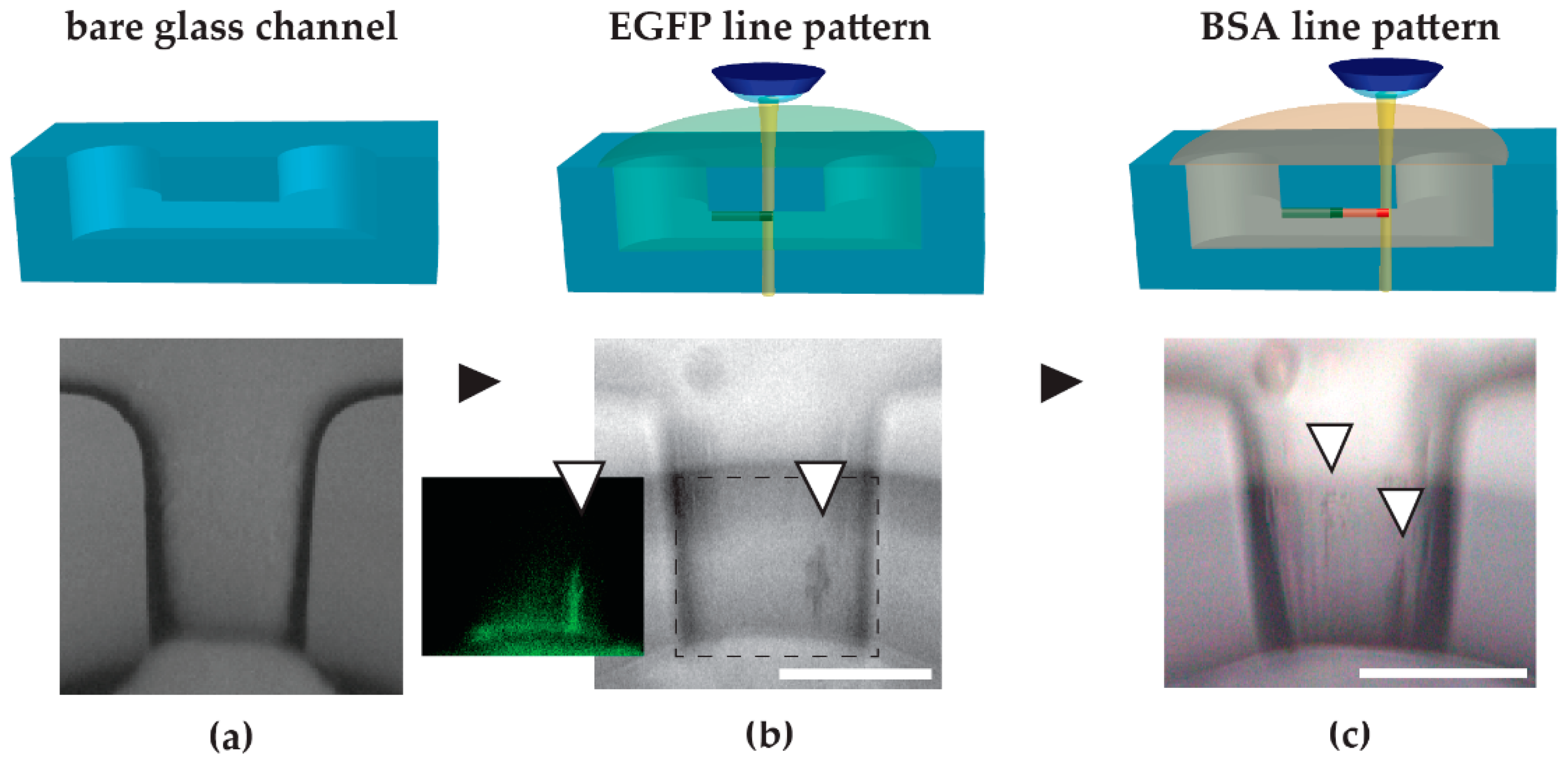
The multi-protein integration concept was demonstrated by the two-step integration of EGFP and BSA line patterns. In our experiments, we struggled with background signals originating from EGFP and R6G that non-specifically adhered to the roughened surfaces. Neutralizing the microchannel surfaces before fabrication by incubation with BSA or milk buffer for non-specific surface coating could eliminate the adsorption of those molecules to reduce the background noise. In particular, the roughened areas of the microchannel seemed to adsorb more protein molecules, creating strong background signals. One could also consider coating the channel with a thin layer of inert polymer such as parylene.
We introduced glycerol-water solvents due to three motivations: (i) the reduction of water fraction to eliminate the generation of cavitation bubbles, (ii) the replacement of DMSO in fabrication for better fabrication resolution, and (iii) the improvement of the refractive index matching. From our results, it seems that we achieved improvements of the three points in combination. One should note that although glycerol itself is viscous, glycerol-water mixtures can increase fluidity due to the polarity of water molecules [28]. Higher viscosity would be advantageous for well-connected fabrication, while higher fluidity is advantageous for microfluidic flow.
From the marginal difference in feature size for the fabrication on the surface and inside the microchannels when using the glycerol-water solvents, we can deduce that refractive index matching has abolished most of the factors increasing the feature size discussed before, i.e., aberration, scattering, and refraction. We expect the refractive index to vary with protein concentration as well as glycerol concentration. We envision that one could adjust the glycerol concentration to meet the refractive index matching for any protein concentration.
Further, we assume that glycerol hardly contributes to the cross-linking process. It could be locally radicalized at the hydroxyl residues in a manner comparable to the local radicalization of water molecules when the photoinitiator or radicalized protein interacts with solvent molecules. To clarify the details of the interaction is beyond our current knowledge, but we propose the contribution of glycerol to be similar to that of water molecules.
In situ images of line patterns are comparable for most conditions in the investigated fabrication range (Figure 4b). The use of a 20× objective lens makes it difficult to observe fine differences to fit the simulation to the two-photon absorption model. To elucidate whether there are finer differences as well as to improve the two-photon fit, extensive SEM observation seems reasonable. The difficulty of such an analysis is data acquisition against the cumulative effects of detachment due to irregularities in glass surfaces, the loss of samples when cutting samples, and the limited vision range of SEM via a tilted view of the entrance area of the microchannel.
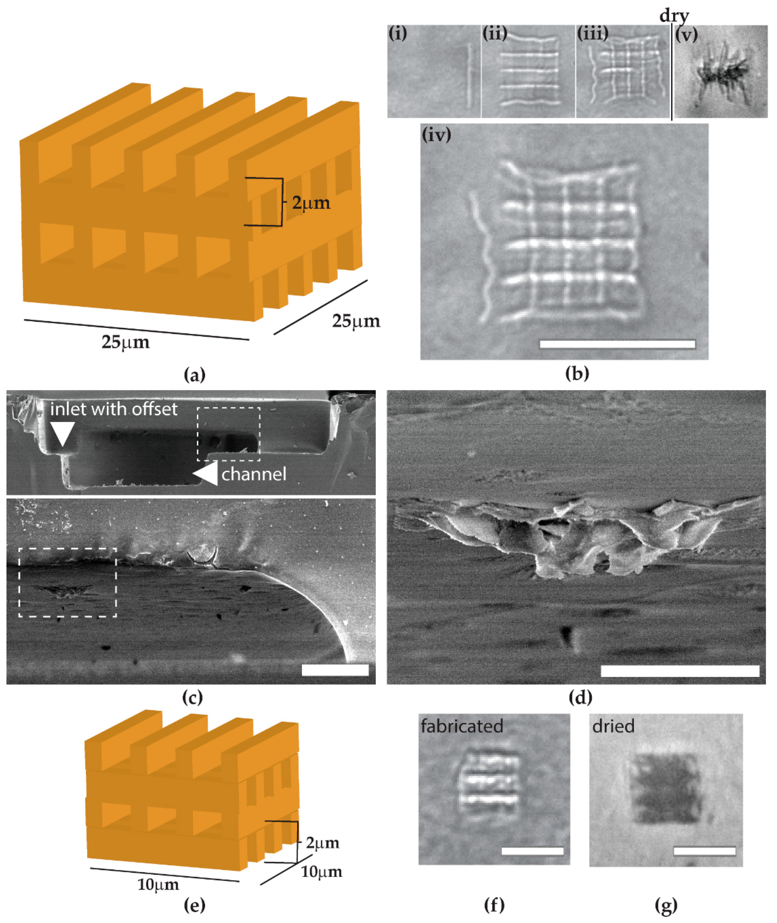
The use of glycerol-water solvent allows for true 3D microcomponent integration, which realizes the fabrication of a proteinaceous structure spanning the entire cross-section of the microchannel. The limits of channel height as well as depth from the glass surface to be integrated should be further explored. Despite freeze-dry conservation, the structure of Figure 5 collapsed partially from its original woodpile structure. This result was expected to a certain extent, because proteinaceous structures show about 20% volume loss when freeze-dried [8]. Additionally, we observed from Figure 5b that some lines were not well-connected. This could be improved by using a solution with a higher viscosity than the current one. Generally, the challenge for avoiding the collapse of structures could be addressed by improving the mechanical strength in cross-linking, e.g., by increasing the concentration of protein or photoinitiator to enhance cross-linking. One could also consider the compactness of the design, as shown in Figure 5, or a multi-component fabrication with a photoresist or polymer framework [11]. The most important factor for microfluidic application is the ability to fill or span an entire cross-section of a channel with 3D architectures, but the drying process might tear the created structures, particularly at the center area of the channel. For cross-section spanning applications such as cell culture obstacles or filtering gate structures, it might be reasonable to continuously fabricate and utilize the device in a liquid environment without any drying processes. If the applications permit, the integration of hygroscopic molecules such as sucrose could be enough to prevent drying-induced collapse or damage.

5. Conclusions

In this paper, we studied the ship-in-a-bottle integration of proteinaceous microcomponents from a mixture of protein and photoinitiator molecules diluted in water or glycerol-water solutions. We discussed the differences in feature sizes between in-channel and on-surface fabrication. A demonstration of multi-protein integration hinted at the versatile potential for the microfluidic applications that can be reached by exchanging fabrication solutions in the microfluidic fabrication setup. We improved the fabrication resolution and quality by replacing the 100% water solution with glycerol-water solutions for refractive index matching. This replacement also enabled us to demonstrate the 3D microcomponent integration. Additionally, we discussed how to advance the technique further. Ultimately, the integration of components made from proteins, a versatile and diverse biomolecule group, has great potential to advance medical and analytical microfluidic devices.

Supplementary Materials

The following are available online at https://www.mdpi.com/2076-3417/8/2/147/s1, Table S1: Laser properties of both femtosecond lasers used in this study, Table S2: All used fabrication parameter pairs of laser power and scanning velocity, Table S3: Estimate of penetration depths, Figure S1: Actual fitting results obtained as described, Figure S2: Absorption spectra of (a) BSA in water and (b) BSA with MBS in water, Video S1: in situ 5 um-per-sec BSA MBS line pattern.

Acknowledgments

We would like to thank Materials Characterization Support Unit, RIKEN CEMS for providing access to an SEM. We gratefully acknowledge John T. Fourkas at The University of Maryland for providing the photoinitiator 4-[2-(4-morpholino)benzoyl-2-dimethylamino] butylbenzenesulfonate (MBS). We would like to thank Felix Sima, who kindly taught how to fabricate glass microchannels in Foturan®. We also thank Masahiko Hirano and Asako Tosaki, who provided plasmid DNA of EGFP and gave kind advice on purifying the solution of EGFP.

Author Contributions

Daniela Serien and Koji Sugioka conceived and designed the experiments; Daniela Serien performed the experiments and analyzed the data; Hiroyuki Kawano contributed to experiments using EGFP; Daniela Serien and Koji Sugioka wrote the paper. Hiroyuki Kawano, Atsushi Miyawaki, Katsumi Midorikawa, and Koji Sugioka guided and constructively discussed the experiments.

Conflicts of Interest

The authors declare no conflict of interest.

References

  1. Sackmann, E.K.; Fulton, A.L.; Beebe, D.J. The present and future role of microfluidics in biomedical research. Nature 2014, 507, 181–189. [Google Scholar] [CrossRef] [PubMed]
  2. Huh, D.; Torisawa, Y.; Hamilton, G.A.; Kim, H.J.; Ingber, D.E. Microengineered physiological biomimicry: Organs-on-Chips. Lab Chip 2012, 12, 2156–2164. [Google Scholar] [CrossRef] [PubMed]
  3. Fan, X.; White, I.M. Optofluidic microsystems for chemical and biological analysis. Nat. Photonic 2011, 5, 591–597. [Google Scholar] [CrossRef] [PubMed]
  4. Wu, D.; Wu, S.-Z.; Xu, J.; Niu, L.-G.; Midorikawa, K.; Sugioka, K. Hybrid femtosecond laser microfabrication to achieve true 3D glass/polymer composite biochips with multiscale features and high performance: The concept of ship-in-a-bottle biochip. Laser Photonics Rev. 2014, 8, 458–467. [Google Scholar] [CrossRef]
  5. Stankevičius, E.; Daugnoraitė, E.; Selskis, A.; Juodkazis, S.; Račiukaitis, G. Photo-polymerization differences by using nanosecond and picosecond laser pulses. Opt. Express 2017, 25, 4819–4830. [Google Scholar] [CrossRef] [PubMed]
  6. Sima, F.; Serien, D.; Wu, D.; Xu, J.; Kawano, H.; Midorikawa, K.; Sugioka, K. Micro and nano-biomimetic structures for cell migration study fabricated by hybrid subtractive and additive 3D femtosecond laser processing. In Proceedings of the SPIE International Society for Optics and Photonics on Laser-based Micro- and Nanoprocessing XI, San Francisco, CA, USA, 17 February 2017; Volume 10092. [Google Scholar] [CrossRef]
  7. Spikes, J.D.; Shen, H.-R.; Kopeckova, P.; Kopeček, J. Photodynamic crosslinking of proteins. III. Kinetics of the FMN- and rose Bengalsensitized photooxidation and intermolecular crosslinking of model tyrosine-containing N-(2-hydroxypropyl)methacrylamide Co-polymers. Photochem. Photobiol. 1999, 70, 130–137. [Google Scholar] [CrossRef] [PubMed]
  8. Serien, D.; Takeuchi, S. Fabrication of submicron proteinaceous structures by direct laser writing. Appl. Phys. Lett. 2015, 107, 013702. [Google Scholar] [CrossRef]
  9. Lee, M.R.; Phang, I.Y.; Cui, Y.; Lee, Y.H.; Ling, X.Y. Shape-shifting 3D protein microstructures with programmable directionality via quantitative nanoscale stiffness modulation. Small 2015, 11, 740–748. [Google Scholar] [CrossRef] [PubMed]
  10. Iosin, M.; Stephan, O.; Astilean, S.; Duperray, A.; Baldeck, P.L. Microstructuration of protein matrices by laser-induced photochemistry. J. Optoelectron. Adv. Mater. 2007, 9, 716–720. [Google Scholar]
  11. Serien, D.; Takeuchi, S. Multi-Component Microscaffold with 3D Spatially Defined Proteinaceous Environment. ACS Biomater. Sci. Eng. 2017, 3, 487–494. [Google Scholar] [CrossRef]
  12. Kaehr, B.; Shear, J.B. Multiphoton fabrication of chemically responsive protein hydrogels for microactuation. Proc. Natl. Acad. Sci. USA 2008, 105, 8850–8854. [Google Scholar] [CrossRef] [PubMed]
  13. Sun, Y.-L.; Dong, W.-F.; Yang, R.-Z.; Meng, X.; Zhang, L.; Chen, Q.-D.; Sun, H.-B. Dynamically Tunable Protein Microlenses. Angew. Chem. Int. Ed. 2012, 51, 1558–1562. [Google Scholar] [CrossRef] [PubMed]
  14. Sun, S.-M.; Sun, Y.-L.; Zheng, B.-Y.; Wang, P.; Hou, Z.-S.; Dong, W.-F.; Zhang, L.; Chen, Q.-D.; Tong, L.-M.; Sun, H.-B. Protein-based Y-junction optical micro-splitters with environment-stimulus-actuated adjustments. Sens. Actuator B Chem. 2016, 232, 571–576. [Google Scholar] [CrossRef]
  15. Lin, C.-L.; Pan, M.-J.; Chen, H.-W.; Lin, C.-K.; Lin, C.-F.; Baldeck, P.L. Laser cross-linking protein captures for living cells on a biochip. In Proceedings of the SPIE International Society for Optics and Photonics on Frontiers in Biological Detection: From Nanosensors to Systems VII, San Francisco, CA, USA, 7 February 2015; Volume 9310. [Google Scholar] [CrossRef]
  16. Sugioka, K.; Cheng, Y. Femtosecond laser three-dimensional micro-and nanofabrication. Appl. Phys. Rev. 2014, 1, 041303. [Google Scholar] [CrossRef]
  17. Peters, T. Serum albumin. Adv. Clin. Chem. 1970, 13, 37–111. [Google Scholar] [CrossRef] [PubMed]
  18. Kojima, K.; Ito, M.; Morishita, H.; Hayashi, N. A novel water-soluble photoinitiator for the acrylic photopolymerization type resist system. Chem. Mater. 1998, 10, 3429–3433. [Google Scholar] [CrossRef]
  19. Dawood, F.; Qin, S.; Li, L.; Lina, E.Y.; Fourkas, J.T. Simultaneous microscale optical manipulation, fabrication and immobilisation in aqueous media. Chem. Sci. 2012, 3, 2449–2456. [Google Scholar] [CrossRef]
  20. Kojima, K.; Itoh, M.; Morishita, H.; Hayashi, N. Characterization of Water-Soluble Acrylic Resist Using a Novel Photoinitiator. J. Photopolym. Sci. Technol. 1998, 11, 165–170. [Google Scholar] [CrossRef]
  21. Wiedenmann, J.; Oswald, F.; Nienhaus, G.U. Fluorescent proteins for live cell imaging: Opportunities, limitations, and challenges. IUBMB Life 2009, 61, 1029–1042. [Google Scholar] [CrossRef] [PubMed]
  22. Rosano, G.L.; Ceccarelli, E.A. Recombinant protein expression in Escherichia coli: Advances and challenges. Front. Microbiol. 2014, 5, 172. [Google Scholar] [CrossRef] [PubMed]
  23. Tan, B.; Venkatakrishnan, K.; Makaronets, A. Effects of pulsewidth on two-photon polymerization. Des. Monomers Polym. 2013, 16, 145–150. [Google Scholar] [CrossRef]
  24. Serbin, J.; Egbert, A.; Ostendorf, A.; Chichkov, B.N.; Houbertz, R.; Domann, G.; Schulz, J.; Cronauer, C.; Fröhlich, L.; Popall March, M. Femtosecond laser-induced two-photon polymerization of inorganic-organic hybrid materials for applications in photonics. Opt. Lett. 2003, 28, 301–303. [Google Scholar] [CrossRef] [PubMed]
  25. Gogate, P.R.; Kabadi, A.M. A review of applications of cavitation in biochemical engineering/ biotechnology. Biochem. Eng. J. 2009, 44, 60–72. [Google Scholar] [CrossRef]
  26. Spivey, E.C.; Ritschdorff, E.T.; Connell, J.L.; McLennon, C.A.; Schmidt, C.E.; Shear, J.B. Multiphoton Lithography of Unconstrained Three-Dimensional Protein Microstructures. Adv. Funct. Mater. 2013, 23, 333–339. [Google Scholar] [CrossRef]
  27. Vincent Vagenende, V.; Yap, M.G.S.; Trout, B.L. Mechanisms of Protein Stabilization and Prevention of Protein Aggregation by Glycerol. Biochemistry 2009, 48, 11084–11096. [Google Scholar] [CrossRef] [PubMed]
  28. Glycerine Producers’ Association. Physical Properties of Glycerine and Its Solutions, 1st ed.; Glycerine Producers’ Association: New York, NY, USA, 1963; p. 13. [Google Scholar]
  29. Hand, D.B. The refractivity of protein solution. J. Biol. Chem. 1935, 108, 703–707. [Google Scholar]
Figure 1. Schematic illustration of concept of proteinaceous microcomponent integration inside a closed microfluidic channel. (a) Illustration shows a three-dimensional (3D) glass microchannel with inlet and outlet, covered and filled with a drop of protein solution. A femtosecond laser is focused into the solution in the channel by an objective lens. Inside the channel, along the relative movement of the laser focus, protein is cross-linked to form a 3D proteinaceous microcomponent. As demonstration, we fabricate woodpile structures; line arrays that rotate by 90° every consecutive layer. The objective lens is simultaneously used for in situ observation with a charged couple device (CCD) camera. (b) Illustration of protein cross-linking initiated by the two-photon excitation of a photoinitiator along the relative laser movement from (i) to (ii). (iii) Excited photoinitiator induces the radicalization of the protein and the generated protein radicals cause further radicalization, some of which eventually cross-link with proximate other protein radicals to growingly form the 3D proteinaceous component.
Applsci 08 00147 g001
Figure 2. Bovine serum albumin (BSA) line pattern inside glass microchannel. (a) In situ CCD camera image of a BSA line pattern written with 0.79 mW and 5 μm/s by a 200 kHz, 522 nm laser focused inside the glass channel. Inset shows an optical microscope image of the top view of the glass channel with two inlets, with an arrow indicating the position of the fabricated line and view direction in SEM observation. (b) Line width w vs. total accumulated fluence for line pattern on the glass surface as well as the inside of the glass channels. Solid and dashed lines indicate fitting based on a two-photon polymerization scheme with mean square deviations R2 = 0.972 (surface) and R2 = 0.987 (channel), respectively. These line widths were observed for laser powers of 0.0935–6.4 mW with scanning velocities of 0.2–10 μm/s (n = 3 for on-surface, n = 3 for in-channel fabrication). (c) SEM image in a tilted view inside the microchannel after cutting through the inlet. The point of view is indicated in (a), and a dashed ellipse highlights the area of magnification in (d). (d) SEM image inside the microchannel of the BSA line pattern, highlighted by arrows.
Applsci 08 00147 g002
Figure 3. Multi-protein line pattern of enhanced green fluorescent protein (EGFP) and consecutive BSA inside a glass microchannel with a 200-kHz laser. Schematic drawing and top view bright field microscopy image. Black arrows indicate work-flow, white arrows highlight pattern. (a) A bare glass microchannel. (b) As a first step, the channel was filled with EGFP solution and a line was polymerized near the inlet with 6.4 mW and 2 μm/s. The dashed area was imaged by a fluorescence microscopic unit with an excitation of 450–480 nm and emission of 520–800 nm. The inset fluorescence image confirmed the EGFP line to be fluorescent. (c) In continuation, the sample was filled with BSA solution and a second line pattern was polymerized with 6.4 mW and 200 nm/s. Scale bars represent 100 μm.
Applsci 08 00147 g003
Figure 4. Writing of BSA line pattern inside a glass microchannel when using 50% w/w glycerol as a solvent and a 54-MHz, 525-nm femtosecond laser. (a) Line width w vs. total accumulated fluence for line patterns on top of the glass surface and inside the glass channel. Solid and dashed lines indicate fitting based on a two-photon polymerization scheme with R2 = 0.524 (surface) and R2 = 0.741 (channel), respectively. These line widths were observed for laser powers of 3.385–6.093 mW with scanning velocities of 0.05–0.5 μm/s (n = 4 for on-surface, n = 3 for in-channel fabrication). (b) In situ CCD camera images were modified for better visibility. Line patterns are outlined by dashed ellipses. (i) Inside, the channel lines written at 6.1 mW and 200 nm/s (upper) and 4.7 mW and 100 nm/s (lower) are shown. (ii) On the surface, two lines written at 6.1 mW and 500 nm/s are shown. Scale bars represent 10 μm.
Applsci 08 00147 g004
Figure 5. 3D BSA woodpile structures inside glass microchannels fabricated with a 54-MHz, 525-nm laser. (a) Illustration of a four-layer woodpile structure with a 2-μm layer pitch and a 25-μm side length. (b) In situ CCD camera observation of the fabrication process with 6.1 mW and 100 nm/s from (i) one line to (ii) second layer, (iii) last layer, (iv) final microcomponent, and (v) after drying. During the drying process, the free-hanging layers were drawn closely together, causing a collapse of the expected structure. (c) SEM images of the view into the microchannel. The inlet, here fabricated with an offset, and channel are indicated by arrows. The position of the woodpile is highlighted by a dashed-line rectangle. Further tilting was obstructed by the inlet. (d) SEM view, tilted 5°, of a woodpile structure attached inside the microchannel. (eg) Fabrication of a 10-μm woodpile: (e) schematic drawing, (f) final in situ observation, (g) observation after drying. The structure was lost for SEM observation when cutting the channel. Scale bars represent (b,c) 25 μm and (dg) 10 μm.
Applsci 08 00147 g005

