Effect of Meniscus Damping Ratio on Drop-on-Demand Electrohydrodynamic Jetting
by
 , and
, and
Samuel Haedong Kim
1, 
Heuiseok Kang
2,
Kyungtae Kang
2,
Sang Ho Lee
2,
Kwan Hyun Cho
2 and
Jun Young Hwang
2,* 1
Woodruff School of Mechanical Engineering, Georgia Institute of Technology, Atlanta, GA 30332, USA
2
Korea Institute of Industrial Technology, Cheonan 31056, Korea
*
Author to whom correspondence should be addressed.
Appl. Sci. 2018, 8(2), 164; https://doi.org/10.3390/app8020164
Submission received: 15 December 2017
/
Revised: 17 January 2018
/
Accepted: 23 January 2018
/
Published: 24 January 2018
(This article belongs to the Special Issue Printed Electronics 2017)
Abstract
:Drop-on-demand (DOD) electrohydrodynamic (EHD) jet printing uses a nozzle and pulsated electric fields to eject small ink droplets of functional material to the appointed spot of a substrate at the appointed time, which offers solutions of high resolution patterning for fabrication of printed electronics, bioengineering, and display. Because the EHD jet connects fine drops to yield a fine pattern, it is essential to realize high throughput by generating drops quickly and reliably. In this study, the characteristics of jetting frequency were experimentally investigated as a function of nozzle dimensions by measuring response of jetting frequency to pulsating frequency which is varying from 1 Hz to 2000 Hz. The results showed that, even when the nozzle diameter is the same, the other dimensions of the nozzle significantly change the response of jetting to high pulsating frequency. Using a linear damping model describing hydrodynamic motion of ink inside the nozzle, the different behavior of the jetting frequency was explained via the different damping ratio of the oscillating ink: contrary to an underdamped system, an overdamped system supports a jetting frequency higher than the natural frequency.
1. Introduction
Direct printing of functional electronic materials has attracted considerable interest. This method combines simple additive processing with low-cost materials and have a potential to drastically lower the cost of electronics fabrication, especially compared to that for conventional silicon processing [1]. Inkjet printing, which represents a highly established direct printing method, has been demonstrated to be capable of printing all materials required for electronics, display, optics, bioengineering, and other areas. However, there is a critical challenge of inkjet printing in that practically feasible resolution is as low as 20–30 μm. On the other hand, electro-hydro-dynamic jet (EHD-jet) printing provides high-resolution patterning (<10 μm), which means that this process has potential for application in nano-systems such as NEMS and biotechnology [2]. EHD-jet printing is a technique that uses electric fields between the nozzle and an opposing conducting substrate to make the functional electronic material flow from a nozzle via electro-hydro-dynamics. There have been studies to understand the fundamental mechanism of EHD-jet printing; however, the physics of EHD-jet printing and the parameters that affect the printing are not yet clearly understood, and these parameters will be significant for high resolution, uniform, and reproducible printing.
Meniscus deformation was investigated by changing the imposed voltage such that when the bias voltage increases, not only the meniscus height increases, but also the chance of jetting of smaller drops with lower pulse voltage also increases [3,4,5]. By changing the applied voltage and flow rate, jet type was also studied such that, as the flow rate and voltage increase, the jet-mode changes from dripping, to pulsating, to cone-jet, to tilted-jet, and to multi-jet [6,7]. Also, a number of studies investigated the effects of amplitude and frequency of electric voltage pulse on the jetting and printing characteristics for drop-on-demand (DOD) printing systems with various inks and nozzles [8,9,10,11,12,13,14]. In those previous studies, examined jetting frequency was relatively low (typically less than 100 Hz) because an EHD system has little means to stabilize the motion of the meniscus right after the detachment of the drop. This is because filling the nozzle with ink takes some time to form a stabilized drop for repeatable jetting. Understanding the movements of ink inside the nozzle is, therefore, crucial to achieve high speed jetting with small drops in advanced manufacturing.
Stachewiez et al. [15] proposed a useful model to describe the electro-hydro-dynamic movements of ink in the nozzle as an oscillatory system to explain the jetting stability with the electric pulse frequency, which introduces the natural frequency and damping ratio of the system as a function of ink property and nozzle geometry. They clearly showed that, in their underdamped jetting system with 50 μm diameter nozzle, the maximum jetting frequency is limited by the natural frequency. Interestingly, if the nozzle diameter decreases sufficiently, the damping ratio can increase to make this an overdamped system. Compared with the underdamped system, the overdamped system might be stable at the higher jetting frequency. However, direct evidence for the higher stability of the overdamped system has not been given yet.
Considering this background, for EHD jetting of Ag nanoparticle ink, this study investigates the effect of the damping ratio on the stability against pulsating frequency. EHD nozzles having various damping ratios were tested by adopting different nozzle geometries; the relation between jetting frequency and pulsating frequency was measured. The results for the overdamped system were compared with those for the underdamped system. The effect of pulsating amplitude on jetting stability was also investigated for both overdamped and underdamped systems.
2. Experimental Setup
Figure 1a is a schematic of the experimental setup for the EHD printing system. In this study, we used silver ink (DGP 40LT-15C), which contains 30~35% silver particles dissolved in Triethylene Glycol Monoethyl Ether (TGME), from ANP Co., Ltd. (Sejong, Korea) Specific resistivity of the ink is 11~12 μΩ-cm, such that the ink can easily be used to produce electronics. Density, surface tension, and viscosity of ink are 1450 kg/m3, 35 mN/m, and 15 mPa-s, respectively. Three glass nozzles having different dimensions were tested, as shown in Table 1.
Bias voltage is applied to the nozzle by a high voltage DC power supply (ConverTech, Gyeonggi, Korea, SHV 300R). To minimize the droplet size and facilitate generation of drops with low pulse voltage, bias voltage was applied at 90% of onset voltage, Von, at which point EHD-jet starts to form, as shown in Figure 1b [4,5]. The following equation estimates the value of Von [16,17]
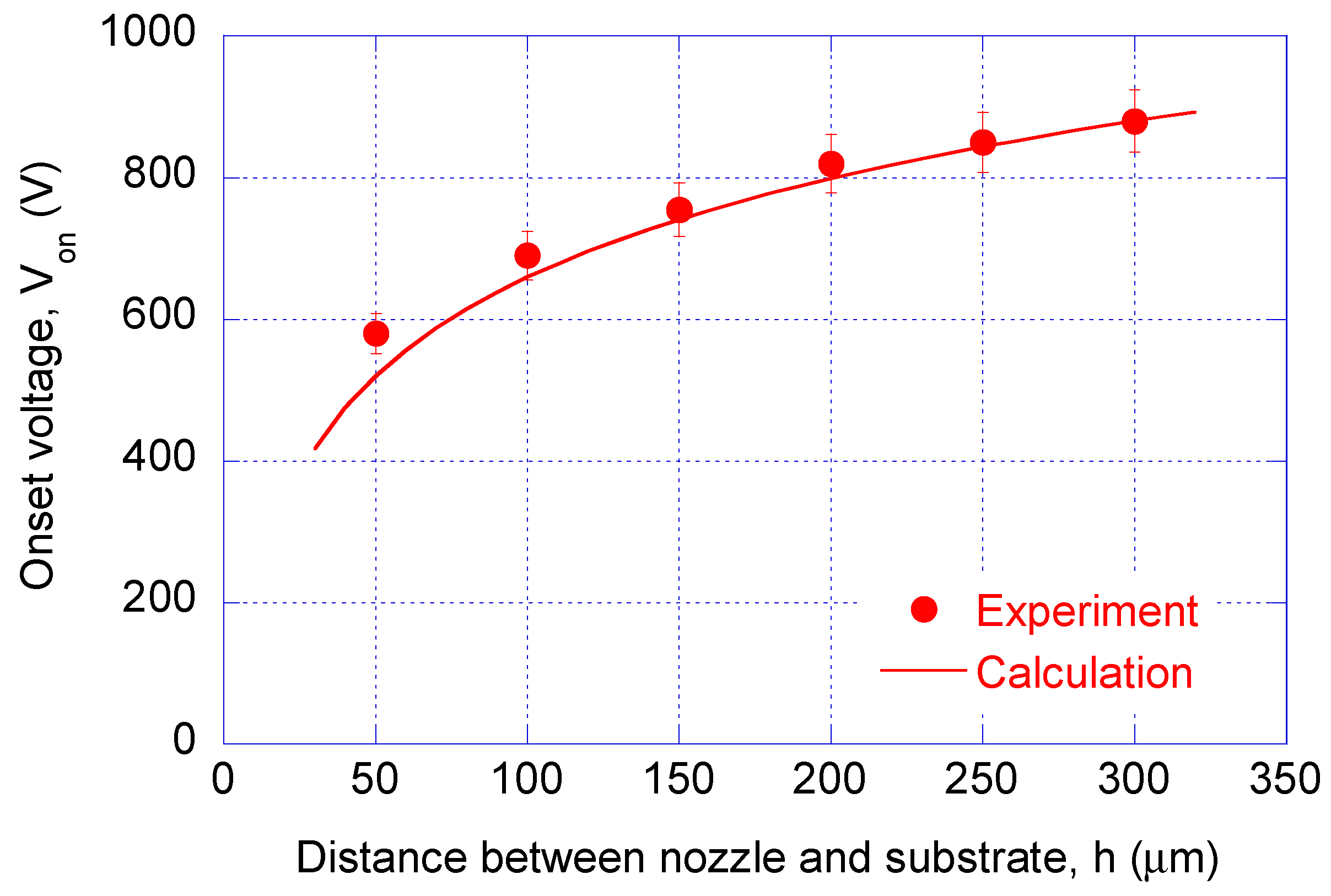
where dn is the inner diameter of the nozzle, h is the distance between the nozzle and the substrate, and γ is the surface tension of the ink; according to the Young–Laplace equation, capillary pressure in a tube is 4γ/dn, ΔP is the hydrostatic pressure, and ε is the permittivity of air, which was assumed to be 8.859 × 10⁻¹² F/m at room temperature [18]. The value of Von calculated using Equation (1) is compared with the experimental results using nozzle A, as shown in Figure 2; the results agree to each other.
A complex-waveform driver (MicroFab INC., Plano, TX, USA, JetDrive III) is used to generate a rectangular step-function signal, which is sent to the power amplifier (TREK INC., Lockport, NY, USA, TREK 2220) for 200 V/V amplification to make the voltage pulse, Vp having a duration of 500 μs, as shown in Figure 1b. In this experiment, pulsation frequency was varied from 1 to 2000 Hz while moving speed of the stage was set to the pulsation frequency multiplied by 40 μm. Therefore, the ratio of the pulsation frequency to the jetting frequency of the ink could be obtained by measuring the printed drop spacing divided by 40 μm.
3. Linear Damping Approximation
The electrohydrodynamic movements of the ink in the capillary can be described by the equation of linear damping system [19]
where m is the mass, c is the damping coefficient, k is the spring constant, and x is the ink displacement inside the capillary nozzle. The components of Equation (2), the natural oscillation frequency fc, and the damping ratio Γ, of the EHD-jet system were modeled by the following equations [19]
where H is the approximate ink column height, υ is the viscosity of the ink, l is the total length of the thinnest part, hm is the approximate meniscus height, which is approximated by 20% of the inner diameter of nozzle [15], b is the radius of the capillary far above the nozzle, as illustrated in Figure 3. All values are shown in Table 1. Table 2 shows the calculated natural frequency and the damping ratios of the four different nozzles. Regarding the dimensions of the nozzle and the property of the ink, the damping ratios of nozzle A and C are higher than 1, and that of nozzle B is smaller than 1; these values correspond to overdamped and underdamped systems, respectively.
4. Results and Discussion
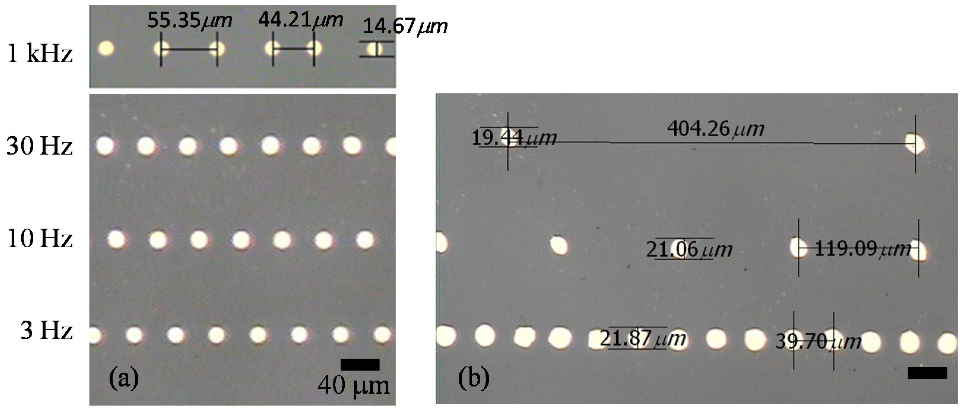
Figure 4 compares the patterns of printed drops with various pulsation frequencies for nozzle A and nozzle B at the minimum pulse voltage of jetting. The two nozzles have the same diameter dn of 30 μm and the same natural frequency fc of 224 Hz, while they have different damping ratios, as shown in Table 1 and Table 2. For nozzle A, shown in Figure 4a, where the estimated damping ratio is 2.0 (overdamped), ink drops are printed at the designed drop spacing of 40 μm for 3, 10, 30 Hz, and even for 1 kHz. The pulsed voltage in Figure 4a was 150 V. On the other hand, for nozzle B, shown in Figure 4b, where the damping ratio is 0.78 (underdamped) and the pulsed voltage is 300 V, the drop spacing becomes multiples of 40 μm as pulsation frequency increases.
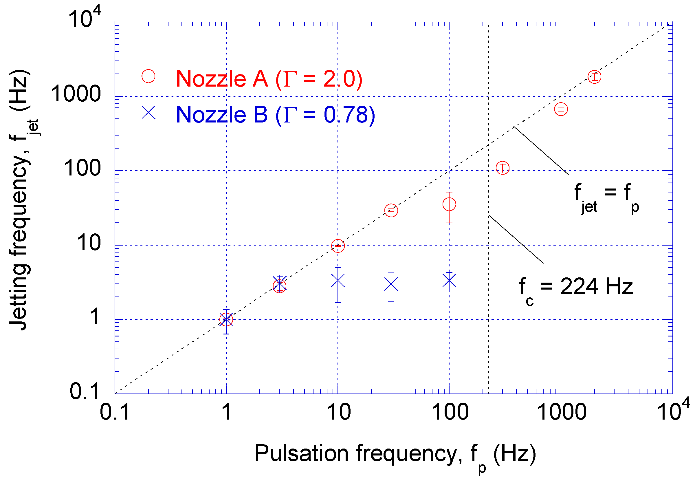
Figure 5 shows the measured jetting frequency as a function of pulsation frequency. When the system is overdamped (Γ > 1), as shown for nozzle A in Figure 5, jetting frequency is in good agreement with pulsating frequency because the ink refill time is sufficiently small [15] and the meniscus stabilizes quickly after jetting. However, when system is underdamped (Γ < 1), as shown for nozzle B in Figure 5, jetting frequency does not increase with pulsation frequency but is limited to a few Hz. This is possibly due to the capillary oscillation of the ink inside the nozzle after jetting. This result demonstrates that the overdamped EHD system is advantageous for high frequency DOD jetting. In an overdamped system, the meniscus shape and capillary force gradually change to have periodic equilibrium for a given pulsation wave. However, in an underdamped system with high frequency, there occurs instability due to an interference of capillary and pulsating waves because the capillary force varies sinusoidally in between the pulsations.
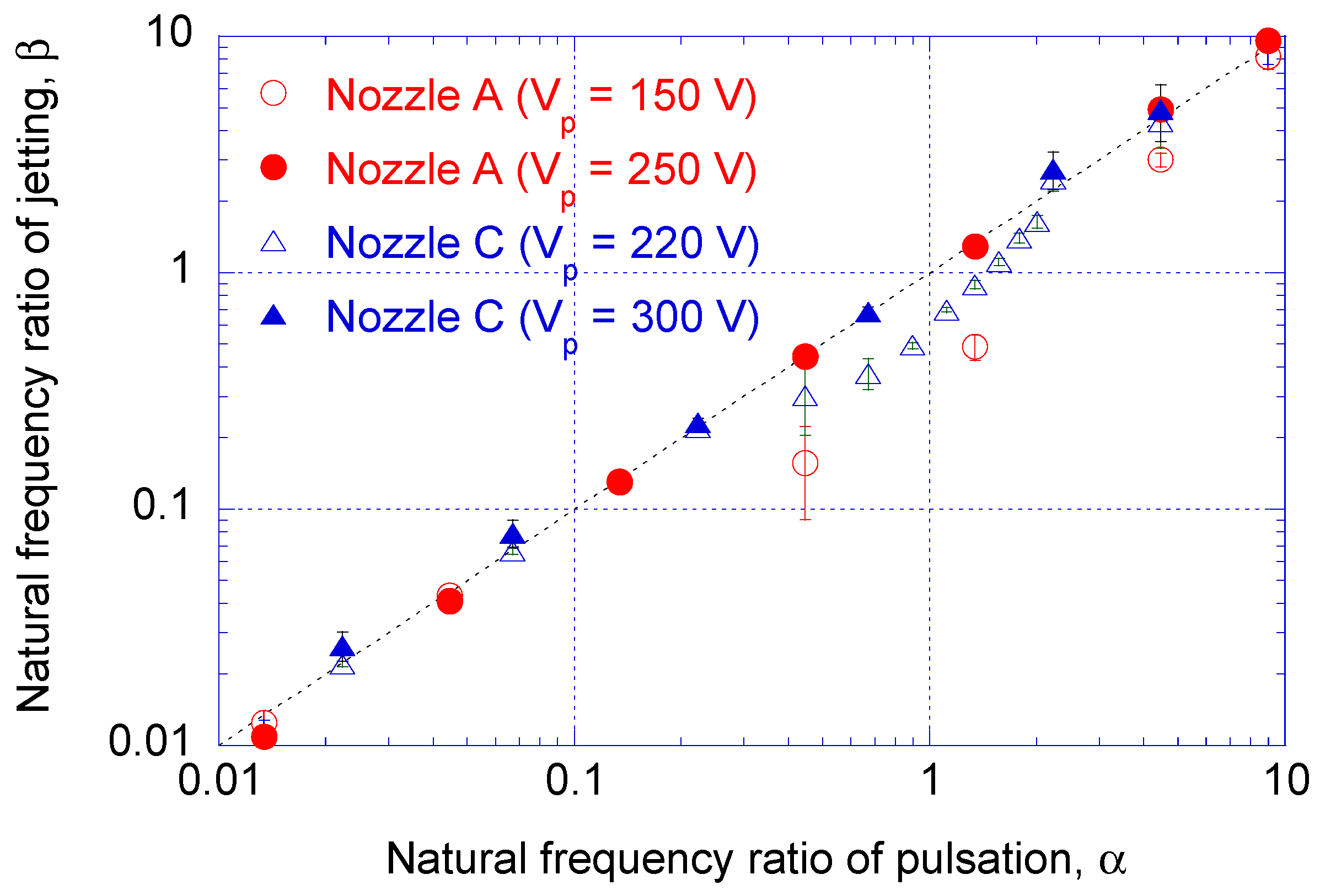
Interestingly, Figure 5 also shows that, even for the overdamped nozzle A, jetting frequency deviates from the pulsation frequency near the estimated natural oscillation frequency, fc. In order to investigate the effect of fc on DOD jetting, Figure 6 shows the jetting frequency as a function of the natural frequency ratio for overdamped nozzles A and C. As shown in Table 1 and Table 2, the inner diameter of nozzle C is 15 μm (one half the diameter of nozzle A) and, therefore, the estimated natural frequency is 448 Hz (double the natural frequency of nozzle A). The natural frequency ratios of pulsation α and jetting β are the frequencies normalized by the natural frequency, respectively.
In Figure 6, pulsed voltages Vp of either 150 V for nozzle A or 220 V for nozzle C are close to the minimum voltage that allows DOD jetting shown in Figure 2 and Equation (1). The bias voltage Vb and nozzle-substrate distance h are given in Table 1. With this low pulsation voltage, the electrostatic pulsation is balanced by capillary oscillation at the nozzle tip. Therefore, when pulsation frequency approaches the natural frequency (0.5 < α < 2), the jetting frequency does not match pulsation frequency due to interference between the electrostatic pulsation and capillary oscillation. On the other hand, the effect of the resonance on distortion of the jetting frequency decreases when pulsed voltage increases to 250 V for nozzle A or 300 V for nozzle C, so that the electrostatic force becomes stronger than the capillary force.
5. Concluding Remarks
Characteristics of EHD jetting were experimentally investigated with various pulsating frequencies and nozzle dimensions. A simplified linear damping model was also adopted to describe the oscillating motion of Ag ink inside the nozzle. Based on the results, the effects of the damping ratio and the natural frequency were discussed.
By comparing the results of two nozzles having the same diameter and the same natural frequency, but different damping ratios, it is demonstrated that the overdamped EHD nozzle system is advantageous to support high frequency DOD jetting. When the system is overdamped, jetting frequency was in good agreement with the pulsating frequency up to 2000 Hz. However, when the system is underdamped, the jetting frequency does not increase with the pulsation frequency, but is limited to a few Hz, because capillary oscillation requires time to form a stabilized meniscus in an underdamped system.
It is also shown that when the pulsation frequency approaches the natural frequency (0.5 < α < 2), mismatch occurs between the jetting frequency and the pulsation frequency due to interference between the electrostatic pulsation and the capillary oscillation. This mismatch is mitigated when the pulsed voltage increases, because the electrostatic force becomes superior to the capillary force.
Acknowledgments
This work was supported by an Industrial Technology Innovation program grant no. 10052802 from Korea Evaluation Institute of Industrial Technology, funded by the Ministry of Trade, Industry and Energy of the Korean Government.
Author Contributions
S. H. Kim and J. Y. Hwang conceived and designed the experiments; S. H. Kim performed the experiments; All authors discussed the findings in paper.
Conflicts of Interest
The authors declare no conflict of interest.
References
- Ru, C.; Luo, J.; Xie, S.; Sun, Y. A review of non-contact micro- and nano-printing technologies. J. Micromech. Microeng. 2014, 24, 053001. [Google Scholar] [CrossRef]
- Park, J.U.; Hardy, M.; Kang, S.J.; Barton, K.; Adair, K.; Mukhopadhyay, D.K.; Lee, C.Y.; Strano, M.S.; Alleyne, A.G.; Georgiadis, J.G.; et al. High-resolution electrohydrodynamic jet printing. Nat. Mater. 2007, 6, 782–789. [Google Scholar] [CrossRef] [PubMed]
- Li, J.L. On the meniscus deformation when the pulsed voltage is applied. J. Electrost. 2006, 64, 44–52. [Google Scholar] [CrossRef]
- Lee, S.; Song, J.; Kim, H.; Chung, J. Time resolved imaging of electrohydrodynamic jetting on demand induced by square pulse voltage. J. Aerosol Sci. 2012, 52, 89–97. [Google Scholar] [CrossRef]
- Li, J.; Zhang, P. Formation and droplet size of EHD drippings induced by superimposing an electric pulse to background voltage. J. Electrost. 2009, 67, 562–567. [Google Scholar] [CrossRef]
- Jayasinghe, S.; Edirisinghe, M. Electrostatic atomization of a ceramic suspension at pico-flow rates. Appl. Phys. A 2005, 80, 399–404. [Google Scholar] [CrossRef]
- Lee, A.; Jin, H.; Dang, H.W.; Choi, K.H.; Ahn, K.H. Optimization of experimental parameters to determine the jetting regimes in electrohydrodynamic printing. Langmuir 2013, 29, 13630–13639. [Google Scholar] [CrossRef] [PubMed]
- Mishra, S.; Barton, K.L.; Alleyne, A.G.; Ferreira, P.M.; Rogers, J.A. High-speed and drop-on-demand printing with a pulsed electrohydrodynamic jet. J. Micromech. Microeng. 2010, 20, 095026. [Google Scholar] [CrossRef]
- Kwon, K.-S.; Lee, D.-Y. Investigation of pulse voltage shape effects on electrohydrodynamic jets using a vision measurement technique. J. Micromech. Microeng. 2013, 23, 065018. [Google Scholar] [CrossRef]
- Park, J.; Kim, B.; Kim, S.-Y.; Hwang, J. Prediction of drop-on-demand (DOD) pattern size in pulse voltage-applied electrohydrodynamic (EHD) jet printing of Ag colloid ink. Appl. Phys. A 2014, 117, 2225–2234. [Google Scholar] [CrossRef]
- Nguyen, V.D.; Byun, D. Mechanism of electrohydrodynamic printing based on ac voltage without a nozzle electrode. Appl. Phys. Lett. 2009, 94, 173509. [Google Scholar] [CrossRef]
- Xu, L.; Wang, X.; Lei, T.; Sun, D.; Lin, L. Electrohydrodynamic deposition of polymeric droplets under low-frequency pulsation. Langmuir 2011, 27, 6541–6548. [Google Scholar] [CrossRef] [PubMed]
- Kim, J.; Oh, H.; Kim, S.S. Electrohydrodynamic drop-on-demand patterning in pulsed cone-jet mode at various frequencies. J. Aerosol Sci. 2008, 39, 819–825. [Google Scholar] [CrossRef]
- An, S.; Lee, M.W.; Kim, N.Y.; Lee, C.; Al-Deyab, S.S.; James, S.C.; Yoon, S.S. Effect of viscosity, electrical conductivity, and surface tension on direct-current-pulsed drop-on-demand electrohydrodynamic printing frequency. Appl. Phys. Lett. 2014, 105, 214102. [Google Scholar] [CrossRef]
- Stachewicz, U.; Yurteri, C.U.; Marijnissen, J.C.M.; Dijksman, J.F. Stability regime of pulse frequency for single event electrospraying. Appl. Phys. Lett. 2009, 95, 224105. [Google Scholar] [CrossRef]
- Marginean, I.; Nemes, P.; Vertes, A. Order-Chaos-Order Transitions in Electrosprays: The Electrified Dripping Faucet. Phys. Rev. Lett. 2006, 97, 064502. [Google Scholar] [CrossRef] [PubMed]
- Eyring, C.; Mackeown, S.; Millikan, R. Fields currents from points. Phys. Rev. 1928, 31, 900. [Google Scholar] [CrossRef]
- Relative Permittivity—The Dielectric Constant. Available online: http://www.engineeringtoolbox.com/relative-permittivity-d_1660.html (accessed on 8 May 2017.
- Stachewicz, U.; Dijksman, J.F.; Burdinski, D.; Yurteri, C.U.; Marijnissen, J.C. Relaxation times in single event electrospraying controlled by nozzle front surface modification. Langmuir 2009, 25, 2540–2549. [Google Scholar] [CrossRef] [PubMed]
Figure 1.
(a) Schematic of electro-hydro-dynamic (EHD) drop generation system; (b) Waveform applied to EHD system: bias voltage (Vb) is applied to the nozzle, lower than the onset voltage (Von), and pulsed voltage (Vp) is applied to the stage.
Figure 1.
(a) Schematic of electro-hydro-dynamic (EHD) drop generation system; (b) Waveform applied to EHD system: bias voltage (Vb) is applied to the nozzle, lower than the onset voltage (Von), and pulsed voltage (Vp) is applied to the stage.
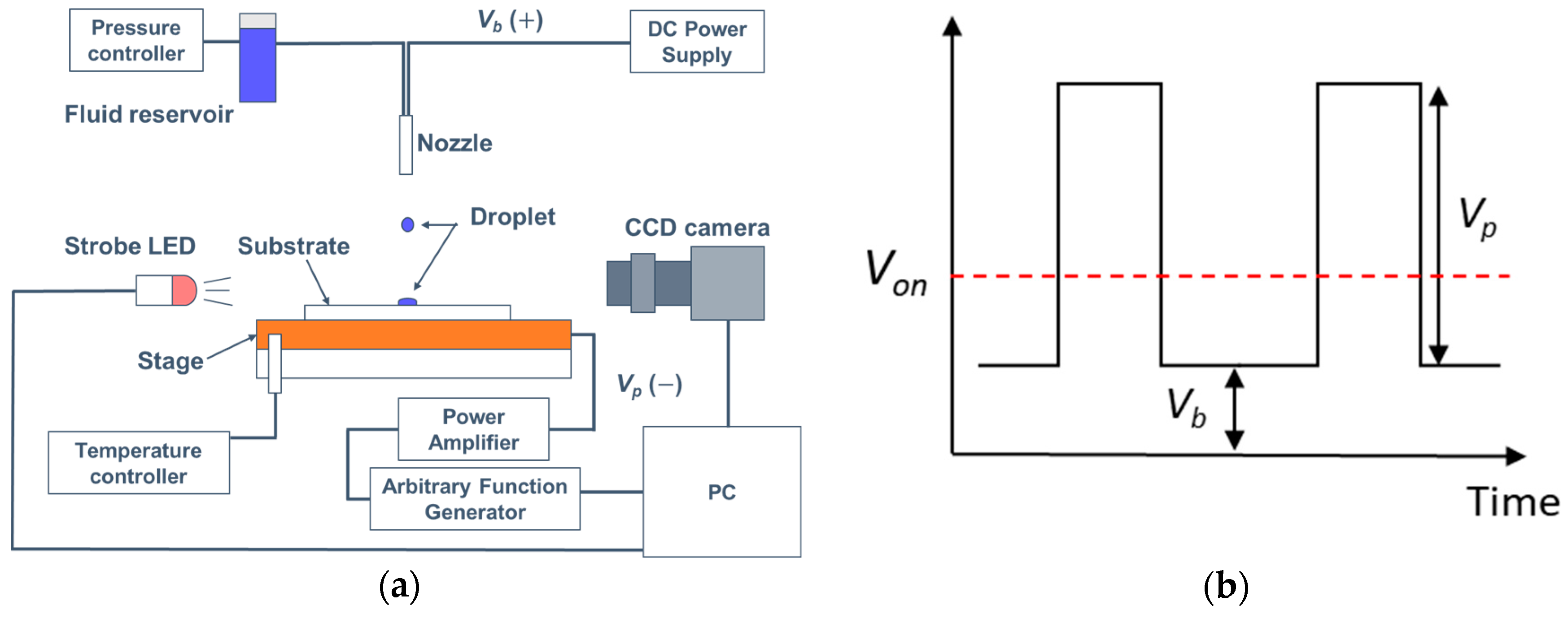
Figure 2.
Onset voltage, Von, as a function of distance between nozzle and substrate. Calculated data is based on Equation (1), and experimental data were obtained using Nozzle A (dn = 30 μm).
Figure 2.
Onset voltage, Von, as a function of distance between nozzle and substrate. Calculated data is based on Equation (1), and experimental data were obtained using Nozzle A (dn = 30 μm).

Figure 3.
Schematics of nozzle: ρ = density of ink, γ = surface tension of ink, υ = viscosity of ink, H = approximate ink column height from ink reservoir to free end of nozzle, b = radius of capillary far above nozzle, h = distance between nozzle and substrate, hm = meniscus height, dn = inner diameter of nozzle, and l = total length of thinnest part of nozzle.
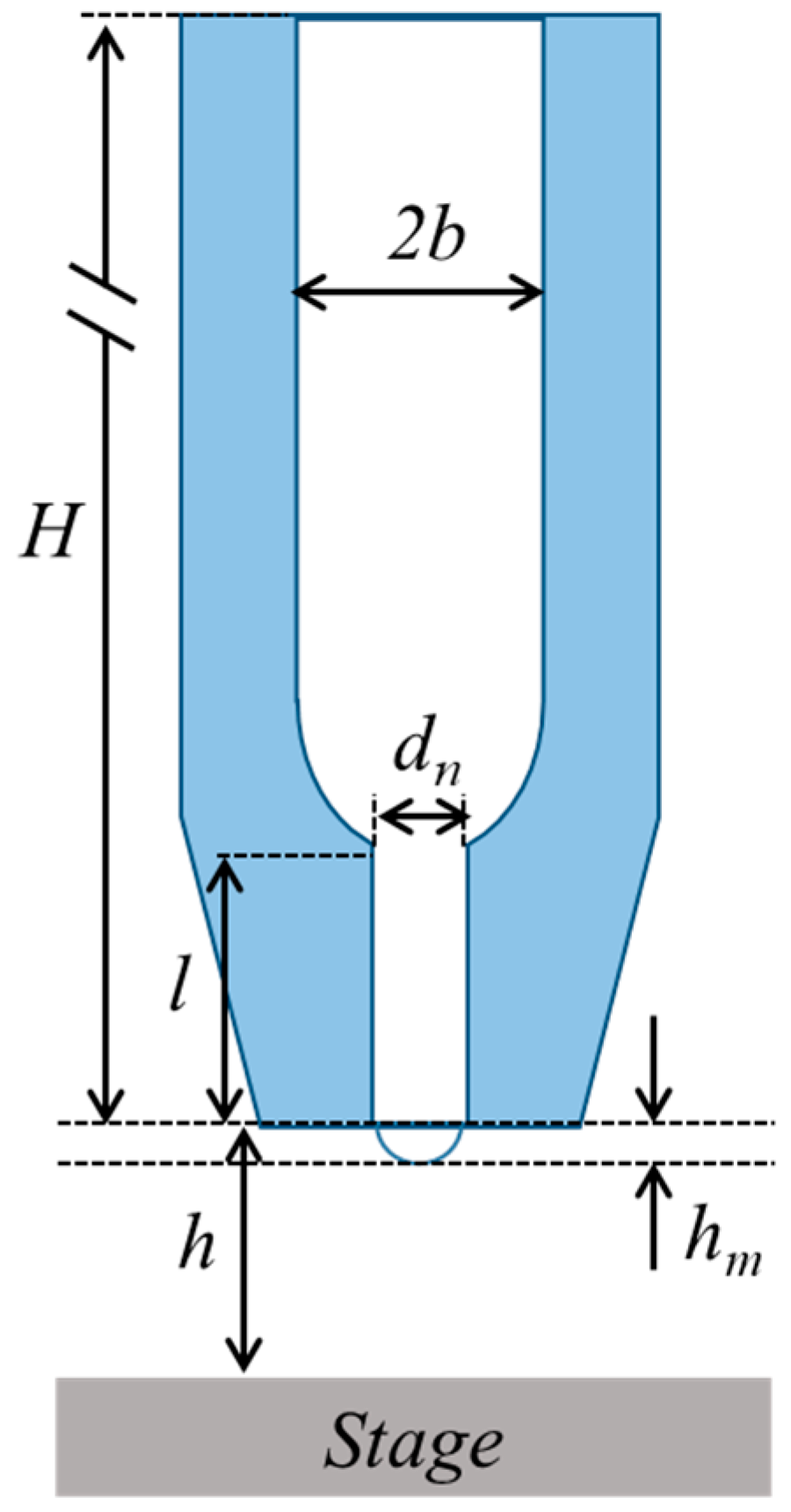
Figure 4.
Printed drops of Ag ink with various pulsation frequencies of 1, 10, 30, and 1000 Hz for (a) overdamped system (Nozzle A; Γ = 2.0) and (b) underdamped system (Nozzle B; Γ = 0.8) at the minimum pulse voltages of jetting of 150 V and 300 V, respectively. The two nozzles have the same diameter dn of 30 μm and the same natural frequency fc of 224 Hz, while they have different damping ratios.

Figure 5.
Measured jetting frequency as a function of pulsation frequency. Jetting frequency is in good agreement with pulsating frequency for overdamped system (Nozzle A; Γ = 2.0), while jetting frequency does not increase with pulsation frequency at a few Hz for underdamped system (Nozzle B; Γ = 0.8).

Figure 6.
Natural frequency ratio of jetting as a function of natural frequency ratio of pulsation for overdamped nozzles A (fc = 224 Hz) and C (fc = 448 Hz). Pulse voltages of 150 V and 220 V are the minimum jetting voltages for nozzles A and C, respectively, while 250 V and 300 V are the increased pulse voltages of jetting for nozzles A and C, respectively.


Table 1.
Parameters of the experimental set-up.
| Parameter | Nozzle # | ||
|---|---|---|---|
| A | B | C | |
| Approximate ink column height, H (m) | 0.2 | ||
| Distance between nozzle and substrate, h (µm) | 100 | ||
| Inner diameter of nozzle, dn (µm) | 30 | 15 | |
| Radius of the capillary far above the nozzle, b (µm) | 375 | 120 | 60 |
| Total length of the thinnest part, l (mm) | 3.0 | 1.2 | 1.2 |
| Bias voltage, Vb (V) | 650 | 620 | 450 |
Table 2.
Calculated natural frequency and damping ratio of three different nozzles.
| Parameter | Nozzle # | ||
|---|---|---|---|
| A | B | C | |
| Natural frequency inside the capillary, fc (Hz) | 224 | 224 | 448 |
| Damping ratio of the system, | 2.0 | 0.78 | 1.6 |
© 2018 by the authors. Licensee MDPI, Basel, Switzerland. This article is an open access article distributed under the terms and conditions of the Creative Commons Attribution (CC BY) license (http://creativecommons.org/licenses/by/4.0/).
Share and Cite
MDPI and ACS Style
Kim, S.H.; Kang, H.; Kang, K.; Lee, S.H.; Cho, K.H.; Hwang, J.Y. Effect of Meniscus Damping Ratio on Drop-on-Demand Electrohydrodynamic Jetting. Appl. Sci. 2018, 8, 164. https://doi.org/10.3390/app8020164
AMA Style
Kim SH, Kang H, Kang K, Lee SH, Cho KH, Hwang JY. Effect of Meniscus Damping Ratio on Drop-on-Demand Electrohydrodynamic Jetting. Applied Sciences. 2018; 8(2):164. https://doi.org/10.3390/app8020164
Chicago/Turabian StyleKim, Samuel Haedong, Heuiseok Kang, Kyungtae Kang, Sang Ho Lee, Kwan Hyun Cho, and Jun Young Hwang. 2018. "Effect of Meniscus Damping Ratio on Drop-on-Demand Electrohydrodynamic Jetting" Applied Sciences 8, no. 2: 164. https://doi.org/10.3390/app8020164
Note that from the first issue of 2016, this journal uses article numbers instead of page numbers. See further details here.