Improvement of RF Wireless Power Transmission Using a Circularly Polarized Retrodirective Antenna Array with EBG Structures


Abstract
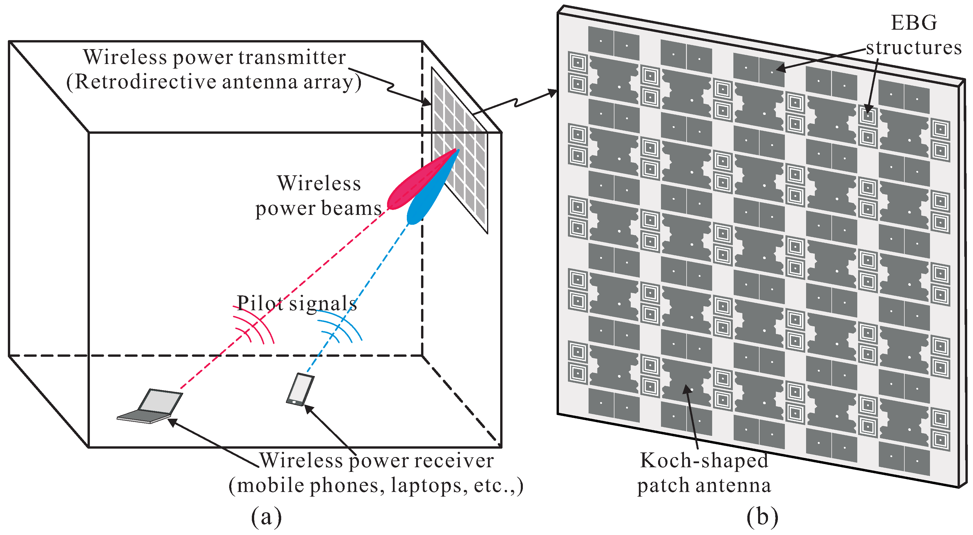
:1. Introduction
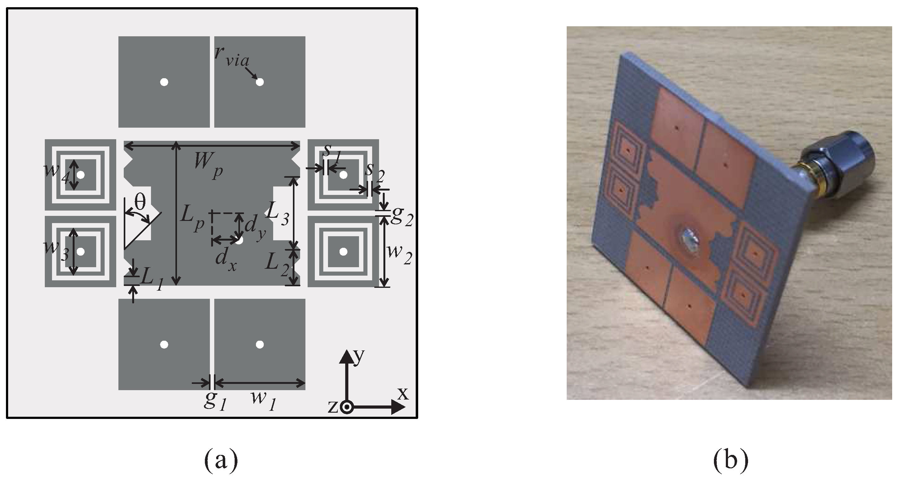
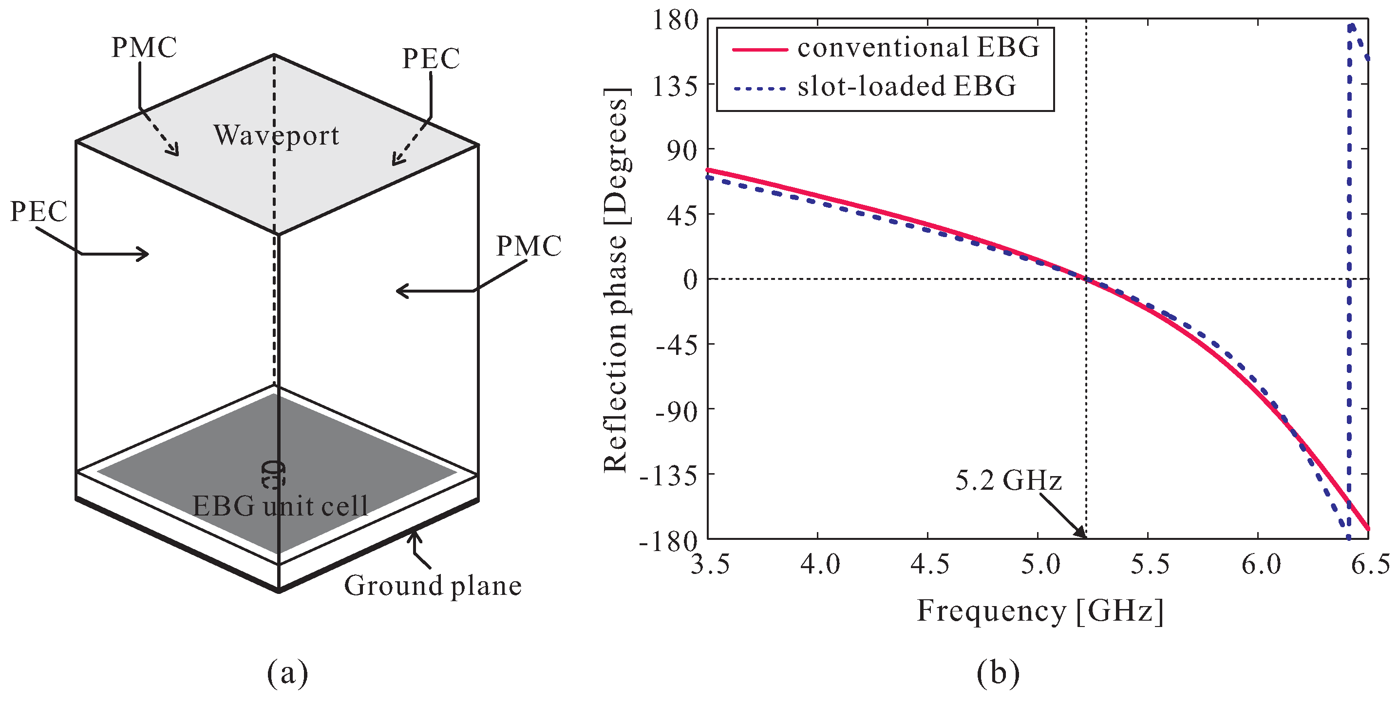
2. Design of the Proposed RDA with the EBGs
2.1. Mutual Coupling Reduction with the Presence of the EBGs
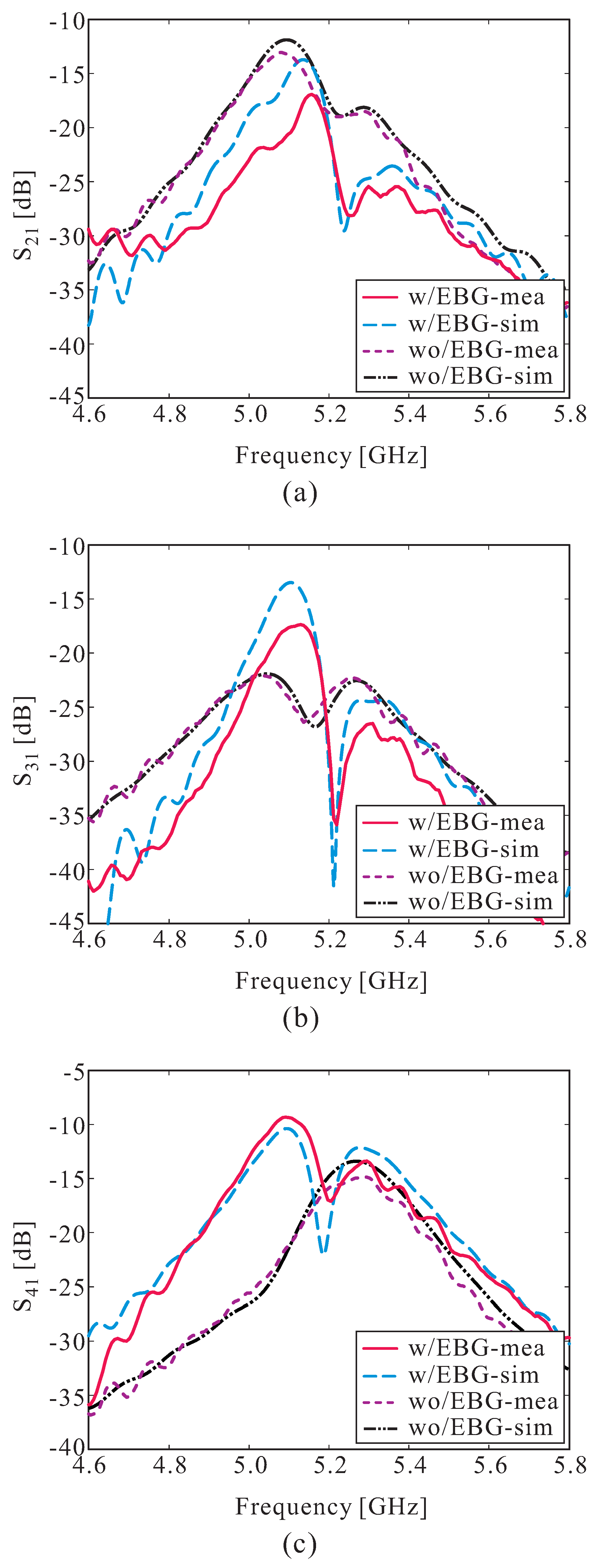
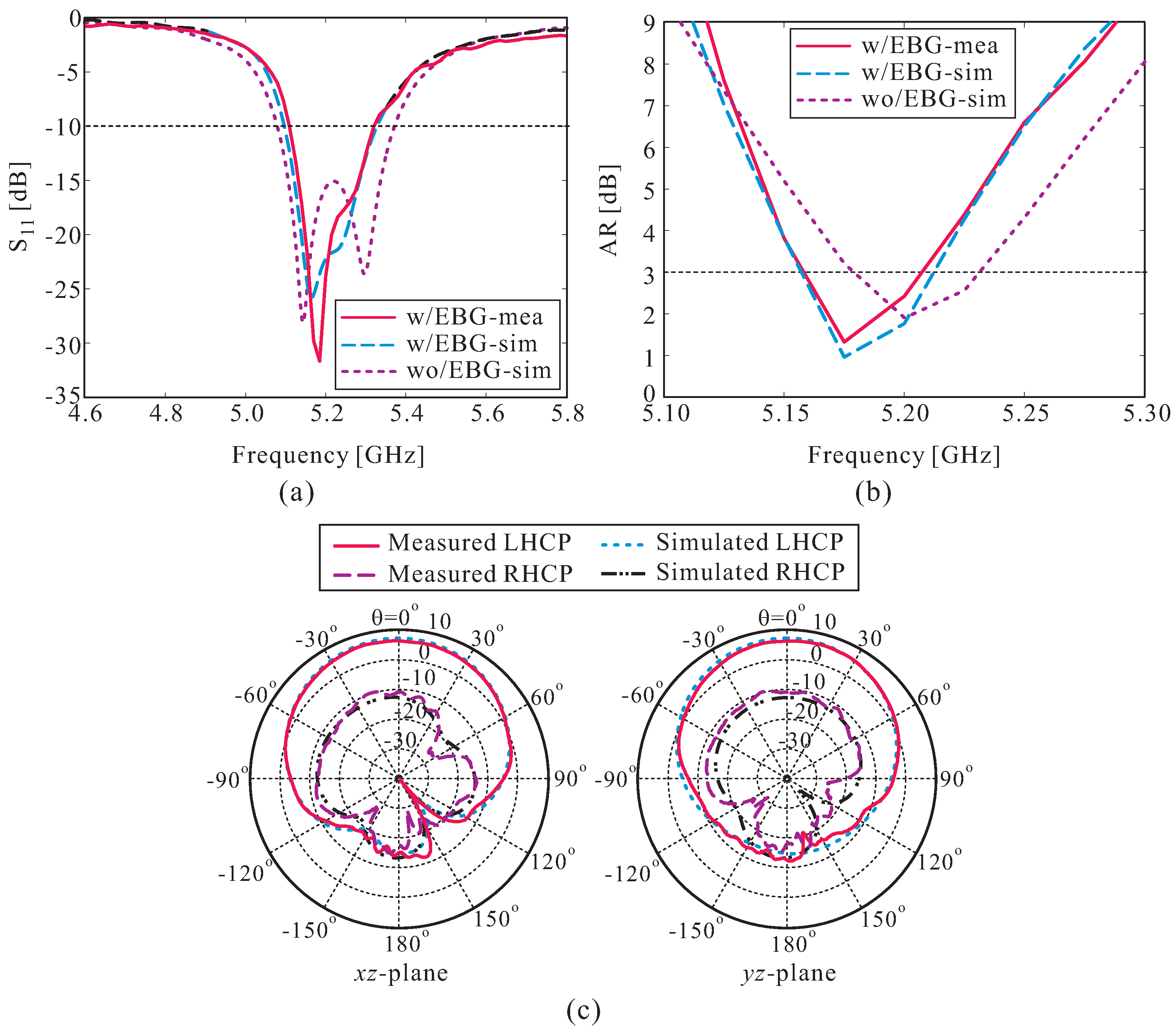
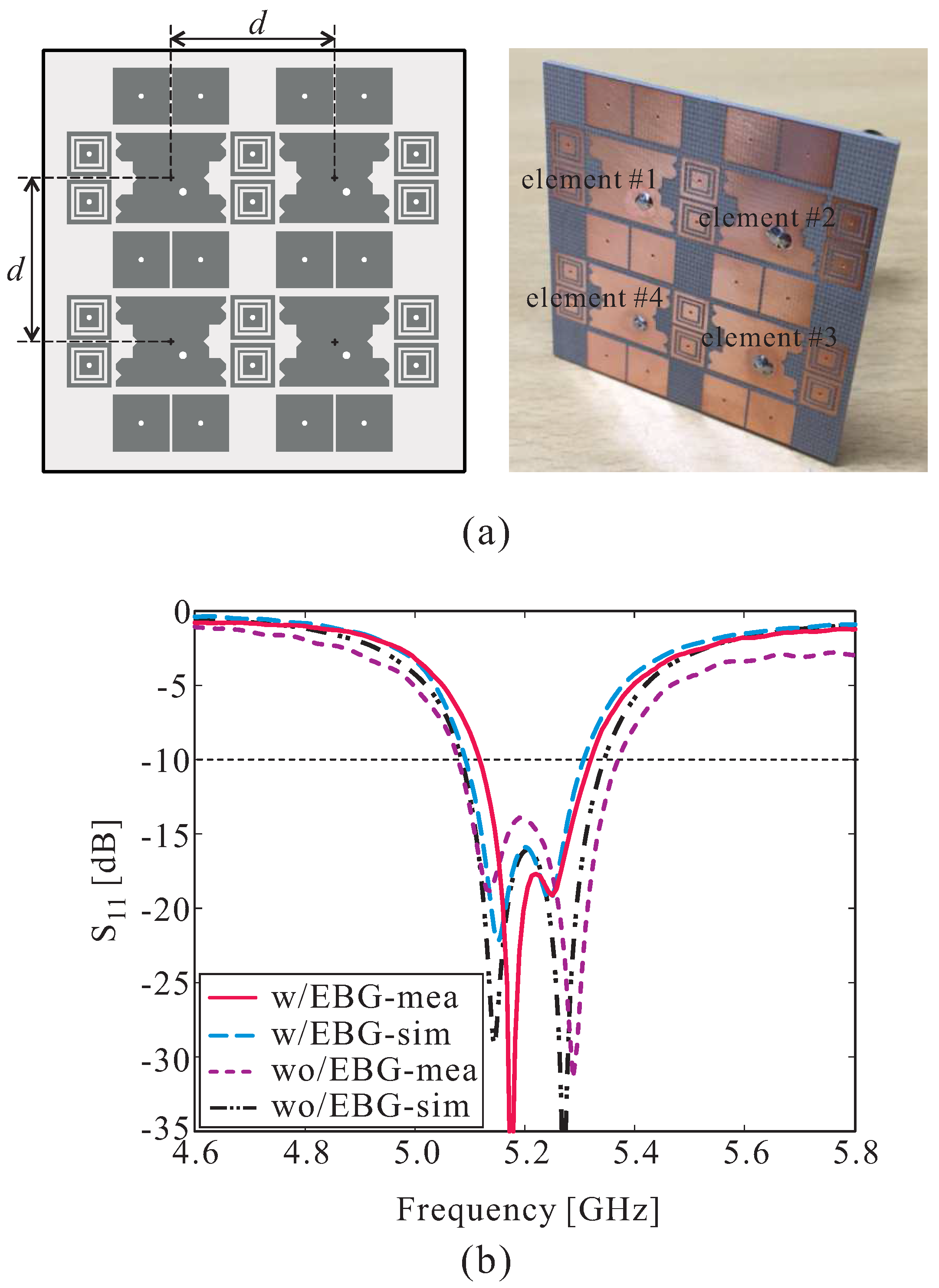
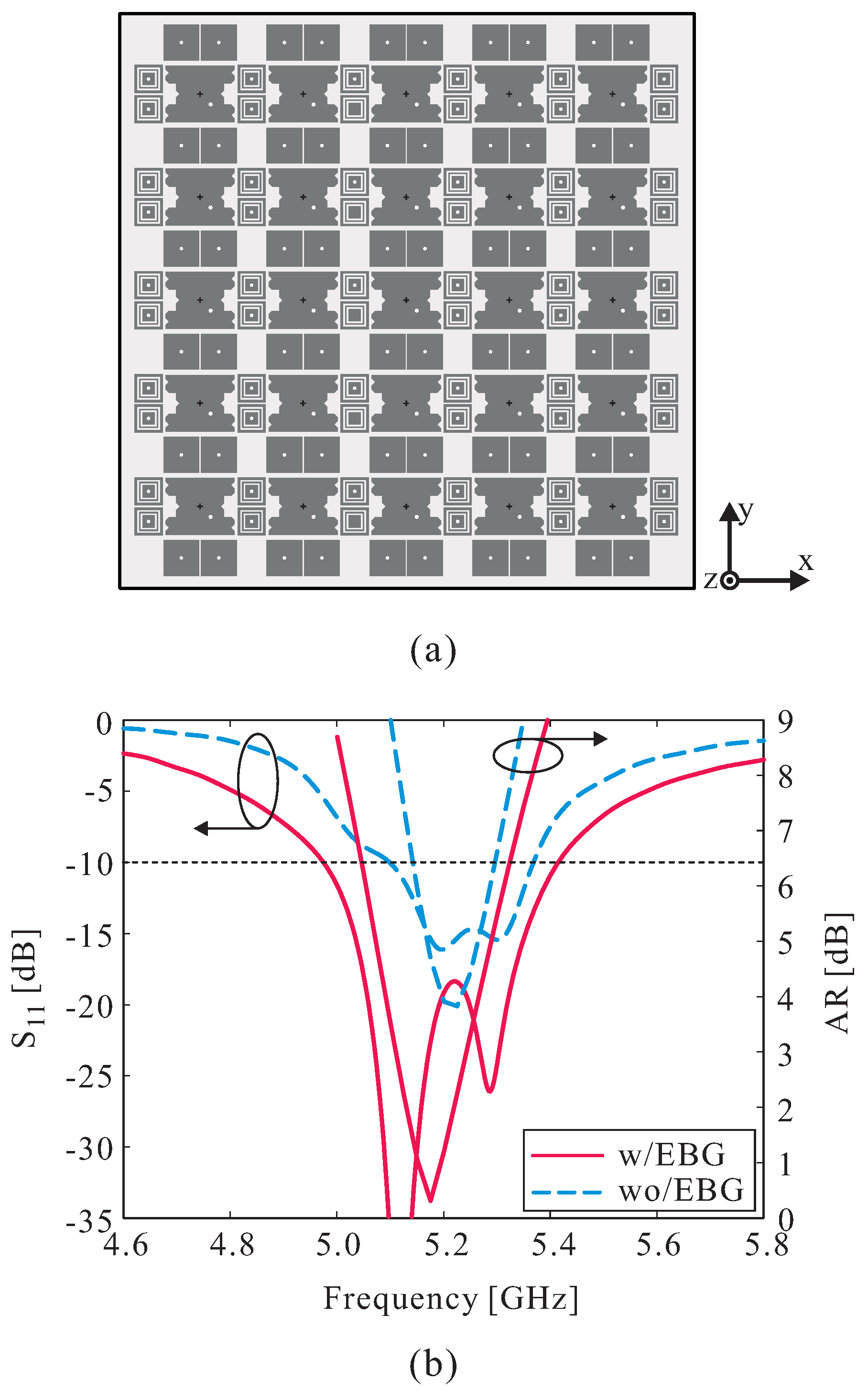
2.2. Performance of RDA with the EBGs
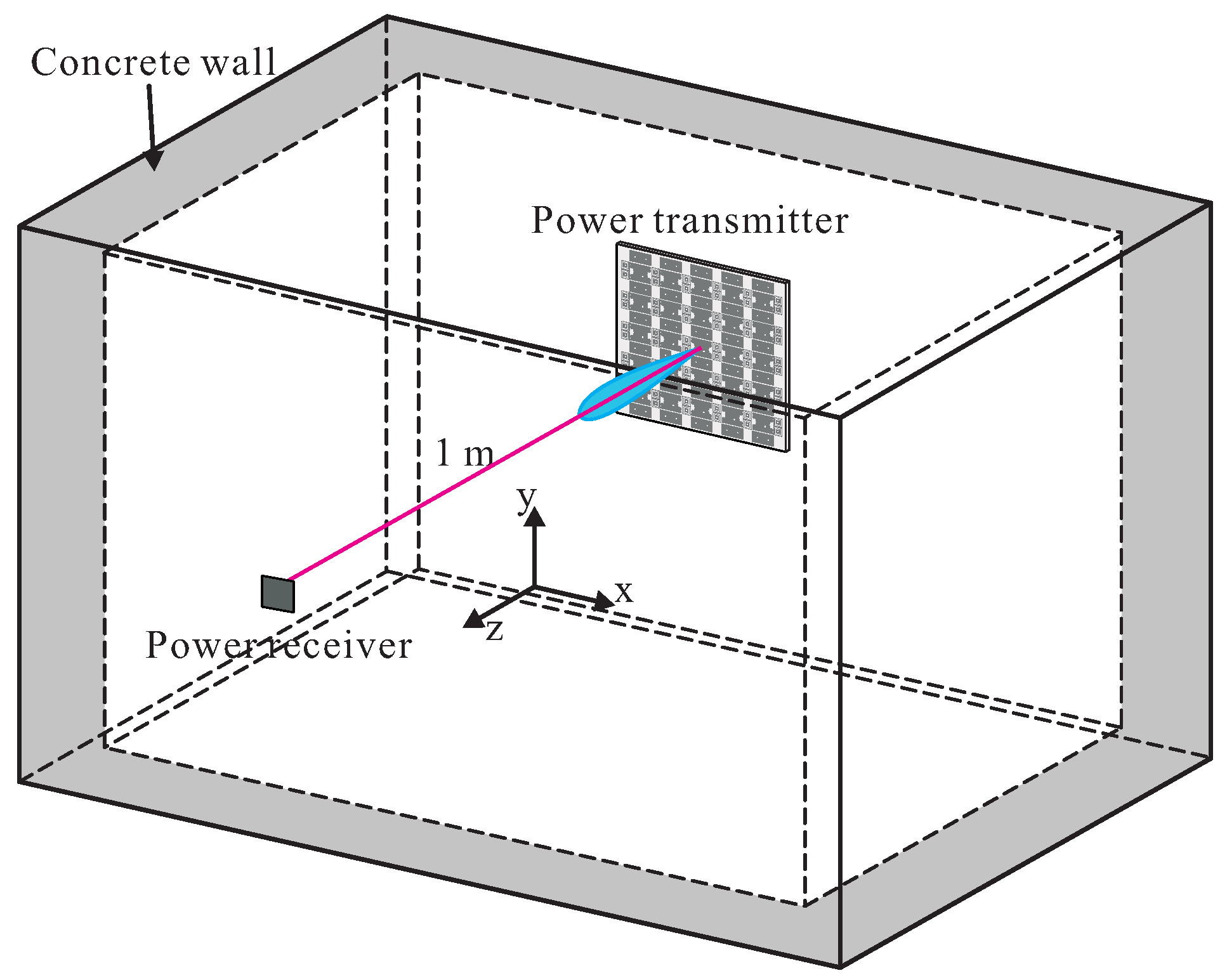
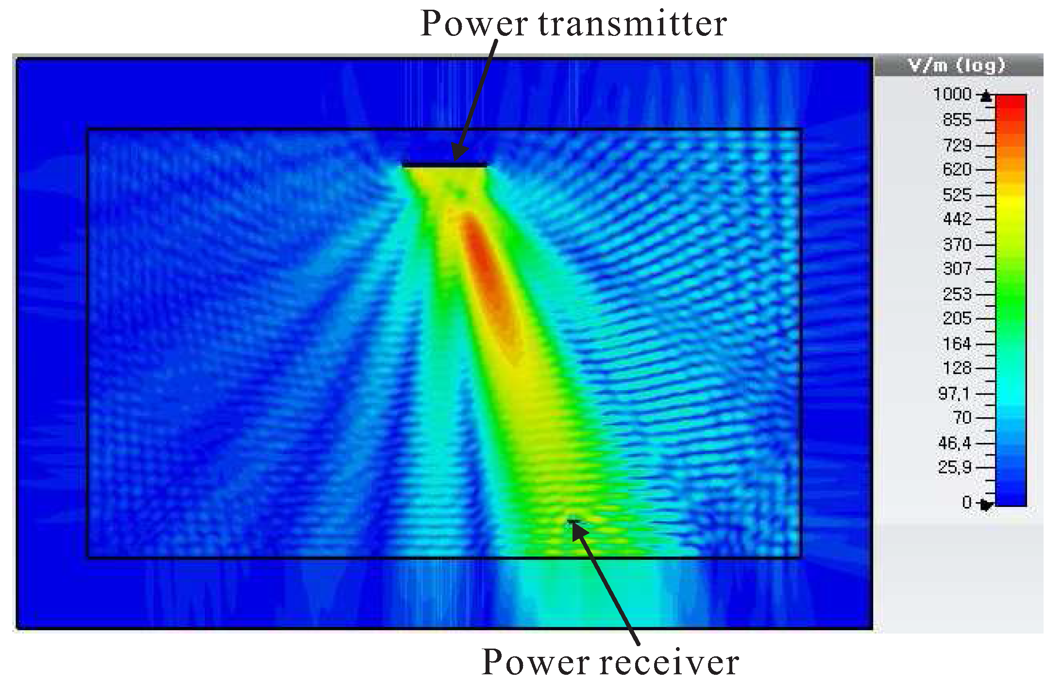
3. Performance in Wireless Power Transmission
4. Conclusions
Acknowledgments
Author Contributions
Conflicts of Interest
References
- Goshi, D.S.; Leong, K.M.K.H.; Itoh, T. Recent advances in retrodirective system technology. In Proceedings of the 2006 IEEE Radio and Wireless Symposium, San Diego, CA, USA, 17–19 October 2006; pp. 459–462. [Google Scholar]
- Matsumoto, H. Research on solar power satellites and microwave power transmission in Japan. IEEE Microw. Mag. 2002, 3, 36–45. [Google Scholar] [CrossRef]
- Mekikis, P.V.; Kartsakli, E.; Antonopoulos, A.; Alonso, L.; Verikoukis, C. Connectivity analysis in clustered wireless sensor networks powered by solar energy. IEEE Trans. Wirel. Commun. 2018, PP, 1. [Google Scholar] [CrossRef]
- Fusco, V.F. Retrodirective array techniques for ACC vehicular augmentation. In Proceedings of the IEE Colloquium on Antennas for Automotives (Ref. No. 2000/002), London, UK, 10 March 2000. [Google Scholar]
- Li, Y.; Jandhyala, V. Design of retrodirective antenna array for short-range wireless power transmission. IEEE Trans. Antennas Propag. 2012, 60, 206–211. [Google Scholar] [CrossRef]
- Sharp, E.D.; Diab, M.A. Van Atta reflector array. IRE Trans. Antennas Propag. 1960, 8, 436–438. [Google Scholar] [CrossRef]
- Pon, C.Y. Retrodirective array using the heterodyne technique. IEEE Trans. Antennas Propag. 1964, 12, 176–180. [Google Scholar] [CrossRef]
- Ali, A.A.M.; El-Shaarawy, H.B.; Aubert, H. Millimeter-wave substrate integrated waveguide passive Van Atta reflector array. IEEE Trans. Antennas Propag. 2013, 61, 1465–1470. [Google Scholar] [CrossRef]
- Tseng, W.-J.; Chung, S.-B.; Chang, K. A planar Van Atta array reflector with retrodirectivity in both E-plane and H-plane. IEEE Trans. Antennas Propag. 2000, 48, 173–175. [Google Scholar] [CrossRef]
- Fusco, V.F.; Buchanan, N. Retrodirective array performance in the presence of near field obstructions. IEEE Trans. Antennas Propag. 2010, 58, 982–986. [Google Scholar] [CrossRef]
- Wang, X.; Lu, M. Microwave power transmission based on retro-reflective beamforming. In Wireless Power Transfer—Fundamentals and Technologies; Coca, E., Ed.; In Tech: London, UK, 2016. [Google Scholar]
- Wang, X.; Sha, S.; He, J.; Guo, L.; Lu, M. Wireless power delivery to low-power mobile devices based on retro-reflective beamforming. IEEE Antennas Wirel. Propag. Lett. 2014, 13, 919–922. [Google Scholar] [CrossRef]
- Zhou, H.; Hong, W.; Tian, L.; Jiang, X.; Zhu, X.-C.; Jiang, M.; Cheng, L.; Zhuang, J.-X. A retrodirective antenna array with polarization rotation property. IEEE Trans. Antennas Propag. 2014, 62, 4081–4088. [Google Scholar] [CrossRef]
- Ren, Y.-J.; Chang, K. New 5.8-GHz circularly polarized retrodirective rectenna arrays for wireless power transmission. IEEE Trans. Microw. Theory Tech. 2006, 54, 2970–2976. [Google Scholar]
- Miao, Z.-W.; Hao, Z.-C.; Yuan, Q. A passive circularly polarized Van Atta reflector for vehicle radar applications. IEEE Antennas Wirel. Propag. Lett. 2017, 16, 2254–2257. [Google Scholar] [CrossRef]
- Fairouz, M.; Saed, M. A retrodirective array with reduced surface waves for wireless power transfer applications. Prog. Electromagn. Res. C 2014, 55, 179–186. [Google Scholar] [CrossRef]
- Zhang, X.; Cheng, Z.; Gui, Y. Design of a new built-in UHF multi-frequency antenna sensor for partial discharge detection in high-voltage switchgears. Sensors 2016, 16, 1170. [Google Scholar] [CrossRef] [PubMed]
- Fukusako, T. Broadband characterization of circularly polarized waveguide antennas using L-shaped probe. J. Electromagn. Eng. Sci. 2017, 17, 1–8. [Google Scholar] [CrossRef]
- Jin, Y.; Tak, J.; Choi, J. Quadruple band-notched trapezoid UWB antenna with reduced gains in notch bands. J. Electromagn. Eng. Sci. 2016, 16, 35–43. [Google Scholar] [CrossRef]
- Ha-Van, N.; Seo, C. A single-feed port HF-UHF dual-band RFID tag antenna. J. Electromagn. Eng. Sci. 2017, 17, 233–237. [Google Scholar] [CrossRef]
- Yang, F.; Rahmat-Samii, Y. Electromagnetic Band Gap Structures in Antenna Engineering; Cambridge University Press: Cambridge, UK, 2009. [Google Scholar]
- Azarbar, A.; Ghalibafan, J. A compact low-permittivity dual-layer EBG structure for mutual coupling reduction. Int. J. Antennas Propag. 2011, 2011, 237454. [Google Scholar] [CrossRef]
- Lamminen, A.E.I.; Vimpari, A.R.; Saily, J. UC-EBG on LTCC for 60-GHz frequency band antenna applications. IEEE Trans. Antennas Propag. 2009, 57, 2904–2912. [Google Scholar] [CrossRef]


| Without EBGs | With EBGs | ||
|---|---|---|---|
| Inter-element Spacing | 0.5 | 0.4 | 0.4 |
| Received Power (W) | 1.339 | 0.827 | 0.930 |
| Received Power (W) | Improvement (%) | |||
|---|---|---|---|---|
| Moving along x-direction | 0.18 m | With EBGs | 0.881 | 21.02 |
| Without EBGs | 0.728 | |||
| 0.36 m | With EBGs | 0.649 | 20.41 | |
| Without EBGs | 0.539 | |||
| Moving along y-direction | 0.18 m | With EBGs | 0.879 | 16.58 |
| Without EBGs | 0.754 | |||
| 0.36 m | With EBGs | 0.656 | 12.91 | |
| Without EBGs | 0.581 | |||
© 2018 by the authors. Licensee MDPI, Basel, Switzerland. This article is an open access article distributed under the terms and conditions of the Creative Commons Attribution (CC BY) license (http://creativecommons.org/licenses/by/4.0/).
Share and Cite
Trinh-Van, S.; Lee, J.M.; Yang, Y.; Lee, K.-Y.; Hwang, K.C. Improvement of RF Wireless Power Transmission Using a Circularly Polarized Retrodirective Antenna Array with EBG Structures. Appl. Sci. 2018, 8, 324. https://doi.org/10.3390/app8030324
Trinh-Van S, Lee JM, Yang Y, Lee K-Y, Hwang KC. Improvement of RF Wireless Power Transmission Using a Circularly Polarized Retrodirective Antenna Array with EBG Structures. Applied Sciences. 2018; 8(3):324. https://doi.org/10.3390/app8030324
Chicago/Turabian StyleTrinh-Van, Son, Jong Min Lee, Youngoo Yang, Kang-Yoon Lee, and Keum Cheol Hwang. 2018. "Improvement of RF Wireless Power Transmission Using a Circularly Polarized Retrodirective Antenna Array with EBG Structures" Applied Sciences 8, no. 3: 324. https://doi.org/10.3390/app8030324