Flexural Performance of Transparent Plastic Bar Reinforced Concrete


1
School of Architecture, Seoul National University of Science & Technology, 232 Gongneung-ro, Nowon-gu, Seoul 01811, Korea
2
Institute of Construction Technology, Seoul National University of Science & Technology, 232 Gongneung-ro, Nowon-gu, Seoul 01811, Korea
*
Author to whom correspondence should be addressed.
Appl. Sci. 2018, 8(3), 325; https://doi.org/10.3390/app8030325
Submission received: 17 December 2017
/
Revised: 20 February 2018
/
Accepted: 21 February 2018
/
Published: 26 February 2018
(This article belongs to the Section Materials Science and Engineering)
Abstract
:Featured Application
Reinforced transparent plastic bars applied to concrete can be used to attract the architect’s interest as an interior and exterior materials for building design and construction.
Abstract
In this study, experiments were conducted to derive a mix design for improving the flexural performance of light transparent concrete, which is attracting much attention and interest as an interior and exterior material for buildings, so that it could be easily applied in the field as a non-structural element by securing a lightweight, workability, and economic efficiency through the improvement of the concrete mix design and the use of economical materials for promoting its practical use. It was found that the mixing of polyvinyl alcohol (PVA) fiber was effective in improving the consistency by preventing the aggregate from floating due to the mixing of lightweight aggregate with a low specific gravity. The flexural performance test results showed that the load transfer factor (LTF) from the concrete matrix to the fiber was highest in the test specimens without plastic bars, followed by those with 5 and 10 mm plastic bars, respectively.
1. Introduction
Concrete is a type of material that is the most closely connected to human life and has been widely used in social infrastructure and the construction industry for the past 100 years. In recent years, technology exchange with fields other than engineering has been made to satisfy the various human requirements owing to societal development and changes. Especially in accordance with the desire to create pleasant and beautiful indoor spaces, light transparent concrete has been developed. Light transparent concrete is a material in which a large amount of optical fibers are arranged on concrete in a straight line to give light transmittance through the concrete, and its use has expanded to include that of a new type of interior and exterior material not only for building residents, but also for architects seeking changes through the continuity of discontinuous space by allowing the passage of light in addition to the separation of physical spaces, which is the original function of concrete [1,2].
Light transparent concrete was developed by Hungarian architect Aron Losconzi, and it was selected as one of the “36 Best Inventions of the Year” by TIME Magazine. Later, Aron Losconzi founded a company called “LiTraCon”, short for “Light-transmitting Concrete”. Since then, light transparent concrete has been widely used in the United States and Europe as it gives spaces a new type of functionality and improves the user satisfaction despite its high price. As light transparent concrete, however, has limitations as an architectural member using optical fibers in that its production requires labor-intensive work as the tens of thousands of thin fibers should be arranged in a straight line by human hands, and the work related to the fabrication and transport of the test specimens is ineffective due to the heavy weight of concrete (2.3 ton/m3), it is produced and sold using the pre-cast method [3]. To overcome the restrictions on the field applications of light transparent concrete due to its practical limitations in terms of economic efficiency (material and labor costs) and workability (mass production), researches are continuously being conducted to overcome the existing limitations of light transparent concrete, and thus to increase its utilization rate in the field [4].
The critical areas for improvement can largely be divided into the construction method and the material. For the construction method, a relatively low-cost plastic bar was used instead of an expensive optical fiber to greatly reduce the material cost, and a method of inserting a transparent bar of a certain size from the outside was applied to reduce the labor cost and to enable mass production [4]. In the case of the material, an artificial ultra-lightweight aggregate with a 0.6 specific gravity was used, and high-temperature and high-pressure curing within an autoclave was applied in the production with quicklime and sand with high silica contents as the main materials to ensure excellent adhesion to the concrete matrix due to its surface with an open-cell structure [5,6,7]. To reduce the weight using foams, a method of providing lightweight and heat insulation to concrete by making a foamed slurry mixed with cement, sand, and admixture materials, and forming small and fine foams (0.1–1 mm) inside the concrete matrix, was used [8]. Lastly, a basic experiment was conducted to overcome the limitations due to the heavy weight and labor-intensive work through the application of organic fibers, which demonstrated excellent ductility without lowering the consistency of concrete, to prevent a reduction in the flexural performance and ductility when a transparent bar made of plastic is placed [4].
In this study, experiments were conducted to improve the mechanical properties due to the lightweight of light transparent concrete by gradually optimizing several methods applied to overcome the existing problems. To improve the workability and to realize the field applications through the lightweight, two types of foaming agent and lightweight aggregates were used to optimize the unit weight reduction, and high-quality organic fibers were mixed to solve the problem caused by the reduced flexural performance due to the insertion of a transparent plastic bar for the purpose of improving the flexural performance of lightweight transparent concrete. In addition, mix conditions under which mass production can be achieved in the commercialization process in the construction industry with the use of low-cost materials and manufacturing methods as a whole through the derivation of the optimum flowability in which concrete can be safely placed in the specimen with the minimum compaction were proposed.
2. Materials and Experiment Program
Transparent plastic bars were used to transmit light to the concrete: the round bars were produced by Je-il Corporation (Seoul, Korea). The main properties and detailed images of such plastic bars are shown in Figure 1. The diameters of the plastic bars used in this study are 5 mm and 10 mm. PVA (polyvinyl alcohol) fiber was applied to prevent the degradation of the flexural performance due to the insertion of transparent bars, the delayed cracking, and the increased ductility [9,10,11,12]. A fiber 6 mm long was used to prevent interference between the plastic bars inserted at 10 mm intervals when the concrete was placed in the light-transmitting mold. The diameter of this fiber was 26 µm, and the specific gravity was 1.3 ± 0.1 (kg/m3). The elongation was about 8%, and the tensile strength and elastic modulus were 1200 MPa and 24.5 GPa, respectively. The detailed images of the fiber are shown in Figure 2. In response to the lightweight of light transparent concrete, cast-in-place foams were mixed with concrete. Foaming agents can be classified into a synthetic foaming agent, resin soap-based foaming agent, and hydrolyzed protein-based foaming agent depending on the specifications [13,14]. In this study, a synthetic foaming agent and protein-based foaming agent, which are mainly applied in the field, were used to analyze the stable state and the unit weight of foams according to the type of foaming agent. The foams were applied through the pre-foaming method, which has advantages in that it can control the density of the cured body by adjusting the amount of foams, ensure excellent workability, and produce spherical foams [2]. The pH (25 °C) of each foaming agent was 7 ± 0.5, and the specific gravity was 1 ± 0.5 (kg/m3) at room temperature (20 °C). Fly ash was also used in this study to confirm its ability for enhancing flowability and reducing unnecessary internal air voids. Its specific gravity and specific surface area were 2.22 g/cm3 and 3430 cm2/g, respectively.
The physical properties of the used lightweight aggregates are summarized in Table 1.
2.1. Experiment Methodology
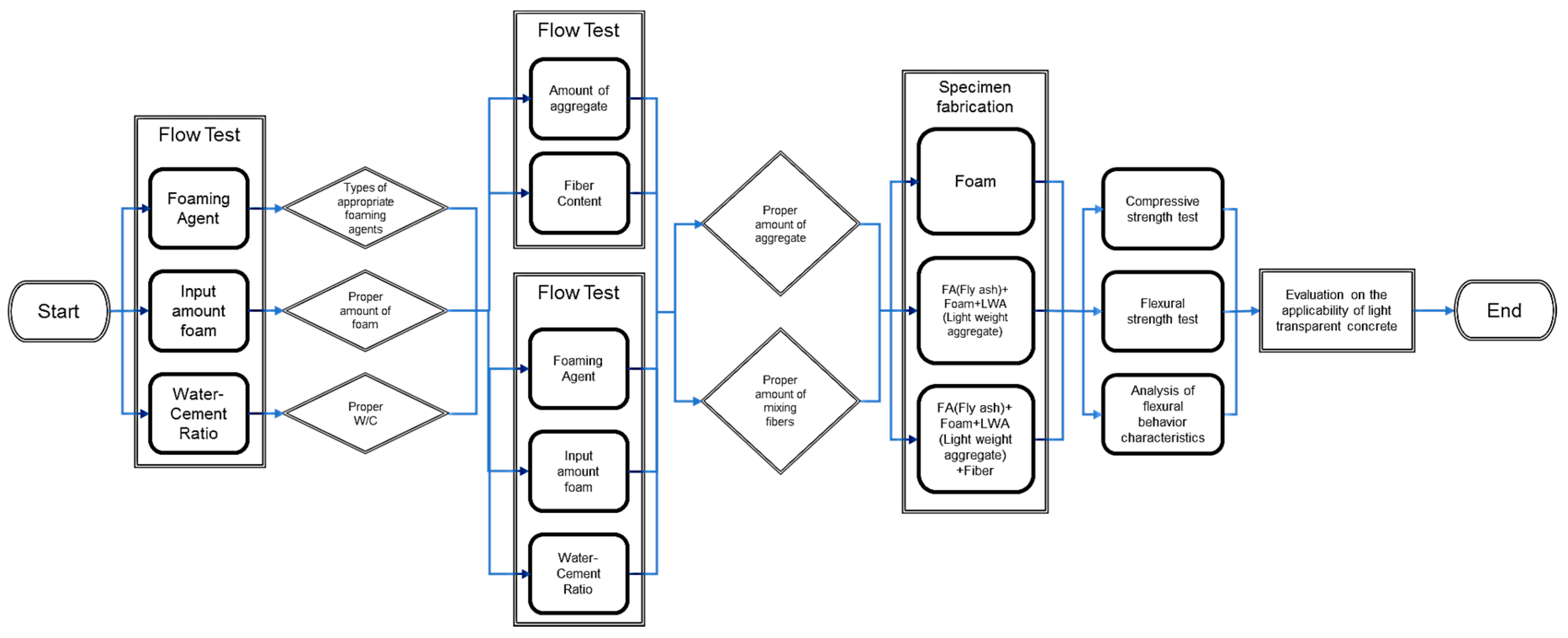
An experiment was conducted in four steps to derive the optimum flowability for securing workability in the process of acquiring a lightweight for light transparent concrete (Table 2, Figure 3). In the first step, two foaming agents with different specifications were used to determine the proper amounts and types of foaming agents suitable for this study. In addition, the amount of foam and the appropriate water-cement ratio were derived and applied to the next research step. In the second step, a lightweight aggregate for strength improvement was gradually added to the foamed concrete to which the selected foaming agent and the water-cement ratio mixing amount were applied, and the flowability was identified by mixing fly ash to reduce the internal voids and improve the flowability. In the third step, three kinds of test specimens were fabricated using the derived mix design, and their physical properties were tested. In the final step, the characteristics of the flexural behavior in the load transfer section were analyzed using a load-displacement curve derived from the flexural load test. As a result, the optimum mix proportion of light transparent concrete with improved flexural performance that ensures excellent workability in the construction process and superior delay effects on crack progression at failure was derived through the above four steps.
2.2. Mixing Test to Derive the Optimum Mix Proportion
Foam and lightweight aggregates were used in place of aggregates to reduce the weight of light transparent concrete, and thus to improve its workability in the production and movement of members. Measurement of the unit weight and a slump flow test were carried out. In the slump flow test, the flow of the specimen using lightweight aggregate was tested in accordance with KS F 2402 (Method of test for slump of concrete) [15], and the flow of concrete with the foams was tested in accordance with KS F 4039 (Cast-in-Place Foam Concrete) [16]. In the slump test of foamed concrete, the changes in the consistency of the slurries according to the type of foaming agent were confirmed by using foaming agents with different specifications, and the foaming agent with excellent holding power and without foam destruction in the slurry was selected. In addition, the test was conducted by specifying the water-cement ratios and foam input ranges, which are factors of the changes in flowability, into 40, 45, and 50% and 500, 600, and 700 L/m3, respectively, and the proportions of the mix corresponding to Nos. 1–18 in Table 3 were planned as the mix design. In the workability test (Nos. 19–33), according to the changes in the lightweight aggregate ratio and the fiber mixing amount, the two types of foam amounts (350 and 525 L/m3) and the fibers were mixed at three mixing ratios (0.1, 0.2, and 0.3%) to confirm the consistency and flowability of concrete. In the same mix proportion, 25% of the cement volume was replaced with fly ash under the same conditions to investigate the flowability changes (specimen Nos. 27–34) by mixing fly ash.
3. Results
3.1. Workability by Type of Foaming Agent
3.1.1. Mixing Test to Derive the Optimum Mix Proportion
The results of the flowability evaluation according to the changes in the amounts of foaming agent and lightweight aggregate, and the changes in the fiber contents, are shown in Figure 4 and Figure 5, respectively. The results of the workability test of foamed concrete using a synthetic foaming agent and an animal-protein-based foaming agent confirmed that the flow decreased as the input amount of foam increased. This suggests that the increase in the fine foam particles led to the decrease of the flowability in the concrete [17]. In addition, it was confirmed that this flow reduction was mitigated by the increase of the water-cement ratio. The specimen using an animal-protein-based foaming agent underwent foam destruction in the slurry (defoaming phenomenon) after mixing. In addition, the phenomenon of flow reduction due to an increase in the input amount of foam was not clearly identified. As a result of the flowability test, it was confirmed that the foam particles were relatively well distributed and maintained in the foamed concrete using the synthetic foaming agent, and thus, the synthetic foaming agent was found to be suitable for the purposes of workability improvement and lightweight realization for light transparent concrete. In addition, an approximate 215–230 mm flow was confirmed in the 45% water-cement ratio, which was determined to be the appropriate flowability range considering that lightweight aggregate and fibers are to be mixed in the future. It was found that the water-cement ratio suitable for this study was 45%, and the proper input ratio of foam was determined to be 50–60% of the total volume [18,19,20].
The results of the workability test according to the changes in the lightweight aggregate ratio and the fiber content are shown in Figure 5. In the specimen without fly ash, the flowability decreased due to the increase of the consistency with an increase in the fiber content. The specimen using the 350 kg/m3 lightweight aggregate showed flowability reduction, unlike in the specimen using the 175 kg/m3 lightweight aggregate. In the case of the specimen in which fly ash 25% of the cement volume was added, the increase of the viscosity occurred at the more than 0.1% fiber content and it was confirmed that the fiber content and the flow were inversely proportional to each other.
The results of the workability test using the foaming agent showed that the flow decreased as the foam input amount increased, and the increase in the water-cement ratio led to increased flow. In addition, it was found that the synthetic foaming agent rather than the animal-protein-based foaming agent faithfully performed a ball-bearing role without being destroyed in the slurry. The specimen with lightweight aggregate exhibited a superior consistency when fly ash 25% of the cement volume was added, and the flowability of the specimen with 17.5% lightweight aggregate compared to the total volume was found to be superior to that of the specimen with 52.5% lightweight aggregate compared to the total volume. In addition, the flow of the specimen mixed with 0.2% fiber among the specimens containing 17.5% lightweight aggregate was 180 mm, showing consistency suitable for placement, and it was confirmed that the trouble caused by the aggregate that floats to the top surface was solved by the addition of lightweight aggregate. The optimum mix proportion derived from the above results was 45% for the water-cement ratio, C × 25% for the fly ash, 17.5% for the ALA (autoclaved lightweight concrete aggregate), 52.5% for SFA (synthetic foaming agent), and 0.2% for the fiber content.
3.1.2. Mechanical Tests from Optimum Mix Proportion
Test specimens for compressive and flexural strength tests were fabricated using the mix proportions derived from the preceding tests. The mix design for specimen fabrication is shown in Table 4. A specimen with a 100 mm diameter and a 200 mm height was fabricated by referring to KS F 2405 (Concrete Compressive Strength Test Method) to investigate the compressive strength characteristics [21], and a 100 × 100 × 400 mm3 specimen was manufactured in accordance with KS F 2566:2014 (Test Method for the Flexural Performance of Fiber-reinforced Concrete) to examine the flexural behavior characteristics [22]. For the test, light transparent concrete in which 5 and 10 mm plastic bars were inserted at 10 mm intervals was manufactured along with the general flexural test specimen to investigate the flexural behavior characteristics of light transparent concrete into which the bars are inserted. The reason that the diameters of the two types of plastic bar (5 and 10 mm) and the intervals between the bars were set to 10 mm is that as the number or diameter of the bars increases, as shown in Figure 6, the ratio of the bars to the total area of the specimens also increases, which in turn affects the light transmittance. On the contrary, the flexural strength of light transparent concrete is inversely proportional to the number of bars and their diameter. Thus, PVA fiber was added to address this. The mixing ratio of the fibers was determined to be 0.2%, which showed excellent consistency in the preceding test for deriving the optimum mix proportion.
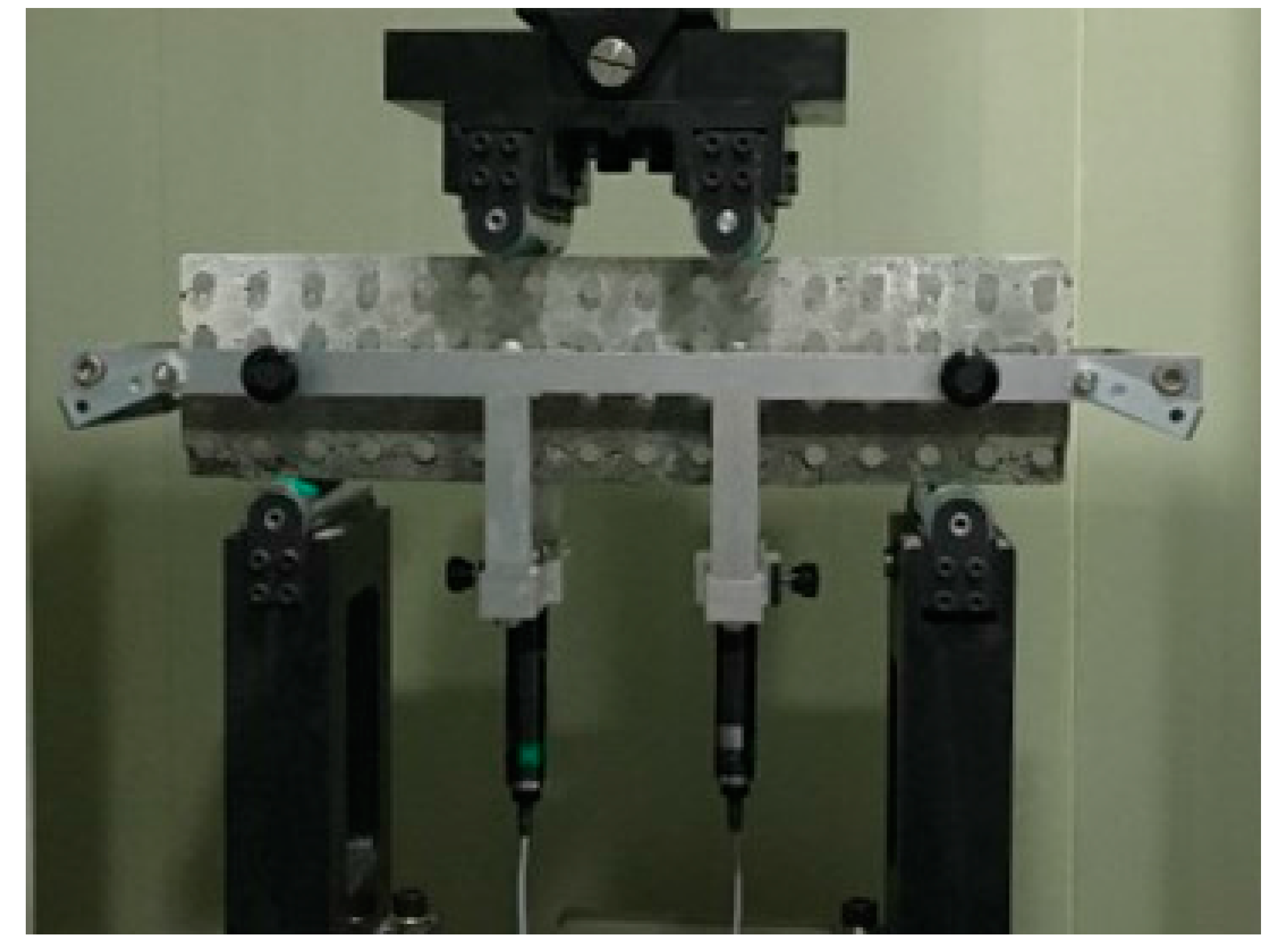
Figure 7 shows the production process for light transparent concrete. Figure 8 shows examples of the specimen images. The compressive strength test was conducted on the specimen subjected to 28-day curing, and the compressive strength was measured using a universal testing machine with a 1000 kN capacity. With respect to the flexural behavior characteristics, deflection-measuring devices (LVDTs) were attached to both sides of the center of the span to measure the deflection at the center of the specimen, and a data logger (UCAM) was used to measure and record the deflection (Figure 9). For the loading rate, the rate of increase in tensile stress was set at 0.06 ± 0.04 MPa per second.
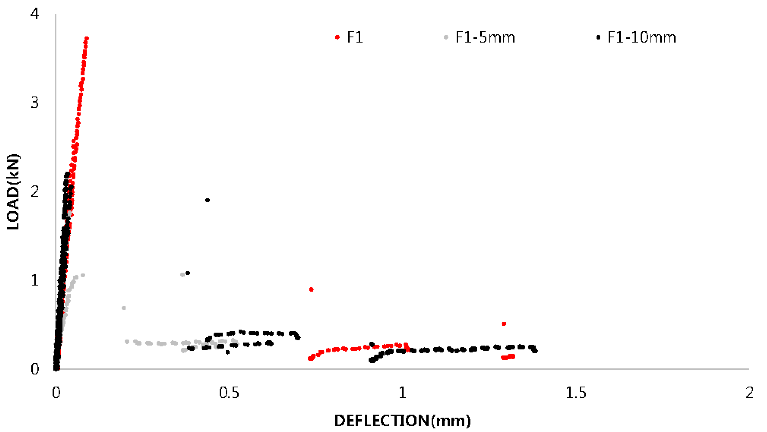
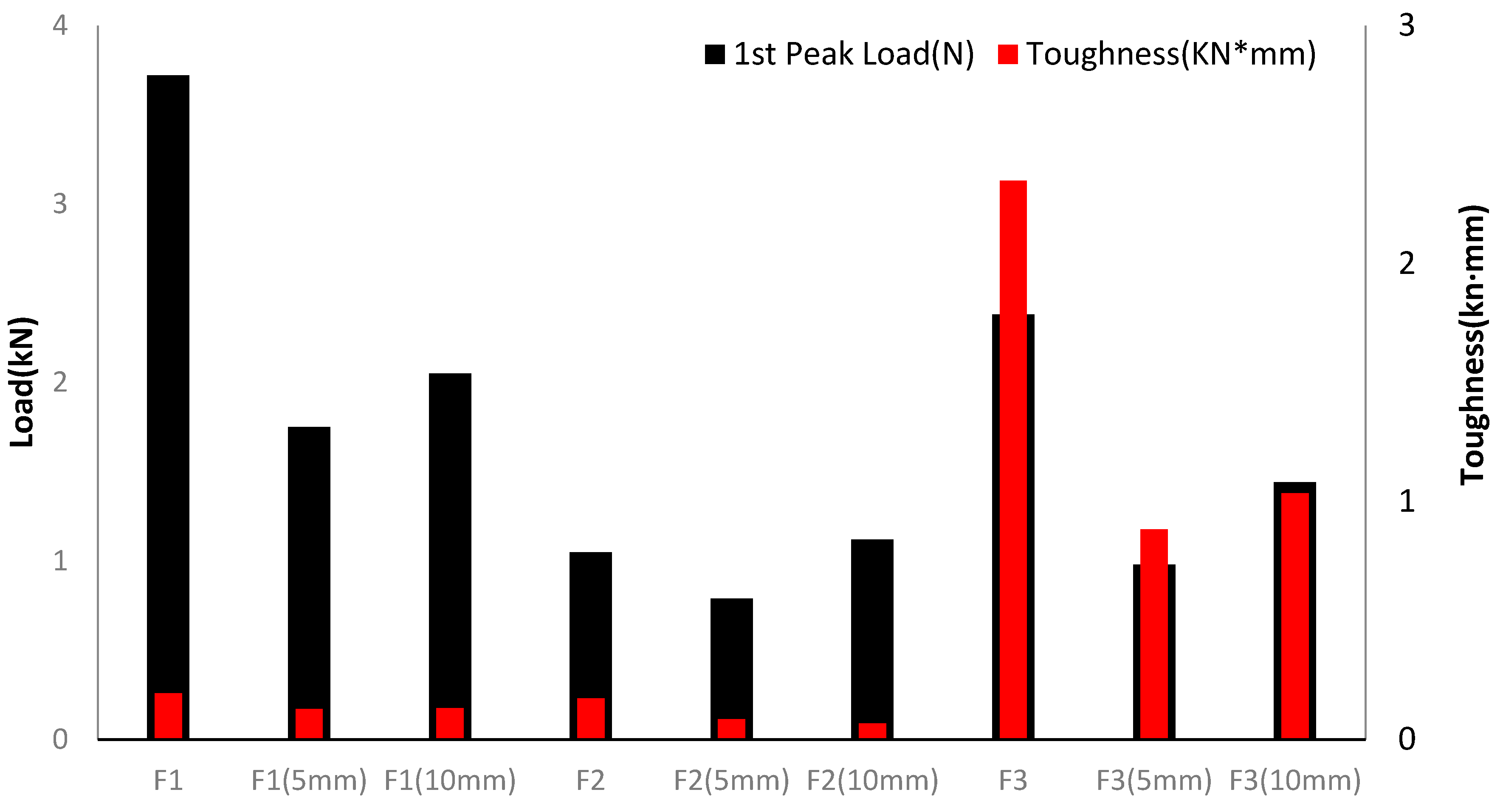
The results of the compressive strength test that was performed are shown in Figure 10. The compressive strength was considerably high in F1 (5.51 MPa), followed by F2 (2.39 MPa) and F3 (1.91 MPa). This suggests that the F1 specimen without aggregate addition exhibited a high strength as the amount of cement in it was larger than those in the remaining specimens (F2 and F3). The unit volume weight of the F1 specimen was about 944 kg/m3, and that of the F2 and F3 specimens was about 549 kg/m3. It was also confirmed that the weight was reduced by about 66% in the F1 specimen compared to the OPC specimens using ordinary aggregate and sand (2388 kg/m3), and that the F2 and F3 specimens showed an approximate 80% weight reduction (Figure 11) [23]. The load-displacement curves for analyzing the flexural behavior characteristics are shown in Figure 12, Figure 13 and Figure 14 and Figure 15 shows a summary of the first peak load and the toughness results. The first peak load was found to be the highest in the F1 specimen, which contained a large amount of cement, and the first peak load decreased with the insertion of plastic bars while the residual load was almost zero. In the case of the F2 specimen, a relatively smooth load transfer process was observed at the cracking point compared to the F1 specimen, but the residual load was insufficient. The F3 specimen with PVA fiber, however, exhibited an excellent residual load after concrete matrix failure due to its smoother load transfer compared to the F1 and F2 specimens without fiber. In addition, it was confirmed that the toughness of the specimens containing fibers was sharply increased, and that the overall toughness was decreased through the insertion of transparent plastic bars. The difference in the total toughness according to the diameter of the plastic bar was found to be small. Figure 16 shows the cross-sections of the specimens after the flexural test.
4. Analysis and Discussion
Analysis of the Flexural Behavior Characteristics
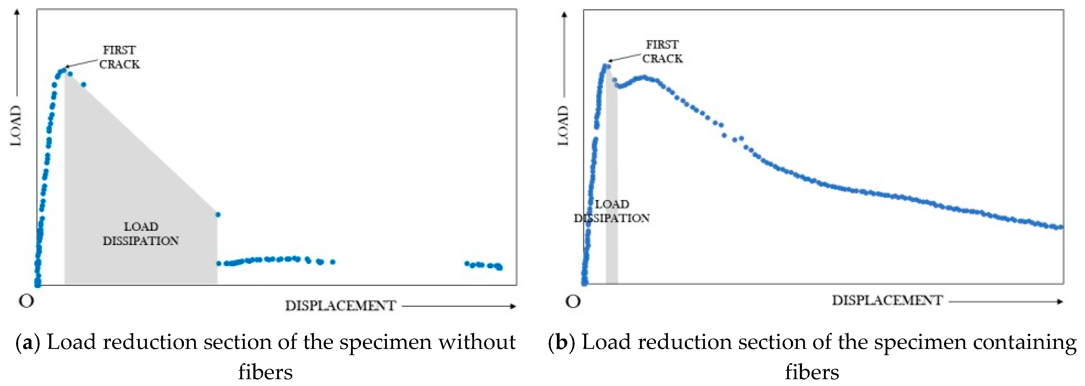
In this study, the purpose of adding fibers to concrete was to increase the flexural toughness due to the fiber’s bridging role, pullout, and fracture behavior, and to delay the rapid failure caused by the deterioration of the adhesion strength between the plastic bar and the concrete matrix. In addition, the addition of fibers can ensure the structural safety by converting brittle fracture to ductile fracture through the crack control process while transferring the load to the fiber after matrix failure in the concrete [24,25,26]. As shown in Figure 17, as the load transfer becomes smooth in the load transfer section of the fiber-reinforced concrete, the distribution of the overall load displacement graph increases, and the toughness also increases as the position of the starting point connected to the nonlinear section becomes high. In addition, as the mixing ratio of the fibers increases, the energy dissipation after the first peak load is small, and the load increase up to the second peak load is large, thus improving the ability to transfer energy to the fiber without dissipating it. This can also affect the overall toughness [27,28,29,30]. Based on the results of the previous research, the load transfer factor obtained by using the area of the load reduction section after the first peak load and the load increase section up to the second peak load is represented by Equation (1). With respect to all the specimens (F1, F2, and F3), the areas of the load reduction section after the first peak load were compared, and their effect on the overall toughness was analyzed to evaluate the flexural performance of light transparent concrete due to the addition of fibers. For the specimens containing fibers, the load transfer capacities of the specimens with plastic bars with different diameters and that of the general specimens without plastic bars were compared, and the effects of the fiber mixing ratio and the insertion of plastic bars on the toughness and ductility of the specimens were analyzed by referring to the load transfer factor Equation (1) of the previous research literature (Table 5).
: Load transfer factor (LTF); : Area of the third section (kN·mm); : Area of the second section (kN·mm).
Figure 18 shows the results of the comparison of the load dissipation and toughness. The analysis of the area of the section where the load was dissipated after the occurrence of the initial concrete matrix cracks in all the specimens revealed that the area of the load reduction section was dramatically increased in the specimens without fibers, and that the total toughness decreased as the load reduction was larger after the first peak load in the load displacement graph, showing inverse proportionality. The comparison results of the load transfer factors of the F3 specimens containing fiber revealed that the area of the load reduction section of the specimen with a 5 mm bar (S2) was the smallest, and that of the specimen into which a 10 mm bar was inserted (S2) was the largest. The area of the section with load increase (S3) was again the largest in the specimen without a plastic bar, and that (S3) of the specimen into which a 5 mm plastic bar was inserted was the smallest. The results of the load transfer factor (LTF) analysis showed that the load transfer capacity from the concrete matrix to the fiber was highest in the test specimen without a plastic bar, followed by the specimens with 5 and 10 mm plastic bars, respectively. The total toughness of the F3 specimen was increased with the addition of PVA fibers, and the insertion of the bars resulted in the reduction of the concrete matrix area, thereby reducing the concrete matrix-fiber transfer capacity.
5. Conclusions
In this study, foam and lightweight aggregates were used to achieve improved constructability and lightweight of light transparent concrete, and experiments were conducted to improve the workability to the extent that concrete can be poured tightly into the mold. As a result of the experiments, the optimum mix proportions that can reduce the unit weight of the materials and can ensure excellent flowability without material separation were derived, and the conclusions shown below were obtained based on the study results.
- The mix conditions for the realization of lightweight and for workability improvement include 45% W/C, 52.5% synthetic foaming agent, 17.5% ALA lightweight aggregate, 25% fly ash, and 0.2% PVA, and are expected to make it possible to manufacture light transparent concrete with good flowability and without material separation.
- The unit weight of the specimen fabricated with the above mix proportion was 564 kg/m3, showing an approximate 80% weight reduction compared to that of ordinary concrete (2383 kg/m3), which suggests that the work efficiency can be improved in the placement of concrete specimens and field applications.
- The mixing of PVA fibers was found to be effective in improving the consistency by preventing the aggregate from floating due to the addition of lightweight aggregate with a low specific gravity.
- The results of the load transfer factor (LTF) analysis showed that the load transfer capacity from the concrete matrix to the fiber was highest in the specimen without plastic bars, followed by the specimens with 5 and 10 mm plastic bars.
- The total toughness of light transparent concrete was increased with the addition of PVA fibers, and the insertion of bars resulted in a reduction of the concrete matrix area, thus reducing the efficiency of the load transfer between the concrete matrix and the fiber.
- The additional improvement of compressive and flexural strengths by adjusting mixing proportions or material compositions in the further research is required to apply non-structural parts of buildings, even though it showed the enhanced possibility of workability and post-cracking behaviors.
Acknowledgments
This research was supported by a Grant (NRF-2016R1C1B2009489) from the National Research Foundation of Korea (NRF).
Author Contributions
Byoungil Kim conceived and designed the experiments; Byoungil Kim and Yoon-Jung Han performed the experiments; Byoungil Kim and Yoon-Jung Han analyzed the data; Byoungil Kim and Yoon-Jung Han wrote the paper.
Conflicts of Interest
The authors declare no conflict of interest.
Abbreviations
The following abbreviations are used in this manuscript:
| ALA | Autoclaved Lightweight Concrete Aggregate |
| SFA | Synthetic Foaming Agent |
| AFA | Animality Foaming Agent |
| FA | Fine Aggregate |
| CA | Coarse Aggregate |
| LVDT | Linear Variable Differential Transformer |
| KS | Korea Standard |
| PVA | Polyvinyl Alcohol |
| LTF | Load Transfer Factor |
References
- Kim, S.C. Development of Fabrication Method for Translucent Concrete and the Material Characteristics Associated with the Use of Mineral Admixture. J. Korean Recycl. Constr. Resour. Inst. 2011, 6, 69–78. [Google Scholar]
- Lee, H.R.; Kan, H.S. A study on the fashion design with the application of nude style of architecture—Centering on the Ando Tadaos architecture. J. Korean Soc. Costume 2012, 6, 39–56. [Google Scholar]
- Kim, B.; Kim, S.W. Future oriented light emotion friendly lightweight concrete (LEFLC). Mag. Korea Concr. Inst. 2016, 28, 35–39. [Google Scholar]
- Kim, B. Light transmitting lightweight concrete with transparent plastic bar. Open Civ. Eng. J. 2017, 11, 615–626. [Google Scholar] [CrossRef]
- Wang, X.F.; Fang, C.; Kuang, W.Q.; Li, N.X.; Han, N.X.; Xing, F. Experimental investigation on the compressive strength and shrinkage of concrete with pre-wetted lightweight aggregates. Constr. Build. Mater. 2017, 155, 867–879. [Google Scholar] [CrossRef]
- Miller, N.M.; Tegrani, F.M. Mechanical properties of rubberized lightweight aggregate concrete. Constr. Build. Mater. 2017, 147, 264–271. [Google Scholar] [CrossRef]
- Kim, H.M.; Alengaram, U.J.; Jumaat, M.Z. Bond properties of lightweight concrete—A review. Constr. Build. Mater. 2016, 112, 478–496. [Google Scholar]
- Baek, J.W. A study on the Physical Characteristics of Lightweight Foamed Concrete According to Porosity. Master’s Thesis, Konkuk University, Seoul, Korea, 2013. [Google Scholar]
- Gayathri, K.S.; Anand, K.B. Performance evaluation of PVA fiber reinforced concrete. Indian Concr. J. 2017, 91, 30–36. [Google Scholar]
- Hamoush, S.; Abu-lebdeh, T.; Cummins, T. Deflection behavior of concrete beams reinforced with PVA micro-fibers. Constr. Build. Mater. 2010, 24, 2285–2293. [Google Scholar] [CrossRef]
- Liu, R.M.; Liu, W. Effect of PVA fiber on flexural properties of high performance concrete. Appl. Mech. Mater. 2013, 438–439, 262–265. [Google Scholar] [CrossRef]
- Bauml, M.F.; Wittmann, F.H. Application of PVA-fiber reinforced self-compacting concrete (ECC) for repair of concrete structures. Restor. Build. Monum. 2002, 8, 591–604. [Google Scholar]
- Huang, J.J.; Su, Q.; Zhao, W.H.; Li, T.; Zhang, X.X. Experimental study on use of lightweight foam concrete as subgrade bed filler of ballast less track. Constr. Build. Mater. 2017, 149, 911–920. [Google Scholar] [CrossRef]
- Krämer, C.; Schauerte, M.; Müller, T.; Gebhard, S.; Trettin, R. Application of reinforced three-phase-foams in UHPC Foam concrete. Constr. Build. Mater. 2017, 131, 746–757. [Google Scholar] [CrossRef]
- Standard Test Method for Concrete Slump; Korea Standards Associations: Seoul, Korea, 2017; KS F 2402.
- Foamed Concrete for Cast—In Site; Korea Standards Associations: Seoul, Korea, 2004; KS F 4039.
- Kuzielova, E.; Pach, L.; Palou, M. Effect of activated foaming agent on the foam concrete properties. Constr. Build. Mater. 2016, 125, 998–1004. [Google Scholar] [CrossRef]
- Gao, J.M.; Dong, X. Experiment study on toughness of fiber reinforced high performance light-weight aggregate concrete. Innov. Sustain. Struct. 2005, 3, 2123–2131. [Google Scholar]
- Ghrici, M.; Kenai, B.; Said-Mansour, M. Mechanical properties and durability of mortar and concrete containing natural pozzolan and limestone blended cements. Cem. Concr. Compos. 2007, 29, 542–549. [Google Scholar] [CrossRef]
- Workability and Dynamic Properties of Steel Fiber Reinforced Concrete; Institute of Construction Technology, Seoul National University of Science and Technology: Seoul, Korea, 2016.
- Standard Test Method for Compressive Strength of Concrete; Korea Standards Associations: Seoul, Korea, 2010; KS F 2405.
- Standard Test Method for Flexural Performance of Fiber Reinforced Concrete; Korea Standards Associations: Seoul, Korea, 2014; KS F 2566.
- Huang, Y.H. Evaluation of Concrete Shear Friction Strength Considering Unit-Weight. Master’s Thesis, Kyoungi University, Seoul, Korea, 2017. [Google Scholar]
- Nataraja, M.C.; Dhang, N.; Gupta, A.T. Toughness characterization of steel fiber-reinforced concrete by JSCE approach. Cem. Concr. Res. 2000, 30, 593–597. [Google Scholar] [CrossRef]
- Boulekbache, B.; Hamrat, M.; Chemrouk, M.; Amziane, S. Flexural behavior of steel fiber reinforced concrete under cyclic loading. Constr. Build. Mater. 2016, 126, 253–262. [Google Scholar] [CrossRef]
- Mertol, H.C.; Baran, E.; Bello, H.J. Flexural behavior of lightly and heavily reinforced steel fiber concrete beams. Constr. Build. Mater. 2015, 98, 185–193. [Google Scholar]
- Han, Y.J. Evaluation of Flexural Behavior Effect in the Load Transfer Zone for Steel Fiber Reinforced Concrete. Master’s Thesis, Seoul National University of Science and Technology, Seoul, Korea, 2017. [Google Scholar]
- Cao, Q.Y.; Sun, W.; Guo, L.P. The effect of organic fibers on crack resistance of concrete and applicable for secondary lining. Adv. Mater. Res. 2012, 374–377, 811–814. [Google Scholar] [CrossRef]
- Lee, J.H.; Cho, B.; Choi, E. Flexural capacity of fiber reinforced concrete with a consideration of concrete strength and fiber content. Constr. Build. Mater. 2017, 138, 222–231. [Google Scholar] [CrossRef]
- Al-Osta, M.A.; Isa, M.N.; Baluch, M.H.; Rahman, M.K. Flexural behavior of reinforced concrete beams strengthened with ultra-high performance fiber reinforced concrete. Constr. Build. Mater. 2017, 134, 279–296. [Google Scholar] [CrossRef]
Figure 1.
Detailed images of plastic bars.
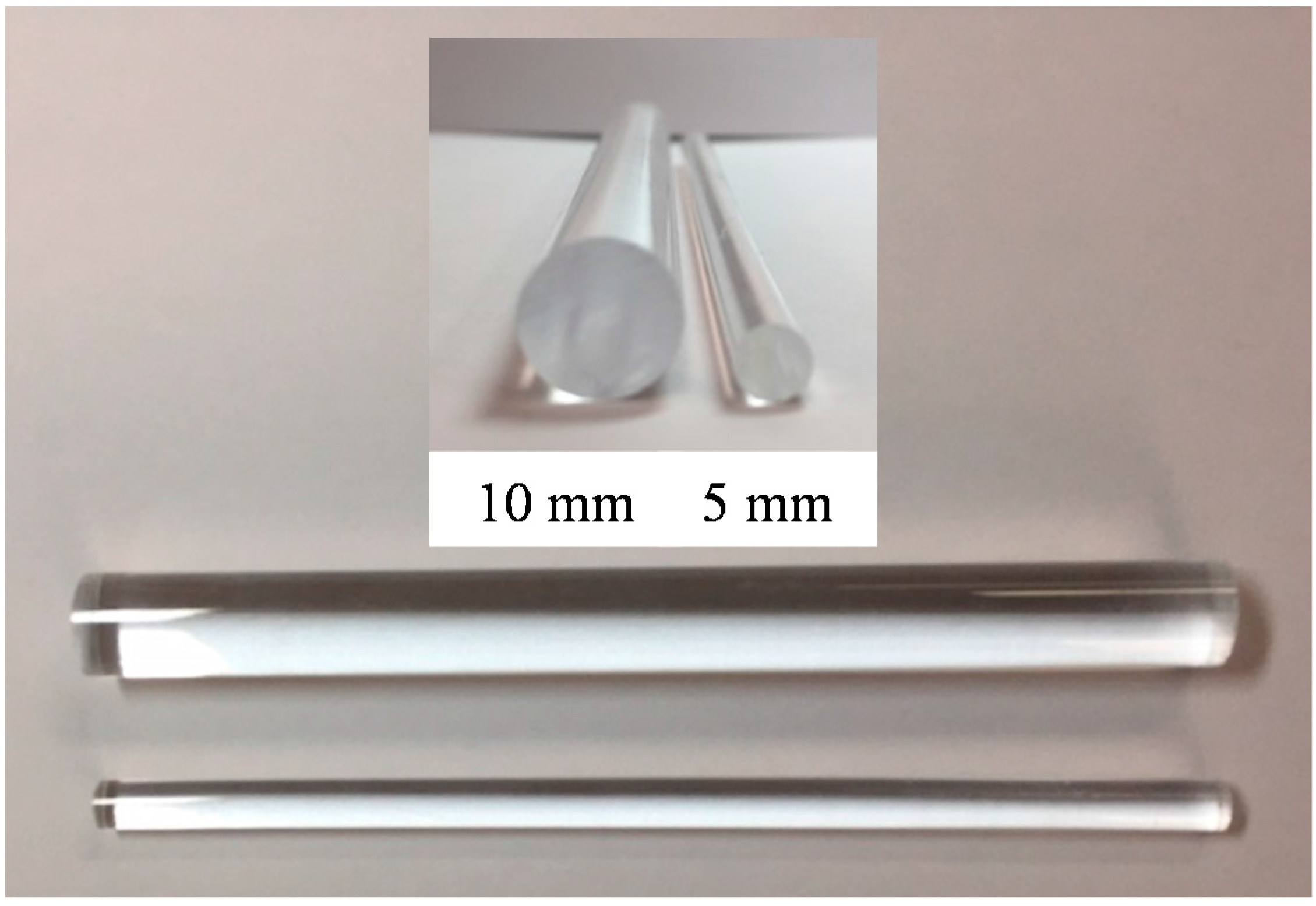
Figure 2.
Detailed image of PVA (Polyvinyl Alcohol) Fiber.
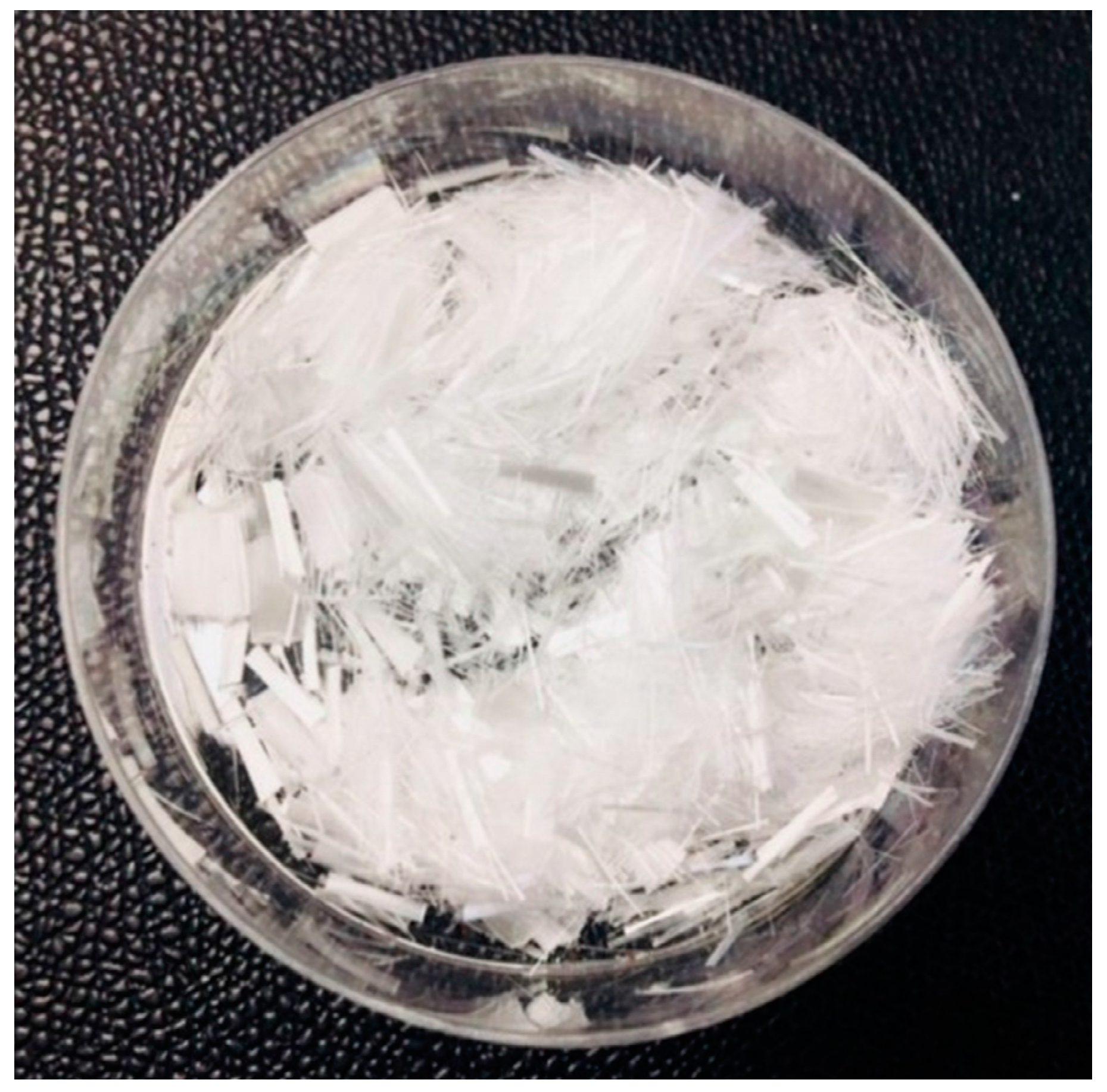
Figure 3.
Research flow chart.

Figure 4.
Flow test results according to foaming agents and water-cement ratios.
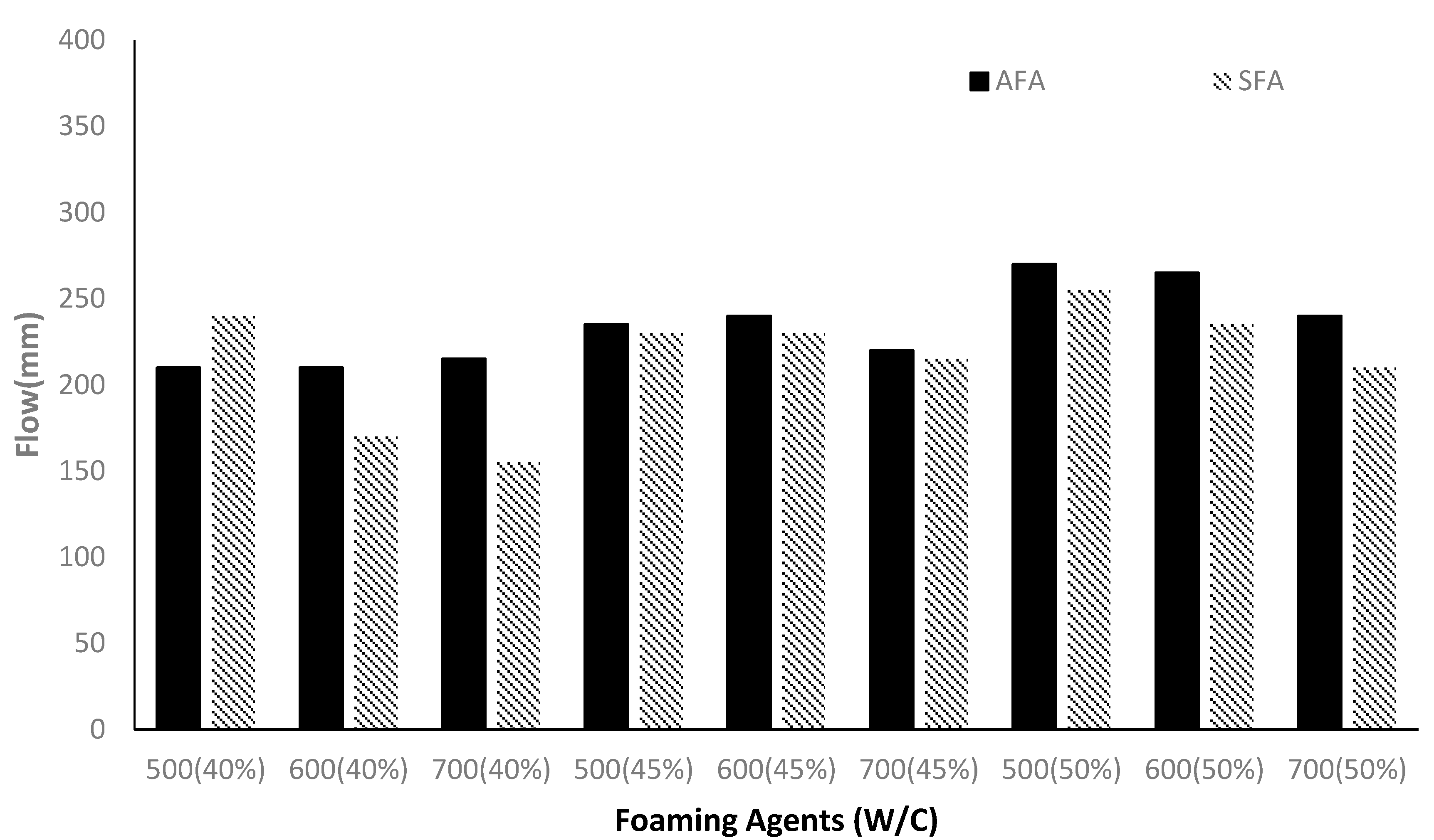
Figure 5.
Flow test results according to lightweight aggregates and fiber mixing ratios.
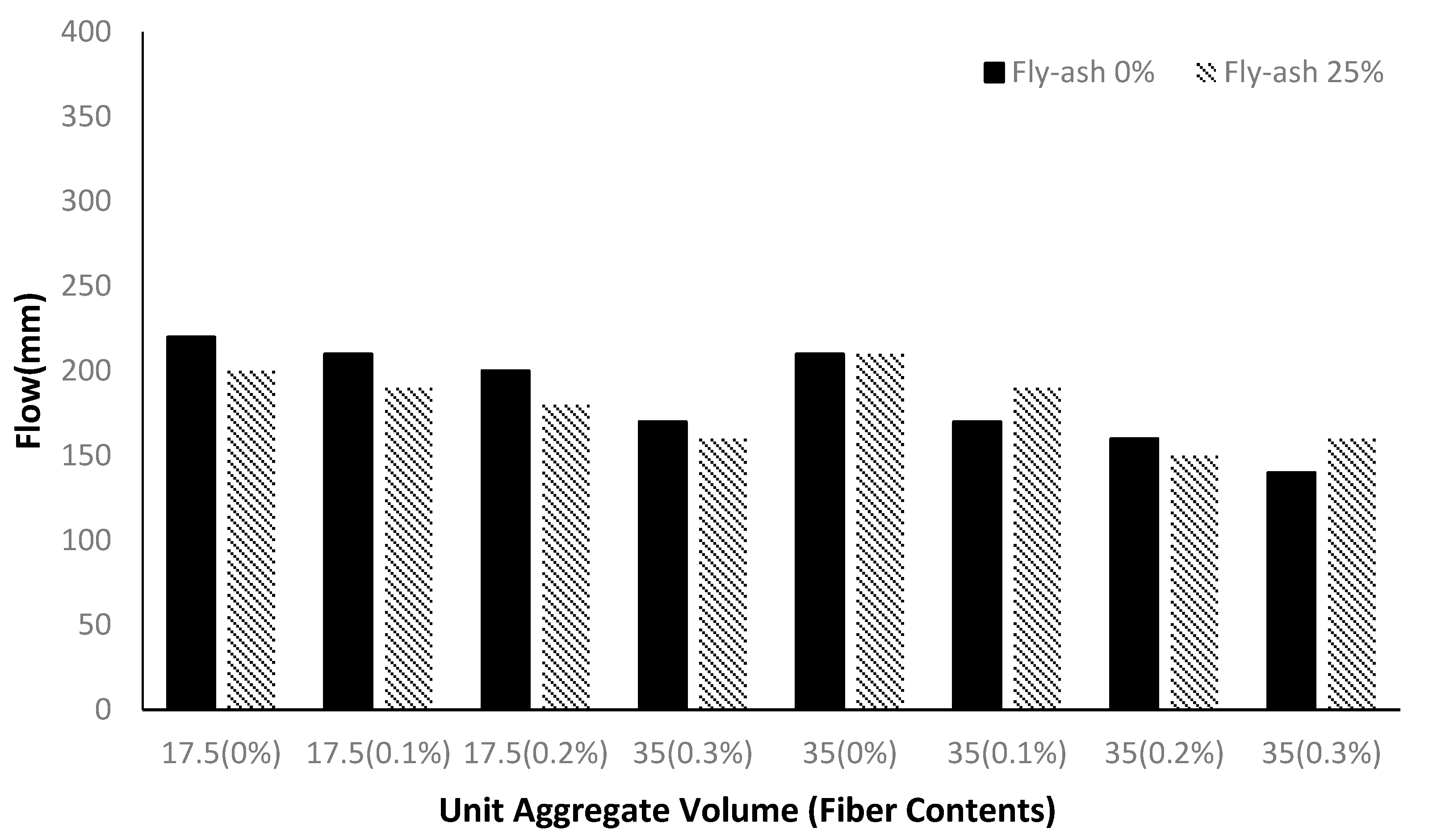
Figure 6.
Economical efficiency and light transmittance according to changes in the number of plastic bars.
Figure 6.
Economical efficiency and light transmittance according to changes in the number of plastic bars.
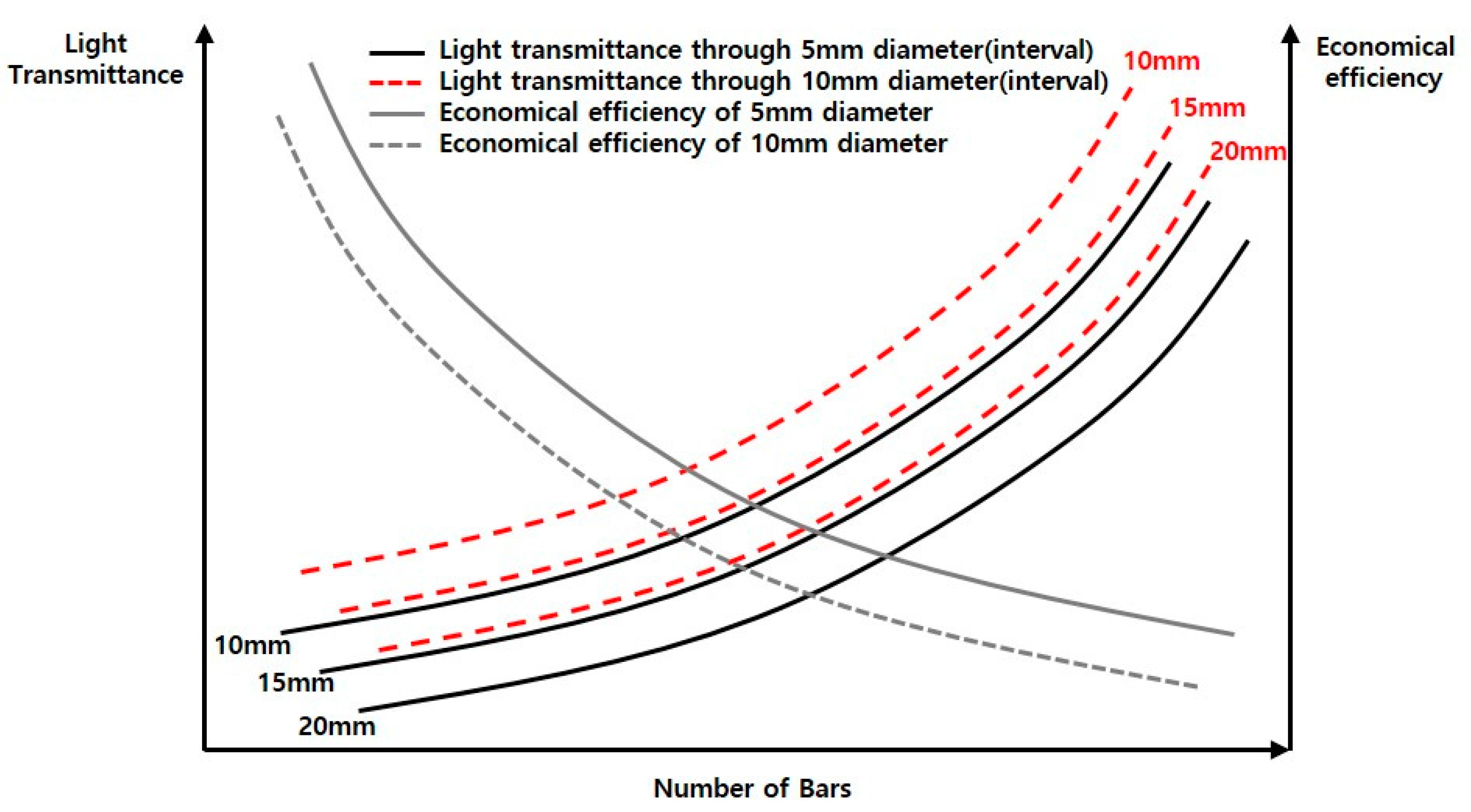
Figure 7.
Production process for light transparent concrete.
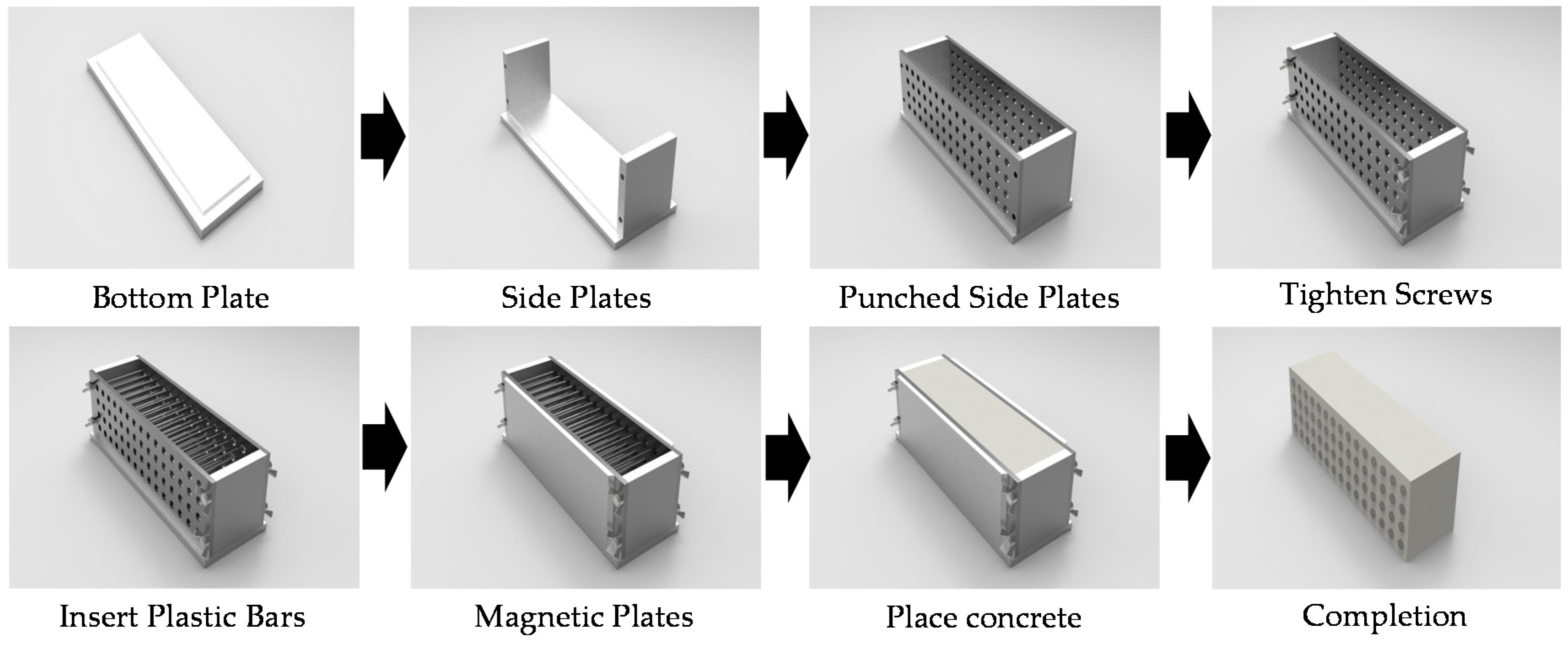
Figure 8.
Light transmittance according to the diameters and intervals between bars.

Figure 9.
Test of flexural behavior characteristics.

Figure 10.
Compressive strength.
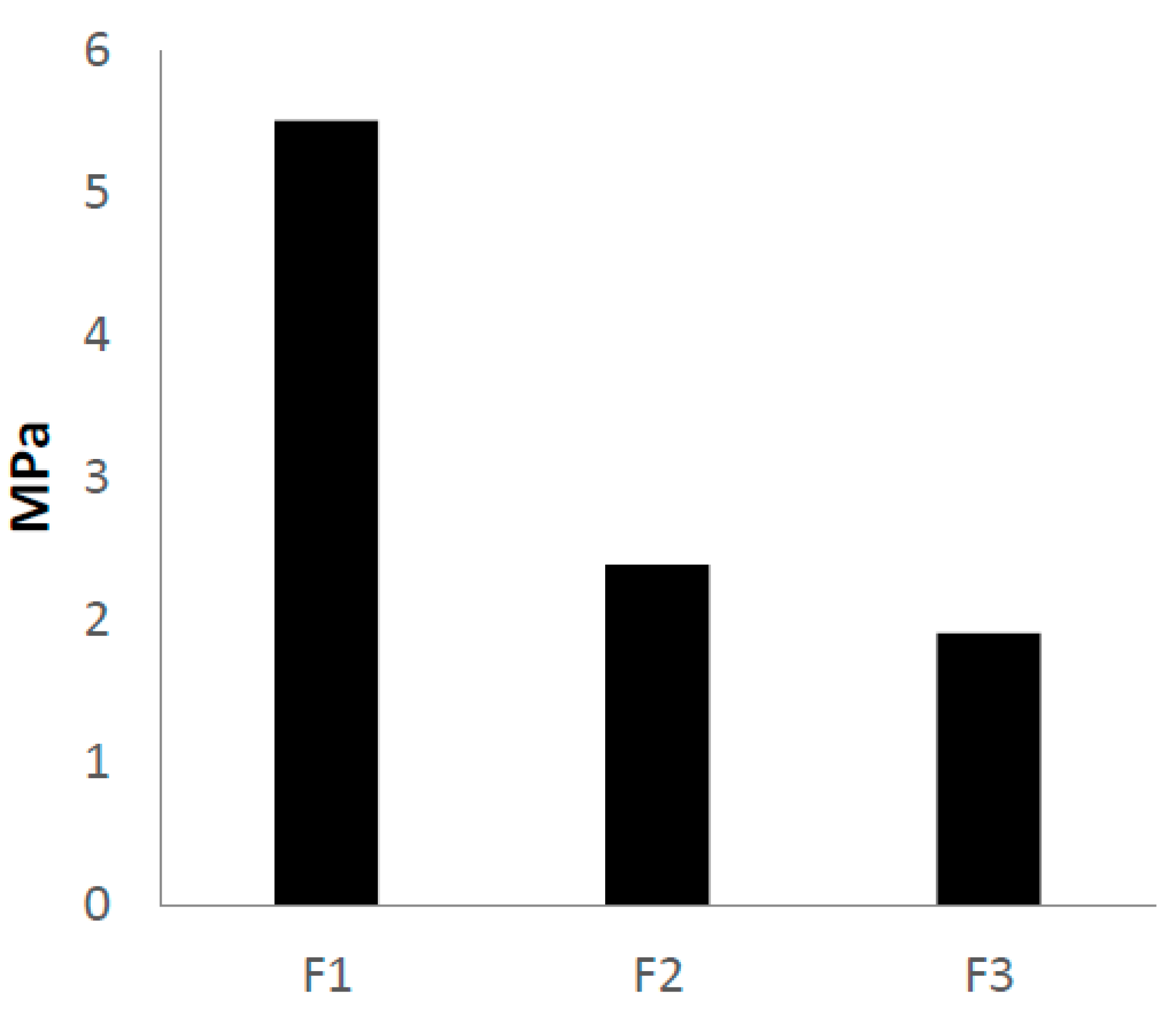
Figure 11.
Unit volume weight.
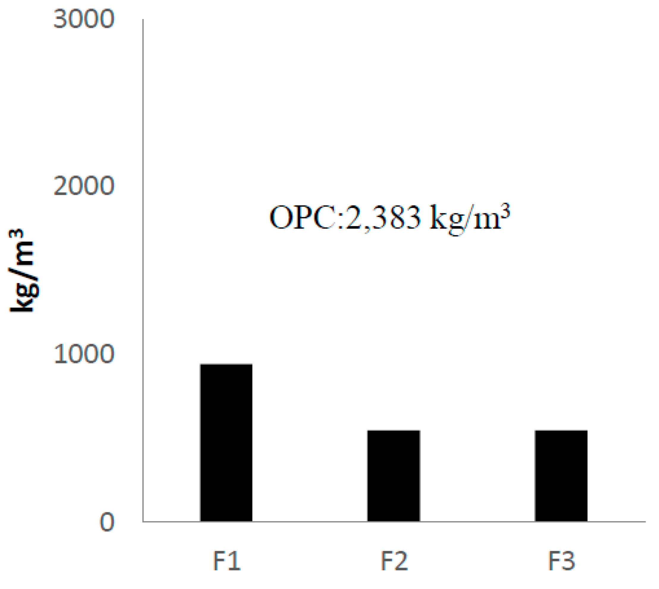
Figure 12.
Flexural behavior characteristics (F1).

Figure 13.
Flexural behavior characteristics (F2).
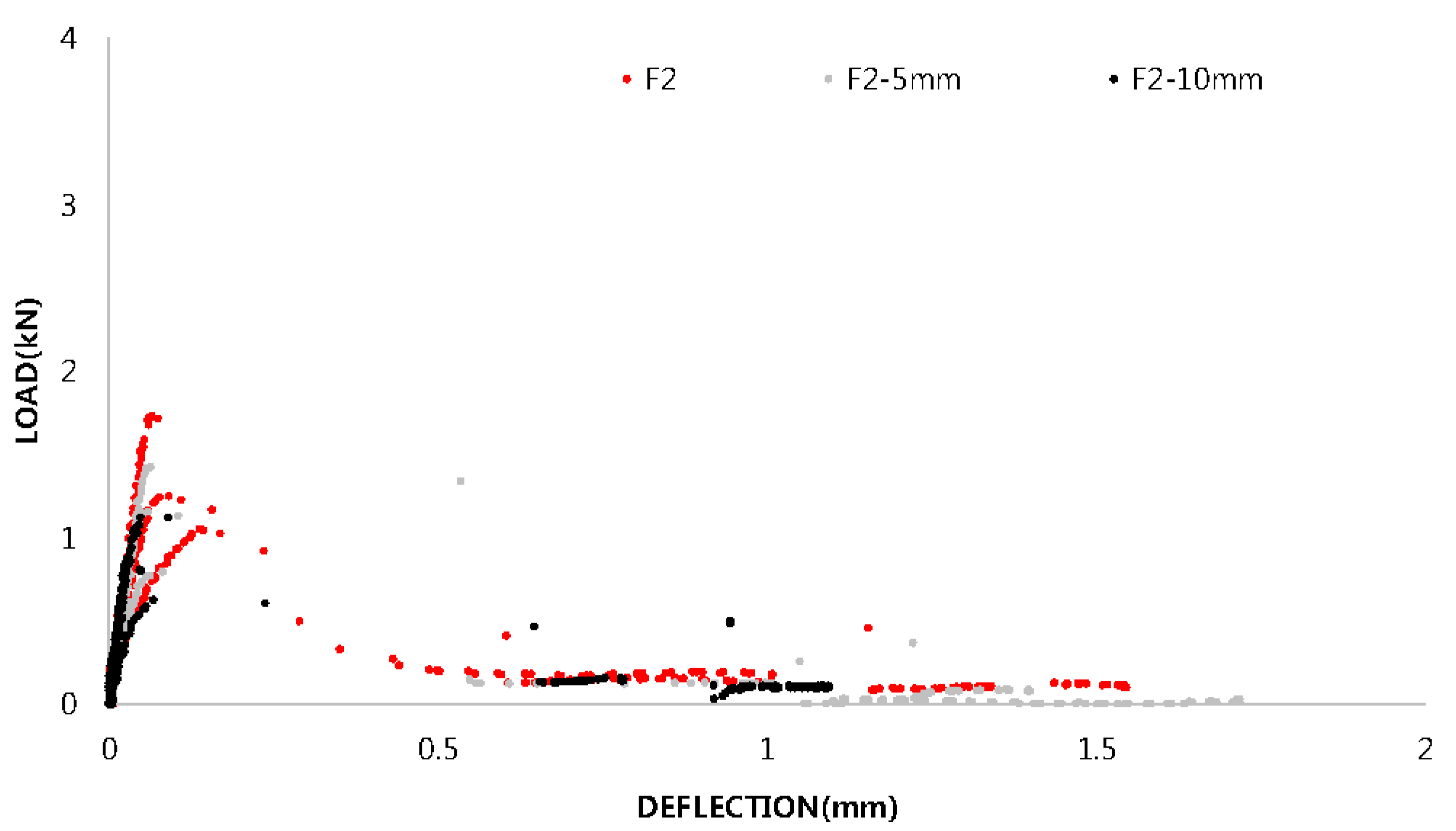
Figure 14.
Flexural behavior characteristics (F3).
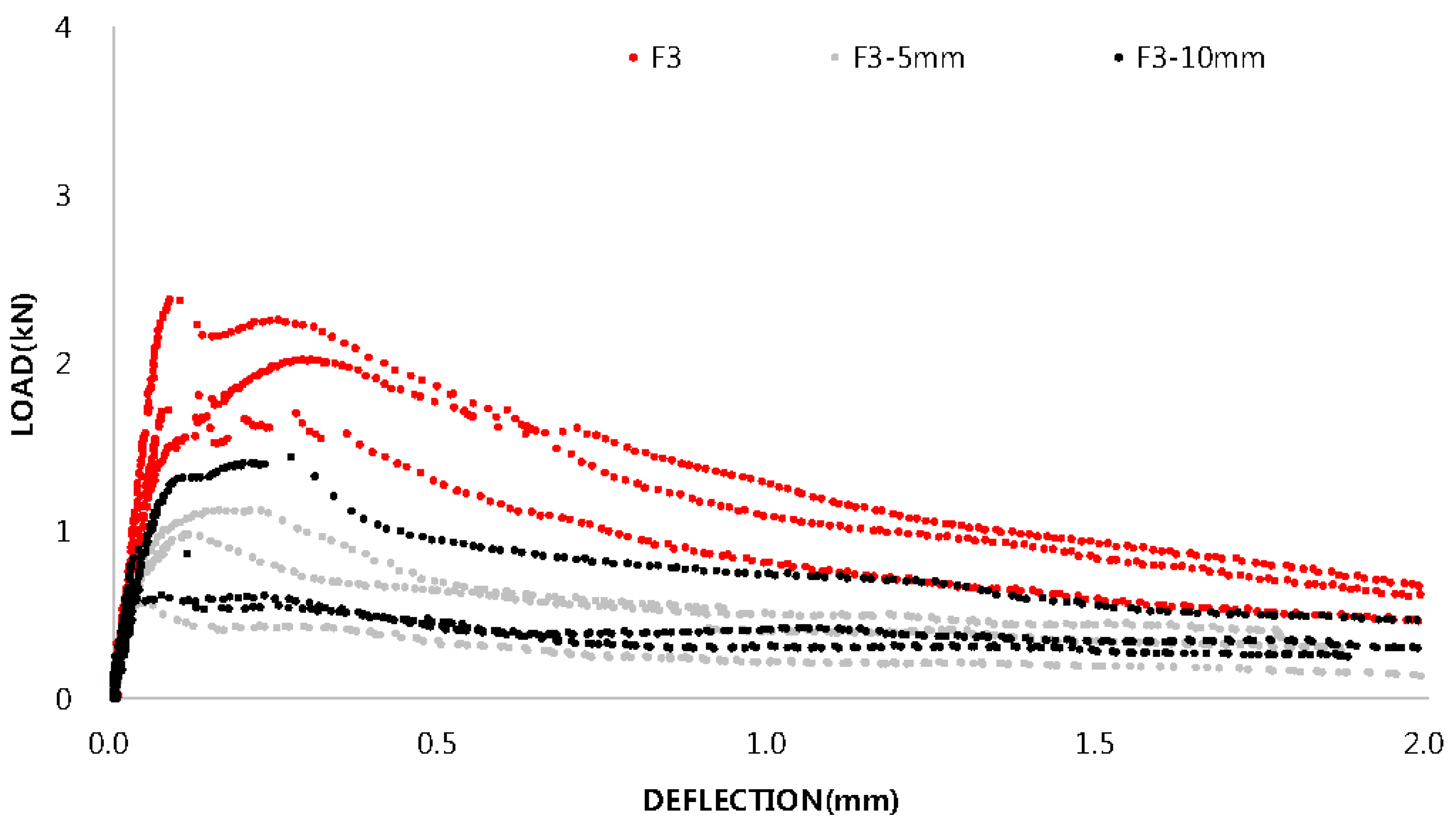
Figure 15.
Comparison between the first peak load and the toughness.

Figure 16.
Cross sections of flexural test specimens.
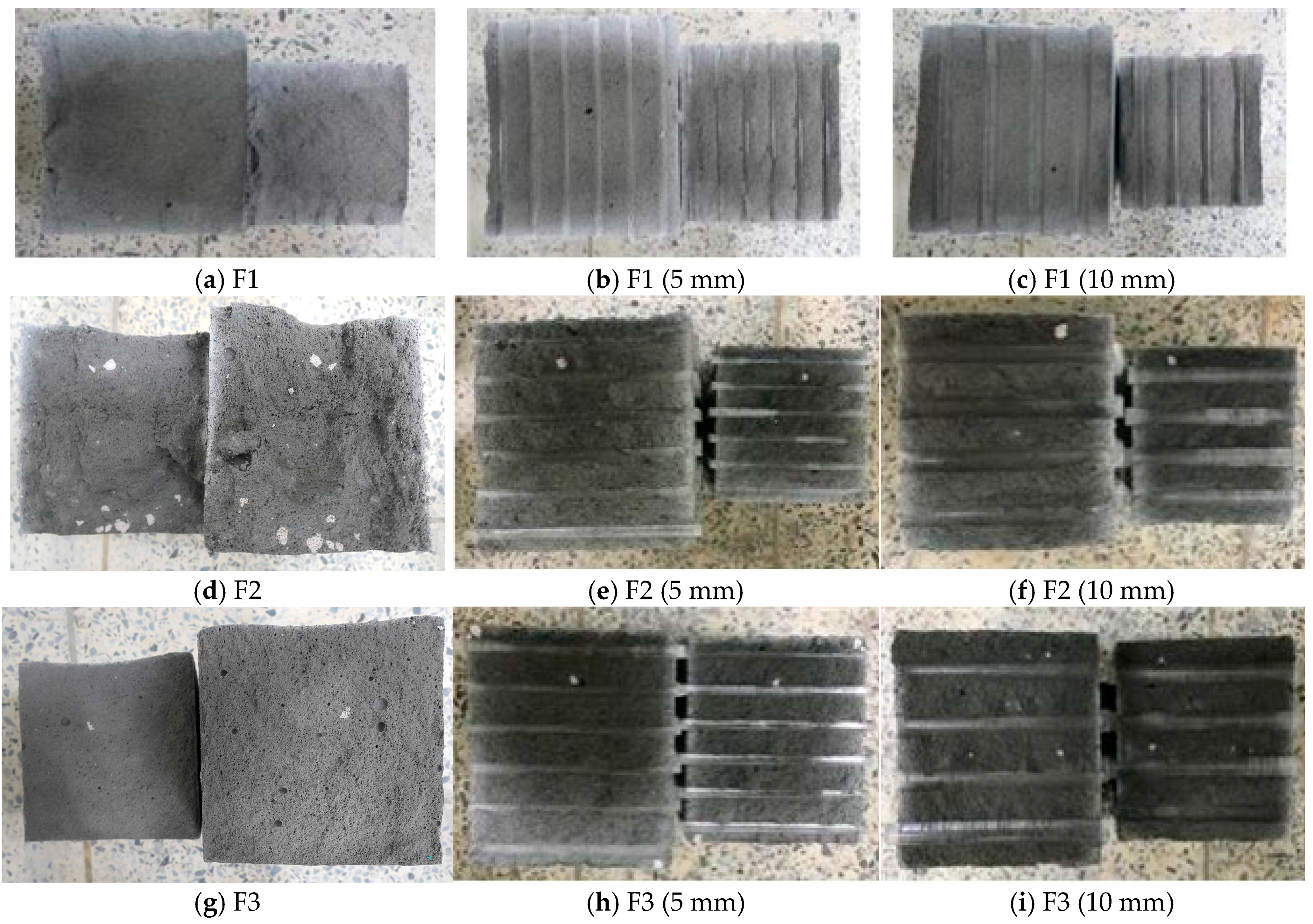
Figure 17.
Load reduction sections.

Figure 18.
Comparison between toughness and load dissipation.


Table 1.
Physical Properties of the aggregate.
| Category | Lightweight Aggregate |
|---|---|
| Symbol | ALA (Autoclaved Lightweight Concrete Aggregate) |
| Specification | Crushed foam concrete |
| Specific gravity (kg/m3) | 0.60 |
| Maximum diameter (mm) | 8 |
| Photo | 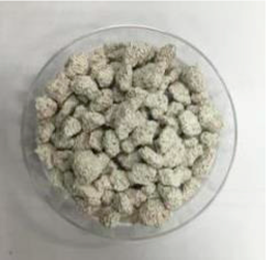 |
Table 2.
Experimental design for each step.
| Step | Experimental Content |
|---|---|
| Step 1 | Slump test according to the types of foaming agents, input amounts, and water-cement ratio changes |
| Step 2 | Slump test according to the input amounts of lightweight aggregates and presence of fly ash |
| Step 3 | Test of basic properties of specimens using the derived mix proportions (compressive strength, flexural strength) |
| Step 4 | Analysis of flexural behavior characteristics and analysis on the load transfer sections of light transparent concrete reinforced with fibers |
Table 3.
Mix design. ALA: autoclaved lightweight concrete aggregate; SFA: synthetic foaming agent; AFA: animality foaming agent.
Table 3.
Mix design. ALA: autoclaved lightweight concrete aggregate; SFA: synthetic foaming agent; AFA: animality foaming agent.
| No. | Specimen | W/C (%) | Unit Weight (kg/m3) | Foam (L/m3) | Fiber Volume (%) | Super Plasticizer (kg/m3) | |||||
|---|---|---|---|---|---|---|---|---|---|---|---|
| Water | Binder | Cement | Fly Ash | ALA | SFA | AFA | |||||
| 1 | SFA 50 (40%) | 40 | 278 | 222 | 222 | - | - | 500 | - | - | 1.40 |
| 2 | SFA 60 (40%) | 222 | 178 | 178 | 600 | 1.12 | |||||
| 3 | SFA 70 (40%) | 167 | 133 | 133 | 700 | 0.84 | |||||
| 4 | SFA 50 (45%) | 45 | 294 | 206 | 206 | 500 | 1.30 | ||||
| 5 | SFA 60 (45%) | 235 | 165 | 165 | 600 | 1.04 | |||||
| 6 | SFA 70 (45%) | 176 | 124 | 124 | 700 | 0.78 | |||||
| 7 | SFA 50 (50%) | 50 | 306 | 194 | 194 | 500 | 1.22 | ||||
| 8 | SFA 60 (50%) | 244 | 156 | 156 | 600 | 0.98 | |||||
| 9 | SFA 70 (50%) | 184 | 116 | 116 | 700 | 0.73 | |||||
| 10 | AFA 50 (40%) | 40 | 278 | 222 | 222 | - | - | - | 500 | - | 1.40 |
| 11 | AFA 60 (40%) | 222 | 178 | 178 | 600 | 1.12 | |||||
| 12 | AFA 70 (40%) | 167 | 133 | 133 | 700 | 0.84 | |||||
| 13 | AFA 50 (45%) | 45 | 294 | 206 | 206 | 500 | 1.30 | ||||
| 14 | AFA 60 (45%) | 235 | 165 | 165 | 600 | 1.04 | |||||
| 15 | AFA 70 (45%) | 176 | 124 | 124 | 700 | 0.78 | |||||
| 16 | AFA 50 (50%) | 50 | 306 | 194 | 194 | 500 | 1.22 | ||||
| 17 | AFA 60 (50%) | 244 | 156 | 156 | 600 | 0.98 | |||||
| 18 | AFA 70 (50%) | 184 | 116 | 116 | 700 | 0.73 | |||||
| 19 | LWA25 | 45 | 176 | 124 | 124 | 0 | 175 | 525 | - | 0 | 0.78 |
| 20 | LWA25 (0.1%) | 0.1 | |||||||||
| 21 | LWA25 (0.2%) | 0.2 | |||||||||
| 22 | LWA25 (0.3%) | 0.3 | |||||||||
| 23 | LWA50 | 350 | 350 | - | 0 | ||||||
| 24 | LWA50 (0.1%) | 0.1 | |||||||||
| 25 | LWA50 (0.2%) | 0.2 | |||||||||
| 26 | LWA50 (0.3%) | 0.3 | |||||||||
| 27 | FALWA25 | 170 | 130 | 98 | 33 | 175 | 525 | - | 0 | 0.76 | |
| 28 | FALWA25 (0.1%) | 0.1 | |||||||||
| 29 | FALWA25 (0.2%) | 0.2 | |||||||||
| 30 | FALWA25 (0.3%) | 0.3 | |||||||||
| 31 | FALWA50 | 350 | 350 | - | 0 | ||||||
| 32 | FALWA50 (0.1%) | 0.1 | |||||||||
| 33 | FALWA50 (0.2%) | 0.2 | |||||||||
| 34 | FALWA50 (0.3%) | 0.3 | |||||||||
Table 4.
Proportions of mix for the test of basic properties.
| Type | Specimen | W/C Ratio (%) | Water (kg/m3) | Binder (kg/m3) | Cement (kg/m3) | Fly Ash (kg/m3) | Lightweight Aggregate (kg/m3) | Foam (L/m3) | Fiber Contents (%) | Bar Space (mm) | Bar Diameter (mm) |
|---|---|---|---|---|---|---|---|---|---|---|---|
| Foam | F1 | 45 | 294 | 206 | 206 | - | - | 500 | - | 10 | 5, 10 |
| Fly ash + Foam + Lightweight Aggregate | F2 | 45 | 170 | 131 | 98 | 33 | 175 | 525 | - | 10 | 5, 10 |
| Fly ash + Foam + Lightweight Aggregate + Fiber | F3 | 45 | 170 | 131 | 98 | 33 | 175 | 525 | 2 | 10 | 5, 10 |
Table 5.
F3 Analysis of the load transfer capacities of specimens.
| Bar Diameter (mm) | Specimen | Load Dissipation Area (kN * mm) | Load Reduction Area Average | Load Re-Raised Area (kN * mm) | Section Where Load Increases Average | Load Transfer Factor |
|---|---|---|---|---|---|---|
| No bars | 1 | 0.16 | 0.07 | 0.25 | 0.30 | 1.57 |
| 2 | 0.05 | 0.21 | 4.19 | |||
| 3 | 0 | 0.44 | ∞ | |||
| 5 mm | 1 | 0 | 0.01 | 0 | 0.09 | ∞ |
| 2 | 0.04 | 0.07 | 2 | |||
| 3 | 0 | 0.19 | ∞ | |||
| 10 mm | 1 | 0.46 | 0.18 | 0.26 | 0.13 | 0.56 |
| 2 | 0.06 | 0.05 | 0.78 | |||
| 3 | 0.02 | 0.07 | 4.03 |
© 2018 by the author. Licensee MDPI, Basel, Switzerland. This article is an open access article distributed under the terms and conditions of the Creative Commons Attribution (CC BY) license (http://creativecommons.org/licenses/by/4.0/).
Share and Cite
MDPI and ACS Style
Kim, B.; Han, Y.-J. Flexural Performance of Transparent Plastic Bar Reinforced Concrete. Appl. Sci. 2018, 8, 325. https://doi.org/10.3390/app8030325
AMA Style
Kim B, Han Y-J. Flexural Performance of Transparent Plastic Bar Reinforced Concrete. Applied Sciences. 2018; 8(3):325. https://doi.org/10.3390/app8030325
Chicago/Turabian StyleKim, Byoungil, and Yoon-Jung Han. 2018. "Flexural Performance of Transparent Plastic Bar Reinforced Concrete" Applied Sciences 8, no. 3: 325. https://doi.org/10.3390/app8030325
Note that from the first issue of 2016, this journal uses article numbers instead of page numbers. See further details here.