Surface Decorated Zn0.15Cd0.85S Nanoflowers with P25 for Enhanced Visible Light Driven Photocatalytic Degradation of Rh-B and Stability


State Key Laboratory of Advanced Technology for Materials Synthesis and Processing, School of Materials Science and Engineering, Wuhan University of Technology, Wuhan 430070, China
*
Author to whom correspondence should be addressed.
Appl. Sci. 2018, 8(3), 327; https://doi.org/10.3390/app8030327
Submission received: 22 January 2018
/
Revised: 10 February 2018
/
Accepted: 17 February 2018
/
Published: 26 February 2018
(This article belongs to the Section Chemical and Molecular Sciences)
Abstract
:Featured Application
P25/Zn0.15Cd0.85S nanocomposite possesses a great potential to be a green catalyst for the photolytic degradation of hazardous dyes due to its low cost, efficient reactivity and high stability. The prepared catalyst may further be used for the degradation of organic compound and toxic heavy metals.
Abstract
Decoration of Zn0.15Cd0.85S nanoflowers with P25 for forming P25/Zn0.15Cd0.85S nanocomposite has been successfully synthesized with fine crystallinity by one-step low temperature hydrothermal method. Photocatalytic efficiency of the as-prepared P25/Zn0.15Cd0.85S for the degradation of Rh-B is evaluated under the visible light irradiation. The synthesized composite is completely characterized with XRD, FESEM, TEM, BET, and UV-vis DRS. TEM observations reveal that P25 is closely deposited on the Zn0.15Cd0.85S nanoflowers with maintaining its nanoflower morphology. The photocatalytic activity of the as-obtained photocatalyst shows that the P25/Zn0.15Cd0.85S exhibits very high catalytic activity for degradation of Rh-B under visible light irradiation due to an increasing of the active sites and enhancing the catalyst stability because of the minimum recombination of the photo-induced electrons and holes. Moreover, it is found that the nanocomposite retains its photocatalytic activity even after four cycles. In addition, to explain the mechanism of degradation, scavengers are used to confirm the reactive species. Photo-generated holes and ●OH play a significant role in the visible light of P25/Zn0.15Cd0.85S nanocomposite induced degradation system, but electrons play the most important role.
1. Introduction
The environmental pollution situation has changed from bad to worse in recent decades, which is obviously due to the rapid growth of urbanization and industrialization. Nanostructured semiconductor photocatalysts have an essential role in energy and environmental applications, such as water splitting and organic pollutants degradation [1,2,3]. Cadmium sulfide (CdS) has been given tremendous attention among various photocatalysts due to its unique characteristics, such as its catalytic active nature under visible light and suitable band gap (2.4 eV), which may be employed for the production of chemical energy from solar energy under sun light irradiation [4]. Due to these functional properties CdS has a great potential to be used in numerous applications, such as electronics, ceramics, optics, and catalysis [5,6]. However, CdS, like other metal sulfides photocatalysts, is unstable under light irradiation, a phenomenon known as photocorrosion or photodissolution, where S2− in CdS is oxidized by the photo-generated holes accompanied with elution of Cd2+ [7]. The photocatalytic activity and stability of CdS can be improved by enhancing the separation capacity of the photogenerated electron-hole pairs. Therefore, much effort has been directed at restraining the photocatalytic instability of CdS. This was mainly achieved either through metal doping [8,9], or by coupling CdS with a semiconductor having suitable conduction and valance band potentials, such as PdS, TiO2, ZnO [10], ZnS, LaMnO3, and ZrO2 [11]. Zn doped CdS solid solutions with different morphologies were reported [12,13,14], which have achieved greater photocatalytic efficiency than pure CdS for dye degradation. The Zn 3d incorporation into CdS crystal structure can enlarge the absorption edge and may lead to new properties and applications in the photocatalysis [15,16,17,18,19,20,21]. On the other hand, most reports are mainly focused on decorating or coupling CdS with semiconductors, such as TiO2, to improve the photocatalytic performance of CdS [22,23,24]. Indeed, such modifications have resulted in the increased photocatalytic activities due to the efficient separation of photo-induced electrons and holes occurring during the photocatalysis process [25,26]. Herein, we report the synthesis of P25/Zn0.15Cd0.85S nanocomposite by one-step low temperature hydrothermal method, as well as its photocatalytic studies for the degradation of Rh-B. The P25/Zn0.15Cd0.85S nanocomposite is an efficient adsorbent and it shows high photocatalytic activity and stability in the organic dyes degradation, e.g., (Rh-B). The outstanding performance suggests that the flower-like nanostructure of Zn0.15Cd0.85S could be useful as sites for the depositing small amounts of P25 in the petals of the P25/Zn0.15Cd0.85S nanocomposite, which facilitates the charge transfer process that is responsible for the high photocatalytic activity and stability of CdS nanoparticles.
2. Materials and Methods
2.1. Materials
Cadmium acetate (Cd(CH3COOH)2·2H2O), thiourea ((NH2)2CS), zinc acetate (Zn(CH3COOH)2 2H2O), titanium dioxide (Degussa P25), rhodamine B, polyethylene glycol (PEG 400), and ethanol were purchased from Guoyao Chemical Company (Beijing, China). All of the reagents were of analytical grade and were used as received. Distilled water was used for all of the experiments.
2.2. Hydrothermal Synthesis of Pure CdS Nanoparticles and Zn0.15Cd0.85S Nanoflowers
CdS nanoparticles and Zn0.15Cd0.85S nanoflowers were synthesized via a facile one-step hydrothermal method. Typically, for pure CdS, source materials containing 7.1 mM cadmium acetate (Cd(CH3COOH)2 2H2O) and 7.2 mM thiourea ((NH2)2CS) were dissolved in 80 mL distilled water and stirred for 10 min at room temperature. To prepare Zn0.15Cd0.85S nanoflowers, stoichiometric amounts of cadmium acetate, thiourea, and zinc acetate were firstly dissolved in 80 mL distilled water with stirring for 10 min at room temperature. Then, the solution was transferred into a 100 mL Teflon-lined stainless steel autoclave at 160 °C for 12 h. After cooling to room temperature, the precipitate was filtered off, washed several times with ethanol and deionized water, and then dried at 80 °C for 8 h.
2.3. Hydrothermal Synthesis of P25/Zn0.15Cd0.85S Nanocomposite
P25/Zn0.15Cd0.85S nanocomposite was prepared by a similar method. Firstly, a solution containing the same amounts of cadmium acetate, thiourea, and zinc acetate, which was used to prepare Zn0.15Cd0.85S nanoflowers in 80 mL distilled water with stirring for 10 min at room temperature. Then, 30 mL of polyethylene glycol was stirred for 10 min with P25 and then dropwisely added to the previously prepared solution of Zn0.15Cd0.85S. Afterwards, the solution was stirred for 30 min and then transferred into a 120 mL Teflon-lined stainless steel autoclave at 180 °C for 18 h. The product was collected and washed five times with ethanol and distilled water, and then dried at 70 °C for 24 h. To prepare different samples, molar ratio of P25/Cd had been tuned during the synthesis.
2.4. Photocatalytic Degradation of Rhodamine B (Rh-B) under Visible Light
The photocatalytic dye degradation efficiency of the as-prepared catalysts was evaluated under visible light irradiation at room temperature for Rh-B. A 350 W Xenon lamp (Lap Pu, XQ) was used as a light source and cut off filter with 3 mm thickness was used, the separation distance between the light source and the reaction mixture was kept 10 cm. A certain amount of the prepared photocatalyst was added to the Rh-B solution (100 mL, 30 mg L−1), each. Prior to the irradiation, the solution was stirred for 30 min in dark to establish adsorption/desorption equilibrium between the photocatalysts and the dye. Then, the solution was exposed to light irradiation with continuous stirring and 2 mL of the sample was taken out after each 30 min till 3 h. The photocatalyst was separated from the solution by centrifuging at 4000 rpm for 5 min. The Rh-B concentration was determined from absorption spectra (400 to 700 nm) using a UV-vis spectrophotometer at maximum absorption peak value of each sample approximately at 553 nm. Scavengers were added for the determination of reactive species and an explanation of the possible reaction mechanism that is involved in the photo-degradation of the Rh-B by P25/Zn0.15Cd0.85S nanocomposite 1-5.
2.5. Characterization
X-ray diffraction spectra were obtained from a Rigaku diffractometer with Cu-Kα radiation (λ = 1.5418 Å) in the scan range of 10°–70°. The morphologies and structures of the samples were characterized by scanning electron microscopy (FESEM, JEOL, JSM-7800F, Japan) and high-resolution transmission electron microscopy (HRTEM, JEOL, JEM-2100, Japan). The Bruauer−Emmett−Teller (BET) surface area of the samples was determined by a high speed automated area. Diffuse reflectance spectra (DRS) of powders and the absorbance measurements for photocatalysis experiments were obtained by using a UV-vis spectrophotometer (Shimadzu, UV-2550, Kyoto, Japan). The X-ray photoelectron spectrum (XPS, Quantum 2000, PHI, Eden Prairie, MN, USA) measurements were carried out with a monochromatic Al Kα source and charge neutralizer.
3. Results and Discussion
3.1. Structure, Morphology, Surface and Spectroscopic Studies
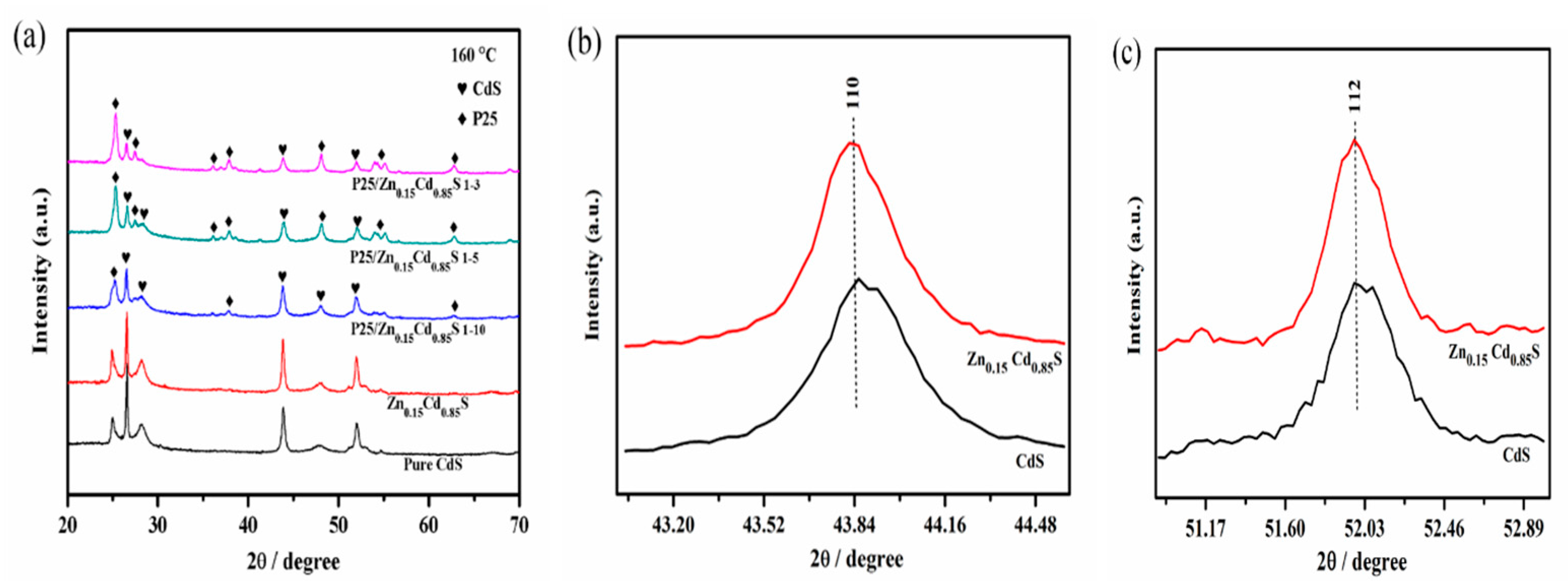
X-ray diffraction (XRD) patterns were collected to study the crystal phase and the crystallinity of the prepared nanomaterials. Figure 1 displays a comparison of the XRD results for the pure CdS nanoparticles, Zn0.15Cd0.85S nanoflowers, and P25/Zn0.15Cd0.85S nanocomposite. The refraction peaks of pure CdS and Zn0.15Cd0.85S nanoflowers samples are well-indexed to the hexagonal CdS phase (JCPDS No.41-1049), while for Zn0.15Cd0.85S nanoflowers, there is no peak for Zn, indicating that it is not a mixture of Zn and CdS phases. It can be observed that P25/Zn0.15Cd0.85S nanocomposite consists of two kinds of crystal phases, indicating that it is a mixture of CdS and TiO2 phases (P25). Diffraction peaks at 2θ of 25.3°, 37.8°, 48.05°, 55.0°, and 62.7° are attributed to anatase TiO2 (JCPDS card No. 21-1272). However, when the molar ratio of P25 increases, two additional peaks appear at 27.4° and 36.1°, which can be attributed to the rutile phase of TiO2 (JCPDS card No. 65-0191), as shown in P25/Zn0.15Cd0.85S nanocomposite 1-5 and 1-3 with P25:Cd = 1:5 and 1:3, respectively. Doping CdS with Zn causes a slight shift in the peaks from (110) and (112) crystals planes for Zn0.15Cd0.85S toward lower diffraction angles, as shown in Figure 1b,c. Obviously, Zn2+ ions are incorporated into the CdS crystal lattice or entered its interstitial sites as the ionic radius of the substitute Zn2+ (rZn2+ = 0.74 Å) is smaller than that of Cd2+ (rCd2+ = 0.97 Å) [27].
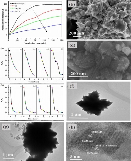
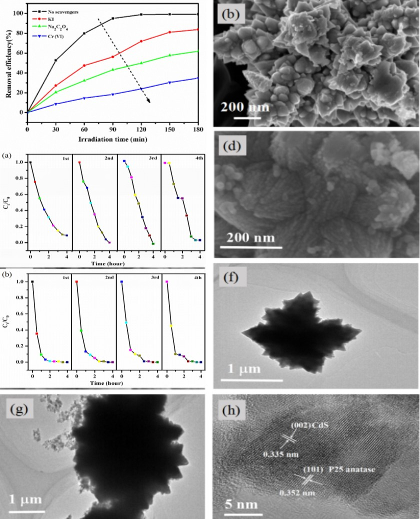
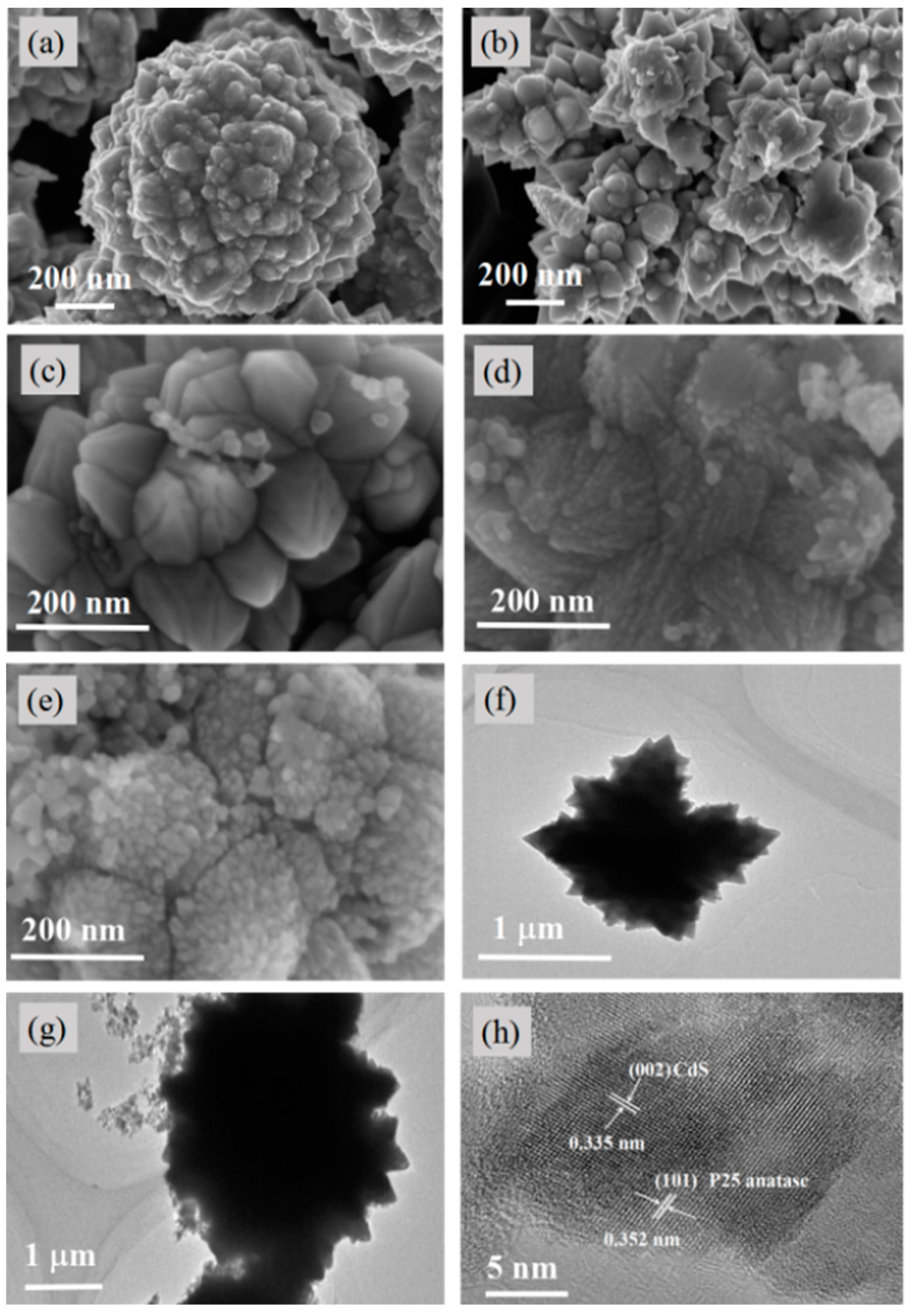
The morphological features of CdS nanoparticles, Zn0.15Cd0.85S nanoflowers, and P25/Zn0.15Cd0.85S nanocomposite were studied using FESEM and HRTEM micrographs. Figure 2a depicts the SEM image of one particle of pure CdS with agglomeration in different sizes, the diameter was about 1 μm. In the case of Zn0.15Cd0.85S, the particle of CdS changes to flower-like morphology with around 1.5 μm diameter of an entire flower, which composes of some petals, each petal contains many small particles existing outside of the main petal after doping by Zn ions to form the Zn0.15Cd0.85S nanoflowers shown in Figure 2b, this morphology may enhance the absorption properties on the surface [28]. Figure 2c–e show SEM images of P25/Zn0.15Cd0.85S nanocomposite with different P25:Cd ratios of 1:10, 1:5 and 1:3, respectively. It reveals that the petals of flower-like structure will disappear when molar ratio of P25 increases. This is due to the fact that the P25 will deposit inside the petals and the excess particles of P25 will be deposited on the surface of Zn0.15Cd0.85S nanoflowers, leading to the complete coverage of the petals and the disappearance of the flower-like structure. The flower-like surfaces could provide nucleating sites for P25 nanoparticles resulting in the formation of P25/Zn0.15Cd0.85S nanocomposite. P25 has higher BET surface area than pure CdS and Zn0.15Cd0.85S nanoflowers, thus it might cover the surface of Zn0.15Cd0.85S nanoflowers. The surface area of CdS nanoparticles was originally 0.26 m2 g−1 and it increases slightly to 0.63 m2 g−1 after the doping with zinc ions, then increases to 7.50, 21.4, and 37.8 m2g−1 respectively, after decorating with P25, as shown in Table 1. One can observe that the Zn0.15Cd0.85S nanoflowers with an approximate diameter around 1.5 μm have flower-like structure, which is consistent with the TEM image shown in Figure 2f. In P25/Zn0.15Cd0.85S nanocomposite with P25:Cd ratio of 1:5 with an approximate diameter around 3 μm, P25 particles are deposited onto the Zn0.15Cd0.85S nanoflowers surface, as shown in Figure 2g. The structural analysis of the P25/Zn0.15Cd0.85S nanocomposite with P25:Cd ratio of 1:5 is done by HRTEM. As shown in Figure 2h, the lattice of both TiO2 and CdS can be clearly distinguished; the lattice planes correspond to (002) crystal plane with a d-spacing of 0.335 nm matching with the hexagonal structure of CdS, whereas the spacing of 0.352 nm can be ascribed to the (101) crystal face of anatase TiO2. It can be clearly observed that the TiO2 is deposited onto the nanoflowers substrate, which may promote a synergistic effect towards photocatalysis by enhancing a wide optical absorption and also ensure structural stability of the composite [29].
The UV-vis absorbance spectra of the pure CdS, Zn0.15Cd0.85S nanoflowers and P25/Zn0.15Cd0.85S nanocomposite are shown in Figure 3. The band gaps are calculated according to the Kubelka–Munk model [30] shown in Table 1. The absorption edge of pure CdS is at about 565 nm, with the corresponding band gap of 2.2 eV, which is slightly smaller than the value of 2.4 eV reported previously [31]. The absorption capability in the visible light range of the Zn0.15Cd0.85S nanoflowers is enhanced as compared to pure CdS and there is an obvious absorption edge shift to 557 nm, which corresponds to a band gap of 2.23 eV, that may be due to the charge transfer between CdS valence band and Zn-3d doping level [32]. All of P25/Zn0.15Cd0.85S nanocomposite with various P25 contents could absorb light in visible light region, which may be due to the charge transfer between CdS and TiO2 conduction bands [33].
XPS technique is used to investigate the chemical states of the pure CdS nanoparticles and P25/Zn0.15Cd0.85S nanocomposite (Figure 4). XPS survey spectrum of pure CdS indicates the presence of Cd 3d, S 2p, O 1s, and C 1s peaks, as shown in Figure 4a, while the survey scan of P25/Zn0.15Cd0.85S nanocomposite confirms the existence of Cd, S, O, C, as well as Ti and Zn elements. The Cd 3d core level spectra in Figure 4b indicate that there are two peaks in pure CdS nanoparticles and P25/Zn0.15Cd0.85S nanocomposite [34]. The S 2p core level spectra in Figure 4c indicate that there are two chemical species in CdS nanoparticles [35], the binding energy has −0.3 eV shift for S 2p3/2 in P25/Zn0.15Cd0.85S nanocomposite, indicating that the proportion increase of S-S bond due to the formation of TiOS on the surface [36]. The high resolution XPS spectrum in Figure 4d shows the existence of two peaks, which correspond to Ti2p in P25/Zn0.15Cd0.85S nanocomposite, respectively [37,38]. The O 1s spectra in Figure 4e show that two chemical states of oxygen coexist in P25/Zn0.15Cd0.85S nanocomposite, and the peak located at 529.9 eV corresponds to the O−2 in O-Ti-O. The existence of surface adsorbed hydroxide (●OH) can be ascribed to 531.8 eV. While we can see only one peak at 531.79 eV in pure CdS due to the adsorbed hydroxide [39,40]. The high resolution XPS spectrum in Figure 4f shows the existence of two peaks, which correspond to Zn2p in P25/Zn0.15Cd0.85S nanocomposite [41,42].
3.2. Photocatalytic Activity
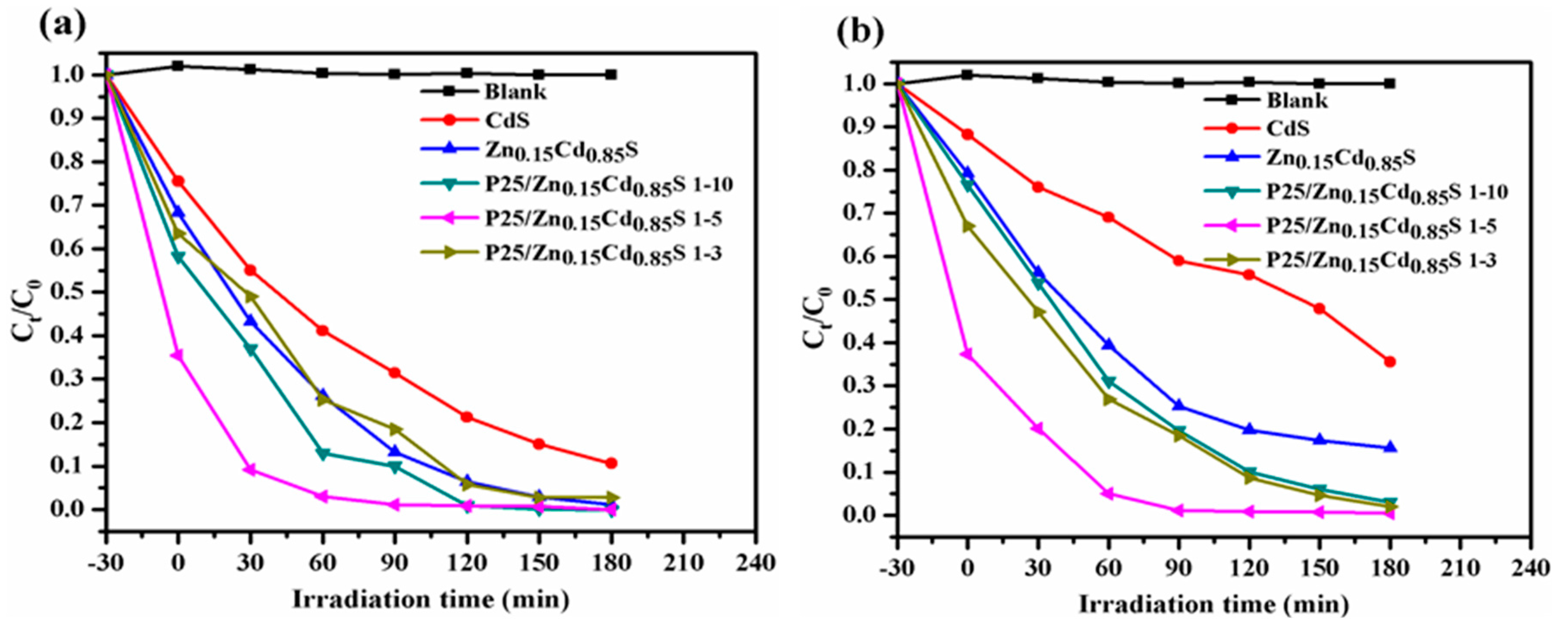
The photocatalytic performance of CdS, Zn0.15Cd0.85S nanoflowers and P25/Zn0.15Cd0.85S nanocomposite is assessed by the degradation of Rh-B molecules under visible light irradiation, as shown in Figure 5. All of the experiments are carried out under the similar conditions or otherwise mentioned. The Rh-B concentrations (C0) are determined from its absorption peak at 553 nm, and 80 mg of the catalysts are used. The reaction mixture containing the photocatalysts and Rh-B is stirred in dark for 30 min prior to the light irradiation, to establish the adsorption-desorption equilibrium between the Rh-B and the photocatalysts. It can be clearly seen that the sample of P25/Zn0.15Cd0.85S nanocomposite with P25:Cd ratio of 1:5 shows a strong adsorption ability towards the Rh-B with the adsorption up to 65% in dark, which is higher than those of the samples of pure CdS (25%) and Zn0.15Cd0.85S nanoflowers (32%). The adsorption capacity of nanocomposite materials depends on the crystallinity, the phase alignment and the surface area [43], thus the high adsorption performance of P25/Zn0.15Cd0.85S nanocomposite with P25:Cd ratio of 1:5 can be attributed to its high surface area as compared to the pure CdS and Zn0.15Cd0.85S nanoflowers. After the absorption process, the photocatalytic degradation activities of the samples are investigated, and the results show that all of the samples have the high efficiency for degradation Rh-B under visible light irritations. The P25/Zn0.15Cd0.85S nanocomposite with P25:Cd ratio of 1:5 shows the highest activity for the degradation of Rh-B and it takes about 60 min to completely degrade Rh-B, while the activities for degradation of Rh-B take about 180 min, 150 min, 120 min and 150 min in case of pure CdS, Zn0.15Cd0.85S nanoflowers, P25/Zn0.15Cd0.85S 1-10 and P25/Zn0.15Cd0.85S 1-3, respectively (Figure 5a). In order to minimize the impact of the physical adsorption on the photo-degradation, the photocatalysts amount is changed from 80 mg to 50 mg. Then, the photocatalytic degradation activities of the samples are investigated, all of the samples show better photocatalytic activities than pure CdS. The P25/Zn0.15Cd0.85S with P25:Cd ratio of 1:5 also shows the best performance towards Rh-B degradation and it could be completely degraded within 60 min of photoirradiation, as shown in Figure 5b. It is obvious from the results that under visible light irradiation, P25/Zn0.15Cd0.85S nanocomposites possess efficient separation of hole and electron, which would enhance the photo-degradation of dye. The results reveal that the photocatalytic ability of CdS nanoparticles towards degradation Rh-B is greatly enhanced after doping with Zn and decoration with P25, this could be due to the reason that the Zn doped CdS surface will create the flower-like structure with many small particles, which may favor the enhanced light absorption ability, as well as the fast electron transfer to avoid the recombination of the photo-induced electrons and holes between CdS and P25.
3.3. Scavengers Method
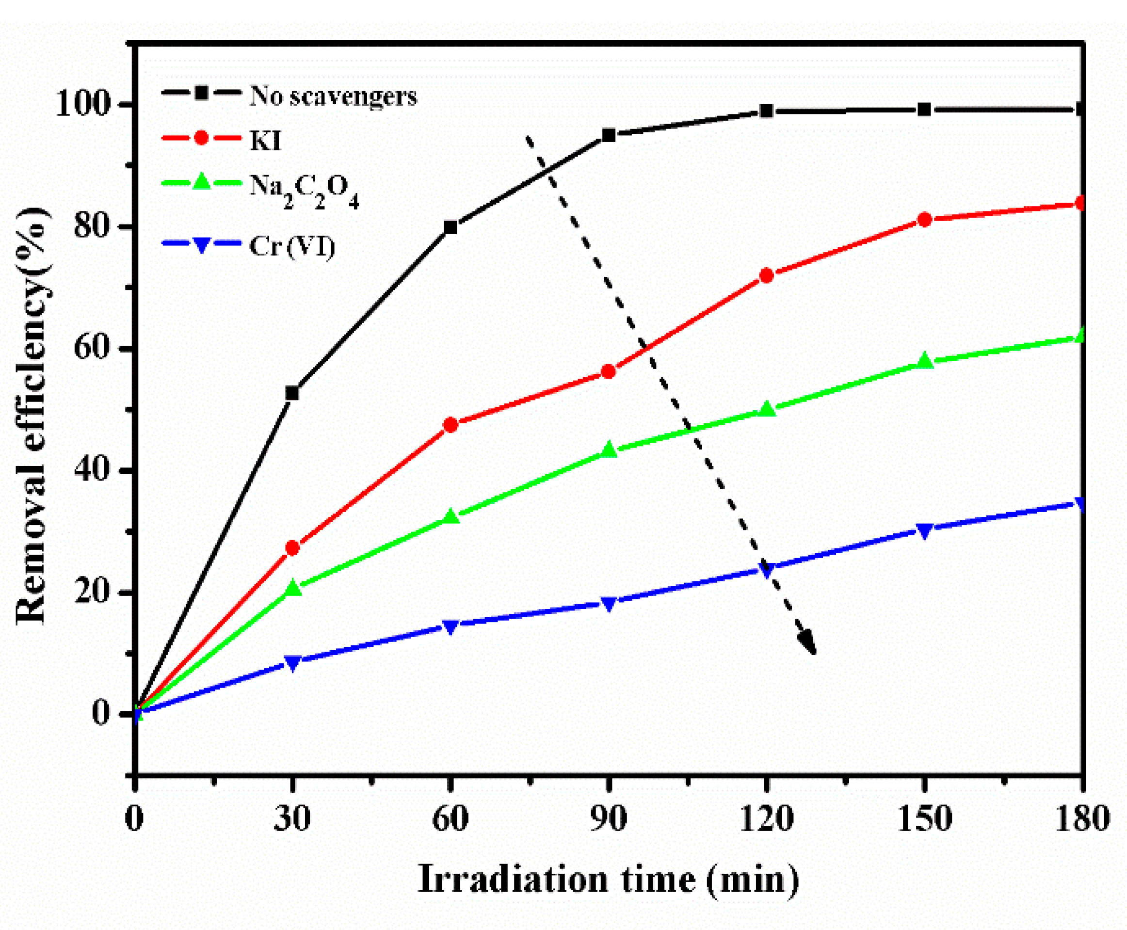
The photo-generated holes and electrons participate in the Rh-B degradation in the P25/Zn0.15Cd0.85S nanocomposite photocatalytic system. To confirm the generation of electron-hole pair and explore the mechanism of Rh-B degradation, some scavengers are used in the reaction mixture. Sodium oxalate is used as holes scavenger, KI is used as hole and ●OH scavengers and K2Cr2O7 is used for electrons scavenger [44]. Figure 6 shows the photo-degradation efficiency of Rh-B over P25/Zn0.15Cd0.85S nanocomposite with P25:Cd ratio of 1:5 in the presence of different scavengers. It can be seen that with the presence of Na2C2O4 and Cr (VI) under visible light, the photo-degradation of Rh-B declines to 48% and 22% after 120 min irradiation, respectively. While in the presence of KI, the photo-degradation of Rh-B decreases to 70%. Moreover, to suppress the electron process Cr(VI) was used as diagnostic tool for the formation of reactive species, the removal efficiency of Rh-B is lower than Na2C2O4. From Figure 6, it is observed that the photo catalytically generated electrons and holes radicals that are formed during the reaction in P25/Zn0.15Cd0.85S nanocomposites are responsible for the dye degradation. There is a high probability for the e− generated from Zn0.15Cd0.85S excitation to migrate towards TiO2, and thus the generation of h+ radicals is highly favorable. The excited ●OH also takes part in the generation of ●O2− radicals. Therefore, the photo-generated electrons play significant role in the degradation system under visible light.
3.4. Recyclability of Photocatalyst
The recyclability is among the factors which make the photocatalyst ideal for practical application. So, the reusability of pure CdS and P25/Zn0.15Cd0.85S nanocomposite 1–5 has been tested by photo-degrading of Rh-B for four cycles under visible light. The catalyst particles were centrifuged and dried at 80 °C after each cycle. The catalytic stability is shown in Figure 7. It represents Rh-B degradation with respect to each cycle, the repeated photodegradation shows that CdS is unstable and that there is loss of photocatalytic activity after two cycles of repeated experiments over pure CdS, as shown in Figure 7a, as CdS is photo-sensitive and will expose to photo-corrosion after dye photo-degradation. Figure 7b shows the repeated photodegradation over P25/Zn0.15Cd0.85S nanocomposite with P25: Cd ratio of 1:5, the catalysts maintain high photocatalytic activity after several times of being used. However, we can say that decorated Zn0.15Cd0.85S nanoflowers by P25 show consistent photocatalytic activity even after four cycles and enhance the transfer of electrons, which would increase the photocatalytic activity of the nanocomposite. As a powerful oxidizing agent, the ●OH radical may not be generated by single CdS nanocrystals because it will not oxidize OH groups to ●OH radicals due to its valence band potential and it will suffer photo-corrosion with releasing cadmium cations.
To further investigate the redox cycles that are involved in the degradation of Rh-B by P25/Zn0.15Cd0.85S with P25:Cd ratio of 1:5, XPS analysis of the sample after the 4th cycle of reaction is carried out, which provides spectroscopic evidences regarding the redox cycles. Figure 8a shows the XPS survey scans of the fresh and used P25/Zn0.15Cd0.85S with P25:Cd ratio of 1:5. The Cd 3d core level spectrum in Figure 8b indicates that there are two peaks in used P25/Zn0.15Cd0.85S with P25:Cd ratio of 1:5, which are similar to the fresh one in Figure 4b. The Ti 2p core level spectrum in Figure 8c and Zn 2p core level spectrum in Figure 8d indicate that there are two chemical species in the used P25/Zn0.15Cd0.85S with P25:Cd ratio of 1:5, which are also similar to fresh one in Figure 4d and Figure 4f, respectively. The results indicate that the catalyst has high stability after four cycles.
3.5. Mechanism of Photocatalytic Activity
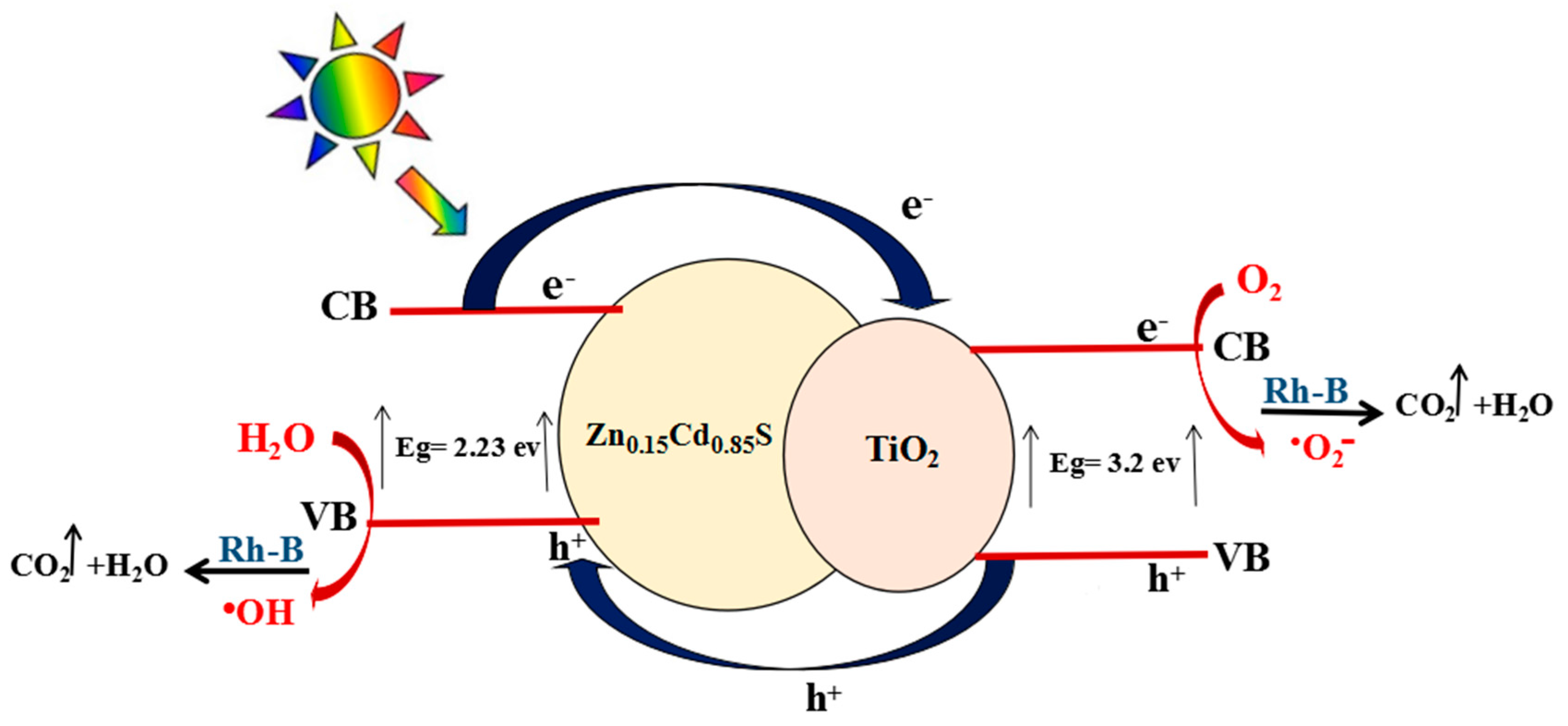
As shown in Figure 9, Zn0.15Cd0.85S nanoflowers and P25 with different band structures have a good compatibility with the absorbance of visible light. It leads to improve the transfer of photo-excited electron-hole pairs and reduce the recombination of photo-generated electrons and holes then improve the efficiency of photocatalytic degradation [43]. The more efficient charge-carrier separation and increased radical formation lead to the enhanced photocatalytic activity and improved stability of the P25/Zn0.15Cd0.85S nanocomposite. The use of P25 with high specific surface area and Zn0.15Cd0.85S with flower-like structure during hydrothermal preparation of P25/Zn0.15Cd0.85S nanocomposite is responsible for increasing the surface area and may improve absorption properties and then increase of the active sites, on which organic molecules and intermediate products are adsorbed. Based on the above discussion, in the reaction system under visible light irradiation, charge carriers are produced on the semiconductor of Zn0.15Cd0.85S to P25, the photo-excited electrons on the valence band (VB) of Zn0.15Cd0.85S can be promoted to the conduction band (CB). Then, the excited electrons transfer to the CB of TiO2 due to the fact that CB of TiO2 is slightly more positive than that of CdS. The electrons on the TiO2 would be trapped by adsorbed molecular O2 to form super oxide radicals ●O2−, which has the ability to degrade molecules of Rh-B. The holes will transfer from VB of TiO2 to CdS because VB band of TiO2 has lower energy than VB of CdS. Meanwhile, the holes that transferred from the VB of TiO2 could be consumed by Rh-B molecules adsorbed on the surface of P25/Zn0.15Cd0.85S nanocomposite and react with H2O to form ●OH radicals. Thus, recombination of electron-hole pairs can be efficiently inhibited by the reactive species, which prolong the catalyst lifetimes. P25/Zn0.15Cd0.85S nanocomposite system can induce a large light-harvesting efficiency and supply more reaction active sites to enhance the overall photocatalytic efficiency of the catalyst.
4. Conclusions
In summary, P25/Zn0.15Cd0.85S nanocomposite has been successfully synthesized by decorating Zn0.15Cd0.85S nanoflowers with P25 via one-step low temperature hydrothermal method. The new photocatalysts exhibit superior and durable photocatalytic activities for Rh-B photo-degradation. P25/Zn0.15Cd0.85S nanocomposite with P25:Cd ratio of 1:5 has high activity for the photo-degradation of Rh-B and high stability under visible light irradiation, and the rate of Rh-B degradation is much faster than those of pure CdS and all other tested samples. An explanation for the visible light induced photocatalytic activity of the coupled systems is provided, where the presence of P25 and Zn0.15Cd0.85S with different structures and energy levels for corresponding conduction and valence bands probably leads to the maximized photo-generated electrons and transport. Photo-generated holes and ●OH play a significant role in the degradation system, but electrons play the most important role.
Acknowledgments
This work is supported by the National Nature Science Foundation of China (No. 11674258, 51506155), the National Nature Science Foundation of Hubei Province (No. 2014CFB165, 2015CKC898), the Fundamental Research Funds for the Central Universities (No. 2017II22GX), Applied Basic Research Program of Wuhan (No. 2016010101010020) and Ministry of Higher Education from Kingdom of Saudi Arabia. Thanks for the measurements supporting from Center for Materials Research and Analysis at Wuhan University of Technology (WUT).
Author Contributions
Muneerah Al Omar conceived and designed the experiment, analyzed the data and wrote the first draft, Yueli Liu and Wen Chen gave relevant technical support, reviewed and edited the draft. All authors approved the manuscript.
Conflicts of Interest
The authors declare no conflict of interest.
References
- Lin, Y.; Li, D.; Hu, J.; Xiao, G.; Wang, J.; Li, W.; Fu, X. Highly efficient photocatalytic degradation of organic pollutants by PANI-modified TiO2 composite. J. Phys. Chem. C 2012, 116, 5764–5772. [Google Scholar] [CrossRef]
- Chen, F.; Jia, D.; Cao, Y.; Jin, X.; Liu, A. Facile synthesis of CdS nanorods with enhanced photocatalytic activity. Ceram. Int. 2015, 41, 14604–14609. [Google Scholar] [CrossRef]
- Huang, Z.; Chen, Z.; Chen, Z.; Lv, C.; Humphrey, M.G.; Zhang, C. Cobalt phosphide nanorods as an efficient electrocatalyst for the hydrogen evolution reaction. Nano Energy 2014, 9, 373–382. [Google Scholar] [CrossRef]
- Xiong, S.; Xi, B.; Qian, Y. CdS hierarchical nanostructures with tunable morphologies: Preparation and photocatalytic properties. J. Phys. Chem. C 2010, 114, 14029–14035. [Google Scholar] [CrossRef]
- Wu, S.-D.; Zhu, Z.; Zhang, Z.; Zhang, L. Preparation of the CdS semiconductor nanofibril by UV irradiation. Mater. Sci. Eng. B 2002, 90, 206–208. [Google Scholar] [CrossRef]
- Chang, W.-S.; Wu, C.-C.; Jeng, M.-S.; Cheng, K.-W.; Huang, C.-M.; Lee, T.-C. Ternary Ag–In–S polycrystalline films deposited using chemical bath deposition for photoelectrochemical applications. Mater. Chem. Phys. 2010, 120, 307–312. [Google Scholar] [CrossRef]
- Roy, A.; De, G.; Sasmal, N.; Bhattacharyya, S. Determination of the flatband potential of semiconductor particles in suspension by photovoltage measurement. Int. J. Hydrogen Energy 1995, 20, 627–630. [Google Scholar] [CrossRef]
- Ren, L.; Yang, F.; Deng, Y.-R.; Yan, N.-N.; Huang, S.; Lei, D.; Sun, Q.; Yu, Y. Synthesis of (CuIn)xCd2(1 − x)S2 photocatalysts for H2 evolution under visible light by using a low-temperature hydrothermal method. Int. J. Hydrogen Energy 2010, 35, 3297–3305. [Google Scholar] [CrossRef]
- Chauhan, R.; Kumar, A.; Chaudhary, R.P. Visible-light photocatalytic degradation of methylene blue with Fe doped CdS nanoparticles. Appl. Surf. Sci. 2013, 270, 655–660. [Google Scholar] [CrossRef]
- Wang, X.W.; Lui, G.; Chen, Z.-G.; Li, F.; Wang, L.Z.; Lu, G.Q.; Cheng, H.-M. Enhanced photocatalytic hydrogen evolution by prolonging the lifetime of carriers in ZnO/CdS heterostructures. Chem. Commun. 2009, 23, 3452–3454. [Google Scholar] [CrossRef] [PubMed]
- Sasikala, R.; Shirole, A.R.; Sudarsan, V.; Girija, K.G.; Rao, R.; Sudakar, C.; Bharadwaj, S.R. Improved photocatalytic activity of indium doped cadmium sulfide dispersed on zirconia. J. Mater. Chem. 2011, 21, 16566–16573. [Google Scholar] [CrossRef]
- Li, W.; Li, D.; Chen, Z.; Huang, H.; Sun, M.; He, Y.; Fu, X. High-efficient degradation of dyes by ZnxCd1 − xS solid solutions under visible light irradiation. J. Phys. Chem. C 2008, 112, 14943–14947. [Google Scholar] [CrossRef]
- Li, W.; Li, D.; Zhang, W.; Hu, Y.; He, Y.; Fu, X. Microwave synthesis of ZnxCd1 − xS nanorods and their photocatalytic activity under visible light. J. Phys. Chem. C 2010, 114, 2154–2159. [Google Scholar] [CrossRef]
- Yang, F.; Yan, N.-N.; Huang, S.; Sun, Q.; Zhang, L.-Z.; Yu, Y. Zn-doped CdS nanoarchitectures prepared by hydrothermal synthesis: Mechanism for enhanced photocatalytic activity and stability under visible light. J. Phys. Chem. C 2012, 116, 9078–9084. [Google Scholar] [CrossRef]
- Yang, F.; Messing, M.E.; Mergenthaler, K.; Ghasemi, M.; Johansson, J.; Wallenberg, L.R.; Pistol, M.-E.; Deppert, K.; Samuelson, L.; Magnusson, M.H. Zn-doping of GaAs nanowires grown by Aerotaxy. J. Cryst. Growth 2015, 414, 181–186. [Google Scholar] [CrossRef]
- Baghchesara, M.A.; Yousefi, R.; Cheraghizade, M.; Jamali-Sheini, F.; Saáedi, A. Photocurrent application of Zn-doped CdS nanostructures grown by thermal evaporation method. Ceram. Int. 2016, 42, 1891–1896. [Google Scholar] [CrossRef]
- Chowdhury, C.; Karmakar, S.; Datta, A. Monolayer group IV–VI monochalcogenides: Low-dimensional materials for photocatalytic water splitting. J. Phys. Chem. C 2017, 121, 7615–7624. [Google Scholar] [CrossRef]
- Liu, Y.; Kanhere, P.D.; Wong, C.L.; Tian, Y.; Feng, Y.; Boey, F.; Wu, T.; Chen, H.; White, T.J.; Chen, Z.; et al. Hydrazine-hydrothermal method to synthesize three-dimensional chalcogenide framework for photocatalytic hydrogen generation. J. Solid State Chem. 2010, 183, 2644–2649. [Google Scholar] [CrossRef]
- Nie, L.; Zhang, Q. Recent progress in crystalline metal chalcogenides as efficient photocatalysts for organic pollutant degradation. Inorg. Chem. Front. 2017, 4, 1953–1962. [Google Scholar] [CrossRef]
- Reshak, A.H. Active photocatalytic water splitting solar-to-hydrogen energy conversion: Chalcogenide photocatalyst Ba2ZnSe3 under visible irradiation. Appl. Catal. B Environ. 2018, 221, 17–26. [Google Scholar] [CrossRef]
- Wang, J.; Meng, J.; Li, Q.; Yang, J. Single-layer cadmium chalcogenides: Promising visible-light driven photocatalysts for water splitting. Phys. Chem. Chem. Phys. 2016, 18, 17029–17036. [Google Scholar] [CrossRef] [PubMed]
- Ma, C.Y.; Mu, Z.; Li, J.J.; Jin, Y.G.; Cheng, J.; Lu, G.Q.; Hao, Z.P.; Qiao, S.Z. Mesoporous Co3O4 and Au/Co3O4 catalysts for low-temperature oxidation of trace ethylene. J. Am. Chem. Soc. 2010, 132, 2608–2613. [Google Scholar] [CrossRef] [PubMed]
- Ni, M.; Leung, M.K.; Leung, D.Y.; Sumathy, K. A review and recent developments in photocatalytic water-splitting using TiO2 for hydrogen production. Renew. Sustain. Energy Rev. 2007, 11, 401–425. [Google Scholar] [CrossRef]
- Zhang, Y.J.; Yan, W.; Wu, Y.P.; Wang, Z.H. Synthesis of TiO2 nanotubes coupled with CdS nanoparticles and production of hydrogen by photocatalytic water decomposition. Mater. Lett. 2008, 62, 3846–3848. [Google Scholar] [CrossRef]
- Basahel, S.N.; Lee, K.; Hahn, R.; Schmuki, P.; Bawaked, S.M.; Al-Thabaiti, S.A. Self-decoration of Pt metal particles on TiO2 nanotubes used for highly efficient photocatalytic H2 production. Chem. Commun. 2014, 50, 6123–6125. [Google Scholar] [CrossRef] [PubMed]
- Cho, C.; Lee, J.; Lee, D.C.; Moon, J.H. Uniform decoration of CdS nanoparticles on TiO2 inverse opals for visible light photoelectrochemical cell. Electrochim. Acta 2015, 166, 350–355. [Google Scholar] [CrossRef]
- Tsuji, I.; Kato, H.; Kobayashi, H.; Kudo, A. Photocatalytic H2 evolution reaction from aqueous solutions over band structure-controlled (AgIn)xZn2(1− x)S2 solid solution photocatalysts with visible-light response and their surface nanostructures. J. Am. Chem. Soc. 2004, 126, 13406–13413. [Google Scholar] [CrossRef] [PubMed]
- Tian, G.; Chen, Y.; Zhou, W.; Pan, K.; Tian, C.; Huang, X.-R.; Fu, H. 3D hierarchical flower-like TiO2 nanostructure: Morphology control and its photocatalytic property. CrystEngComm 2011, 13, 2994–3000. [Google Scholar] [CrossRef]
- Hu, Z.; Quan, H.; Chen, Z.; Shao, Y.; Li, D. New insight into an efficient visible light-driven photocatalytic organic transformation over CdS/TiO2 photocatalysts. Photochem. Photobiol. Sci. 2018, 17, 51–59. [Google Scholar] [CrossRef] [PubMed]
- Yu, J.; Li, C.; Liu, S. Effect of PSS on morphology and optical properties of ZnO. J. Colloid Interface Sci. 2008, 326, 433–438. [Google Scholar] [CrossRef] [PubMed]
- Weller, H. Colloidal semiconductor Q-particles: Chemistry in the transition region between solid state and molecules. Angew. Chem. Int. Ed. 1993, 32, 41–53. [Google Scholar] [CrossRef]
- Su, X.; Zhao, J.; Li, Y.; Zhu, Y.; Ma, X.; Sun, F.; Wang, Z. Solution synthesis of Cu2O/TiO2 core-shell nanocomposites. Colloids Surf. A Physicochem. Eng. Asp. 2009, 349, 151–155. [Google Scholar] [CrossRef]
- Liu, Y.; Yu, H.; Quan, X.; Chen, S. Green synthesis of feather-shaped MoS2/CdS photocatalyst for effective hydrogen production. Int. J. Photoenergy 2013, 2013, 247516. [Google Scholar] [CrossRef]
- Setty, M. Burstein effect in thick films of cadmium orthostannate (Cd2SnO4). J. Mater. Sci. Lett. 1987, 6, 909–911. [Google Scholar] [CrossRef]
- Houng, M.; Fu, S.; Wu, T. Effect of surface chemisorption on the photoconductivity enhancement of CdS thick films. J. Mater. Sci. Lett. 1986, 5, 96–98. [Google Scholar] [CrossRef]
- Gonbeau, D.; Guimon, C.; Pfister-Guillouzo, G.; Levasseur, A.; Meunier, G.; Dormoy, R. XPS study of thin films of titanium oxysulfides. Surf. Sci. 1991, 254, 81–89. [Google Scholar] [CrossRef]
- Slink, W.E.; De Groot, P.B. Vanadium-titanium oxide catalysts for oxidation of butene to acetic acid. J. Catal. 1981, 68, 423–432. [Google Scholar] [CrossRef]
- Sanjines, R.; Tang, H.; Berger, H.; Gozzo, F.; Margaritondo, G.; Levy, F. Electronic structure of anatase TiO2 oxide. J. Appl. Phys. 1994, 75, 2945–2951. [Google Scholar] [CrossRef]
- Leinen, D.; Fernandez, A.; Espinos, J.; Belderrain, T.; González-Elipe, A. Ion beam induced chemical vapor deposition for the preparation of thin film oxides. Thin Solid Films 1994, 241, 198–201. [Google Scholar] [CrossRef]
- Chadwick, D.; Hashemi, T. Adsorbed corrosion inhibitors studied by electron spectroscopy: Benzotriazole on copper and copper alloys. Corros. Sci. 1978, 18, 39–51. [Google Scholar] [CrossRef]
- Kowalczyk, S.; Ley, L.; McFeely, F.; Pollak, R.; Shirley, D. Relative effect of extra-atomic relaxation on Auger and binding-energy shifts in transition metals and salts. Phys. Rev. B 1974, 9, 381. [Google Scholar] [CrossRef]
- Wagner, C.D. Chemical shifts of Auger lines, and the Auger parameter. Faraday Discuss. Chem. Soc. 1975, 60, 291–300. [Google Scholar] [CrossRef]
- Xu, X.; Lu, R.; Zhao, X.; Xu, S.; Lei, X.; Zhang, F.; Evans, D.G. Fabrication and photocatalytic performance of a ZnxCd1 − xS solid solution prepared by sulfuration of a single layered double hydroxide precursor. Appl. Catal. B Environ. 2011, 102, 147–156. [Google Scholar] [CrossRef]
- Zhang, L.-S.; Wong, K.-H.; Zhang, D.-Q.; Hu, C.; Jimmy, C.Y.; Chan, C.-Y.; Wong, P.-K. Zn:In(OH)ySz solid solution nanoplates: Synthesis, characterization, and photocatalytic mechanism. Environ. Sci. Technol. 2009, 43, 7883–7888. [Google Scholar] [CrossRef] [PubMed]
Figure 1.
(a) XRD patterns of pure CdS nanoparticles, Zn0.15Cd0.85S nanoflowers and P25/Zn0.15Cd0.85S nanocomposite with P25:Cd of 1:10, 1:5 and 1:3, and the enlarged peaks corresponding to (b) (110) and (c) (112) crystal plane for CdS nanoparticles and Zn0.15Cd0.85S nanoflowers.
Figure 1.
(a) XRD patterns of pure CdS nanoparticles, Zn0.15Cd0.85S nanoflowers and P25/Zn0.15Cd0.85S nanocomposite with P25:Cd of 1:10, 1:5 and 1:3, and the enlarged peaks corresponding to (b) (110) and (c) (112) crystal plane for CdS nanoparticles and Zn0.15Cd0.85S nanoflowers.

Figure 2.
Scanning electron microscopy images of (a) pure CdS nanoparticles, (b) Zn0.15Cd0.85S nanoflowers and (c) P25/Zn0.15Cd0.85S nanocomposite with P25:Cd of 1:10, (d) 1:5 and (e) 1:3, bright field TEM image of (f) Zn0.15Cd0.85S nanoflowers, and (g) P25/Zn0.15Cd0.85S 1-5 and (h) HRTEM image of P25/Zn0.15Cd0.85S 1-5.

Figure 3.
UV-vis absorbance spectra of pure CdS nanoparticles, Zn0.15Cd0.85S nanoflowers, and P25/Zn0.15Cd0.85S nanocomposite with P25:Cd of 1:10, 1:5 and 1:3.
Figure 3.
UV-vis absorbance spectra of pure CdS nanoparticles, Zn0.15Cd0.85S nanoflowers, and P25/Zn0.15Cd0.85S nanocomposite with P25:Cd of 1:10, 1:5 and 1:3.
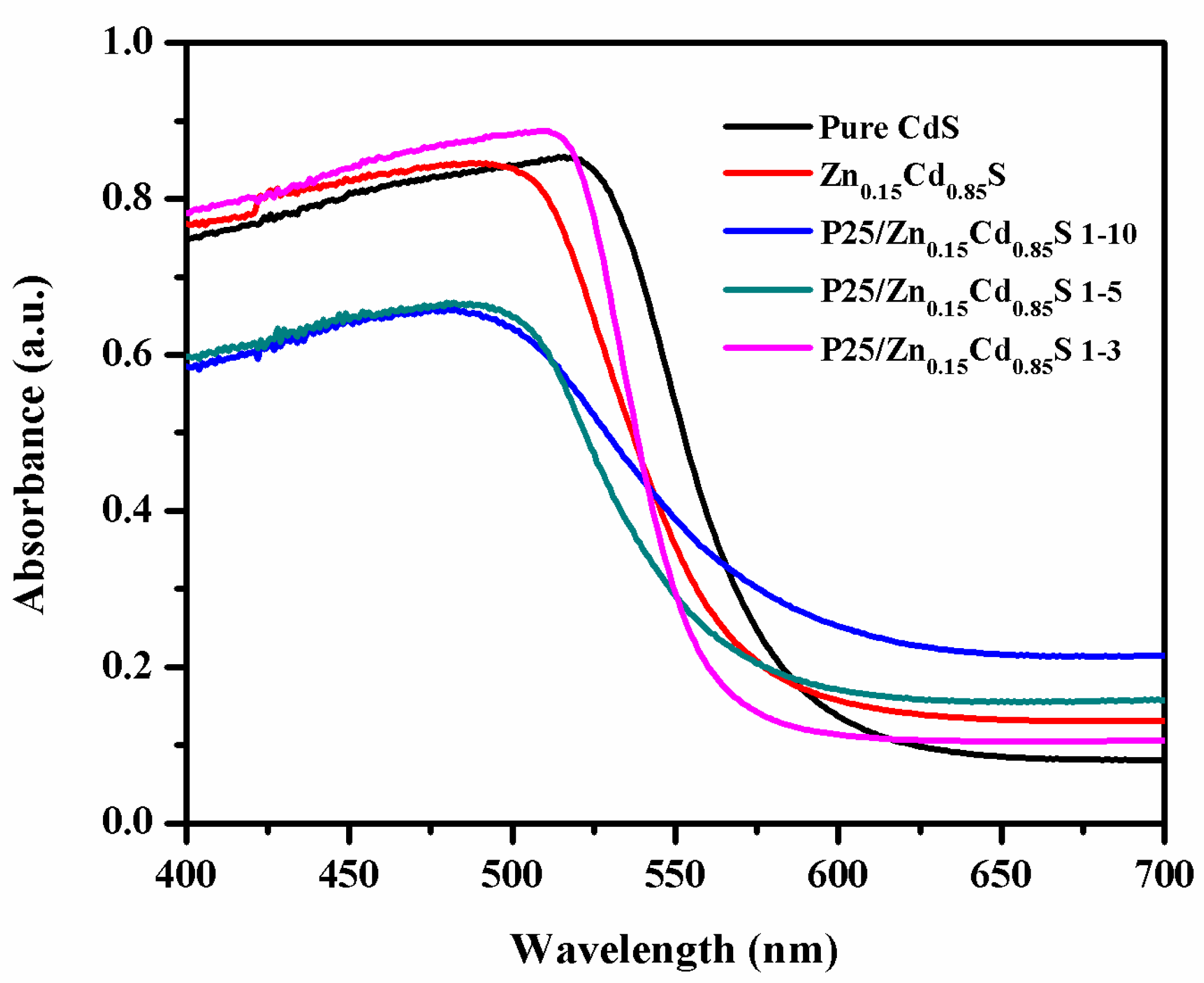
Figure 4.
High resolution X-ray photoelectron spectra (XPS) of pure CdS nanoparticles and P25/Zn0.15Cd0.85S nanocomposite (1-5), (a) survey spectra, (b) Cd 3d, (c) S 2p, (d) Ti 2p, (e) O 1s, and (f) Zn 2p.
Figure 4.
High resolution X-ray photoelectron spectra (XPS) of pure CdS nanoparticles and P25/Zn0.15Cd0.85S nanocomposite (1-5), (a) survey spectra, (b) Cd 3d, (c) S 2p, (d) Ti 2p, (e) O 1s, and (f) Zn 2p.
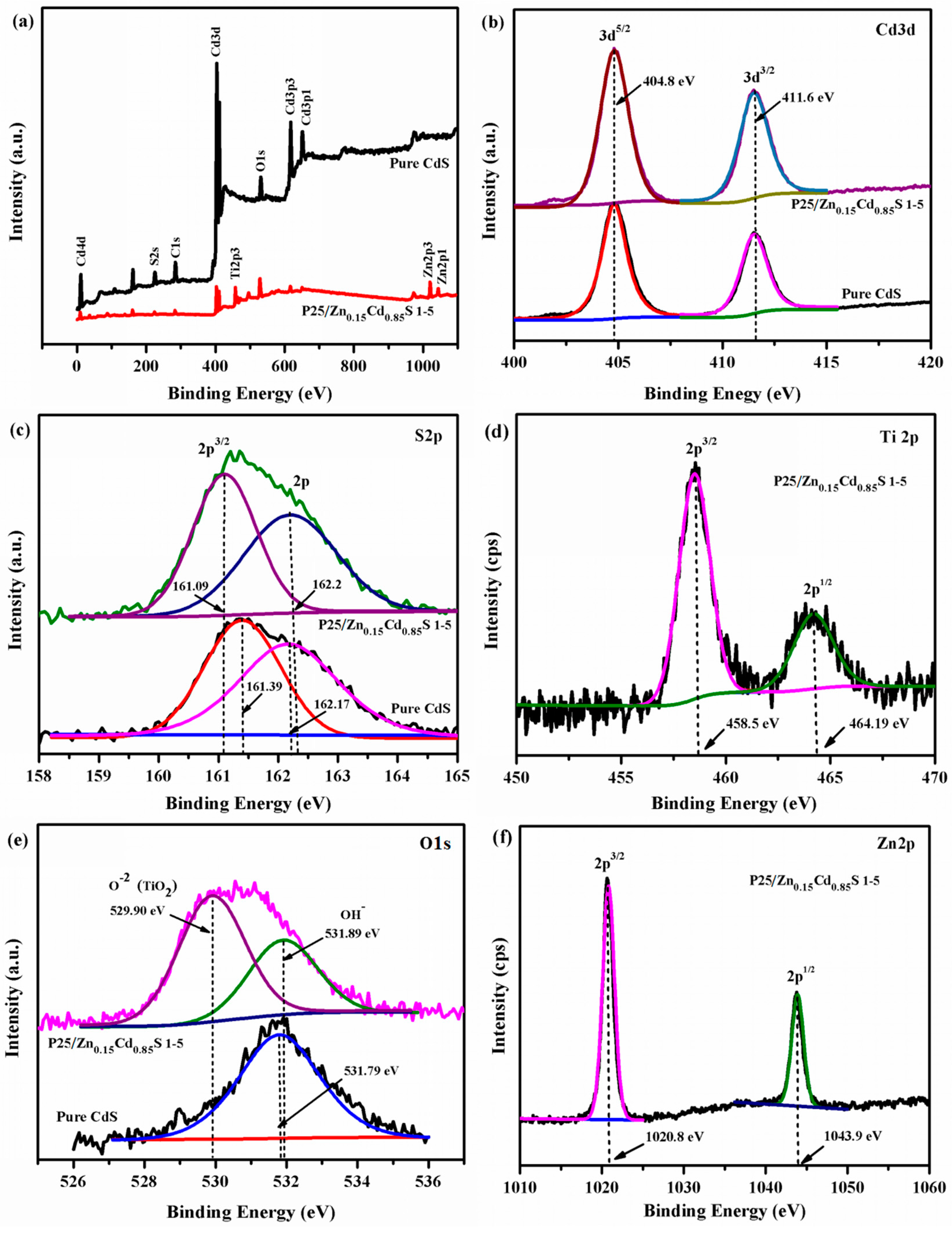
Figure 5.
Photo-degradation of Rh-B (100 mL, 30 mg/L) by different photocatalysts amounts (a) 80 mg and (b) 50 mg of various samples
Figure 5.
Photo-degradation of Rh-B (100 mL, 30 mg/L) by different photocatalysts amounts (a) 80 mg and (b) 50 mg of various samples

Figure 6.
Photo-degradation efficiency of RhB (100 mL, 30 mg/L) over 80 mg of P25/Zn0.15Cd0.85S nanocomposites 1-5 with P25: Cd ratio of 1:5, under visible light with the presence of different scavengers.
Figure 6.
Photo-degradation efficiency of RhB (100 mL, 30 mg/L) over 80 mg of P25/Zn0.15Cd0.85S nanocomposites 1-5 with P25: Cd ratio of 1:5, under visible light with the presence of different scavengers.

Figure 7.
Repeated experiments of photocatalytic degradation of RhB (100 mL, 30 mg/L) over (a) pure CdS and (b) P25/Zn0.15Cd0.85S nanocomposites 1-5 under visible light irradiation.
Figure 7.
Repeated experiments of photocatalytic degradation of RhB (100 mL, 30 mg/L) over (a) pure CdS and (b) P25/Zn0.15Cd0.85S nanocomposites 1-5 under visible light irradiation.
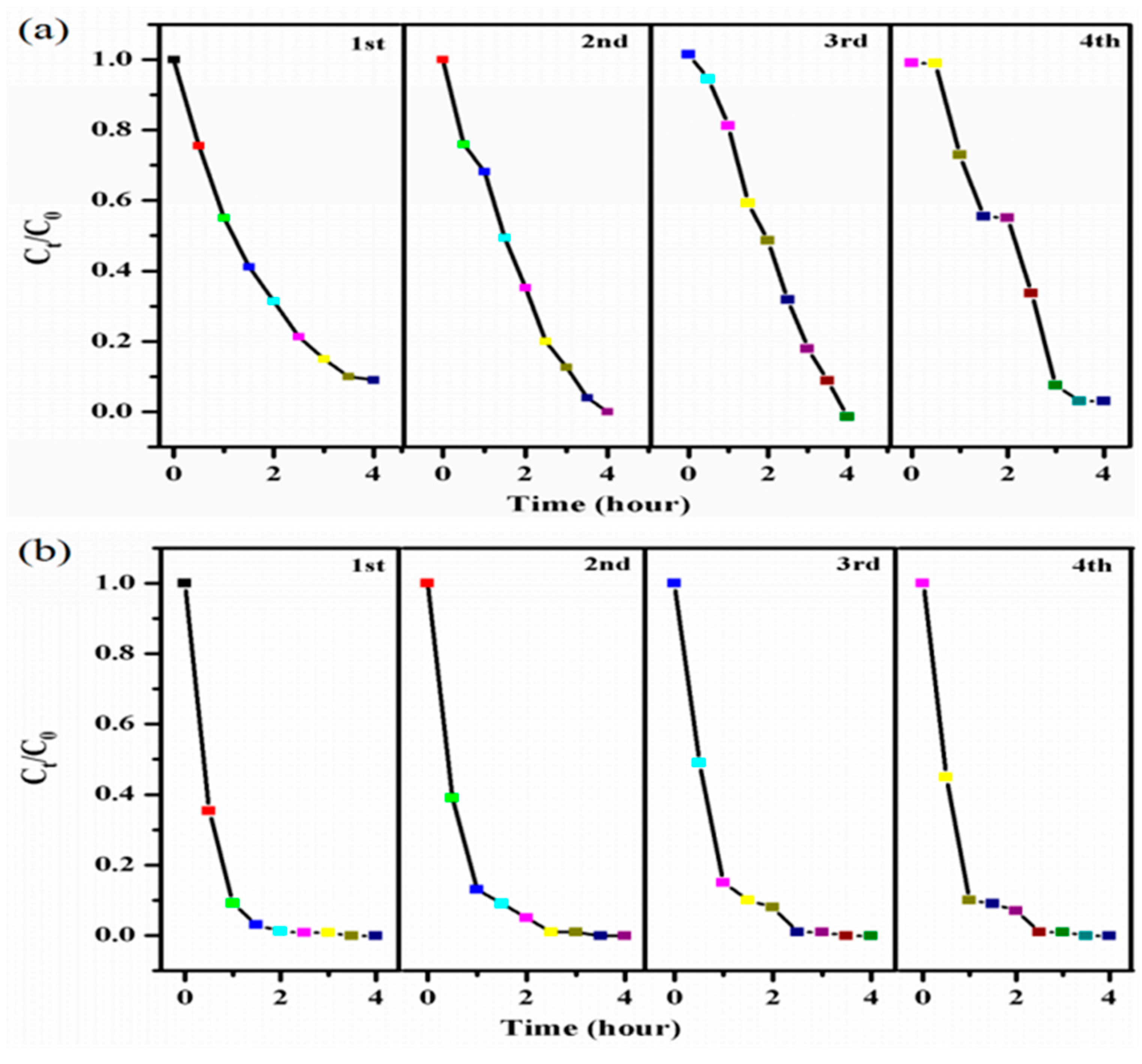
Figure 8.
XPS survey scan spectra of fresh and used of P25/Zn0.15Cd0.85S nanocomposite with P25:Cd ratio of 1:5 (a) and high resolution XPS spectra of used P25/Zn0.15Cd0.85S nanocomposite 1-5, (b) Cd 3d, (c) Ti 2p, and (d) Zn 2p.
Figure 8.
XPS survey scan spectra of fresh and used of P25/Zn0.15Cd0.85S nanocomposite with P25:Cd ratio of 1:5 (a) and high resolution XPS spectra of used P25/Zn0.15Cd0.85S nanocomposite 1-5, (b) Cd 3d, (c) Ti 2p, and (d) Zn 2p.
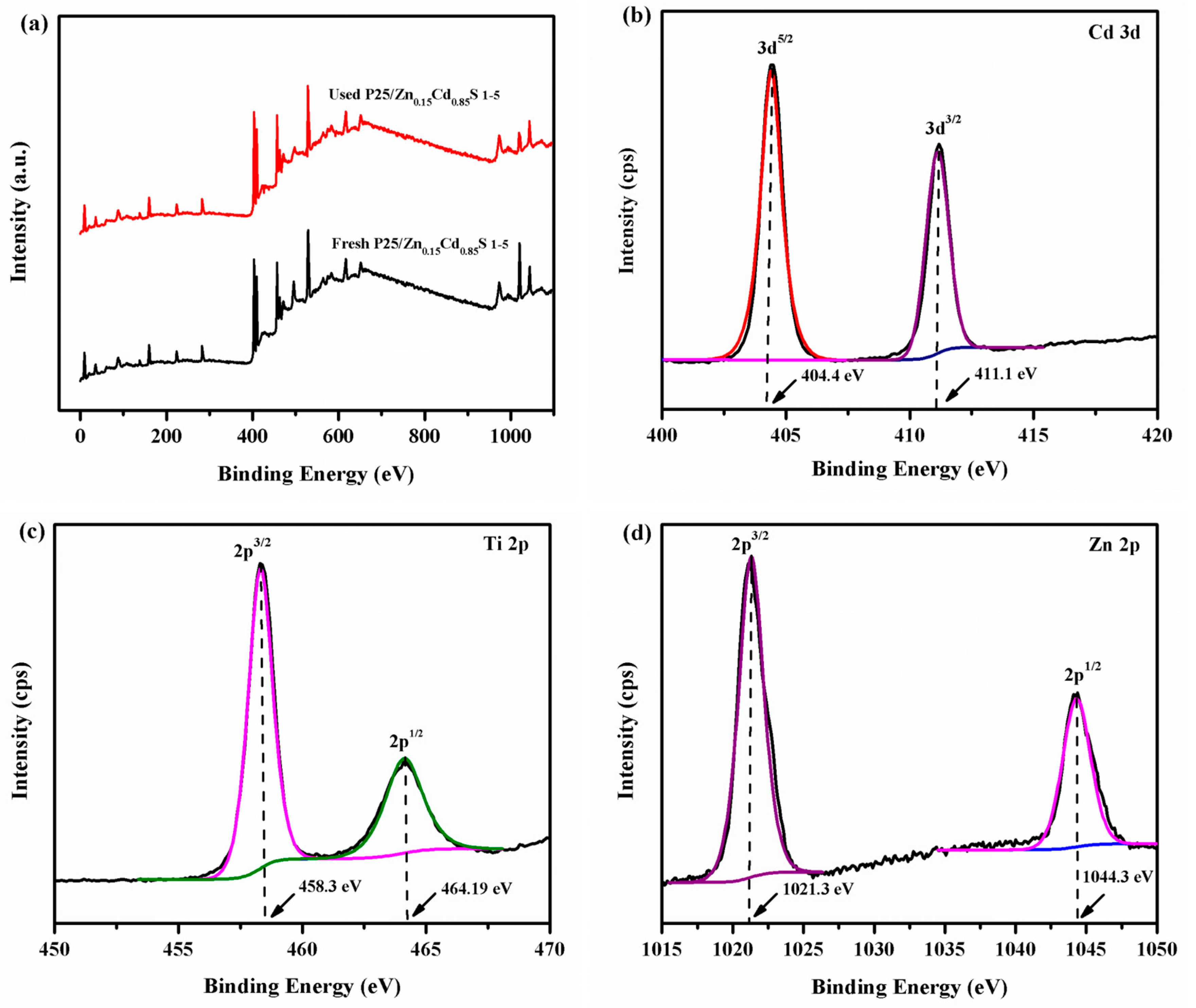
Figure 9.
Schematic illustration of charge-transfer in P25/Zn0.15Cd0.85S nanocomposite for photocatalytic activity induced by the light irradiation.
Figure 9.
Schematic illustration of charge-transfer in P25/Zn0.15Cd0.85S nanocomposite for photocatalytic activity induced by the light irradiation.


Table 1.
Sample label, molar ratio, Bruauer−Emmett−Telle (BET) surface area, and band gap of pure CdS, Zn0.15Cd0.85S nanoflowers, and P25/Zn0.15Cd0.85S nanocomposite.
Table 1.
Sample label, molar ratio, Bruauer−Emmett−Telle (BET) surface area, and band gap of pure CdS, Zn0.15Cd0.85S nanoflowers, and P25/Zn0.15Cd0.85S nanocomposite.
| Sample Label | Molar Ratio P25:Cd | BET (m2·g−1) | Band Gap (eV) |
|---|---|---|---|
| CdS | - | 0.26 | 2.20 |
| Zn0.15Cd0.85S | - | 0.63 | 2.23 |
| P25/Zn0.15Cd0.85S 1-10 | 1:10 | 7.50 | 2.24 |
| P25/Zn0.15Cd0.85S 1-5 | 1:5 | 21.4 | 2.28 |
| P25/Zn0.15Cd0.85S 1-3 | 1:3 | 37.8 | 2.30 |
© 2018 by the authors. Licensee MDPI, Basel, Switzerland. This article is an open access article distributed under the terms and conditions of the Creative Commons Attribution (CC BY) license (http://creativecommons.org/licenses/by/4.0/).
Share and Cite
MDPI and ACS Style
Alomar, M.; Liu, Y.; Chen, W. Surface Decorated Zn0.15Cd0.85S Nanoflowers with P25 for Enhanced Visible Light Driven Photocatalytic Degradation of Rh-B and Stability. Appl. Sci. 2018, 8, 327. https://doi.org/10.3390/app8030327
AMA Style
Alomar M, Liu Y, Chen W. Surface Decorated Zn0.15Cd0.85S Nanoflowers with P25 for Enhanced Visible Light Driven Photocatalytic Degradation of Rh-B and Stability. Applied Sciences. 2018; 8(3):327. https://doi.org/10.3390/app8030327
Chicago/Turabian StyleAlomar, Muneerah, Yueli Liu, and Wen Chen. 2018. "Surface Decorated Zn0.15Cd0.85S Nanoflowers with P25 for Enhanced Visible Light Driven Photocatalytic Degradation of Rh-B and Stability" Applied Sciences 8, no. 3: 327. https://doi.org/10.3390/app8030327
Note that from the first issue of 2016, this journal uses article numbers instead of page numbers. See further details here.