Minkowski Island and Crossbar Fractal Microstrip Antennas for Broadband Applications


Faculty of Electronics, Military University of Technology, 00-809 Warsaw, Poland
*
Author to whom correspondence should be addressed.
Appl. Sci. 2018, 8(3), 334; https://doi.org/10.3390/app8030334
Submission received: 4 February 2018
/
Revised: 22 February 2018
/
Accepted: 24 February 2018
/
Published: 27 February 2018
(This article belongs to the Special Issue Metasurfaces: Physics and Applications)
Abstract
:The paper presents microstrip patch antennas, which are based on the fractal antenna concept, and use planar periodic geometries, providing improved characteristics. The properties of the fractal structure were used in a single-fractal layer design as well as in a design, which employs fractals on both the upper and bottom layers of the antenna. The final structure, i.e., a double-fractal layer antenna has been optimized to enhance bandwidth and gain of the microstrip antenna. The proposed geometry significantly improved antenna performance. The antenna could support an ultra-wide bandwidth ranging from 4.1 to 19.4 GHz, demonstrating higher gain with an average value of 6 dBi over the frequency range, and a radiation capability directed in the horizontal plane of the antenna.
1. Introduction
Antennas are a key element in wireless communication systems and one of the important problems in antenna design is to provide wideband characteristics. Telecommunication systems, especially those intended for military applications, should be equipped with an antenna capable of supporting a wideband or even ultra-wideband (UWB) frequency range. In addition, for some systems, such as cognitive radio, the antenna should allow for dynamically and autonomously emitting and/or receiving signals in the desired frequency ranges [1]. The efficiency of a radio broadcasting system is directly related to the characteristics of its antenna. Like other designs before them, microstrip antennas revolutionized antenna technology. Attractive properties of microstrip patch antennas—low profile, light weight, compact and conformable structure, and easy fabrication, make them good candidates for wireless systems. However, microstrip patch antennas have a narrow bandwidth, which is a significant drawback that limits their usefulness.
The conventional microstrip antenna consists of a metal strip conductor (patch) as an upper layer of a grounded substrate. The performance of microstrip antenna, in terms of bandwidth and radiation characteristics, is determined by its shape, dimensions and the dielectric constant of the substrate.
With the development of new materials called left-handed metamaterials (LHM), it is possible to create antenna designs with new properties. The microstrip antennas based on composite LHM should be characterized by simultaneously negative permittivity and permeability. Such materials exhibit counter-intuitive electromagnetic phenomena, such as reversed refraction. As a result, they can be referred to as negative refractive index (NRI) materials, since the wave vector forms a left-handed triplet.
Structures based on split ring resonators (SRR), with concentric rings separated by gaps in the ground plane, can yield to a material with simultaneously negative permittivity and permeability [2]. Such a metamaterial-based antenna can be smaller despite having improved properties. However, the antennas based on SRR and wire strips cannot achieve a sufficiently wide frequency range. This is why many different attempts have been proposed to widen the bandwidth of microstrip antenna using left-handed metamaterial structures. Among these, we can find a broadband planar antenna composed of unit cells and a dipole element having metamaterial property [3]. This configuration achieved a bandwidth of 1.2 GHz.
Planar left-handed metamaterial structures were proposed by Matsunaga et al. [4]. The presented structures consisted of 2D periodic arrays of unit cells on both the upper and lower layers. On the upper layer, 45-degree rotated square metal cells were placed, while, on the lower layer, four isosceles triangles were laid out and surrounded by a square frame. This configuration allowed for obtaining a frequency range, which is several times wider than one achieved by the same patch antenna without the periodic pattern.
Taking into account the fact that the main motivation of this work was to design an antenna with the widest possible bandwidth, the structure of the microstrip antenna was motivated by the advantages of using fractals in antenna engineering. The proposed antenna geometries were based on crossbar and Minkowski fractals, as an increased number of resonances over a given or fixed frequency band was reported for such antennas [5].
Fractal antennas are designs inspired by structures found in nature, and take up highly convoluted shapes. Fractal shapes applied in antenna designing can have various shapes and forms [3,6]. One can mention the following mathematically described shapes of fractals: Sierpinski carpet and gasket, Minkowski gasket, Koch snowflake, Mandelbrot set, crossbar, etc. These are the deterministic fractals, which can be used to create a scaled-down design with a recursive algorithm. The philosophy of fractal structure is that it can be subdivided into parts, with each part being a copy of the entire assembly, but reduced in size. One of the main benefits of the fractal structure is the increased electrical length of the antenna when compared to a conventional microstrip antenna. This property allows for the following advantages: it reduces the overall size of the antenna and produces multiple resonant bands. This benefit can be obtained due to the fractal geometry, as fractals have no characteristic size and could be treated as the composition of many copies of themselves at different scales. Best [5] pointed out that a fractal-shaped antenna demonstrates resonance compression and multi-band behavior. However, as it is underlined in [7], the fractal antenna with etched multiple slots suffers from the reduced overall gain, as a major part of the conducting strip is etched out.
Many types of fractal based microstrip antennas are presented in the literature, and their promising electrical properties were already revealed, but fractal structures were introduced mainly to the upper layers (patches), while the conducting ground planes were kept as monolithic strips.
Mosallaei et al. [8] and Yao et al. [9] presented microstrip antennas with periodic structures on the bottom layers. The bottom surface was constructed from periodic structures, based on square patches, which allowed for enhancing bandwidth despite the miniaturization of antennas.
Only a few papers discussed the electrical properties of microstrip antenna, where both the upper and the lower layers have periodic structures, as opposed to monolithic structures. Li-Wei et al. presented an antenna having upper and lower layers with periodic gaps designed in the form of isolated micro-triangles, while on the bottom ground plane has simple, periodically distributed cross strip-line gaps [10]. They obtained promising electrical properties—the working frequency bandwidth spanning from 200 MHz to 3 GHz.
In our previous work, we presented a microstrip antenna with both layers designed using periodic geometry [11]. The upper and lower layers of the antenna had fractal forms, but each fractal layer had a different shape. The Minkowski and crossbar fractals were taken into consideration.
In this work, the investigation of the electrical properties of fractal antennas with the following geometries was presented:
- -
- an antenna, in which the upper layer has fractal geometry while the lower layer has classical monolithic structure,
- -
- an antenna, in which the upper layer is a monolithic patch but the ground is a fractal,
- -
- an antenna, in which both layers (upper and lower) have fractal structures, but with the same type of fractal,
- -
- an antenna, in which both layers have fractal structures, each with a different type of fractal.
Taking into account the above demands, three kinds of antennas with fractals were investigated, i.e., crossbar fractal antennas, a Minkowski fractal antenna, and a crossbar and Minkowski fractals antenna, to recognize the impact of the type of fractal geometry on antenna properties. This also could be used to illustrate the benefits of fractal structures on the lower or upper layers and shows the level of proportional participation of each layer in the total electric properties of fractal antennas.
In all cases, the entire structure of the proposed antennas measures 27.6 × 31.8 mm2. The antennas were designed with the RT/Duroid® 5880 (Rogers Corporation, Killingly, CT, USA) low-loss substrate (tanδ = 0.0009 at 10 GHz) with dielectric constant of 2.2 and thickness of 0.79 mm.
2. The Conventional Reference Antenna
A rectangular microstrip patch antenna was designed to serve as a reference. The patch is 12 × 16 mm2, and the feeding line is 2.46 × 8 mm2 (Figure 1a). Note the asymmetrical geometry of the feeding line. Such configuration was mainly intended for the antenna with double-fractal layers presented in Figure 6. Nevertheless, all antennas analyzed below have the same asymmetrical geometry to ensure the same feeding condition. The simulated and measured values of reflection coefficient (S11 [dB]) of the conventional reference antenna are presented in Figure 1b.
3. The Crossbar Fractal Geometry
The microstrip antennas based on crossbar fractals offer the enhanced frequency band but also the improved radiation antenna pattern. El-Hameed et al. presented such fractal antenna, receiving the reflection coefficient better than −10 dB in the range of 3.1–11.5 GHz [12]. Particular applications for such a fractal with different three-stages (configurations) were discussed in [12,13,14]. The advantage of a crossbar fractal is that the number of stages can be adjusted to obtain the required multi band characteristics.
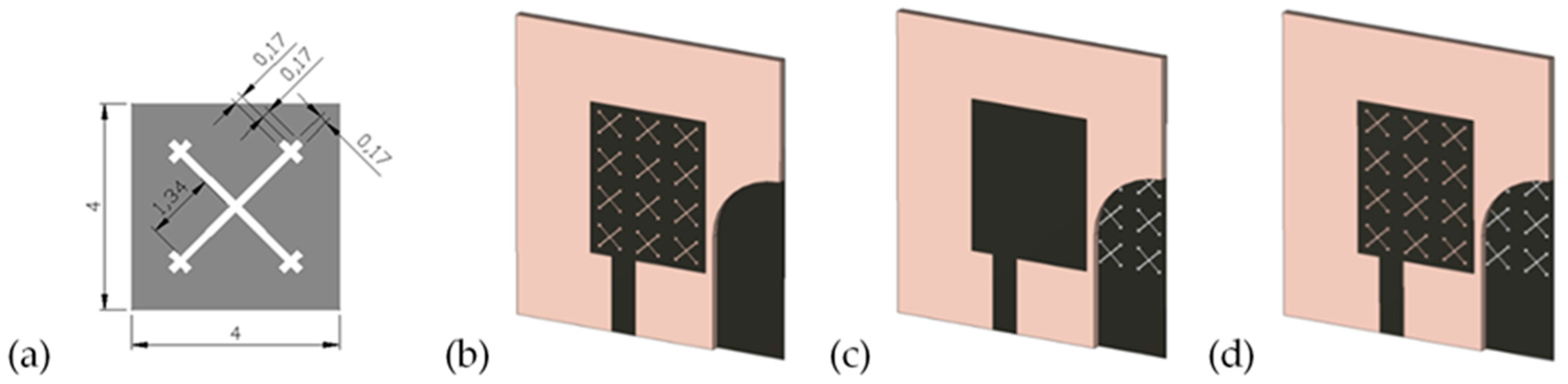
In this work, stage-2 of crossbar fractal tree structure, diagonally lying on the square unit cell of 4 × 4 mm2 has been taken into consideration—Figure 2a.
The following antenna configurations have been analyzed:
- (a)
- Configuration #1. The upper layer is based on a crossbar fractal structure and the lower layer is a solid conductive strip as in a conventional antenna. The upper patch consists of the 4 × 3 square unit cells with an edge of 4 mm in a periodic arrangement.
- (b)
- Configuration #2. The patch is a solid strip, but the ground layer is composed of 7 × 6 square unit cells with the crossbar fractal.
- (c)
- Configuration #3. Upper and lower layers are based on a crossbar fractal.
The above configurations of antennas have been presented in Figure 2b–d.
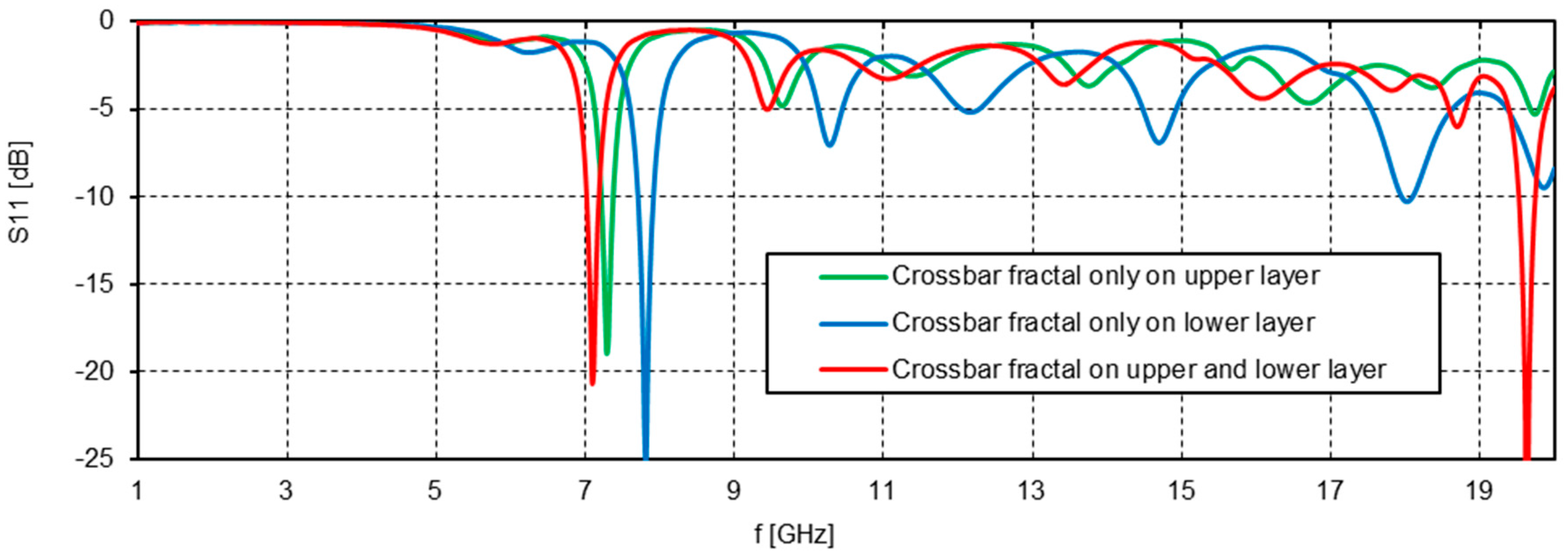
The reflection coefficients (S11 [dB]) for the above-mentioned configurations of antennas with crossbar fractal where depicted in Figure 3.
Reflection coefficients for analyzed antennas indicate the narrowband behavior for all configurations. Such property is practically similar to the conventional microstrip antennas. The only small displacements in frequency can be observed, depending on the proportional participation of the metal being etched out. Figure 3 shows that the crossbar fractal cannot make it possible to broaden the frequency band of the antennas. Nevertheless, one property of this fractal should be underlined—the deepness of the S11. Curves presented in Figure 3 have significantly smaller depth compared to the conventional antenna (Figure 1b). Such crossbar fractal smoothing property will be used with the final version of an antenna with double different fractal layers.
4. The Minkowski Island Fractal Geometry
Minkowski gasket is one of the earliest structures introduced into the antenna technique and is the most promising structure. Dhar et al. presented Minkowski fractals based microstrip antenna allowing for covering five different wireless standards [7]. Geometrical structure of presented antenna was loaded with a nearly square shaped dielectric resonator allowing for obtaining constant gain at all discrete frequencies. Moraes et al. [15] presented fractal antenna structure, based on Minkowski squares, operated at four resonant frequencies for WiMAX systems while Shafe et al. [16] described Minkowski fractal structure at three frequencies for WiMAX, WLAN and HiperLAN applications. Singh et al. showed that fractals are able to enlarge the frequency antenna operation if their structures are self-similar having the same basic appearance at every scale [17]. Dhar et al. showed the geometry of Minkowski fractal allowing for obtaining the wide bandwidth [3].
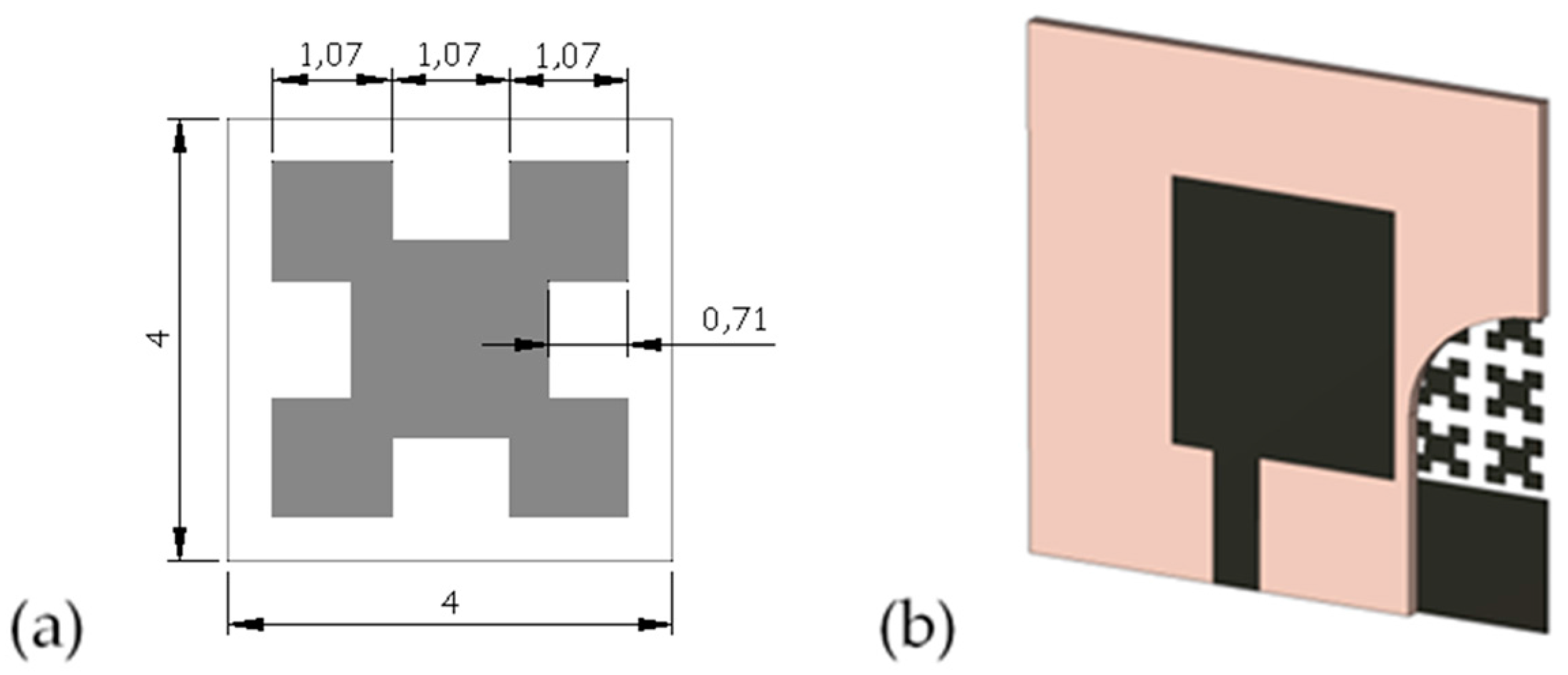
The iterative-generation of Minkowski fractals was discussed in [5,18,19]. Comissio [20] and Best [21] noted that resonant frequencies can be modified by adjusting the level of fractal iteration. In this investigation, the geometry of unit cell with the first iteration of Minkowski island, as depicted in Figure 4a, will be considered. It should be emphasized that the antenna behavior with increasing fractal iterations yields to worse electrical properties, resulting in decreasing broadbandedness of the antenna.
The Minkowski fractal based antenna was analyzed only for one configuration—the patch is a solid strip while the ground layer is composed of 7 × 6 square unit cells with Minkowski fractals, separated by slot gaps and placed in a periodic arrangement. This configuration of an antenna has been presented in Figure 4b.
In this work, the configuration when the upper layer is based on Minkowski fractal was not analyzed because of the problem with feeding. With the dimensions of Minkowski fractal (Figure 4a), the feeding line for the upper layer would have not the impedance of 50 Ω. Singh et al. [10] adapted the feeding technique to Minkowski fractal on the upper layer, but, in their solution, Minkowski fractal has modified geometry. Such modification results in different antenna geometry than that analyzed in this paper.
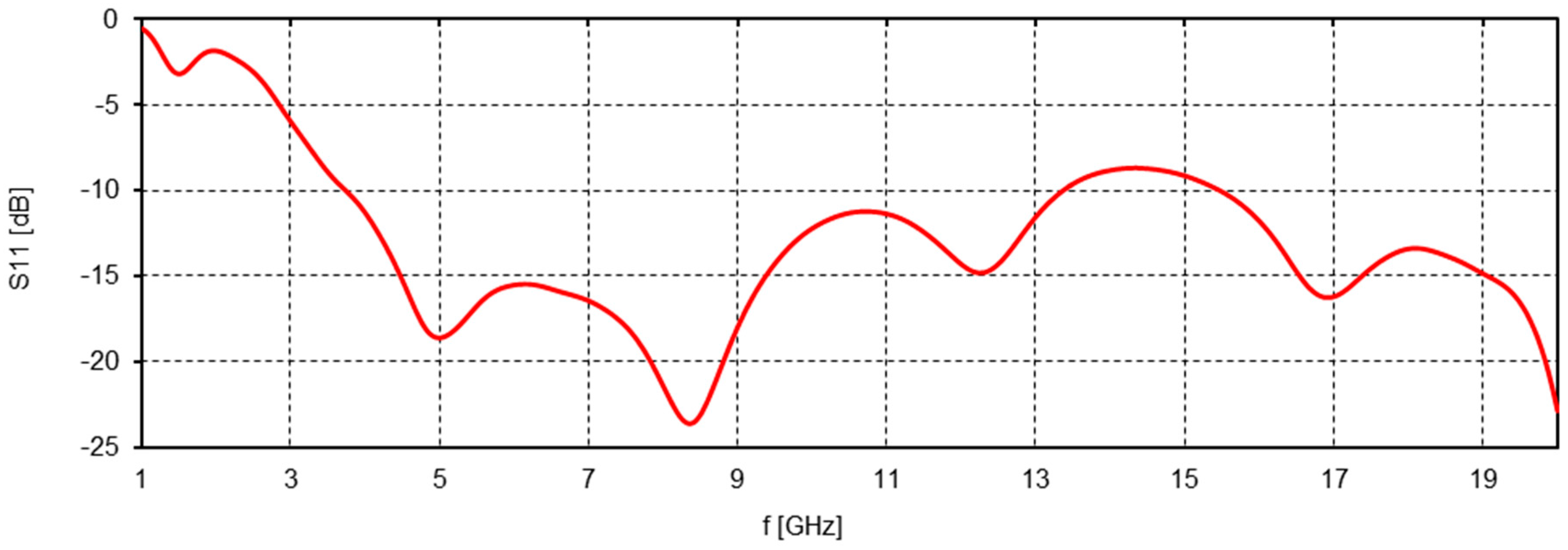
The reflection coefficients (S11 [dB]) for the above-mentioned configuration of antenna with Minkowski island fractal was depicted in Figure 5.
As shown in Figure 5, the plot of S11 demonstrates good reflection properties of the antenna in the frequencies from 4 to 13.5 GHz and above 15.7 GHz. However, the band from 13.5 to 15.7 GHz in unacceptable due reflection properties being too high. This disadvantage will be reduced or mitigated in the final version of the antenna, with the patch based on a crossbar fractal.
5. The Double-Fractal Layers Geometry Antenna
Taking into consideration the above investigation, the antenna with double fractal layers has been designed. The upper layer is based on a crossbar fractal, as presented in Figure 2a, while the ground has a Minkowski island fractal as is depicted in Figure 4a. The upper layer with the feeding line has an asymmetrical geometry. This feeding configuration enables an undisturbed flow of current from the feeding line to the patch. The final version of the antenna is presented in Figure 6. Double-fractal geometry was combined to obtain the optimal configuration of the antenna, the best S11 performance, and thus the largest bandwidth.
The reflection properties of the antenna have been presented in Figure 7.
Figure 7 demonstrates the widened bandwidth of the final version of the antenna, where the measured frequency range is even wider than the simulated one. It has achieved, at the level of −10 dB, a bandwidth ranging from 4.1 to 19.4 GHz, for a total bandwidth of 15.3 GHz. The figures show good correlation between measured and simulated values, and the very wide bandwidth of the proposed configuration.
The gain (G) of the proposed antenna was measured over the working bandwidth, from 4 to 18 GHz. The antenna achieved an average measured gain of 6 dBi and a maximum value of 10.9 dBi at 15.2 GHz. For lower frequencies, the value of gain falls, e.g., G = 5.9 dBi at 10 GHz, G = 4.5 dBi at 6 GHz. The efficiency improves with the growth of frequency. The following values of efficiency were obtained: of 86.4% at 7.96 GHz, of 88.3% at 9.22 GHz and of 89.7% at 11.48 GHz.
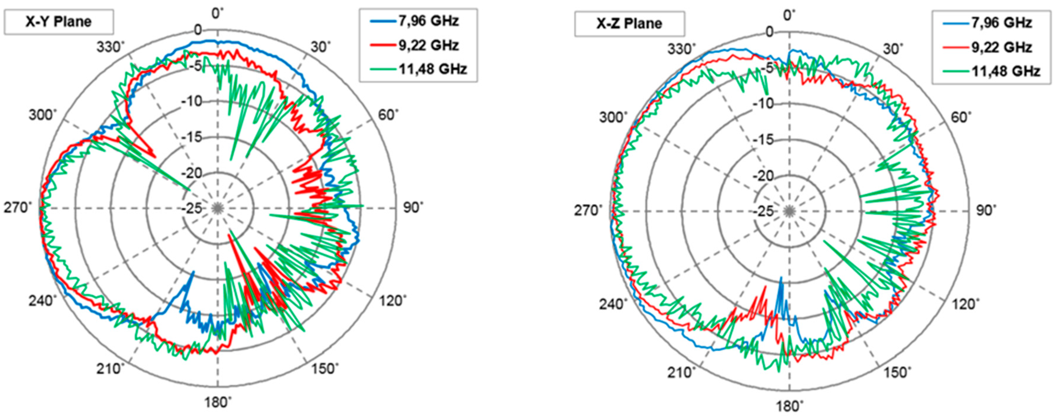
The radiation characteristics for proposed antenna were presented in Figure 8. Radiation patterns were measured in frequencies of 7.96, 9.22 and 11.48 GHz in the characteristic planes—“X-Y” and “X-Z”. These are the exampled frequencies for the frequency range of significantly low reflection property (7.96 and 11.48 GHz) as well as for the rather worse reflection coefficient (9.22 GHz). It can be seen that proposed geometry of the antenna resulted in a radiation spread of 270°. However, the shapes of radiation characteristics change in function of frequency. Future efforts should focus on obtaining similar shapes of radiation patterns in function of frequency to improve the efficiency of radio link.
6. Conclusions
In the paper, ultra-wideband antennas based on the planar periodic fractal geometry concepts were presented.
The electrical properties of antennas with one layer based on fractals were analyzed to recognize the influence of the fractal geometry on the broadbandedness of the antenna. The crossbar and Minkowski island fractals were taken into consideration.
The final antenna, based on double fractal layers, achieved the frequency range from 4.1 to 19.4 GHz, realizing a bandwidth of 15.3 GHz. Therefore, the bandwidth of manufactured antenna is 68 times larger than the bandwidth of a conventional microstrip antenna.
The antenna radiates at a 270° angle. The combination of the planar concept of the fractal shapes seems to be a good method to enhance the characteristics of the microstrip patch antenna. This antenna can easily be used in a communication system, where such enhanced features are required.
Acknowledgments
This work was supported by the National Centre for Research and Development (NCBR) of Poland under project No. DOB-1-1/1/PS/2014.
Author Contributions
All authors contributed substantially to the reported work. Roman Kubacki was the originator of the idea of this study and prepared the manuscript; Mirosław Czyżewski and Dariusz Laskowski provided the numerical calculations and performed the experiments.
Conflicts of Interest
The authors declare no conflict of interest.
References
- Swedheetha, C.; Suganya, M.; Gunapandian, P.; Manimegalai, B. Minkowski fractal based antenna for Cognitive Radio. In Proceedings of the 2014 IEEE International Microwave and RF Conference (IMaRC), Bangalore, India, 15–17 December 2014; pp. 166–169. [Google Scholar]
- Lee, Y.; Hao, Y. Characterization of microstrip patch antennas on metamaterial substrates loaded with complementary split-ring resonators. Microw. Opt. Technol. Lett. 2008, 50, 2131–2135. [Google Scholar] [CrossRef]
- Dhar, S.; Ghatak, R.; Gupta, B.; Poddar, D.R. A Wideband Minkowski Fractal Dielectric Resonator Antenna. IEEE Trans. Antennas Propag. 2013, 61, 2895–2903. [Google Scholar] [CrossRef]
- Matsunaga, N.; Sanada, A.; Kubo, H. Novel Two dimensional Planar Negative Refractive Index Structure. IEICE Trans. Electron. 2006, 9, 1276–1282. [Google Scholar] [CrossRef]
- Best, S.R. A Discussion on the Significance of Geometry in Determining the Resonant Behavior of Fractal and Other Non-Euclidean Wire Antennas. IEEE Antennas Propag. Mag. 2003, 45, 9–27. [Google Scholar] [CrossRef]
- Werner, D.H.; Ganguly, S. An Overview of Fractal Antenna Engineering Research. IEEE Antennas Propag. Mag. 2003, 45, 38–53. [Google Scholar] [CrossRef]
- Dhar, S.; Patra, K. A dielectric resonant-loaded Minkowski fractal-shaped slot loop heptaband antenna. IEEE Trans. Antennas Propag. 2015, 63, 1521–1525. [Google Scholar] [CrossRef]
- Mosallaei, H.; Sarabandi, K. Antenna Miniaturization and Bandwidth Enhancement Using a Reactive Impedance Substrate. IEEE Trans. Antennas Propag. 2004, 52, 2403–2414. [Google Scholar] [CrossRef]
- Yao, J.; Tchafa, F.M.; Jain, A.; Tjuatja, S.; Huang, H. Far-Field Interrogation of Microstrip Patch Antenna for Temperature Sensing without Electronics. IEEE Sens. J. 2016, 16, 7053–7060. [Google Scholar] [CrossRef]
- Le-Wei, L.; Ya-Nan, L.; Soon, Y.T.; Mosig, R.J.; Martin, J.F. A broadband and High Gain Metamaterial Antenna. Appl. Phys. Lett. 2010, 96, 1–3. [Google Scholar]
- Kubacki, R.; Lamari, S.; Czyżewski, M.; Laskowski, D. A broadband left-handed metamaterial microstrip antenna with double-fractal layers. Int. J. Antennas Propag. 2017, 2017, 1–6. [Google Scholar] [CrossRef]
- El-Hameed, A.S.; Salem, D.A.; Hashish, E.A. Crossbar fractal quasi self-complementary UWB antenna. In Proceedings of the 2014 IEEE Antennas and Propagation Society International Symposium (APSURSI), Memphis, TN, USA, 6–11 July 2014; pp. 219–220. [Google Scholar]
- Werner, D.H.; Lee, D. A Design Approach for Dual-Polarized Multiband Frequency Selective Surfaces Using Fractal Elements. IEEE Int. Symp. Antennas Propag. 2000, 3, 1692–1695. [Google Scholar]
- Werner, D.H.; Lee, D. Design of Dual-Polarized Multiband Frequency Selective Surfaces Using Fractal Elements. IEEE Electr. Lett. 2000, 36, 487–488. [Google Scholar] [CrossRef]
- Moraes, L.B.; Barbin, S.E. A comparison between Minkowski and Koch Fractal Patch antennas. In Proceedings of the 2011 SBMO/IEEE MTT-S International Microwave & Optoelectronics Conference (IMOC), Natal, Brazil, 29 October–1 November 2011; pp. 17–21. [Google Scholar]
- Shafe, S.N.; Adam, I.; Soh, P.J. Design and simulation of a modified Minkowski fractal antenna for tri-band application. In Proceedings of the Fourth Asia International Conference on Mathematical/Analytical Modelling and Computer Simulation, Bornea, Malaysia, 26–28 May 2010; pp. 567–570. [Google Scholar]
- Singh, A.; Kumar, M. Design and Simulation of Miniaturized Minkowski Fractal Antennas for microwave applications. Int. J. Adv. Res. Comput. Commun. Eng. 2014, 3, 5309–5311. [Google Scholar]
- Comisso, M. On The Use Of Dimension And Lacunarity for Comparing the Resonant Behavior of Convoluted Wire Antennas. Prog. Electromagnet. Res. 2009, 96, 361–376. [Google Scholar] [CrossRef]
- Gianvittorio, J.P.; Rahmat-Samii, Y. Fractal Antennas: A Novel Antenna Miniaturization technique and Application. IEEE Antennas Propag. Mag. 2002, 44, 20–36. [Google Scholar] [CrossRef]
- Comisso, M. Theoretical and Numerical Analysis of the Resonant Behaviour of the Minkowski Fractal Dipole Antenna. IET Microw. Antennas Propag. 2009, 3, 456–464. [Google Scholar] [CrossRef]
- Best, S.R. A Comparison of the Performance Properties of the Hilbert Curve Fractal and Meander Line Monopole Antennas. Microw. Opt. Technol. Lett. 2002, 35, 258–262. [Google Scholar] [CrossRef]
Figure 1.
(a) Geometry of conventional microstrip antenna; (b) simulated and measured S11 of the conventional microstrip antenna.
Figure 1.
(a) Geometry of conventional microstrip antenna; (b) simulated and measured S11 of the conventional microstrip antenna.
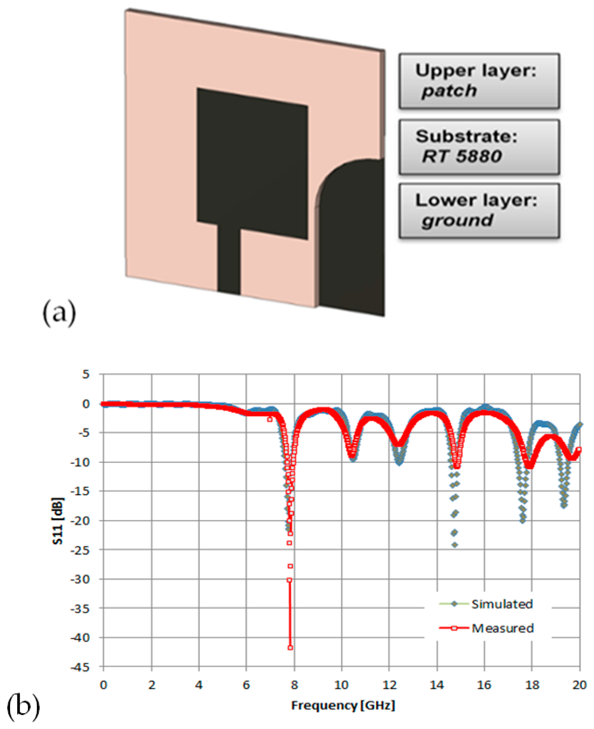
Figure 2.
(a) the crossbar fractal based elementary unit cell of the antenna (dimensions are in mm); (b–d) geometry of the three configurations (mentioned in the text) of microstrip antennas with crossbar fractals.
Figure 2.
(a) the crossbar fractal based elementary unit cell of the antenna (dimensions are in mm); (b–d) geometry of the three configurations (mentioned in the text) of microstrip antennas with crossbar fractals.

Figure 3.
Simulated values of S11 for the antennas with crossbar fractals, for the three configurations.
Figure 3.
Simulated values of S11 for the antennas with crossbar fractals, for the three configurations.

Figure 4.
(a) The Minkowski island fractal based elementary unit cell of the antenna (dimensions are in mm); (b) geometry of the antenna with Minkowski fractal on the lower layer.
Figure 4.
(a) The Minkowski island fractal based elementary unit cell of the antenna (dimensions are in mm); (b) geometry of the antenna with Minkowski fractal on the lower layer.

Figure 5.
Simulated values of S11 for the antenna with ground based on Minkowski fractal.

Figure 6.
Picture of the fabricated antenna. Picture of the fabricated antenna. (a) One side of the antenna (b) another side of the antenna.
Figure 6.
Picture of the fabricated antenna. Picture of the fabricated antenna. (a) One side of the antenna (b) another side of the antenna.
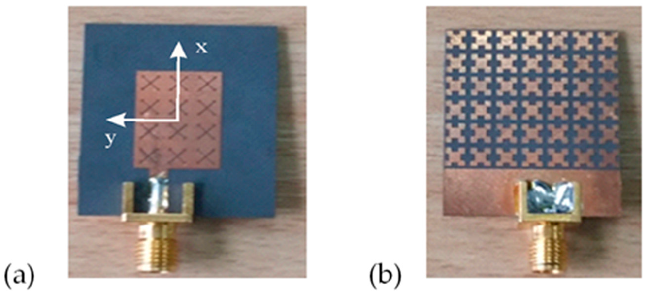
Figure 7.
Results of simulated and measured values of S11 for the double-fractal antenna.
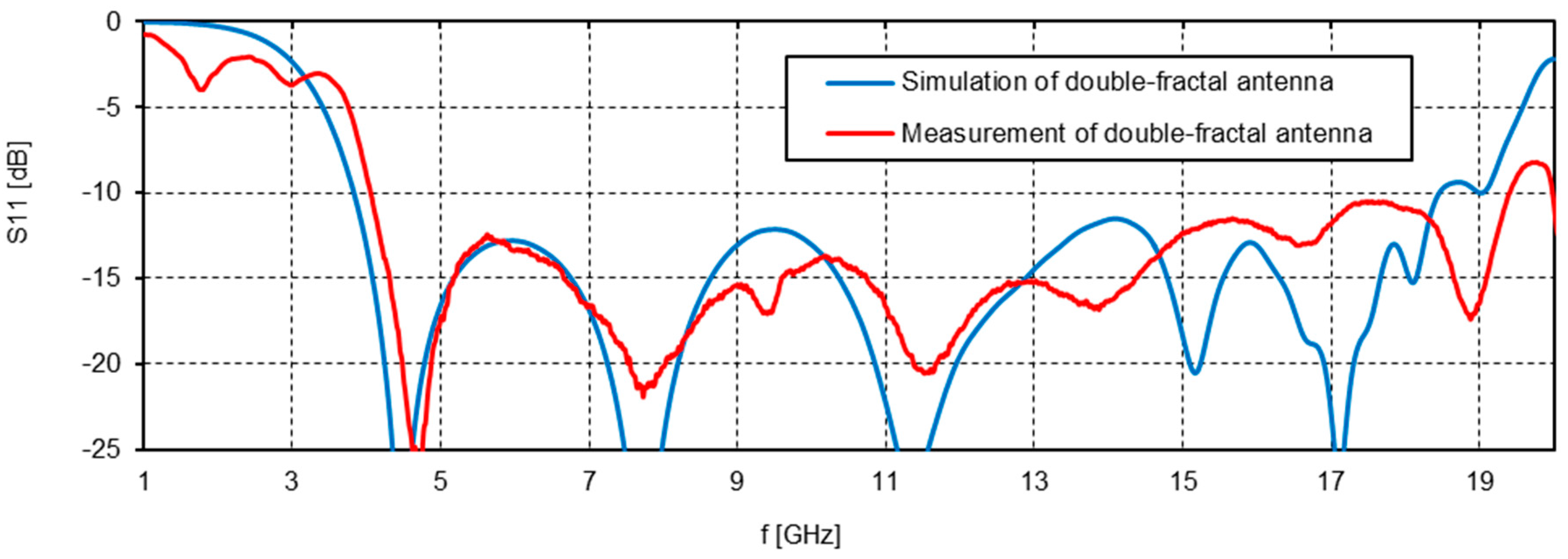
Figure 8.
Results of measured radiation patterns of the antenna.
© 2018 by the authors. Licensee MDPI, Basel, Switzerland. This article is an open access article distributed under the terms and conditions of the Creative Commons Attribution (CC BY) license (http://creativecommons.org/licenses/by/4.0/).
Share and Cite
MDPI and ACS Style
Kubacki, R.; Czyżewski, M.; Laskowski, D. Minkowski Island and Crossbar Fractal Microstrip Antennas for Broadband Applications. Appl. Sci. 2018, 8, 334. https://doi.org/10.3390/app8030334
AMA Style
Kubacki R, Czyżewski M, Laskowski D. Minkowski Island and Crossbar Fractal Microstrip Antennas for Broadband Applications. Applied Sciences. 2018; 8(3):334. https://doi.org/10.3390/app8030334
Chicago/Turabian StyleKubacki, Roman, Mirosław Czyżewski, and Dariusz Laskowski. 2018. "Minkowski Island and Crossbar Fractal Microstrip Antennas for Broadband Applications" Applied Sciences 8, no. 3: 334. https://doi.org/10.3390/app8030334
Note that from the first issue of 2016, this journal uses article numbers instead of page numbers. See further details here.